EP4353799A1 - Apparatus for treating fluid with ultraviolet light - Google Patents
Apparatus for treating fluid with ultraviolet light Download PDFInfo
- Publication number
- EP4353799A1 EP4353799A1 EP22837511.9A EP22837511A EP4353799A1 EP 4353799 A1 EP4353799 A1 EP 4353799A1 EP 22837511 A EP22837511 A EP 22837511A EP 4353799 A1 EP4353799 A1 EP 4353799A1
- Authority
- EP
- European Patent Office
- Prior art keywords
- flow channel
- ultraviolet light
- fluid
- treatment device
- light source
- Prior art date
- Legal status (The legal status is an assumption and is not a legal conclusion. Google has not performed a legal analysis and makes no representation as to the accuracy of the status listed.)
- Pending
Links
Images










Classifications
-
- A—HUMAN NECESSITIES
- A61—MEDICAL OR VETERINARY SCIENCE; HYGIENE
- A61L—METHODS OR APPARATUS FOR STERILISING MATERIALS OR OBJECTS IN GENERAL; DISINFECTION, STERILISATION OR DEODORISATION OF AIR; CHEMICAL ASPECTS OF BANDAGES, DRESSINGS, ABSORBENT PADS OR SURGICAL ARTICLES; MATERIALS FOR BANDAGES, DRESSINGS, ABSORBENT PADS OR SURGICAL ARTICLES
- A61L2/00—Disinfection or sterilisation of materials or objects, in general; Accessories therefor
- A61L2/02—Disinfection or sterilisation of materials or objects, in general; Accessories therefor using physical processes
- A61L2/08—Radiation
- A61L2/10—Ultraviolet [UV] radiation
-
- A—HUMAN NECESSITIES
- A61—MEDICAL OR VETERINARY SCIENCE; HYGIENE
- A61L—METHODS OR APPARATUS FOR STERILISING MATERIALS OR OBJECTS IN GENERAL; DISINFECTION, STERILISATION OR DEODORISATION OF AIR; CHEMICAL ASPECTS OF BANDAGES, DRESSINGS, ABSORBENT PADS OR SURGICAL ARTICLES; MATERIALS FOR BANDAGES, DRESSINGS, ABSORBENT PADS OR SURGICAL ARTICLES
- A61L2/00—Disinfection or sterilisation of materials or objects, in general; Accessories therefor
- A61L2/26—Accessories
-
- A—HUMAN NECESSITIES
- A61—MEDICAL OR VETERINARY SCIENCE; HYGIENE
- A61L—METHODS OR APPARATUS FOR STERILISING MATERIALS OR OBJECTS IN GENERAL; DISINFECTION, STERILISATION OR DEODORISATION OF AIR; CHEMICAL ASPECTS OF BANDAGES, DRESSINGS, ABSORBENT PADS OR SURGICAL ARTICLES; MATERIALS FOR BANDAGES, DRESSINGS, ABSORBENT PADS OR SURGICAL ARTICLES
- A61L9/00—Disinfection, sterilisation or deodorisation of air
- A61L9/16—Disinfection, sterilisation or deodorisation of air using physical phenomena
- A61L9/18—Radiation
- A61L9/20—Ultraviolet radiation
-
- B—PERFORMING OPERATIONS; TRANSPORTING
- B01—PHYSICAL OR CHEMICAL PROCESSES OR APPARATUS IN GENERAL
- B01J—CHEMICAL OR PHYSICAL PROCESSES, e.g. CATALYSIS OR COLLOID CHEMISTRY; THEIR RELEVANT APPARATUS
- B01J19/00—Chemical, physical or physico-chemical processes in general; Their relevant apparatus
- B01J19/08—Processes employing the direct application of electric or wave energy, or particle radiation; Apparatus therefor
- B01J19/12—Processes employing the direct application of electric or wave energy, or particle radiation; Apparatus therefor employing electromagnetic waves
-
- C—CHEMISTRY; METALLURGY
- C02—TREATMENT OF WATER, WASTE WATER, SEWAGE, OR SLUDGE
- C02F—TREATMENT OF WATER, WASTE WATER, SEWAGE, OR SLUDGE
- C02F1/00—Treatment of water, waste water, or sewage
- C02F1/30—Treatment of water, waste water, or sewage by irradiation
- C02F1/32—Treatment of water, waste water, or sewage by irradiation with ultraviolet light
- C02F1/325—Irradiation devices or lamp constructions
-
- A—HUMAN NECESSITIES
- A61—MEDICAL OR VETERINARY SCIENCE; HYGIENE
- A61L—METHODS OR APPARATUS FOR STERILISING MATERIALS OR OBJECTS IN GENERAL; DISINFECTION, STERILISATION OR DEODORISATION OF AIR; CHEMICAL ASPECTS OF BANDAGES, DRESSINGS, ABSORBENT PADS OR SURGICAL ARTICLES; MATERIALS FOR BANDAGES, DRESSINGS, ABSORBENT PADS OR SURGICAL ARTICLES
- A61L2202/00—Aspects relating to methods or apparatus for disinfecting or sterilising materials or objects
- A61L2202/10—Apparatus features
- A61L2202/11—Apparatus for generating biocidal substances, e.g. vaporisers, UV lamps
-
- A—HUMAN NECESSITIES
- A61—MEDICAL OR VETERINARY SCIENCE; HYGIENE
- A61L—METHODS OR APPARATUS FOR STERILISING MATERIALS OR OBJECTS IN GENERAL; DISINFECTION, STERILISATION OR DEODORISATION OF AIR; CHEMICAL ASPECTS OF BANDAGES, DRESSINGS, ABSORBENT PADS OR SURGICAL ARTICLES; MATERIALS FOR BANDAGES, DRESSINGS, ABSORBENT PADS OR SURGICAL ARTICLES
- A61L2209/00—Aspects relating to disinfection, sterilisation or deodorisation of air
- A61L2209/10—Apparatus features
- A61L2209/12—Lighting means
-
- C—CHEMISTRY; METALLURGY
- C02—TREATMENT OF WATER, WASTE WATER, SEWAGE, OR SLUDGE
- C02F—TREATMENT OF WATER, WASTE WATER, SEWAGE, OR SLUDGE
- C02F2201/00—Apparatus for treatment of water, waste water or sewage
- C02F2201/32—Details relating to UV-irradiation devices
- C02F2201/322—Lamp arrangement
- C02F2201/3222—Units using UV-light emitting diodes [LED]
-
- C—CHEMISTRY; METALLURGY
- C02—TREATMENT OF WATER, WASTE WATER, SEWAGE, OR SLUDGE
- C02F—TREATMENT OF WATER, WASTE WATER, SEWAGE, OR SLUDGE
- C02F2201/00—Apparatus for treatment of water, waste water or sewage
- C02F2201/32—Details relating to UV-irradiation devices
- C02F2201/322—Lamp arrangement
- C02F2201/3226—Units using UV-light emitting lasers
-
- C—CHEMISTRY; METALLURGY
- C02—TREATMENT OF WATER, WASTE WATER, SEWAGE, OR SLUDGE
- C02F—TREATMENT OF WATER, WASTE WATER, SEWAGE, OR SLUDGE
- C02F2201/00—Apparatus for treatment of water, waste water or sewage
- C02F2201/32—Details relating to UV-irradiation devices
- C02F2201/322—Lamp arrangement
- C02F2201/3227—Units with two or more lamps
-
- C—CHEMISTRY; METALLURGY
- C02—TREATMENT OF WATER, WASTE WATER, SEWAGE, OR SLUDGE
- C02F—TREATMENT OF WATER, WASTE WATER, SEWAGE, OR SLUDGE
- C02F2201/00—Apparatus for treatment of water, waste water or sewage
- C02F2201/32—Details relating to UV-irradiation devices
- C02F2201/322—Lamp arrangement
- C02F2201/3228—Units having reflectors, e.g. coatings, baffles, plates, mirrors
-
- C—CHEMISTRY; METALLURGY
- C02—TREATMENT OF WATER, WASTE WATER, SEWAGE, OR SLUDGE
- C02F—TREATMENT OF WATER, WASTE WATER, SEWAGE, OR SLUDGE
- C02F2201/00—Apparatus for treatment of water, waste water or sewage
- C02F2201/32—Details relating to UV-irradiation devices
- C02F2201/328—Having flow diverters (baffles)
-
- C—CHEMISTRY; METALLURGY
- C02—TREATMENT OF WATER, WASTE WATER, SEWAGE, OR SLUDGE
- C02F—TREATMENT OF WATER, WASTE WATER, SEWAGE, OR SLUDGE
- C02F2301/00—General aspects of water treatment
- C02F2301/02—Fluid flow conditions
- C02F2301/028—Tortuous
-
- C—CHEMISTRY; METALLURGY
- C02—TREATMENT OF WATER, WASTE WATER, SEWAGE, OR SLUDGE
- C02F—TREATMENT OF WATER, WASTE WATER, SEWAGE, OR SLUDGE
- C02F2303/00—Specific treatment goals
- C02F2303/04—Disinfection
Definitions
- the present invention relates to an ultraviolet light fluid treatment device.
- Patent Document 1 discloses a device that emits ultraviolet light from a light emitting element into a flow channel in which fluid flows.
- Patent Document 1 Japanese Laid-open Patent Publication No. 2018-140001
- an ultraviolet light fluid treatment device includes an inlet and an outlet of fluid; a flow channel connecting the inlet and the outlet and including a plurality of branch flow channels branching from the inlet, and a merged flow channel connected to a downstream side of each of the branch flow channels; a first light source configured to emit ultraviolet light to the merged flow channel; and a plurality of second light sources configured to emit the ultraviolet light to the plurality of respective branch flow channels.
- an ultraviolet light fluid treatment device that can enhance a treatment effect can be provided.
- FIG. 1 is a perspective view of an ultraviolet light fluid treatment device 1 according to a first embodiment of the present invention.
- FIG. 2 is a cross-sectional view of the ultraviolet light fluid treatment device 1 taken through line II-II of FIG. 1 .
- three axes orthogonal to each other are defined as an X-axis, a Y-axis, and a Z-axis.
- the cross section illustrated in FIG. 2 is parallel to the X-axis and the Z-axis, and is orthogonal to the Y-axis.
- the ultraviolet light fluid treatment device 1 includes a first end portion 10, a second end portion 20, and an intermediate portion 50 located between the first end portion 10 and the second end portion 20. Further, the ultraviolet light fluid treatment device 1 includes a first light source 71 and a second light source 72. In the example illustrated in FIG. 1 and FIG. 2 , the first light source 71 is disposed in the first end portion 10 and the second light source 72 is disposed in the second end portion 20.
- the material of the first end portion 10, the second end portion 20, and the intermediate portion 50 is metal, and is, for example, stainless steel.
- the first end portion 10, the second end portion 20, and the intermediate portion 50 may be separated from one another, or may be integrated into one another.
- the flows of fluid are indicated by bold arrows.
- the fluid such as liquid or gas flows into the first end portion 10 from the outside of the ultraviolet light fluid treatment device 1.
- the fluid further flows from the first end portion 10 through the intermediate portion 50 to the second end portion 20, and flows out from the second end portion 20 to the outside of the ultraviolet light fluid treatment device 1.
- the first end portion 10 includes an inlet 11 of the fluid, an upstream flow channel 12, a first light source placement portion 13, and a first window 14.
- the inlet 11 includes a hole leading from the outside of the ultraviolet light fluid treatment device 1 to the inside of the first end portion 10.
- An external pipe is connected to the inlet 11, and the fluid flows into the inlet 11 from the external pipe.
- the cross-sectional shape of the inlet 11 orthogonal to a direction in which the fluid flows is, for example, a circular shape.
- the inlet 11 includes an inlet port 11a formed as a circular opening, for example.
- a central axis C1 passing through the center of the circular cross-sectional shape of the inlet 11 is parallel to the X-axis direction.
- the upstream flow channel 12 is connected to the inlet 11 within the first end portion 10.
- the upstream flow channel 12 branches into a plurality of flow channels from the inlet 11.
- the upstream flow channel 12 branches into two flow channels from the inlet 11.
- the upstream flow channel 12 branches from the inlet 11 in directions opposite to each other in the Z-axis direction that is orthogonal to the central axis C1.
- the first light source placement portion 13 is formed as a space within the first end portion 10 in which the first light source 71 can be disposed. As illustrated in FIG. 1 , a first opening 13a leading to the first light source placement portion 13 is formed in a lateral surface 10a of the first end portion 10. The first light source 71 can be detachably attached to the first light source placement portion 13 through the first opening 13a.
- the first light source placement portion 13 is formed as a space separated from each flow channel of the ultraviolet light fluid treatment device 1, and the first light source 71 is not exposed to the fluid and is protected from the fluid. For example, if the fluid is liquid, the first light source 71 does not require a waterproof structure.
- the first light source 71 can be detached, replaced, and maintained while the fluid is flowing in the ultraviolet light fluid treatment device 1.
- the first light source placement portion 13 may be provided within the intermediate portion 50.
- the first opening 13a leading to the first light source placement portion 13 is formed in a third wall 53 or a fourth wall 54 of the intermediate portion 50 described later.
- the first light source 71 emits ultraviolet light.
- the peak wavelength of the ultraviolet light emitted from the first light source 71 is, for example, 10 nm or more and 400 nm or less.
- the first light source 71 includes light emitting elements.
- As the light emitting elements light emitting diodes (LEDs) or laser diodes (LDs) can be used, for example.
- As the first light source 71 a light emitting device in which light emitting elements are mounted on a wiring substrate, a light emitting device in which housings including light emitting elements are mounted on a wiring substrate, or the like can be used.
- the first light source 71 has a first surface 71a and a second surface 71b located opposite to the first surface 71a.
- the first surface 71a is a light emitting surface, and the ultraviolet light is emitted from the first surface 71a.
- the first window 14 is disposed to face the first surface 71a of the first light source 71.
- the first surface 71a is located between the first window 14 and the second surface 71b of the first light source 71 in the X-axis direction, and a portion of the upstream flow channel 12 is located between the second surface 71b and the inlet 11 in the X-axis direction.
- the first window 14 is formed of a material having transmissivity with respect to the wavelength of the light emitted from the first light source 71.
- Examples of the material of the first window 14 include inorganic materials formed of at least one material selected from the group consisting of quartz glass, borosilicate glass, calcium fluoride glass, aluminoborosilicate glass, oxynitride glass, chalcogenide glass, and sapphire.
- the second end portion 20 includes an outlet 15 of the fluid, a second light source placement portion 16, and a second window 17.
- the outlet 15 includes a hole leading from the inside of the second end portion 20 to the outside of the ultraviolet light fluid treatment device 1.
- An external pipe is connected to the outlet 15.
- the fluid flowing in the ultraviolet light fluid treatment device 1 flows out from the outlet 15 into the external pipe.
- the cross-sectional shape of the outlet 15 orthogonal to the direction in which the fluid flows is, for example, a circular shape.
- the outlet 15 includes an outlet port 15a formed as a circular opening, for example.
- a central axis C2 passing through the center of the circular cross-sectional shape of the outlet 15 preferably coincides with the central axis C1 of the inlet 11. Accordingly, the ultraviolet light fluid treatment device 1 can be easily connected to an intermediate portion of a straight pipe that is generally available.
- the second light source placement portion 16 is formed as a space within the second end portion 20 in which the second light source 72 can be disposed.
- a plurality of second light sources 72 is disposed within the second end portion 20.
- two second light sources 72 are disposed within the second end portion 20.
- two second light source placement portions 16 are formed within the second end portion 20.
- the outlet 15 is interposed between the two second light source placement portions 16 in the Z-axis direction.
- a second opening 16a leading to a corresponding second light source placement portion 16 is formed in a lateral surface 20a of the second end portion 20.
- a second light source 72 can be detachably attached to the corresponding second light source placement portion 16 through the second opening 16a.
- the second light source placement portion 16 is formed as a space separated from each flow channel of the ultraviolet light fluid treatment device 1, and the second light source 72 is not exposed to the fluid and is protected from the fluid. For example, if the fluid is liquid, the second light source 72 does not require a waterproof structure. Further, the second light source 72 can be detached, replaced, and maintained while the fluid is flowing in the ultraviolet light fluid treatment device 1.
- the second light source placement portion 16 may be disposed within the intermediate portion 50. In this case, the second opening 16a leading to the second light source placement portion 16 is formed in the third wall 53 or the fourth wall 54 of the intermediate portion 50 described later.
- the second light source 72 emits ultraviolet light.
- the same light source as the first light source 71 can be used.
- a light source having an emission peak wavelength different from that of the first light source 71 may be used.
- the second light source 72 has a first surface 72a and a second surface 72b located opposite to the first surface 72a.
- the first surface 72a is a light emitting surface, and the ultraviolet light is emitted from the first surface 72a.
- the second window 17 is disposed to face the first surface 72a of the second light source 72.
- the second window 17 is formed of a material having transmissivity with respect to the wavelength of the light emitted from the second light source 72.
- the second window 17 is formed of, for example, glass.
- the first surface 72a is located between the second window 17 and the second surface 72b of the second light source 72 in the X-axis direction.
- the second light source 72 includes, for example, a wiring substrate 72d, a plurality of light emitting elements 72e mounted on the wiring substrate 72d, and a housing 72f covering the wiring substrate 72d and the light emitting elements 72e.
- An insertion port 72c of a connector to be electrically connected to the wiring substrate 72d is formed in the housing 72f.
- the first light source 71 can be configured in the same manner as the second light source 72.
- the first light source 71 and the second light source 72 may both have a waterproof structure.
- the first light source placement portion 13 and the second light source placement portion 16 may be provided within a flow channel 100 of the ultraviolet light fluid treatment device 1.
- first window 14 and the second window 17 may be omitted.
- ultraviolet light from the first light source 71 and the second light source 72 may be directly emitted from the first light source placement portion 13 and the second light source placement portion 16 into the flow channel 100.
- the second end portion 20 further includes a downstream flow channel 110.
- the downstream flow channel 110 branches from the outlet 15 in the Z-axis direction, and leads to spaces each facing the second light source placement portion 16. A portion of the fluid, flowing into the outlet 15, can flow into the downstream flow channel 110 and cool the second light source 72 from the second surface 72b side. Accordingly, a decrease in light emission efficiency due to heat generation accompanying light emission of the second light source 72 can be reduced.
- the fluid flowing in the upstream flow channel 12 of the first end portion 10 can cool the first light source 71 from the second surface 71b side. Accordingly, a decrease in light emission efficiency due to heat generation accompanying light emission of the first light source 71 can be reduced.
- the intermediate portion 50 has four walls (a first wall 51, a second wall 52, the third wall 53, and the fourth wall 54) constituting a housing of the intermediate portion 50.
- the first wall 51 and the second wall 52 are separated from each other in the Z-axis direction.
- the third wall 53 and the fourth wall 54 are separated from each other in the Y-axis direction.
- the intermediate portion 50 includes a plurality of partition members 61 to 64 disposed in a space surrounded by the first wall 51, the second wall 52, the third wall 53, and the fourth wall 54.
- partition members a first partition member 61, a second partition member 62, a third partition member 63, and a fourth partition member 64 are disposed in the intermediate portion 50.
- Each of the first partition member 61, the second partition member 62, the third partition member 63, and the fourth partition member 64 is a plate member having a rectangular shape and extending in the X-axis direction.
- the first wall 51, the first partition member 61, the second partition member 62, the third partition member 63, the fourth partition member 64, and the second wall 52 are separated from one another in the Z-axis direction.
- Each of first flow channels 81a and 81b, second flow channels 82a and 82b, and a merged flow channel 90 may be configured with a tubular member.
- the first partition member 61 is positioned between the first wall 51 and the second partition member 62
- the second partition member 62 is positioned between the first partition member 61 and the third partition member 63
- the third partition member 63 is positioned between the second partition member 62 and the fourth partition member 64
- the fourth partition member 64 is positioned between the third partition member 63 and the second wall 52.
- the first partition member 61, the second partition member 62, the third partition member 63, and the fourth partition member 64 are interposed between the third wall 53 and the fourth wall 54 in the Y-axis direction. Both end portions in the Y-axis direction of each of the first partition member 61, the second partition member 62, the third partition member 63, and the fourth partition member 64 are supported by the third wall 53 and the fourth wall 54.
- the first partition member 61 extends from a connection portion between the first partition member 61 and the first end portion 10 toward the second end portion 20. The other end of the first partition member 61 is separated from the second end portion 20.
- the second partition member 62 extends from a connection portion between the second partition member 62 and the second end portion 20 toward the first end portion 10. The other end of the second partition member 62 is separated from the first end portion 10.
- the third partition member 63 is connected to the second end portion 20.
- the third partition member 63 extends from a connection portion between the third partition member 63 and the second end portion 20 toward the first end portion 10. The other end of the third partition member 63 is separated from the first end portion 10.
- the fourth partition member 64 is connected to the first end portion 10.
- the fourth partition member 64 extends from a connection portion between the fourth partition member 64 and the first end portion 10 toward the second end portion 20.
- the other end of the fourth partition member 64 is separated from the second end portion 20.
- the intermediate portion 50 includes the flow channel 100 that connects the inlet 11 and the outlet 15 and is defined by the walls 51 to 54 and the partition members 61 to 64 described above.
- the flow channel 100 includes a plurality of branch flow channels 80a and 80b branching from the inlet 11, and the merged flow channel 90 connected to the downstream side of each of the branch flow channels 80a and 80b.
- the merged flow channel 90 is interposed between the two branch flow channels 80a and 80b in the Z-axis direction.
- At least one of the branch flow channels 80a and 80b include a first flow channel and a second flow channel.
- the branch flow channel 80a includes the first flow channel 81a and the second flow channel 82a
- the branch flow channel 80b includes the first flow channel 81b and the second flow channel 82b.
- the branch flow channel 80a includes the first flow channel 81a and the second flow channel 82a.
- the first flow channel 81a is disposed upstream of the second flow channel 82a, and the second flow channel 82a is disposed downstream of the first flow channel 81a.
- upstream refers to a side relatively close to the inlet 11 and the term “downstream” refers to a side relatively close to the outlet 15 in the flow channel from the inlet 11 toward the outlet 15.
- the branch flow channel 80b includes the first flow channel 81b and the second flow channel 82b.
- the first flow channel 81b is disposed upstream of the second flow channel 82b, and the second flow channel 82b is disposed downstream of the first flow channel 81b.
- the first flow channel 81a of the branch flow channel 80a is defined by the first wall 51, the first partition member 61, the third wall 53, and the fourth wall 54.
- the second flow channel 82a of the branch flow channel 80a is defined by the first partition member 61, the second partition member 62, the third wall 53, and the fourth wall 54.
- the first flow channel 81b of the branch flow channel 80b is defined by the second wall 52, the fourth partition member 64, the third wall 53, and the fourth wall 54.
- the second flow channel 82b of the branch flow channel 80b is defined by the third partition member 63, the fourth partition member 64, the third wall 53, and the fourth wall 54.
- each of the first flow channels 81a and 81b is connected to the upstream flow channel 12 formed within the first end portion 10.
- the first flow channels 81a and 81b extend in a first direction d1 from respective connection portions connected to the upstream flow channel 12.
- the first direction d1 is, for example, a direction parallel to the X-axis direction.
- the fluid flows in each of the first flow channels 81a and 81b in the first direction d1.
- the first direction d1 may be a direction that is inclined with respect to the X-axis direction.
- the first flow channel 81a of the branch flow channel 80a is connected to the second flow channel 82a through a space between the first partition member 61 and the second end portion 20.
- the first flow channel 81b of the branch flow channel 80b communicates with the second flow channel 82b through a space between the fourth partition member 64 and the second end portion 20.
- the second flow channels 82a and 82b extend in a direction different from the first direction d1 from respective portions communicating with the first flow channels 81a and 81b.
- the fluid flows in each of the second flow channels 82a and 82b in a second direction d2.
- the second direction d2 is a direction opposite to the first direction d1.
- the first flow channels 81a and 81b, the second flow channels 82a and 82b, and the merged flow channel 90 are adjacent to one another in the Z-axis direction.
- the first flow channel 81a of the branch flow channel 80a is adjacent to the second flow channel 82a of the branch flow channel 80a with the first partition member 61 interposed therebetween.
- the first flow channel 81b of the branch flow channel 80b is adjacent to the second flow channel 82b of the branch flow channel 80b with the fourth partition member 64 interposed therebetween.
- the merged flow channel 90 is adjacent to the second flow channel 82a of the branch flow channel 80a with the second partition member 62 interposed therebetween, and is adjacent to the second flow channel 82b of the branch flow channel 80b with the third partition member 63 interposed therebetween.
- the two second flow channels 82a and 82b are positioned between the two first flow channels 81a and 81b, and the merged flow channel 90 is positioned between the two second flow channels 82a and 82b.
- the second flow channel 82a of the branch flow channel 80a is connected to the merged flow channel 90 through a space between the second partition member 62 and the first end portion 10.
- the second flow channel 82b of the branch flow channel 80b is connected to the merged flow channel 90 through a space between the third partition member 63 and the first end portion 10.
- the merged flow channel 90 extends in the X-axis direction from a portion communicating with the two second flow channels 82a and 82b, and is connected to the outlet 15.
- the fluid flowing in the second flow channels 82a and 82b merges into the merged flow channel 90 and flows in the merged flow channel 90 in the first direction d1.
- the first light source 71 is disposed at a position where the merged flow channel 90 can be irradiated with the ultraviolet light.
- the first light source 71 is disposed in the first light source placement portion 13 provided in the first end portion 10.
- the first surface (light emitting surface) 71a of the first light source 71 faces, through the first window 14, a merging portion of the two second flow channels 82a and 82b into the merged flow channel 90.
- the ultraviolet light emitted from the first surface 71a of the first light source 71 travels from the merging portion of the second flow channels 82a and 82b into the merged flow channel 90.
- One or more second light sources 72 are disposed at a position where one branch flow channel can be irradiated with the ultraviolet light.
- two second light sources 72 are disposed at respective positions where the branch flow channels 80a and 80b can be irradiated with the ultraviolet light.
- the two second light sources 72 are disposed in respective second light source placement portions 16 provided in the second end portion 20.
- the two second light sources 72 are disposed at positions where the first flow channels 81a and 81b and the second flow channels 82a and 82b can be irradiated with the ultraviolet light.
- one second light source 72 of the two second light sources 72 is disposed at a position facing, through a corresponding second window 17, a portion where the first flow channel 81a communicates with the second flow channel 82a in the branch flow channel 80a.
- the other second light source 72 is disposed at a position facing, through a corresponding second window 17, a portion where the first flow channel 81b communicates with the second flow channel 82b in the branch flow channel 80b.
- the ultraviolet light emitted from a first surface 72a of the one second light source 72 travels from the communication portion between the first flow channel 81a and the second flow channel 82a into the first flow channel 81a and the second flow channel 82a.
- the ultraviolet light emitted from a first surface 72a of the other second light source 72 travels from the communication portion between the first flow channel 81b and the second flow channel 82b into the first flow channel 81b and the second flow channel 82b.
- the ultraviolet light fluid treatment device 1 treats fluid such as liquid or gas by irradiating the fluid with ultraviolet light.
- the ultraviolet light fluid treatment device 1 can treat water by irradiating the water with ultraviolet light so as to reduce bacteria and viruses in the water after the treatment as compared to before the treatment.
- the inlet 11 is connected to the external upstream pipe directly or via a joint member.
- the outlet 15 is connected to the external downstream pipe directly or via a joint member.
- the fluid flowing through the external upstream pipe flows into the inlet 11, and is separated into two at the upstream flow channel 12.
- One portion of the fluid separated into two flows into the first flow channel 81a of the branch flow channel 80a, and the other portion of the fluid flows into the first flow channel 81b of the branch flow channel 80b.
- the fluid flowing into the first flow channels 81a and 81b flows in each of the first flow channels 81a and 81b in the first direction d1, and then flows into the second flow channels 82a and 82b at the ends, near the second end portion 20, of the first flow channels 81a and 81b.
- the fluid flowing into the second flow channels 82a and 82b flows in each of the second flow channels 82a and 82b in the second direction d2.
- the fluid flowing in the first flow channels 81a and 81b and the second flow channels 82a and 82b is irradiated with the ultraviolet light from the second light sources 72.
- the fluid flowing in the second flow channels 82a and 82b in the second direction d2 flows into the merged flow channel 90.
- the fluid flowing into the merged flow channel 90 flows in the merged flow channel 90 in the first direction d1.
- the fluid flowing in the merged flow channel 90 is irradiated with the ultraviolet light from the first light source 71.
- the fluid flowing in the merged flow channel 90 flows out from the outlet 15 to the external pipe connected to the outlet 15.
- the fluid flowing into the inside of the ultraviolet light fluid treatment device 1 from the inlet 11 is separated one or more times, merges again, and flows out from the outlet 15. Accordingly, the length of the flow channel in which the fluid flows from the external upstream pipe connected to the inlet 11 to the external downstream pipe connected to the outlet 15 can be increased, as compared to when the fluid flows from the inlet 11 to the outlet 15 without being separated.
- the fluid flowing in the branch flow channels 80a and 80b is irradiated with the ultraviolet light from the second light sources 72, and the fluid flowing from the branch flow channels 80a and 80b into the merged flow channel 90 and flows in the merged flow channel 90 is irradiated with the ultraviolet light from the first light source 71. Accordingly, the integrated luminance of the ultraviolet light emitted to the fluid flowing in the ultraviolet light fluid treatment device 1 can be increased, and an effect of treating the fluid with the ultraviolet light can be enhanced.
- the first direction d1 in which the fluid flows in the first flow channels 81a and 81b is different from the second direction d2 in which the fluid flows in the second flow channels 82a and 82b.
- the lengths of the branch flow channels 80a and 80b can be increased while suppressing an increase in the dimension of the flow channel 100 between the inlet 11 and the outlet 15 (the dimension of the flow channel 100 in the X-axis direction).
- the first direction d1 and the second direction d2 are opposite to each other, and thus the lengths of the branch flow channels 80a and 80b can be increased while suppressing an increase in the dimensions of the flow channel 100 in the X-axis direction and the Z-axis direction.
- the flow channels of the flow channel 100 preferably overlap one another only in one direction (in the present embodiment, in the Z-axis direction) in a cross-sectional view.
- the size of the ultraviolet light fluid treatment device 1 can be easily reduced as compared to a configuration in which flow channels of a flow channel are arranged concentrically one above another.
- annular members defining the flow channels are separated, and thus parts management efficiency and assembly efficiency would be decreased.
- both end portions of each of the partition members 61 to 64 in the Y-axis direction are supported by the third wall 53 and the fourth wall 54 constituting part of the housing of the intermediate portion 50, and thus the partition members 61 to 64 can be integrated.
- the branch flow channel 80a does not necessarily include the two flow channels (the first flow channel 81a and the second flow channel 82a), and the branch flow channel 80b does not necessarily include the two flow channels (the first flow channel 81b and the second flow channel 82b).
- Each of the branch flow channels 80a and 80b may include one flow channel or three or more flow channels. As the number of flow channels included in each of the branch flow channels 80a and 80b increases, the lengths of the branch flow channels 80a and 80b increase. Thus, the integrated luminance of the ultraviolet light emitted to the fluid flowing in the branch flow channels 80a and 80b can be increased. As the number of flow channels included in each of the branch flow channels 80a and 80b decreases, pressure loss of the fluid flowing in the ultraviolet light fluid treatment device 1 can be reduced.
- each of the branch flow channels 80a and 80b includes a plurality of flow channels
- the fluid flowing in the branch flow channels 80a and 80b can be treated by irradiating at least one of the plurality of flow channels included in each of the branch flow channels 80a and 80b with the ultraviolet light from each of the second light sources 72.
- the second light sources 72 By causing the second light sources 72 to emit the ultraviolet light to two or more or all of the plurality of flow channels included in each of the branch flow channels 80a and 80b, the effect of treating the fluid, flowing in the branch flow channels 80a and 80b, with the ultraviolet light can be further enhanced.
- a flow velocity difference or a flow rate difference between the fluid flowing from the branch flow channel 80a into the merged flow channel 90 and the fluid flowing from the branch flow channel 80b into the merged flow channel 90 is preferably reduced.
- the cross-sectional shape of each of the first flow channels 81a and 81b in a direction orthogonal to the first direction d1 in which the fluid flows is a rectangular shape.
- the cross-sectional shape of each of the second flow channels 82a and 82b in a direction orthogonal to the second direction d2 in which the fluid flows is a rectangular shape.
- the cross-sectional shape of the merged flow channel 90 in a direction orthogonal to the first direction d1 in which the fluid flows is a rectangular shape.
- the cross-sectional area of the first flow channel 81a in the direction orthogonal to the first direction d1 in which the fluid flows, the cross-sectional area of the first flow channel 81b in the direction orthogonal to the first direction d1 in which the fluid flows, the cross-sectional area of the second flow channel 82a in the direction orthogonal to the second direction d2 in which the fluid flows, and the cross-sectional area of the second flow channel 82b in the direction orthogonal to the second direction d2 in which the fluid flows are the same. Therefore, the cross-sectional area of the branch flow channel 80a in the direction orthogonal to the directions in which the fluid flows is the same as the cross-sectional area of the branch flow channel 80b in the direction orthogonal to the directions in which the fluid flows.
- the length from an upstream end 80a1 to a downstream end 80a2 of the branch flow channel 80a is the same as the length from an upstream end 80b1 to a downstream end 80b2 of the branch flow channel 80b.
- a flow velocity difference or a flow rate difference between the fluid flowing from the branch flow channel 80a into the merged flow channel 90 and the fluid flowing from the branch flow channel 80b into the merged flow channel 90 can be reduced. Accordingly, pressure loss of the fluid due to a vortex or turbulence generated in the flow channel 100 can be reduced.
- the cross-sectional area of the first flow channel 81a of the branch flow channel 80a orthogonal to the direction in which the fluid flows is greater than or equal to the cross-sectional area of the inlet 11 orthogonal to the direction in which the fluid flows.
- the cross-sectional area of the first flow channel 81a orthogonal to the direction in which the fluid flows is the same as the cross-sectional area of the inlet 11 orthogonal to the direction in which the fluid flows.
- the cross-sectional area of the first flow channel 81b of the branch flow channel 80b orthogonal to the direction in which the fluid flows is greater than or equal to the cross-sectional area of the inlet 11 orthogonal to the direction in which the fluid flows.
- the cross-sectional area of the first flow channel 81b orthogonal to the direction in which the fluid flows is the same as the cross-sectional area of the inlet 11 orthogonal to the direction in which the fluid flows. Accordingly, the flow velocity of the fluid separated from the inlet 11 and flowing into the first flow channels 81a and 81b can be set to one-half or less of the flow velocity of the fluid flowing in the inlet 11.
- the integrated illuminance of the ultraviolet light emitted from the second light sources 72 to the fluid flowing in the first flow channels 81a and 81b can be increased, and the effect of treating the fluid, flowing in the first flow channels 81a and 81b, with the ultraviolet light can be enhanced.
- the cross-sectional area of the second flow channel 82a of the branch flow channel 80a orthogonal to the direction in which the fluid flows is greater than or equal to the cross-sectional area of the inlet 11 orthogonal to the direction in which the fluid flows.
- the cross-sectional area of the second flow channel 82a orthogonal to the direction in which the fluid flows is the same as the cross-sectional area of the inlet 11 orthogonal to the direction in which the fluid flows.
- the cross-sectional area of the second flow channel 82b of the branch flow channel 80b orthogonal to the direction in which the fluid flows is greater than or equal to the cross-sectional area of the inlet 11 orthogonal to the direction in which the fluid flows.
- the cross-sectional area of the second flow channel 82b orthogonal to the direction in which the fluid flows is the same as the cross-sectional area of the inlet 11 orthogonal to the direction in which the fluid flows. Accordingly, the flow velocity of the fluid separated from the inlet 11, flowing into the first flow channels 81a and 81b, and then flowing in the second flow channels 82a and 82b can be set to one-half or less of the flow velocity of the fluid flowing in the inlet 11.
- the integrated illuminance of the ultraviolet light emitted from the second light sources 72 to the fluid flowing in the second flow channels 82a and 82b can be increased, and the effect of treating the fluid, flowing in the second flow channels 82a and 82b, with the ultraviolet light can be enhanced.
- the cross-sectional area of the merged flow channel 90 in the direction orthogonal to the direction in which the fluid flows is preferably set to be greater than the cross-sectional areas of the second flow channels 82a and 82b in the direction orthogonal to the direction in which the fluid flows. Accordingly, the integrated illuminance of the ultraviolet light emitted from the first light source 71 to the fluid flowing in the merged flow channel 90 can be increased, and effects of treating the fluid, flowing in the merged flow channel 90, with the ultraviolet light can be enhanced.
- the cross-sectional area of the merged flow channel 90 orthogonal to the direction in which the fluid flows is equal to a sum of the cross-sectional area of the second flow channel 82a orthogonal to the direction in which the fluid flows and the cross-sectional area of the second flow channel 82b orthogonal to the direction in which the fluid flows. Therefore, the flow velocity of the fluid flowing in each of the second flow channels 82a and 82b can be approximately the same as the flow velocity of the fluid flowing in the merged flow channel 90.
- pressure loss of the fluid due to a vortex or turbulence can be reduced.
- the merged flow channel 90 is not necessarily disposed between the branch flow channels 80a and 80b.
- the two branch flow channels 80a and 80b illustrated in FIG. 2 may be disposed on the first wall 51 side (in FIG. 2 , on the upper side) of the merged flow channel 90 in the Z-axis direction, or may be disposed on the second wall 52 side (in FIG. 2 , on the lower side) of the merged flow channel 90 in the Z-axis direction.
- the two branch flow channels 80a and 80b disposed on the first wall 51 side or the second wall 52 side of the merged flow channel 90 may be adjacent to each other in the Y-axis direction.
- FIG. 3 is a cross-sectional view of an ultraviolet light fluid treatment device 2 according to a second embodiment of the present invention.
- the ultraviolet light fluid treatment device 2 includes a first end portion 210, a second end portion 220, and an intermediate portion 250, the first light source 71, and the two second light sources 72.
- the first end portion 210 includes an inlet 211
- the second end portion 220 includes an outlet 215.
- the intermediate portion 250 is located between the first end portion 210 and the second end portion 220 in a direction from the inlet 211 toward the outlet 215.
- the intermediate portion 250 includes an upstream flow channel 212 connected to the inlet 211, two branch flow channels 280a and 280b connected to the upstream flow channel 212, and a merged flow channel 290 connected to the outlet 215 side of each of the branch flow channels 280a and 280b.
- FIG. 3 the flows of fluid are indicated by bold arrows.
- An external upstream pipe is connected to the inlet 211, and the fluid flows into the inlet 211 from the external upstream pipe.
- the upstream flow channel 212 branches into two flow channels from the inlet 211.
- the branch flow channels 280a and 280b are connected to the two respective flow channels branching from the upstream flow channel 212.
- the fluid entering from the inlet 211 flows into the two branch flow channels 280a and 280b through the upstream flow channel 212.
- the outlet 215 side of each of the two branch flow channels 280a and 280b is connected to the merged flow channel 290.
- the fluid flowing in the two branch flow channels 280a and 280b merges and flows into the merged flow channel 290.
- An external downstream pipe is connected to the outlet 215, and the fluid flowing in the merged flow channel 290 flows out from the outlet 215 to the external downstream pipe.
- the first light source 71 is disposed in the intermediate portion 250.
- the first surface (light emitting surface) 71a of the first light source 71 faces, through the first window 14, a portion where the two branch flow channels 280a and 280b are connected to the merged flow channel 290.
- the first light source 71 can emit ultraviolet light into the merged flow channel 290 in a direction from the inlet 211 toward the outlet 215.
- One second light source 72 of the two second light sources 72 is disposed at a position where the branch flow channel 280a of the two branch flow channels 280a and 280b can be irradiated with ultraviolet light.
- the other second light source 72 is disposed at a position where the branch flow channel 280b can be irradiated with ultraviolet light.
- the first surface (light emitting surface) 72a of the one second light source 72 of the two second light sources 72 faces the branch flow channel 280a through the second window 17, and the first surface (light emitting surface) 72a of the other second light source 72 faces the branch flow channel 280b through the second window 17.
- the one second light source 72 can emit the ultraviolet light into the branch flow channel 280a in a direction from the inlet 211 toward the outlet 215.
- the other second light source 72 can emit the ultraviolet light into the branch flow channel 280b in a direction from the inlet 211 toward the outlet 215.
- the fluid flowing into the inside of the ultraviolet light fluid treatment device 2 from the inlet 211 is separated one or more times, merges again, and flows out from the outlet 215. Accordingly, the length of the flow channel in which the fluid flows from the external upstream pipe connected to the inlet 211 to the external downstream pipe connected to the outlet 215 can be increased, as compared to when the fluid flows from the inlet 211 to the outlet 215 without being separated.
- the fluid flowing in the branch flow channels 280a and 280b is irradiated with the ultraviolet light from the second light sources 72, and the fluid flowing from the branch flow channels 280a and 280b into the merged flow channel 290 and flowing in the merged flow channel 290 is irradiated with the ultraviolet light from the first light source 71. Accordingly, the integrated luminance of the ultraviolet light emitted to the fluid flowing in the ultraviolet light fluid treatment device 2 can be increased, and the effect of treating the fluid with the ultraviolet light can be enhanced.
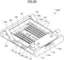
- a light source 170 illustrated in FIG. 4A can be used as each of the first light source and the second light sources described above.
- the light source 170 includes a wiring substrate 171 and a plurality of light emitting elements.
- the light emitting elements are mounted on the surface of the wiring substrate 171.
- the shape of the wiring substrate 171 in a plan view as viewed from the surface side of the wiring substrate 171 is, for example, a rectangle, and the center of the wiring substrate 171 is positioned at the intersection of two diagonal lines of the rectangle.
- the wiring substrate 171 has a first region 181 and a second region 182.
- the first region 181 and the second region 182 are arranged side by side in one direction of the wiring substrate 171.
- the wiring substrate 171 can further have a third region 183.
- the third region 183 is located between the first region 181 and the second region 182 in a plane parallel to the surface of the wiring substrate 171.
- the third region 183 includes the center of the wiring substrate 171. If the third region 183 is not provided, the center of the wiring substrate 171 is located, for example, at the boundary between the first region 181 and the second region 182. The first region 181 or the second region 182 may include the center of the wiring substrate 171.
- the width of the third region 183 in the direction in which the first region 181, the third region 183, and the second region 182 are aligned is preferably the same as or greater than the thickness of the first partition member 61 and the fourth partition member 64.
- a plurality of housings 172 is disposed in the first region 181.
- a plurality of housings 172 is disposed in the second region 182.
- the housings 172 each includes at least one light emitting element. Further, each of the housings 172 can include a lens disposed on the at least one light emitting element. Alternatively, light emitting elements not housed in the housings 172 may be disposed in the first region 181 and the second region 182. No light emitting element is disposed in the third region 183.
- the light source 170 can include a holding member 173 that holds the wiring substrate 171.
- the holding member 173 has a surface 173e on which the wiring substrate 171 is mounted, and a surface located opposite to the surface 173e.
- the wiring substrate 171 is fixed to the surface 173e of the holding member 173 by, for example, a screw, an adhesive, or the like.
- a surface on which the housings 172 including the light emitting elements are mounted is a first surface 170a of the light source 170, and a surface located opposite to the surface 173e of the holding member 173 is a second surface 170b of the light source 170.
- the holding member 173 includes a wall portion 173b on the first surface 170a side of the light source 170.
- the wall portion 173b covers the end portion of the wiring substrate 171.
- two wall portions 173b are disposed to sandwich the wiring substrate 171 in a plan view as viewed from the first surface 170a.
- wiring 174 electrically connected to the light emitting elements can be disposed on the surface of the wiring substrate 171. Further, a connector 175 electrically connected to the wiring 174 can be disposed on the surface of the wiring substrate 171. An insertion port 173a exposing the connector 175 from the holding member 173 is disposed in one of the wall portions 173b of the holding member 173.
- a spring member 176 is disposed on the first surface 170a side of the light source 170.
- the spring member 176 is, for example, a metal leaf spring.
- two spring members 176 sandwich the wiring substrate 171 in a plan view as viewed from the first surface 170a, and are fixed to the holding member 173.
- the light source 170 can used as the first light source and disposed in the first light source placement portion 13 illustrated in FIG. 2 .
- the first surface 170a of the light source 170 disposed in the first light source placement portion 13 faces the first window 14.
- the ultraviolet light from the first surface 170a is emitted through the first window 14 to the fluid flowing in the merged flow channel 90.
- the light source 170 is disposed in the first light source placement portion 13 with the spring members 176 being elastically deformed from a natural state.
- the spring members 176 disposed on the first surface 170a side contact the first window 14.
- the restoring force of the spring members 176 causes the light source 170 to be preloaded toward a first partition wall 13b that partitions the upstream flow channel 12 and the first light source placement portion 13, and the second surface 170b is pressed against the first partition wall 13b. Accordingly, the cooling efficiency of the light source 170 by the fluid flowing in the upstream flow channel 12 can be increased.
- the light source 170 can be used as each of the second light sources and disposed in each of the second light source placement portions 16 illustrated in FIG. 2 .
- the first surface 170a of the light source 170 disposed in each of the second light source placement portions 16 faces the second window 17.
- the ultraviolet light emitted from the first surface 170a is emitted via the second window 17 to the fluid flowing in the branch flow channels 80a and 80b.
- the light source 170 is disposed in each of the second light source placement portions 16 with the spring members 176 being elastically deformed from a natural state.
- the spring members 176 disposed on the first surface 170a side contact the second window 17.
- the restoring force of the spring members 176 causes the light source 170 to be preloaded toward a second partition wall 16b that partitions the downstream flow channel 110 and each of the second light source placement portions 16, and the second surface 170b is pressed against the second partition wall 16b. Accordingly, the cooling efficiency of the light source 170 by the fluid flowing in the downstream flow channel 110 can be increased.
- the first region 181 of the light source 170 disposed in the second light source placement portion 16 facing the branch flow channel 80a of the pair of branch flow channels 80a and 80b faces the first flow channel 81a, and light emitting elements disposed in the first region 181 emit ultraviolet light to the fluid flowing in the first flow channel 81a.
- the second region 182 of the light source 170 disposed in the second light source placement 16 facing the branch flow channel 80a faces the second flow channel 82a, and light emitting elements disposed in the second region 182 emit ultraviolet light to the fluid flowing in the second flow channel 82a.
- the first region 181 of the light source 170 disposed in the second light source placement portion 16 facing the branch flow channel 80b faces the second flow channel 82b, and light emitting elements disposed in the first region 181 emit ultraviolet light to the fluid flowing in the second flow channel 82b.
- the second region 182 of the light source 170 disposed in the second light source placement 16 facing the branch flow channel 80b faces the first flow channel 81b, and light emitting elements disposed in the second region 182 emit ultraviolet light to the fluid flowing in the first flow channel 81b.
- the ultraviolet light from the light emitting elements can be emitted in the extending direction of each of the first flow channels 81a and 81b and the second flow channels 82a and 82b, and thus the integrated luminance can be increased.
- the same light emitting elements can be used as the light emitting elements disposed in the first region 181 and the light emitting elements disposed in the second region 182.
- Light emitting elements having different emission peak wavelengths may be used as the light emitting elements disposed in the first region 181 and the light emitting elements disposed in the second region 182.
- the third region 183 of the light source 170 disposed in the second light source placement portion 16 facing the branch flow channel 80a faces the first partition member 61 through the portion where the first flow channel 81a communicates with the second flow channel 82a in the branch flow channel 80a. No light emitting element is disposed in the third region 183 facing the first partition member 61.
- the third region 183 of the light source 170 disposed in the second light source placement portion 16 facing the branch flow channel 80b faces the fourth partition member 64 through the portion where the first flow channel 81b communicates with the second flow channel 82b in the branch flow channel 80b. No light emitting element is disposed in the third region 183 facing the fourth partition member 64.
- the integrated luminance of ultraviolet light, emitted from the light emitting elements disposed in the first region 181 and in the second region 182 to the fluid flowing in the branch flow channels 80a and 80b, can be sufficiently obtained. Therefore, the configuration in which no light emitting element is disposed in the third region 183 allows the number of light emitting elements to be reduced while ensuring the effect of treating the fluid with the ultraviolet light.
- a screw 177 illustrated in FIG. 4A can be disposed in the third region 183 where no light emitting element is disposed.
- the third region 183 including the center of the wiring substrate 171 can be fixed to the holding member 173 by the screw 177.
- the four corners of the wiring substrate 171 are fixed to the holding member 173 by screws.
- the occurrence of a gap between the wiring substrate 171 and the first partition wall 13b can be minimized, and the cooling efficiency of the light source 170 by the fluid flowing through the upstream flow channel 12 can be increased. Further, the occurrence of a gap between the wiring substrate 171 and the second partition wall 16b can be minimized, and the cooling efficiency of the light source 170 by the fluid flowing through the downstream flow channel 110 can be increased.
- FIG. 4B is a perspective view illustrating another example of a light source according to an embodiment of the present invention.
- a light source 170 including a light-reflecting member 178 is depicted.
- the light-reflecting member 178 has, for example, a shape such as a polygonal shape or a circular shape in a plan view as viewed from the surface side of the wiring substrate 171.
- the light-reflecting member 178 has a substantially rectangular frame shape in a plan view as viewed from the surface side of the wiring substrate 171.
- the light-reflecting member 178 is a member having a predetermined height from the surface of the wiring substrate 171.
- the light-reflecting member 178 surrounds the first region 181, the second region 182, and the third region 183 in a plan view as viewed from the surface side of the wiring substrate 171.
- the light-reflecting member 178 includes for example, a metal material, a resin material, or the like.
- a metal material a material whose surface is treated with aluminum, stainless steel, or the like can be used.
- a resin material a fluororesin or the like can be used.
- An inner surface 178a of the light-reflecting member 178 reflects light from the light emitting elements included in the first region 181 and the second region 182 to the inside of the light-reflecting member 178. In this manner, of the light from the light-emitting elements, the amount of light emitted to the outside of the light-reflecting member 178 can be reduced. Accordingly, the light extraction efficiency of the light source 170 can be improved.
- the inner surface 178a of the light-reflecting member 178 is preferably a surface having high reflectivity with respect to the ultraviolet light emitted from the light emitting elements in order to suppress light loss due to light absorption, light scattering, or the like.
- a surface can be, for example, a surface having a reflectivity of 60% or greater and preferably 90% or greater with respect to the ultraviolet light emitted from the light emitting elements.
- a member having light absorbency may be disposed.
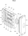
- a light source 270 illustrated in FIG. 5 and FIG. 6 can be used as each of the first light source and the second light sources described above.
- the light source 270 itself has a waterproof structure that shields light emitting elements and a wiring substrate from water. In the following, the description of the same configuration as the configuration of the light source 170 will be omitted as appropriate.
- a recess 273a is defined by the surface of a holding member 273 and a wall portion 273b.
- a wiring substrate 271 is disposed in the recess 273a of the holding member 273.
- the light source 270 may include a frame member 288 disposed on the wall portion 273b of the holding member 273.
- the outer shape of the frame member 288 can be a rectangular frame shape in a plan view as viewed from a first surface 270a side of the light source 270.
- the cover glass 286 is interposed between the frame member 288 and the holding member 273.
- the frame member 288 is fixed to the holding member 273 by, for example, a screw while a peripheral portion of a surface 286a (opposite to a surface facing the wiring substrate 271) of the cover glass 286 is pressed toward the holding member 273.
- a cushioning material 287 is interposed between the peripheral portion of the surface 286a of the cover glass 286 and the frame member 288.
- the frame member 288 may be fixed by an adhesive.
- the light-reflecting member 178 as illustrated in FIG. 4B may be disposed in the recess 273a.
- a cylindrical portion 273c in which a first through hole 273d leading into the recess 273a is formed is provided on one lateral surface of the wall portion 273b defining the recess 273a of the holding member 273.
- the light source 270 can be used as the first light source and disposed in the first light source placement portion 13 through the first opening 13a illustrated in FIG. 2 . Further, the light source 270 can be used as each of the second light sources and disposed in the corresponding second light source placement portion 16 through the second opening 16a illustrated in FIG. 2 . In a state in which the light source 270 is disposed in the first light source placement portion 13, the first opening 13a is covered by a waterproof cap 291 illustrated in FIG. 5 . A waterproof ring 292 is interposed between the waterproof cap 291 and the inner wall of the first opening 13a.
- the waterproof cap 291 has a second through hole 291a.
- the opening shape of the second through hole 291a is preferably substantially the same as that of the cylindrical portion 273c as viewed from the opening direction of the first through hole 273d of the light source 270.
- the cylindrical portion 273c of the holding member 273 fits into the second through hole 291a.
- a waterproof ring 284 is interposed between the cylindrical portion 273c and the inner wall of the second through hole 291a.
- an electrical cable electrically connected to wiring 274 of the wiring substrate 271 can be disposed on the surface of the wiring substrate 171. In this case, the electrical cable can be pulled out to the outside of the light source 270 through the first through hole 273d of the holding member 273 and the second through hole 291a of the waterproof cap 291.
- a portion of fluid flowing through the inside of the ultraviolet light fluid treatment device 1 or 2 is retained, and thus the integrated luminance of ultraviolet light emitted to the fluid increases in accordance with the retention time.
- the effect of treating the fluid with the ultraviolet light can be enhanced.
- This fluid retention will be described in detail below.
- the ultraviolet light fluid treatment device 1 is exemplified; however, effects of fluid retention can be similarly obtained in any of the ultraviolet light fluid treatment devices 1 and 2.
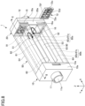
- FIG. 7 and FIG. 8 are drawings illustrating the first example of fluid retention.
- FIG. 7 is a cross-sectional view of the ultraviolet light fluid treatment device 1.
- FIG. 8 is a perspective view of the ultraviolet light fluid treatment device 1.
- An end portion 91 on the outlet 15 side of the merged flow channel 90 has an opening having a cross-sectional area smaller than the cross-sectional area of the merged flow channel 90 in the direction orthogonal to the first direction d1.
- a portion of fluid flowing in the merged flow channel 90 from the inlet 11 side toward the outlet 15 side in the X-axis direction is retained by hitting and bouncing back from the end portion 91 on the outlet 15 side of the merged flow channel 90.
- Flows 92 indicated by bold arrows in FIG. 7 and FIG. 8 represent the flows of the fluid bounced back from the end portion 91.
- such flows 92 increase the time during which a portion of the fluid flowing in the merged flow channel 90 is retained in the vicinity of the end portion 91.
- the flows 92 in FIG. 7 and FIG. 8 are examples illustrated for convenience of description, and the directions and the magnitudes of the flows are not limited thereto.
- the first light source 71 is disposed to face the end portion 91, and thus, the fluid retained in the vicinity of the end portion 91 is efficiently irradiated with ultraviolet light from the first light source 71.
- the integrated luminance of the ultraviolet light emitted from the first light source 71 to the fluid retained in the vicinity of the end portion 91 increases in accordance with the retention time. Accordingly, the ultraviolet light fluid treatment device 1 can enhance the treatment effect with the ultraviolet light.
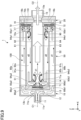
- FIG. 9 is a cross-sectional view of the ultraviolet light fluid treatment device 1, which illustrates a second example of fluid retention.
- a portion of fluid flowing in the branch flow channels 80a and 80b in the X-axis direction generates a vortex in turning back portions of the branch flow channels 80a and 80b.
- vortex refers to a swirling-like flow of fluid.
- a turning back portion 93a1 indicated by a dashed line is a turning back portion from the first flow channel 81a to the second flow channel 82a in the branch flow channel 80a.
- a vortex 94a1 indicated by a bold arrow represents a vortex generated in the vicinity of the turning back portion 93a1 in the second flow channel 82a.
- the turning back portion refers to a portion in which the fluid flowing in a predetermined direction turns back in a direction opposite to the predetermined direction.
- a turning back portion 93a2 is a turning back portion from the second flow channel 82a in the branch flow channel 80a to the merged flow channel 90.
- a vortex 94a2 represents a vortex generated in the vicinity of the turning back portion 93a2 in the merged flow channel 90.
- a turning back portion 93b1 is a turning back portion from the first flow channel 81b to the second flow channel 82b in the branch flow channel 80b.
- a vortex 94b1 represents a vortex generated in the vicinity of the turning back portion 93b1 in the second flow channel 82b.
- a turning back portion 93b2 is a turning back portion from the second flow channel 82b to the merged flow channel 90 in the branch flow channel 80b.
- a vortex 94b2 represents a vortex generated in the vicinity of the turning back portion 93b2 in the merged flow channel 90.
- the cross-sectional shape of the ultraviolet light fluid treatment device 1 orthogonal to the direction in which the fluid flows is a substantially rectangular shape.
- vortices are likely to occur at the turning back portions 93a1, 93a2, 93b1, and 93b2 near corner portions.
- corner portion refers to a portion where surfaces meet.
- the generation of vortices such as the vortices 94a1, 94a2, 94b1, and 94b2 increases the time during which a portion of the fluid flowing in the branch flow channels 80a and 80b is retained in the vicinity of each of the turning back portions 93a1, 93a2, 93b1, 93b2.
- the vortices 94a1, 94a2, 94b1, and 94b2 in FIG. 9 are examples illustrated for convenience of description, and the directions and the magnitudes of the vortices are not limited thereto.
- the first light source 71 is disposed in the vicinity of each of the turning back portions 93a2 and 93b2, and thus the fluid retained in the vicinity of each of the turning back portions 93a2 and 93b2 is efficiently irradiated with the ultraviolet light from the first light source 71.
- the second light sources 72 are disposed in the vicinities of the turning back portions 93a1 and 93b1, and thus the fluid retained in the vicinities of the turning back portions 93a1 and 93b1 is efficiently irradiated with the ultraviolet light from the second light sources 72.
- the integrated luminance of the ultraviolet light from the first light source 71 and the second light sources 72 to the fluid retained in the vicinities of the turning back portions 93a1, 93a2, 93b1, and 93b2 increases in accordance with the retention time. Accordingly, the ultraviolet light fluid treatment device 1 can enhance the effect of treating the fluid with the ultraviolet light.
- the ultraviolet light fluid treatment device 1 can enhance the effect of treating the bacteria and viruses in the water with the ultraviolet light.
- the ultraviolet light fluid treatment device 1 including the plurality of branch flow channels 80a and 80b is exemplified; however, the configuration is not limited thereto. Even when the ultraviolet light fluid treatment device 1 includes one branch flow channel, the effects described in the second example can be obtained.
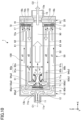
- FIG. 10 is a cross-sectional view of the ultraviolet light fluid treatment device 1, which illustrates a third example of fluid retention.
- a vortex is likely to be generated.
- the direction orthogonal to the direction in which the fluid flows is, for example, a direction along the Y-axis or a direction along the Z-axis. Accordingly, in the ultraviolet light fluid treatment device 1, the width w1 along the Y-axis may be greater than the width w2 along the Y-axis, or the width w1 along the Z-axis may be greater than the width w2 along the Z-axis.
- a flow rate difference or a flow velocity difference occurs between the fluid flowing in each of the branch flow channels 80a and 80b and the fluid flowing in the merged flow channel 90. Because of this flow rate difference or flow velocity difference, a vortex is more likely to be generated in the vicinity of each of the turning back portions 93a2 and 93b2, thereby increasing the retention time of the fluid in the vicinity of each of the turning back portions 93a2 and 93b2.
- a flow rate difference or a flow velocity difference occurs between the fluid flowing in each of the branch flow channels 80a and 80b and the fluid flowing in the merged flow channel 90. Because of this flow rate difference or flow velocity difference, a vortex is more likely to be generated in the vicinity of each of the turning back portions 93a2 and 93b2, thereby increasing the retention time of the fluid in the vicinity of each of the turning back portions 93a2 and 93b2.
- the vortex 94a2 represents a vortex generated in the vicinity of the turning back portion 93a2 in the merged flow channel 90
- the vortex 94b2 represents a vortex generated in the vicinity of the turning back portion 93b2 in the merged flow channel 90.
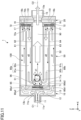
- FIG. 11 is a cross-sectional view of the ultraviolet light fluid treatment device 1, which illustrates a fourth example of fluid retention.
- FIG. 11 when the ultraviolet light fluid treatment device 1 is disposed such that the branch flow channel 80b is positioned vertically below the branch flow channel 80a, a vortex is likely to be generated in the vicinity of a merging portion 95 located on the inlet 11 side of the merged flow channel 90.
- the Z-axis is in the vertical direction.
- a flow rate difference or a flow velocity difference occurs between the fluid flowing from the branch flow channel 80a into the merged flow channel 90 and the fluid flowing from the branch flow channel 80b into the merged flow channel 90 by the action of gravity.
- the flow rate of the fluid flowing from the branch flow channel 80a into the merged flow channel 90 increases relative to the flow rate of the fluid flowing from the branch flow channel 80b into the merged flow channel 90 by the action of gravity. Because of this flow rate difference or flow velocity difference, a vortex is more likely to be generated in the vicinity of the merging portion 95 where the fluid merges, thereby increasing the retention time of the fluid in the vicinity of the merging portion 95.
- a vortex 96 represents a vortex generated in the vicinity of the merging portion 95.
- the vortex 96 in FIG. 11 is an example illustrated for convenience of description, and the direction and the magnitude of the vortex are not limited thereto.
- the first light source 71 is disposed in the vicinity of the merging portion 95, and thus the fluid retained in the vicinity of the merging portion 95 is efficiently irradiated with the ultraviolet light from the first light source 71.
- the integrated luminance of the ultraviolet light irradiated from the first light source 71 to the fluid retained in the vicinity of the merging portion 95 increases in accordance with the retention time. Accordingly, the ultraviolet light fluid treatment device 1 can enhance the treatment effect with the ultraviolet light.
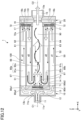
- FIG. 12 is a cross-sectional view of the ultraviolet light fluid treatment device 1, which illustrates a fifth example of fluid retention.
- a flow rate difference or a flow velocity difference occurs between the fluid flowing from the branch flow channel 80a into the merged flow channel 90 and the fluid flowing from the branch flow channel 80b into the merged flow channel 90.
- This flow rate difference or flow velocity difference causes the fluid to flow in a meandering manner in the merged flow channel 90 as illustrated in FIG. 12 .
- flows 97 represent the flows of the fluid flowing from the branch flow channels 80a and 80b into the merged flow channel 90
- a flow 98 represents the flow of the fluid flowing in the merged flow channel 90 in a meandering manner.
- the flow rate of the fluid flowing from the branch flow channel 80a into the merged flow channel 90 increases relative to the flow rate of the fluid flowing from the branch flow channel 80b into the merged flow channel 90 by the action of gravity.
- the fluid tends to flow vertically downward in the merged flow channel 90.
- a vector in the flow direction of the fluid from the inlet 11 toward the outlet 15 tends to be tilted with respect to the X-axis toward a branch flow channel having a lower flow rate of the branch flow channels 80a and 80b.
- the branch flow channel having a lower flow rate of the branch flow channels 80a and 80b is on the vertically downward side.
- the fluid flowing in the merged flow channel 90 with the vector in the flow direction being tilted vertically downward is bounced back vertically upward by the third partition member 63, then flows in the merged flow channel 90 with the vector in the flow direction being tilted vertically upward, and is subsequently bounced back vertically downward by the second partition member 62.
- the fluid flows in the merged flow channel 90 in a meandering manner.
- the meandering flow such as the flow 98 of the fluid is a phenomenon that is more pronounced when the branch flow channels 80a and 80b are separated from each other by the second partition member 62, the third partition member, and the like.
- a flow rate difference or a flow velocity difference occurs between the fluid flowing in the branch flow channel 80a and the fluid flowing in the branch flow channel 80b, thereby allowing the fluid to flow in a meandering manner as in the flow 98.
- a multi-tube structure can be configured in which the flow channels are formed concentrically.
- a flow rate difference or a flow velocity difference is less likely to occur in the fluid flowing in the flow channels. Therefore, in a configuration in which each of the flow channels has an annular shape, it would be difficult for the fluid to flow in a meandering manner as in the flow 98.
- the first light source 71 is disposed such that the ultraviolet light from the first light source 71 is efficiently emitted to the fluid flowing in the merged flow channel 90.
- the retention time increases, thereby increasing the integrated luminance. Accordingly, the ultraviolet light fluid treatment device 1 can enhance the treatment effect with the ultraviolet light.
- the ultraviolet light fluid treatment device 1 can increase the integrated luminance of the ultraviolet light emitted to the bacteria and viruses in the water, and can enhance the treatment effect with the ultraviolet light.
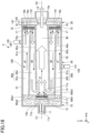
- FIG. 13 is a cross-sectional view of the ultraviolet light fluid treatment device 1, which illustrates a sixth example of fluid retention.
- the width of at least one of the plurality of branch flow channels in a direction orthogonal to the direction in which the fluid flows differs from the width of any other branch flow channel of the plurality of branch flow channels in the direction orthogonal to the direction in which the fluid flows.
- a width w3 of the branch flow channel 80a differs from a width w4 of the branch flow channel 80b in the direction orthogonal to the direction in which the fluid flows.
- the direction orthogonal to the direction in which the fluid flows is, for example, a direction along the Y-axis or a direction along the Z-axis. Accordingly, in the ultraviolet light fluid treatment device 1, the width w3 along the Y-axis and the width w4 along the Y-axis may differ, or the width w3 along the Z-axis and the width w4 along the Z-axis may differ.
- the installation orientation of the ultraviolet light fluid treatment device 1 is not particularly limited. This is also true for the other examples of fluid retention, except for the fourth example and the fifth example.
- FIG. 13 illustrates a configuration in which the width w3 of the second flow channel 82a in branch flow channel 80a is smaller than the width w4 of the second flow channel 82b in the branch flow channel 80b, thereby making the widths different from each other; however, the configuration is not limited thereto.
- the width w3 of the second flow channel 82a may be greater than the width w4 of the second flow channel 82b, thereby making the widths different from each other.
- the width of the first flow channel 81a in the branch flow channel 80a may differ from the width of the first flow channel 81b in the branch flow channel 80b in the direction orthogonal to the direction in which the fluid flows.
- the width of the first flow channel 81a and the width of the second flow channel 82a are the same in the direction orthogonal to the direction in which the fluid flows, but may differ from each other. Further, the width of the first flow channel 81b and the width of the second flow channel 82b are the same, but may differ from each other.
- a flow rate difference or a flow velocity difference occurs between the fluid flowing from the branch flow channel 80a into the merged flow channel 90 and the fluid flowing from the branch flow channel 80b into the merged flow channel 90.
- the width w3 to be smaller than the width w4
- the flow rate of the fluid flowing from the branch flow channel 80a into the merged flow channel 90 decreases as compared to the flow rate of the fluid flowing from the branch flow channel 80b into the merged flow channel 90.
- a vortex is more likely to occur in the vicinity of the merging portion 95 where the fluid merges, thereby increasing the retention time of the fluid in the vicinity of the merging portion 95.
- the fluid flows in a meandering manner in the merged flow channel 90, thereby increasing the retention time of the fluid in the merged flow channel 90.
- Effects resulting from a vortex such as the vortex 96 in the merging portion 95 are similar to those described in the above fourth example. Further, effects resulting from a meandering flow such as the flow 98 of the fluid in the merged flow channel 90 are similar to those described in the above fifth example.
- the two branch flow channels 80a and 80b are exemplified as the plurality of branch flow channels; however the configuration is not limited thereto. If the ultraviolet light fluid treatment device 1 includes three or more branch flow channels, the effects described in the sixth example can be obtained as long as the width of at least one of the three or more branch flow channels in the direction orthogonal to the direction in which the fluid flows differs from the width of any other branch flow channel in the direction orthogonal to the direction in which the fluid flows.
- FIG. 14 to FIG. 16 are drawings illustrating the ultraviolet light fluid treatment device 1, which illustrates a seventh example of fluid retention.
- FIG. 14 is a side view of the ultraviolet light fluid treatment device 1 as viewed from the inlet 11 side.
- FIG. 15 is a cross-sectional view of the ultraviolet light fluid treatment device 1 taken through XV-XV of FIG. 14 .
- FIG. 16 is a cross-sectional view of the ultraviolet light fluid treatment device 1 taken through XVI-XVI of FIG. 15 , as viewed from the outlet 15 side.
- white arrows indicate flows, serving as primary flows, of portions of fluid flowing into the ultraviolet light fluid treatment device 1 through the inlet 11 and flowing out of the ultraviolet light fluid treatment device 1 through the outlet 15. Further, in FIG. 14 to FIG. 16 , dot-hatched arrows indicate flows of portions of the fluid used to cool the second light sources 72, of the fluid flowing through the ultraviolet light fluid treatment device 1.
- a vortex is more likely to occur when a width w5 of the branch flow channel 80a in a direction orthogonal to the extending direction of the branch flow channels 80a and 80b differs from a width w6 of the turning back portions 93a2 and 93b2 in a direction along the extending direction of the branch flow channels 80a and 80b.
- the extending direction of the branch flow channels 80a and 80b is, for example, a direction along the X-axis.
- the direction orthogonal to the extending direction of the branch flow channels 80a and 80b is, for example, a direction along the Y-axis or a direction along the Z-axis. Therefore, in the ultraviolet light fluid treatment device 1, the width w5 along the Y-axis and the width w6 along the X-axis may differ from each other, or the width w5 along the Z-axis and the width w6 along the X-axis may differ from each other.
- a flow rate difference or a flow velocity difference occurs between the fluid flowing in the branch flow channels 80a and 80b and the fluid flowing in the turning back portions 93a2 and 93b2. Because of this flow rate difference or flow velocity difference, a vortex is more likely to occur in the vicinity of each of the turning back portions 93a2 and 93b2, thereby increasing the retention time of the fluid in the vicinity of each of the turning back portions 93a2 and 93b2.
- the length of each of the first flow channels 81a and 81b and the second flow channels 82a and 82b in the X-axis direction is 200 mm, for example.
- the width of each of the first flow channels 81a and 81b and the second flow channels 82a and 82b in the Z-axis direction is, for example, 24 mm.
- the width of each of the first flow channels 81a and 81b and the second flow channels 82a and 82b in the Y-axis direction is, for example, 50 mm.
- the flow rate of the fluid flowing through the ultraviolet light fluid treatment device 1 illustrated in FIG. 15 is preferably 3 m 3 /h or more.
- the ultraviolet light fluid treatment device 1 can increase the integrated luminance of the ultraviolet light, and can enhance the treatment effect with the ultraviolet light. Further, in the ultraviolet light fluid treatment device 1, a decrease in heat transfer efficiency due to air bubbles entering the downstream flow channel 110 can be suppressed, and a decrease in cooling efficiency of the second light sources 72 due to the fluid flowing in the downstream flow channel 110 can be suppressed.
- the dimensions of the ultraviolet light fluid treatment device 1 and the flow rate of the fluid are not limited to the above.
- the ultraviolet light fluid treatment device is not used for a certain period of time while liquid is contained inside the device, mold and bacteria may grow inside the device. Such mold and bacteria would decrease the treatment effect of the ultraviolet light fluid treatment device. Therefore, in order to prevent the growth of mold and bacteria, the liquid inside the ultraviolet light fluid treatment device is preferably drained periodically or before a period of non-usage, such that no liquid remains in the device, that is, the ultraviolet light fluid treatment device is emptied.
- the ultraviolet light fluid treatment device includes a drain port on the lower side in the vertical direction.
- the drain port is configured to discharge liquid inside the device to the outside.
- partition members that partition flow channels of the liquid are inclined with respect to the horizontal direction orthogonal to the vertical direction.
- FIG. 17 is a cross-sectional view of an ultraviolet light fluid treatment device 3 according to the third embodiment of the present invention.
- the ultraviolet light fluid treatment device 3 includes a drain port 120, a drain mechanism 121, and a plurality of partition members 61a to 64a.
- the plurality of partition members 61a to 64a for example, four partition members (a first partition member 61a, a second partition member 62a, a third partition member 63a, and a fourth partition member 64a) are disposed in the intermediate portion 50.
- the drain port 120 is a through hole formed in the second wall 52 located on the lower side in the vertical direction of the intermediate portion 50 in the ultraviolet light fluid treatment device 3.
- the drain port 120 can be opened and closed by a plug. In a state in which the plug of the drain port 120 is opened, the liquid inside the ultraviolet light fluid treatment device 3 flows vertically downward by the action of gravity and is discharged through the drain port 120. In a state in which the plug of the drain port 120 is closed, the liquid inside the ultraviolet light fluid treatment device 3 is not discharged.
- the position where the drain port 120 is formed is not particularly limited as long as the drain port 120 is formed in the second wall 52.
- the drain mechanism 121 is a mechanism that can adjust the amount of liquid discharged from the drain port 120.
- the drain mechanism 121 is a drain device including a plug that can adjust opening and closing of the drain port 120.
- the amount of liquid discharged from the drain port 120 can be adjusted by adjusting opening and closing of the plug of the drain device in the ultraviolet light fluid treatment device 3.
- the drain mechanism 121 is not an essential component; however, the ultraviolet light fluid treatment device 3 preferably includes the drain mechanism 121 from the viewpoint of improving the workability of a drain operation.
- the shape, the arrangement position, and the support method of the first partition member 61a are the same as those of the first partition member 61 according to the first embodiment.
- the first partition member 61a differs from the first partition member 61 in that the first partition member 61a is inclined at an angle ⁇ 1 with respect to the X-axis direction.
- the X-axis direction is orthogonal to the Z-axis direction, and corresponds to the horizontal direction orthogonal to the vertical direction.
- the first partition member 61a is inclined at the angle ⁇ 1
- the height of the surface of the first partition member 61a in the vertical direction decreases along a direction of the arrow of the X-axis.
- the shape, the arrangement position, and the support method of the second partition member 62a are the same as those of the second partition member 62 according to the first embodiment.
- the second partition member 62a differs from the second partition member 62 in that the second partition member 62a is inclined at an angle ⁇ 2 with respect to the X-axis direction.
- the second partition member 62a is inclined at the angle ⁇ 2
- the height of the surface of the second partition member 62a in the vertical direction decreases along a direction opposite to the direction of the arrow of the X-axis.
- the shape, the arrangement position, and the support method of the third partition member 63a are the same as those of the third partition member 63 according to the first embodiment.
- the third partition member 63a differs from the third partition member 63 in that the third partition member 63a is inclined at an angle ⁇ 3 with respect to the X-axis direction.
- the third partition member 63a is inclined at the angle ⁇ 3
- the height of the surface of the third partition member 63a in the vertical direction decreases along the direction opposite to the direction of the arrow of the X-axis.
- the shape, the arrangement position, and the support method of the fourth partition member 64a are the same as those of the fourth partition member 64 according to the first embodiment.
- the fourth partition member 64a differs from the fourth partition member 64 in that the fourth partition member 64a is inclined at an angle ⁇ 4 with respect to the X-axis direction.
- the fourth partition member 64a is inclined at the angle ⁇ 4
- the height of the surface of the fourth partition member 64a in the vertical direction decreases along the direction of the arrow of the X-axis.
- each of the angle ⁇ 1, the angle ⁇ 2, the angle ⁇ 3, and the angle ⁇ 4 is not particularly limited and can be appropriately selected.
- each of the angle ⁇ 1, the angle ⁇ 2, the angle ⁇ 3, and the angle ⁇ 4 is approximately 1° from the viewpoint of satisfying the drainage requirements in Good Manufacturing Practice (GMP) standards.
- GMP Good Manufacturing Practice
- the plug of the drain mechanism 121 is opened, and as a result, the liquid in the first flow channel 81b is discharged vertically downward from the drain port 120 of the ultraviolet light fluid treatment device 3 by the action of gravity.
- the liquid in the second flow channel 82b flows toward the first flow channel 81b along the fourth partition member 64a.
- the height of the surface of the fourth partition member 64a in the vertical direction decreases along the direction of the arrow of the X-axis. For this reason, the liquid in the second flow channel 82b easily flows toward the first flow channel 81b along the fourth partitioning member 81b by the action of gravity, and is less likely to remain on the fourth partitioning member 64a.
- the liquid in the merged flow channel 90 flows toward the second flow channel 82b along the third partition member 63a.
- the height of the surface of third partition member 63a in the vertical direction decreases along the direction opposite to the direction of the arrow of the X-axis. For this reason, the liquid in the merged flow channel 90 easily flows toward the second flow channel 82b along the third partition member 63a by the action of gravity, and is less likely to remain on the third partition member 63a.
- the liquid in the second flow channel 82a flows toward the merged flow channel 90 along the second partition member 62a.
- the height of the surface of second partition member 62a in the vertical direction decreases along the direction opposite to the direction of the arrow of the X-axis. For this reason, the liquid in the second flow channel 82a easily flows toward the merged flow channel 90 along the second partition member 62a by the action of gravity, and is less likely to remain on the second partition member 62a.
- the liquid in the first flow channel 81a flows toward the second flow channel 82a along the first partition member 61a.
- the height of the surface of first partition member 61a in the vertical direction decreases along the direction of the arrow of the X-axis. For this reason, the liquid in the first flow channel 81a easily flows toward the second flow channel 82a along the first partition member 61a by the action of gravity, and is less likely to remain on the first partition member 61a.
- the liquid inside the ultraviolet light fluid treatment device 3 when the liquid inside the ultraviolet light fluid treatment device 3 is discharged to empty the device, the liquid inside the device can be easily discharged from the drain port 120 to the outside, thereby allowing the liquid to be less likely to remain in the device.
- a first downstream end 131 is an end of the first partition member 61a on the downstream side in the direction in which the liquid flows. There may be a gap along the X-axis direction between the first downstream end 131 and the surface of the first end portion 10 facing the first downstream end 131.
- the liquid inside the device is discharged to empty the device, the liquid easily flows vertically downward through the gap as compared when there is no gap. Thus, the presence of the gap is preferable.
- the length of the gap along the X-axis direction between the first downstream end 131 and the surface of the first end portion 10 is not particularly limited, as long as fluid can pass through the gap. However, if the gap is too large, the treatment effect of the ultraviolet light fluid treatment device 3 would be decreased due to the fluid passing through the gap during treatment. Therefore, the length of the gap along the X-axis direction is preferably approximately 1 mm or more and 5 mm or less.
- a second downstream end 132 is an end of the second partition member 62a on the downstream side in the direction in which the fluid flows. Similar to the first downstream end 131, there may be a gap along the X-axis direction between the second downstream end 132 and the surface of the second end portion 20 facing the second downstream end 132. Functions and effects of this gap are the same as those of the first downstream end 131.
- a third downstream end 133 is an end of the third partition member 63a on the downstream side in the direction in which the fluid flows. Similar to the first downstream end 131, there may be a gap along the X-axis direction between the third downstream end 133 and the surface of the second end portion 20 facing the third downstream end 133. Functions and effects of this gap are the same as those of the first downstream end 131.
- a fourth downstream end 134 is an end of the fourth partition member 64a on the downstream side in the direction in which the fluid flows. Similar to the first downstream end 131, there may be a gap along the X-axis direction between the fourth downstream end 134 and the surface of the first end portion 10 facing the fourth downstream end 134. Functions and effects of this gap are the same as those of the first downstream end 131.
- the ultraviolet light fluid treatment device In the ultraviolet light fluid treatment device, if air bubbles are included in liquid flowing in the flow channels of the ultraviolet light fluid treatment device during treatment, the liquid would not be subjected to the treatment by the volume of the air bubbles, and thus the treatment efficiency of the ultraviolet light fluid treatment device would be decreased. Further, in the ultraviolet light fluid treatment device 1 of the first embodiment, if air bubbles are included in liquid flowing in the downstream flow channel 110, the cooling efficiency of the second light sources 72 would be decreased by the volume of the air bubbles.
- air bubble refers to gas in the liquid.
- the ultraviolet light fluid treatment device includes a first exhaust port configured to discharge air bubbles in liquid filled in the device, and a second exhaust port configured to discharge air bubbles in the liquid flowing in the downstream flow channel.
- the first exhaust port and the second exhaust port are disposed on the upper side in the vertical direction of the intermediate portion 50.
- the ultraviolet light fluid treatment device includes the first exhaust port, and thus air bubbles in the liquid filled in the device can be reduced. Therefore, a decrease in the treatment efficiency of the ultraviolet light fluid treatment device can be reduced.
- the ultraviolet light fluid treatment device includes the second exhaust port, and thus air bubbles in the liquid flowing in the downstream flow channel 110 can be reduced. Therefore, a decrease in the cooling efficiency of the second light sources 72 can be reduced.
- FIG. 18 is a cross-sectional view of an ultraviolet light fluid treatment device 4 according to the fourth embodiment of the present invention.
- the ultraviolet light fluid treatment device 4 includes a first exhaust port 130, a first exhaust mechanism 135, a second exhaust port 140, and a second exhaust mechanism 141.
- the first exhaust port 130 is a through hole formed in the first wall 51 located on the upper side in the vertical direction of the ultraviolet light fluid treatment device 4.
- the first exhaust port 130 can be opened and closed by a plug. In a state in which the plug of the first exhaust port 130 is opened, air bubbles in the liquid inside the ultraviolet light fluid treatment device 4 flow vertically upward by the action of buoyancy and are discharged through the first exhaust port 130. In a state in which the plug of the first exhaust port 130 is closed, air bubbles in the liquid inside the ultraviolet light fluid treatment device 4 are not discharged.
- the position where the first exhaust port 130 is formed is not particularly limited as long as the first exhaust port 130 is formed in the first wall 51.
- the first exhaust mechanism 135 is a mechanism that can adjust the amount of air bubbles discharged from the first exhaust port 130.
- the first exhaust mechanism 135 is a drain device including a plug that can adjust opening and closing of the first exhaust port 130.
- the amount of liquid discharged from the first exhaust port 130 can be adjusted by adjusting opening and closing of the plug of the ultraviolet light fluid treatment device 4.
- the first exhaust mechanism 135 is not an essential component; however, the ultraviolet light fluid treatment device 4 preferably includes the first exhaust mechanism 135 from the viewpoint of improving the workability of a drain operation.
- the second exhaust port 140 is a through hole formed in the second end portion 20 on the upper side in the vertical direction of the ultraviolet light fluid treatment device 4.
- the second exhaust port 140 can be opened and closed by a plug. In a state in which the plug of the second exhaust port 140 is opened, air bubbles in the liquid inside the ultraviolet light fluid treatment device 4 flow vertically upward by the action of buoyancy and are discharged through the second exhaust port 140. In a state in which the plug of the second exhaust port 140 is closed, air bubbles in the liquid inside the ultraviolet light fluid treatment device 4 are not discharged.
- the position where the second exhaust port 140 is formed is not particularly limited as long as the second exhaust port 140 is formed in second end portion 20 on the upper side in the vertical direction.
- the second exhaust mechanism 141 is a mechanism that can adjust the amount of air bubbles discharged from the second exhaust port 140.
- the second exhaust mechanism 141 is a drain device including a plug that can adjust opening and closing of the second exhaust port 140.
- the amount of liquid discharged from the second exhaust port 140 can be adjusted by adjusting opening and closing of the plug of the ultraviolet light fluid treatment device 4.
- the second exhaust mechanism 141 is not an essential component; however, the ultraviolet light fluid treatment device 4 preferably includes the second exhaust mechanism 141 from the viewpoint of improving the workability of a drain operation.
- the ultraviolet light fluid treatment device 4 includes the first exhaust port 130.
- air bubbles in the liquid filled in the device can be reduced. Accordingly, a decrease in the treatment efficiency of the ultraviolet light fluid treatment device 4 can be reduced.
- the ultraviolet light fluid treatment device 4 includes the second exhaust port 140.
- air bubbles in the liquid flowing in the downstream flow channel 110 can be reduced. Accordingly, a decrease in the cooling efficiency of the second light sources 72 can be reduced.
- FIG. 19 is a drawing illustrating a plurality of partition members 61b to 64b included in an ultraviolet light fluid treatment device 5 according to a fifth embodiment of the present invention.
- FIG. 19 illustrates the intermediate portion 50 extracted from the ultraviolet light fluid treatment device 5.
- the plurality of partition members 61a to 64a for example, four partition members (a first partition member 61b, a second partition member 62b, a third partition member 63b, and a fourth partition member 64b) are disposed in the intermediate portion 50.
- a plurality of first openings 151 is formed in the first partition member 61b. Each of the first openings 151 is a hole penetrating the first partition member 61b in the thickness direction of the first partition member 61b.
- a plurality of second openings 152 is formed in the second partition member 62b. Each of the second openings 152 is a hole penetrating the second partition member 62b in the thickness direction of the second partition member 62b.
- a plurality of third openings 153 is formed in the third partition member 63b. Each of the third openings 153 is a hole penetrating the third partition member 63b in the thickness direction of the third partition member 63b.
- a plurality of fourth openings 154 is formed in the fourth partition member 64b.
- Each of the fourth openings 15 is a hole penetrating the fourth partition member 64b in the thickness direction of the fourth partition member 64b.
- openings 150 when the plurality of first openings 151, the plurality of second openings 152, the plurality of third openings 153, and the plurality of fourth openings 154 are not particularly distinguished, they are collectively referred to as openings 150.
- the ultraviolet light fluid treatment device 5 has the openings 150.
- the ultraviolet light fluid treatment device 5 has the openings 150, and thus air bubbles in the liquid inside the device can easily move vertically upward through the openings 150. Accordingly, air bubbles in the liquid filled in the device can be reduced, and a decrease in the treatment efficiency of the ultraviolet light fluid treatment device 5 can be reduced.
- the shape of the openings 150 in a top view is not particularly limited, and any shape such as a circular shape, an elliptical shape, a rectangular shape, or a polygonal shape can be appropriately selected. Further, the number, positions, intervals, and the like of the openings 150 can be appropriately selected. Openings 150 may be formed only in a portion of each of the first partition member 61b, the second partition member 62b, the third partition member 63b, and the fourth partition member 64b. With this configuration, in addition to effects of reducing residual liquid and reducing air bubbles as described above, an effect of smoothing the flow of fluid in the flow channel 100 of the ultraviolet light fluid treatment device 5, in other words, an effect of regulating the flow of the fluid can be obtained.
- FIG. 20 is a perspective view of a light source 170 including a photodetector 180 in the ultraviolet light fluid treatment device 6.
- FIG. 21 and FIG. 22 are drawings illustrating the operation of the photodetector 180.
- FIG. 21 is a first drawing and FIG. 22 is a second drawing.
- the ultraviolet light fluid treatment device 6 includes the photodetector 180.
- the photodetector 180 is provided on a first surface 170a of the light source 170.
- the installation position of the photodetector 180 can be appropriately changed as long as the photodetector 180 is provided within a region surrounded by a light-reflecting member 178.
- the photodetector 180 includes a light receiving element that receives ultraviolet light, and outputs information corresponding to the light intensity of the received ultraviolet light to an external device.
- the light receiving element include a photoelectric conversion element such as a photodiode.
- the photodetector 180 can output information corresponding to the light intensity of ultraviolet light having a wavelength of 265 nm, 280 nm, or the like.
- the output information from the photodetector 180 is a voltage signal, a current signal, or the like.
- the external device is a control device or the like that controls the operation of the ultraviolet light fluid treatment device 6.
- a portion of ultraviolet light, emitted from a second light source 72 of the two second light sources 72 toward the corresponding second window 17, is transmitted through the second window 17 and is emitted into the flow channel 100, and the other portion of the ultraviolet light is reflected by the second window 17 toward a photodetector 180.
- the photodetector 180 receives the ultraviolet light emitted from the second light source 72 and reflected by the second window 17.
- the photodetector 180 outputs information corresponding to the light intensity of the received ultraviolet light.
- the light intensity of the ultraviolet light emitted from the second light source 72 decreases due to deterioration of the second light source 72 according to a use period or the like of the second light source 72. If the light intensity of the ultraviolet light decreases, the treatment effect of the ultraviolet light fluid treatment device would decrease.
- output information from the photodetector 180 includes information indicating a decrease in the light intensity of the ultraviolet light emitted from the second light source 72.
- This output information allows the ultraviolet light fluid treatment device 6 to provide a notification indicating the deterioration of the second light source 72 to the external device.
- the external device can control the drive signal of the second light source 72 according to the degree of the deterioration of the second light source 72, and can notify a user or the like who uses the ultraviolet light fluid treatment device 6 of information prompting the user to replace the second light source 72.
- the photodetector 180 provided on the second light source 72 is illustrated in FIG. 21 ; however, the same effects as those described above can be obtained by providing the photodetector 180 on the first light source 71.
- the photodetector 180 can detect not only the deterioration of the light source 170 but also the state of contamination of the flow channel 100.
- a portion of a flow channel may be contaminated due to adhesion of foreign matter to the surface of a window such as the second window 17. If the flow channel is contaminated, ultraviolet light emitted from a light source such as the second light source 72 toward fluid flowing in the flow channel would be blocked or absorbed by the contaminated portion, and as a result, the treatment effect of the ultraviolet light fluid treatment device would decrease.
- a portion of the ultraviolet light emitted from the second light source 72 toward the second window 17 is transmitted through the second window 17 and is emitted into the flow channel 100.
- a portion of the emitted light is reflected by the end portion of the first partition member 61, is transmitted through the second window 17 from the flow channel 100 side to the second light source 72 side, and reaches the photodetector 180 provided on the second light source 72.
- Reflected light 190 indicated by an arrow represents the ultraviolet light reflected by the end portion of the first partition member 61.
- output information from the photodetector 180 includes information indicating that the flow channel 100 is contaminated. This output information allows the ultraviolet light fluid treatment device 6 to provide a notification indicating the contamination of the flow channel 100 to the external device. Based on the output information from the ultraviolet light fluid treatment device 6, the external device can control the drive signal of the second light source 72 according to the degree of the contamination of the flow channel 100, and can notify the user or the like who uses the ultraviolet light fluid treatment device 6 of information prompting the user to clean the flow channel 100.
- the ultraviolet light fluid treatment device 6 may include a reflective member 191 in the merged flow channel 90, in order to detect contamination of the flow channel 100 due to adhesion of foreign matter to the surface of a first window 14.
- the shape, the position, the material, and the like of the reflective member 191 are not limited as long as the reflective member 191 can reflect the ultraviolet light; however, the reflective member 191 preferably has a small influence on the flow of the fluid in the merged flow channel 90.
- a portion of the ultraviolet light is reflected by the reflective member 191, is transmitted through the first window 14 from the flow channel 100 side to the first light source 71 side, and reaches a photodetector 180.
- Reflected light 192 indicated by an arrow represents the ultraviolet light reflected by the reflective member 191.
- the ultraviolet light fluid treatment device 6 can detect contamination of the flow channel 100 due to adhesion of foreign matter to the surface of the first window 14, and can output, to the external device, output information including information indicating that the flow channel 100 is contaminated. Based on the output information from the ultraviolet light fluid treatment device 6, the external device can control the drive signal of the first light source 71 according to the degree of the contamination of the flow channel 100, and can notify the user or the like who uses the ultraviolet light fluid treatment device 6 of information prompting the user to clean the flow channel 100.
- the fluid entering the merged flow channel 90 flows into each of the outlet 15 and the downstream flow channel 110; however, all of the fluid entering the merged flow channel 90 may flow into the downstream flow channel 110.
- the fluid entering the merged flow channel 90 flows into each of the outlet 15 and the downstream flow channel 110, there may be a case where the fluid does not reach the vicinity of each of the upper and lower ends in the vertical direction of the downstream flow channel 110. In the regions where the fluid does not reach, cooling effects of the second light sources 72 may be insufficient.
- the fluid By allowing all of the fluid entering the merged flow channel 90 to flow into the downstream flow channel 110, the fluid can reach the vicinity of each of the upper and lower ends in the vertical direction of the downstream flow channel 110. Accordingly, cooling effects of the second light sources 72 can be appropriately obtained.
Landscapes
- Health & Medical Sciences (AREA)
- Life Sciences & Earth Sciences (AREA)
- General Health & Medical Sciences (AREA)
- Animal Behavior & Ethology (AREA)
- Veterinary Medicine (AREA)
- Public Health (AREA)
- Epidemiology (AREA)
- Chemical & Material Sciences (AREA)
- Toxicology (AREA)
- Organic Chemistry (AREA)
- Environmental & Geological Engineering (AREA)
- Water Supply & Treatment (AREA)
- Engineering & Computer Science (AREA)
- Hydrology & Water Resources (AREA)
- Physics & Mathematics (AREA)
- Electromagnetism (AREA)
- Chemical Kinetics & Catalysis (AREA)
- Physical Water Treatments (AREA)
- Apparatus For Disinfection Or Sterilisation (AREA)
- Physical Or Chemical Processes And Apparatus (AREA)
Abstract
Description
- The present invention relates to an ultraviolet light fluid treatment device.
- For example,
Patent Document 1 discloses a device that emits ultraviolet light from a light emitting element into a flow channel in which fluid flows. - Patent Document 1:
Japanese Laid-open Patent Publication No. 2018-140001 - It is an object of the present invention to provide an ultraviolet light fluid treatment device that can enhance a treatment effect.
- According to an aspect of the present invention, an ultraviolet light fluid treatment device includes an inlet and an outlet of fluid; a flow channel connecting the inlet and the outlet and including a plurality of branch flow channels branching from the inlet, and a merged flow channel connected to a downstream side of each of the branch flow channels; a first light source configured to emit ultraviolet light to the merged flow channel; and a plurality of second light sources configured to emit the ultraviolet light to the plurality of respective branch flow channels.
- According to the present invention, an ultraviolet light fluid treatment device that can enhance a treatment effect can be provided.
-
- [
FIG. 1] FIG. 1 is a perspective view of an ultraviolet light fluid treatment device according to a first embodiment of the present invention; - [
FIG. 2] FIG. 2 is a cross-sectional view of the ultraviolet light fluid treatment device taken through line II-II ofFIG. 1 ; - [
FIG. 3] FIG. 3 is a cross-sectional view of an ultraviolet light fluid treatment device according to a second embodiment of the present invention; - [
FIG. 4A] FIG. 4A is a perspective view illustrating an example of a light source according to an embodiment of the present invention; - [
FIG. 4B] FIG. 4B is a perspective view illustrating another example of a light source according to an embodiment of the present invention; - [
FIG. 5] FIG. 5 is a perspective view illustrating another example of a light source according to an embodiment of the present invention; - [
FIG. 6] FIG. 6 is an exploded perspective view of the light source illustrated inFIG. 5 ; - [
FIG. 7] FIG. 7 is a cross-sectional view of the ultraviolet light fluid treatment device, which illustrates a first example of fluid retention; - [
FIG. 8] FIG. 8 is a perspective view of the ultraviolet light fluid treatment device, which illustrates the first example of fluid retention; - [
FIG. 9] FIG. 9 is a cross-sectional view of the ultraviolet light fluid treatment device, which illustrates a second example of fluid retention; - [
FIG. 10] FIG. 10 is a cross-sectional view of the ultraviolet light fluid treatment device, which illustrates a third example of fluid retention; - [
FIG. 11] FIG. 11 is a cross-sectional view of the ultraviolet light fluid treatment device, which illustrates a fourth example of fluid retention; - [
FIG. 12] FIG. 12 is a cross-sectional view of the ultraviolet light fluid treatment device, which illustrates a fifth example of fluid retention; - [
FIG. 13] FIG. 13 is a cross-sectional view of the ultraviolet light fluid treatment device, which illustrates a sixth example of fluid retention; - [
FIG. 14] FIG. 14 is a side view of the ultraviolet light fluid treatment device as viewed from the inlet side, which illustrates a seventh example of fluid retention; - [
FIG. 15] FIG. 15 is a cross-sectional view of the ultraviolet light fluid treatment device taken through XV-XV ofFIG. 14 ; - [
FIG. 16] FIG. 16 is a cross-sectional view of the ultraviolet light fluid treatment device taken through XVI-XVI ofFIG. 15 ; - [
FIG. 17] FIG. 17 is a cross-sectional view of an ultraviolet light fluid treatment device according to a third embodiment of the present invention; - [
FIG. 18] FIG. 18 is a cross-sectional view of an ultraviolet light fluid treatment device according to a fourth embodiment of the present invention; - [
FIG. 19] FIG. 19 is a drawing illustrating partition members included in an ultraviolet light fluid treatment device according to a fifth embodiment of the present invention; - [
FIG. 20] FIG. 20 is a perspective view of a light source including a photodetector in an ultraviolet light fluid treatment device according to a sixth embodiment of the present invention; - [
FIG. 21] FIG. 21 is a first diagram illustrating the operation of the photodetector ofFIG. 20 ; and - [
FIG. 22] FIG. 22 is a second diagram illustrating the operation of the photodetector ofFIG. 20 . - In the following, embodiments will be described with reference to the accompanying drawings. In the drawings, the same elements are denoted by the same reference numerals. Note that the drawings schematically illustrate the embodiments, and thus scales, intervals, positional relationships, and the like of members may be exaggerated, or illustration of some of the members may be omitted.
-
FIG. 1 is a perspective view of an ultraviolet lightfluid treatment device 1 according to a first embodiment of the present invention.FIG. 2 is a cross-sectional view of the ultraviolet lightfluid treatment device 1 taken through line II-II ofFIG. 1 . InFIG. 1 andFIG. 2 , three axes orthogonal to each other are defined as an X-axis, a Y-axis, and a Z-axis. The cross section illustrated inFIG. 2 is parallel to the X-axis and the Z-axis, and is orthogonal to the Y-axis. - The ultraviolet light
fluid treatment device 1 includes afirst end portion 10, asecond end portion 20, and anintermediate portion 50 located between thefirst end portion 10 and thesecond end portion 20. Further, the ultraviolet lightfluid treatment device 1 includes afirst light source 71 and asecond light source 72. In the example illustrated inFIG. 1 andFIG. 2 , thefirst light source 71 is disposed in thefirst end portion 10 and thesecond light source 72 is disposed in thesecond end portion 20. - The material of the
first end portion 10, thesecond end portion 20, and theintermediate portion 50 is metal, and is, for example, stainless steel. Thefirst end portion 10, thesecond end portion 20, and theintermediate portion 50 may be separated from one another, or may be integrated into one another. - In
FIG. 2 , the flows of fluid are indicated by bold arrows. The fluid such as liquid or gas flows into thefirst end portion 10 from the outside of the ultraviolet lightfluid treatment device 1. The fluid further flows from thefirst end portion 10 through theintermediate portion 50 to thesecond end portion 20, and flows out from thesecond end portion 20 to the outside of the ultraviolet lightfluid treatment device 1. - The
first end portion 10 includes aninlet 11 of the fluid, anupstream flow channel 12, a first lightsource placement portion 13, and afirst window 14. - The
inlet 11 includes a hole leading from the outside of the ultraviolet lightfluid treatment device 1 to the inside of thefirst end portion 10. An external pipe is connected to theinlet 11, and the fluid flows into theinlet 11 from the external pipe. The cross-sectional shape of theinlet 11 orthogonal to a direction in which the fluid flows is, for example, a circular shape. Theinlet 11 includes aninlet port 11a formed as a circular opening, for example. A central axis C1 passing through the center of the circular cross-sectional shape of theinlet 11 is parallel to the X-axis direction. - The
upstream flow channel 12 is connected to theinlet 11 within thefirst end portion 10. Theupstream flow channel 12 branches into a plurality of flow channels from theinlet 11. In the example illustrated inFIG. 2 , theupstream flow channel 12 branches into two flow channels from theinlet 11. For example, theupstream flow channel 12 branches from theinlet 11 in directions opposite to each other in the Z-axis direction that is orthogonal to the central axis C1. - The first light
source placement portion 13 is formed as a space within thefirst end portion 10 in which thefirst light source 71 can be disposed. As illustrated inFIG. 1 , afirst opening 13a leading to the first lightsource placement portion 13 is formed in alateral surface 10a of thefirst end portion 10. Thefirst light source 71 can be detachably attached to the first lightsource placement portion 13 through thefirst opening 13a. The first lightsource placement portion 13 is formed as a space separated from each flow channel of the ultraviolet lightfluid treatment device 1, and thefirst light source 71 is not exposed to the fluid and is protected from the fluid. For example, if the fluid is liquid, thefirst light source 71 does not require a waterproof structure. Further, thefirst light source 71 can be detached, replaced, and maintained while the fluid is flowing in the ultraviolet lightfluid treatment device 1. The first lightsource placement portion 13 may be provided within theintermediate portion 50. In this case, thefirst opening 13a leading to the first lightsource placement portion 13 is formed in athird wall 53 or afourth wall 54 of theintermediate portion 50 described later. - The
first light source 71 emits ultraviolet light. The peak wavelength of the ultraviolet light emitted from thefirst light source 71 is, for example, 10 nm or more and 400 nm or less. Thefirst light source 71 includes light emitting elements. As the light emitting elements, light emitting diodes (LEDs) or laser diodes (LDs) can be used, for example. As thefirst light source 71, a light emitting device in which light emitting elements are mounted on a wiring substrate, a light emitting device in which housings including light emitting elements are mounted on a wiring substrate, or the like can be used. Thefirst light source 71 has afirst surface 71a and asecond surface 71b located opposite to thefirst surface 71a. Thefirst surface 71a is a light emitting surface, and the ultraviolet light is emitted from thefirst surface 71a. - The
first window 14 is disposed to face thefirst surface 71a of thefirst light source 71. Thefirst surface 71a is located between thefirst window 14 and thesecond surface 71b of thefirst light source 71 in the X-axis direction, and a portion of theupstream flow channel 12 is located between thesecond surface 71b and theinlet 11 in the X-axis direction. Thefirst window 14 is formed of a material having transmissivity with respect to the wavelength of the light emitted from thefirst light source 71. Examples of the material of thefirst window 14 include inorganic materials formed of at least one material selected from the group consisting of quartz glass, borosilicate glass, calcium fluoride glass, aluminoborosilicate glass, oxynitride glass, chalcogenide glass, and sapphire. - The
second end portion 20 includes anoutlet 15 of the fluid, a second lightsource placement portion 16, and asecond window 17. - The
outlet 15 includes a hole leading from the inside of thesecond end portion 20 to the outside of the ultraviolet lightfluid treatment device 1. An external pipe is connected to theoutlet 15. The fluid flowing in the ultraviolet lightfluid treatment device 1 flows out from theoutlet 15 into the external pipe. The cross-sectional shape of theoutlet 15 orthogonal to the direction in which the fluid flows is, for example, a circular shape. Theoutlet 15 includes anoutlet port 15a formed as a circular opening, for example. - A central axis C2 passing through the center of the circular cross-sectional shape of the
outlet 15 preferably coincides with the central axis C1 of theinlet 11. Accordingly, the ultraviolet lightfluid treatment device 1 can be easily connected to an intermediate portion of a straight pipe that is generally available. - The second light
source placement portion 16 is formed as a space within thesecond end portion 20 in which the secondlight source 72 can be disposed. A plurality of secondlight sources 72 is disposed within thesecond end portion 20. In the present embodiment, for example, two secondlight sources 72 are disposed within thesecond end portion 20. Thus, two second lightsource placement portions 16 are formed within thesecond end portion 20. Theoutlet 15 is interposed between the two second lightsource placement portions 16 in the Z-axis direction. - As illustrated in
FIG. 1 , asecond opening 16a leading to a corresponding second lightsource placement portion 16 is formed in alateral surface 20a of thesecond end portion 20. A secondlight source 72 can be detachably attached to the corresponding second lightsource placement portion 16 through thesecond opening 16a. The second lightsource placement portion 16 is formed as a space separated from each flow channel of the ultraviolet lightfluid treatment device 1, and the secondlight source 72 is not exposed to the fluid and is protected from the fluid. For example, if the fluid is liquid, the secondlight source 72 does not require a waterproof structure. Further, the secondlight source 72 can be detached, replaced, and maintained while the fluid is flowing in the ultraviolet lightfluid treatment device 1. The second lightsource placement portion 16 may be disposed within theintermediate portion 50. In this case, thesecond opening 16a leading to the second lightsource placement portion 16 is formed in thethird wall 53 or thefourth wall 54 of theintermediate portion 50 described later. - The second
light source 72 emits ultraviolet light. As the secondlight source 72, the same light source as thefirst light source 71 can be used. As the secondlight source 72, a light source having an emission peak wavelength different from that of thefirst light source 71 may be used. The secondlight source 72 has afirst surface 72a and asecond surface 72b located opposite to thefirst surface 72a. Thefirst surface 72a is a light emitting surface, and the ultraviolet light is emitted from thefirst surface 72a. - The
second window 17 is disposed to face thefirst surface 72a of the secondlight source 72. Thesecond window 17 is formed of a material having transmissivity with respect to the wavelength of the light emitted from the secondlight source 72. Thesecond window 17 is formed of, for example, glass. Thefirst surface 72a is located between thesecond window 17 and thesecond surface 72b of the secondlight source 72 in the X-axis direction. - As illustrated in
FIG. 1 , the secondlight source 72 includes, for example, awiring substrate 72d, a plurality oflight emitting elements 72e mounted on thewiring substrate 72d, and ahousing 72f covering thewiring substrate 72d and thelight emitting elements 72e. Aninsertion port 72c of a connector to be electrically connected to thewiring substrate 72d is formed in thehousing 72f. Thefirst light source 71 can be configured in the same manner as the secondlight source 72. Thefirst light source 71 and the secondlight source 72 may both have a waterproof structure. In this case, the first lightsource placement portion 13 and the second lightsource placement portion 16 may be provided within aflow channel 100 of the ultraviolet lightfluid treatment device 1. Further, light-transmissive members constituting thefirst window 14 and thesecond window 17 may be omitted. In addition, the ultraviolet light from thefirst light source 71 and the secondlight source 72 may be directly emitted from the first lightsource placement portion 13 and the second lightsource placement portion 16 into theflow channel 100. - The
second end portion 20 further includes adownstream flow channel 110. Thedownstream flow channel 110 branches from theoutlet 15 in the Z-axis direction, and leads to spaces each facing the second lightsource placement portion 16. A portion of the fluid, flowing into theoutlet 15, can flow into thedownstream flow channel 110 and cool the secondlight source 72 from thesecond surface 72b side. Accordingly, a decrease in light emission efficiency due to heat generation accompanying light emission of the secondlight source 72 can be reduced. - Further, the fluid flowing in the
upstream flow channel 12 of thefirst end portion 10 can cool thefirst light source 71 from thesecond surface 71b side. Accordingly, a decrease in light emission efficiency due to heat generation accompanying light emission of thefirst light source 71 can be reduced. - In the example illustrated in
FIG. 1 , theintermediate portion 50 has four walls (afirst wall 51, asecond wall 52, thethird wall 53, and the fourth wall 54) constituting a housing of theintermediate portion 50. Thefirst wall 51 and thesecond wall 52 are separated from each other in the Z-axis direction. Thethird wall 53 and thefourth wall 54 are separated from each other in the Y-axis direction. - Further, the
intermediate portion 50 includes a plurality ofpartition members 61 to 64 disposed in a space surrounded by thefirst wall 51, thesecond wall 52, thethird wall 53, and thefourth wall 54. For example, four partition members (afirst partition member 61, asecond partition member 62, athird partition member 63, and a fourth partition member 64) are disposed in theintermediate portion 50. - Each of the
first partition member 61, thesecond partition member 62, thethird partition member 63, and thefourth partition member 64 is a plate member having a rectangular shape and extending in the X-axis direction. Thefirst wall 51, thefirst partition member 61, thesecond partition member 62, thethird partition member 63, thefourth partition member 64, and thesecond wall 52 are separated from one another in the Z-axis direction. Each offirst flow channels second flow channels merged flow channel 90 may be configured with a tubular member. - In the Z-axis direction, the
first partition member 61 is positioned between thefirst wall 51 and thesecond partition member 62, thesecond partition member 62 is positioned between thefirst partition member 61 and thethird partition member 63, thethird partition member 63 is positioned between thesecond partition member 62 and thefourth partition member 64, and thefourth partition member 64 is positioned between thethird partition member 63 and thesecond wall 52. - The
first partition member 61, thesecond partition member 62, thethird partition member 63, and thefourth partition member 64 are interposed between thethird wall 53 and thefourth wall 54 in the Y-axis direction. Both end portions in the Y-axis direction of each of thefirst partition member 61, thesecond partition member 62, thethird partition member 63, and thefourth partition member 64 are supported by thethird wall 53 and thefourth wall 54. - One end of the
first partition member 61 is connected to thefirst end portion 10. Thefirst partition member 61 extends from a connection portion between thefirst partition member 61 and thefirst end portion 10 toward thesecond end portion 20. The other end of thefirst partition member 61 is separated from thesecond end portion 20. - One end of the
second partition member 62 is connected to thesecond end portion 20. Thesecond partition member 62 extends from a connection portion between thesecond partition member 62 and thesecond end portion 20 toward thefirst end portion 10. The other end of thesecond partition member 62 is separated from thefirst end portion 10. - One end of the
third partition member 63 is connected to thesecond end portion 20. Thethird partition member 63 extends from a connection portion between thethird partition member 63 and thesecond end portion 20 toward thefirst end portion 10. The other end of thethird partition member 63 is separated from thefirst end portion 10. - One end of the
fourth partition member 64 is connected to thefirst end portion 10. Thefourth partition member 64 extends from a connection portion between thefourth partition member 64 and thefirst end portion 10 toward thesecond end portion 20. The other end of thefourth partition member 64 is separated from thesecond end portion 20. - The
intermediate portion 50 includes theflow channel 100 that connects theinlet 11 and theoutlet 15 and is defined by thewalls 51 to 54 and thepartition members 61 to 64 described above. Theflow channel 100 includes a plurality ofbranch flow channels inlet 11, and themerged flow channel 90 connected to the downstream side of each of thebranch flow channels FIG. 1 , themerged flow channel 90 is interposed between the twobranch flow channels - At least one of the
branch flow channels FIG. 1 , thebranch flow channel 80a includes thefirst flow channel 81a and thesecond flow channel 82a, and thebranch flow channel 80b includes thefirst flow channel 81b and thesecond flow channel 82b. - The
branch flow channel 80a includes thefirst flow channel 81a and thesecond flow channel 82a. Thefirst flow channel 81a is disposed upstream of thesecond flow channel 82a, and thesecond flow channel 82a is disposed downstream of thefirst flow channel 81a. The term "upstream" refers to a side relatively close to theinlet 11 and the term "downstream" refers to a side relatively close to theoutlet 15 in the flow channel from theinlet 11 toward theoutlet 15. - The
branch flow channel 80b includes thefirst flow channel 81b and thesecond flow channel 82b. Thefirst flow channel 81b is disposed upstream of thesecond flow channel 82b, and thesecond flow channel 82b is disposed downstream of thefirst flow channel 81b. - The
first flow channel 81a of thebranch flow channel 80a is defined by thefirst wall 51, thefirst partition member 61, thethird wall 53, and thefourth wall 54. Thesecond flow channel 82a of thebranch flow channel 80a is defined by thefirst partition member 61, thesecond partition member 62, thethird wall 53, and thefourth wall 54. - The
first flow channel 81b of thebranch flow channel 80b is defined by thesecond wall 52, thefourth partition member 64, thethird wall 53, and thefourth wall 54. Thesecond flow channel 82b of thebranch flow channel 80b is defined by thethird partition member 63, thefourth partition member 64, thethird wall 53, and thefourth wall 54. - One end of each of the
first flow channels upstream flow channel 12 formed within thefirst end portion 10. Thefirst flow channels upstream flow channel 12. The first direction d1 is, for example, a direction parallel to the X-axis direction. The fluid flows in each of thefirst flow channels - The
first flow channel 81a of thebranch flow channel 80a is connected to thesecond flow channel 82a through a space between thefirst partition member 61 and thesecond end portion 20. Thefirst flow channel 81b of thebranch flow channel 80b communicates with thesecond flow channel 82b through a space between thefourth partition member 64 and thesecond end portion 20. - The
second flow channels first flow channels second flow channels - The
first flow channels second flow channels merged flow channel 90 are adjacent to one another in the Z-axis direction. Thefirst flow channel 81a of thebranch flow channel 80a is adjacent to thesecond flow channel 82a of thebranch flow channel 80a with thefirst partition member 61 interposed therebetween. Thefirst flow channel 81b of thebranch flow channel 80b is adjacent to thesecond flow channel 82b of thebranch flow channel 80b with thefourth partition member 64 interposed therebetween. Themerged flow channel 90 is adjacent to thesecond flow channel 82a of thebranch flow channel 80a with thesecond partition member 62 interposed therebetween, and is adjacent to thesecond flow channel 82b of thebranch flow channel 80b with thethird partition member 63 interposed therebetween. In the Z-axis direction, the twosecond flow channels first flow channels merged flow channel 90 is positioned between the twosecond flow channels - The
second flow channel 82a of thebranch flow channel 80a is connected to themerged flow channel 90 through a space between thesecond partition member 62 and thefirst end portion 10. Thesecond flow channel 82b of thebranch flow channel 80b is connected to themerged flow channel 90 through a space between thethird partition member 63 and thefirst end portion 10. Themerged flow channel 90 extends in the X-axis direction from a portion communicating with the twosecond flow channels outlet 15. The fluid flowing in thesecond flow channels merged flow channel 90 and flows in themerged flow channel 90 in the first direction d1. - The
first light source 71 is disposed at a position where themerged flow channel 90 can be irradiated with the ultraviolet light. For example, thefirst light source 71 is disposed in the first lightsource placement portion 13 provided in thefirst end portion 10. The first surface (light emitting surface) 71a of thefirst light source 71 faces, through thefirst window 14, a merging portion of the twosecond flow channels merged flow channel 90. The ultraviolet light emitted from thefirst surface 71a of thefirst light source 71 travels from the merging portion of thesecond flow channels merged flow channel 90. - One or more second
light sources 72 are disposed at a position where one branch flow channel can be irradiated with the ultraviolet light. In the example illustrated inFIG. 2 , two secondlight sources 72 are disposed at respective positions where thebranch flow channels light sources 72 are disposed in respective second lightsource placement portions 16 provided in thesecond end portion 20. The two secondlight sources 72 are disposed at positions where thefirst flow channels second flow channels light source 72 of the two secondlight sources 72 is disposed at a position facing, through a correspondingsecond window 17, a portion where thefirst flow channel 81a communicates with thesecond flow channel 82a in thebranch flow channel 80a. The other secondlight source 72 is disposed at a position facing, through a correspondingsecond window 17, a portion where thefirst flow channel 81b communicates with thesecond flow channel 82b in thebranch flow channel 80b. The ultraviolet light emitted from afirst surface 72a of the one secondlight source 72 travels from the communication portion between thefirst flow channel 81a and thesecond flow channel 82a into thefirst flow channel 81a and thesecond flow channel 82a. The ultraviolet light emitted from afirst surface 72a of the other secondlight source 72 travels from the communication portion between thefirst flow channel 81b and thesecond flow channel 82b into thefirst flow channel 81b and thesecond flow channel 82b. - Next, fluid treatment that uses the ultraviolet light
fluid treatment device 1 according to the present embodiment will be described. - The ultraviolet light
fluid treatment device 1 treats fluid such as liquid or gas by irradiating the fluid with ultraviolet light. For example, the ultraviolet lightfluid treatment device 1 can treat water by irradiating the water with ultraviolet light so as to reduce bacteria and viruses in the water after the treatment as compared to before the treatment. - The
inlet 11 is connected to the external upstream pipe directly or via a joint member. Theoutlet 15 is connected to the external downstream pipe directly or via a joint member. The fluid flowing through the external upstream pipe flows into theinlet 11, and is separated into two at theupstream flow channel 12. One portion of the fluid separated into two flows into thefirst flow channel 81a of thebranch flow channel 80a, and the other portion of the fluid flows into thefirst flow channel 81b of thebranch flow channel 80b. - The fluid flowing into the
first flow channels first flow channels second flow channels second end portion 20, of thefirst flow channels second flow channels second flow channels first flow channels second flow channels light sources 72. - The fluid flowing in the
second flow channels merged flow channel 90. The fluid flowing into themerged flow channel 90 flows in themerged flow channel 90 in the first direction d1. The fluid flowing in themerged flow channel 90 is irradiated with the ultraviolet light from thefirst light source 71. The fluid flowing in themerged flow channel 90 flows out from theoutlet 15 to the external pipe connected to theoutlet 15. - According to the present embodiment, the fluid flowing into the inside of the ultraviolet light
fluid treatment device 1 from theinlet 11 is separated one or more times, merges again, and flows out from theoutlet 15. Accordingly, the length of the flow channel in which the fluid flows from the external upstream pipe connected to theinlet 11 to the external downstream pipe connected to theoutlet 15 can be increased, as compared to when the fluid flows from theinlet 11 to theoutlet 15 without being separated. In addition, the fluid flowing in thebranch flow channels light sources 72, and the fluid flowing from thebranch flow channels merged flow channel 90 and flows in themerged flow channel 90 is irradiated with the ultraviolet light from thefirst light source 71. Accordingly, the integrated luminance of the ultraviolet light emitted to the fluid flowing in the ultraviolet lightfluid treatment device 1 can be increased, and an effect of treating the fluid with the ultraviolet light can be enhanced. - The first direction d1 in which the fluid flows in the
first flow channels second flow channels branch flow channels flow channel 100 between theinlet 11 and the outlet 15 (the dimension of theflow channel 100 in the X-axis direction). Further, the first direction d1 and the second direction d2 are opposite to each other, and thus the lengths of thebranch flow channels flow channel 100 in the X-axis direction and the Z-axis direction. - The flow channels of the
flow channel 100 preferably overlap one another only in one direction (in the present embodiment, in the Z-axis direction) in a cross-sectional view. With this configuration, the size of the ultraviolet lightfluid treatment device 1 can be easily reduced as compared to a configuration in which flow channels of a flow channel are arranged concentrically one above another. Further, with a configuration in which flow channels are arranged concentrically one above another, annular members defining the flow channels are separated, and thus parts management efficiency and assembly efficiency would be decreased. Conversely, in the present embodiment, both end portions of each of thepartition members 61 to 64 in the Y-axis direction are supported by thethird wall 53 and thefourth wall 54 constituting part of the housing of theintermediate portion 50, and thus thepartition members 61 to 64 can be integrated. - The
branch flow channel 80a does not necessarily include the two flow channels (thefirst flow channel 81a and thesecond flow channel 82a), and thebranch flow channel 80b does not necessarily include the two flow channels (thefirst flow channel 81b and thesecond flow channel 82b). Each of thebranch flow channels branch flow channels branch flow channels branch flow channels branch flow channels fluid treatment device 1 can be reduced. - If each of the
branch flow channels branch flow channels branch flow channels light sources 72. By causing the secondlight sources 72 to emit the ultraviolet light to two or more or all of the plurality of flow channels included in each of thebranch flow channels branch flow channels - If a vortex or turbulence is generated in the
flow channel 100, pressure loss of the fluid tends to occur. For this reason, in order to reduce pressure loss of the fluid, a flow velocity difference or a flow rate difference between the fluid flowing from thebranch flow channel 80a into themerged flow channel 90 and the fluid flowing from thebranch flow channel 80b into themerged flow channel 90 is preferably reduced. - For example, the cross-sectional shape of each of the
first flow channels second flow channels merged flow channel 90 in a direction orthogonal to the first direction d1 in which the fluid flows is a rectangular shape. - Further, the cross-sectional area of the
first flow channel 81a in the direction orthogonal to the first direction d1 in which the fluid flows, the cross-sectional area of thefirst flow channel 81b in the direction orthogonal to the first direction d1 in which the fluid flows, the cross-sectional area of thesecond flow channel 82a in the direction orthogonal to the second direction d2 in which the fluid flows, and the cross-sectional area of thesecond flow channel 82b in the direction orthogonal to the second direction d2 in which the fluid flows are the same. Therefore, the cross-sectional area of thebranch flow channel 80a in the direction orthogonal to the directions in which the fluid flows is the same as the cross-sectional area of thebranch flow channel 80b in the direction orthogonal to the directions in which the fluid flows. - Further, the length from an upstream end 80a1 to a downstream end 80a2 of the
branch flow channel 80a is the same as the length from an upstream end 80b1 to a downstream end 80b2 of thebranch flow channel 80b. - Therefore, according to the present embodiment, a flow velocity difference or a flow rate difference between the fluid flowing from the
branch flow channel 80a into themerged flow channel 90 and the fluid flowing from thebranch flow channel 80b into themerged flow channel 90 can be reduced. Accordingly, pressure loss of the fluid due to a vortex or turbulence generated in theflow channel 100 can be reduced. - Further, the cross-sectional area of the
first flow channel 81a of thebranch flow channel 80a orthogonal to the direction in which the fluid flows is greater than or equal to the cross-sectional area of theinlet 11 orthogonal to the direction in which the fluid flows. For example, the cross-sectional area of thefirst flow channel 81a orthogonal to the direction in which the fluid flows is the same as the cross-sectional area of theinlet 11 orthogonal to the direction in which the fluid flows. The cross-sectional area of thefirst flow channel 81b of thebranch flow channel 80b orthogonal to the direction in which the fluid flows is greater than or equal to the cross-sectional area of theinlet 11 orthogonal to the direction in which the fluid flows. For example, the cross-sectional area of thefirst flow channel 81b orthogonal to the direction in which the fluid flows is the same as the cross-sectional area of theinlet 11 orthogonal to the direction in which the fluid flows. Accordingly, the flow velocity of the fluid separated from theinlet 11 and flowing into thefirst flow channels inlet 11. By reducing the flow velocity of the fluid flowing in thefirst flow channels light sources 72 to the fluid flowing in thefirst flow channels first flow channels - Further, the cross-sectional area of the
second flow channel 82a of thebranch flow channel 80a orthogonal to the direction in which the fluid flows is greater than or equal to the cross-sectional area of theinlet 11 orthogonal to the direction in which the fluid flows. For example, the cross-sectional area of thesecond flow channel 82a orthogonal to the direction in which the fluid flows is the same as the cross-sectional area of theinlet 11 orthogonal to the direction in which the fluid flows. The cross-sectional area of thesecond flow channel 82b of thebranch flow channel 80b orthogonal to the direction in which the fluid flows is greater than or equal to the cross-sectional area of theinlet 11 orthogonal to the direction in which the fluid flows. For example, the cross-sectional area of thesecond flow channel 82b orthogonal to the direction in which the fluid flows is the same as the cross-sectional area of theinlet 11 orthogonal to the direction in which the fluid flows. Accordingly, the flow velocity of the fluid separated from theinlet 11, flowing into thefirst flow channels second flow channels inlet 11. By reducing the flow velocity of the fluid flowing in thesecond flow channels light sources 72 to the fluid flowing in thesecond flow channels second flow channels - The fluid from each of the
second flow channels branch flow channels merged flow channel 90. Therefore, in order to reduce the flow velocity of the fluid flowing in themerged flow channel 90, the cross-sectional area of themerged flow channel 90 in the direction orthogonal to the direction in which the fluid flows is preferably set to be greater than the cross-sectional areas of thesecond flow channels first light source 71 to the fluid flowing in themerged flow channel 90 can be increased, and effects of treating the fluid, flowing in themerged flow channel 90, with the ultraviolet light can be enhanced. - For example, the cross-sectional area of the
merged flow channel 90 orthogonal to the direction in which the fluid flows is equal to a sum of the cross-sectional area of thesecond flow channel 82a orthogonal to the direction in which the fluid flows and the cross-sectional area of thesecond flow channel 82b orthogonal to the direction in which the fluid flows. Therefore, the flow velocity of the fluid flowing in each of thesecond flow channels merged flow channel 90. By achieving uniform flow velocities or reducing a change in flow velocities, pressure loss of the fluid due to a vortex or turbulence can be reduced. - The
merged flow channel 90 is not necessarily disposed between thebranch flow channels branch flow channels FIG. 2 may be disposed on thefirst wall 51 side (inFIG. 2 , on the upper side) of themerged flow channel 90 in the Z-axis direction, or may be disposed on thesecond wall 52 side (inFIG. 2 , on the lower side) of themerged flow channel 90 in the Z-axis direction. For example, the twobranch flow channels first wall 51 side or thesecond wall 52 side of themerged flow channel 90 may be adjacent to each other in the Y-axis direction. -
FIG. 3 is a cross-sectional view of an ultraviolet lightfluid treatment device 2 according to a second embodiment of the present invention. - The ultraviolet light
fluid treatment device 2 includes afirst end portion 210, asecond end portion 220, and anintermediate portion 250, thefirst light source 71, and the two secondlight sources 72. Thefirst end portion 210 includes aninlet 211, and thesecond end portion 220 includes anoutlet 215. Theintermediate portion 250 is located between thefirst end portion 210 and thesecond end portion 220 in a direction from theinlet 211 toward theoutlet 215. - The
intermediate portion 250 includes anupstream flow channel 212 connected to theinlet 211, twobranch flow channels upstream flow channel 212, and amerged flow channel 290 connected to theoutlet 215 side of each of thebranch flow channels - In
FIG. 3 , the flows of fluid are indicated by bold arrows. An external upstream pipe is connected to theinlet 211, and the fluid flows into theinlet 211 from the external upstream pipe. Theupstream flow channel 212 branches into two flow channels from theinlet 211. Thebranch flow channels upstream flow channel 212. The fluid entering from theinlet 211 flows into the twobranch flow channels upstream flow channel 212. Theoutlet 215 side of each of the twobranch flow channels merged flow channel 290. The fluid flowing in the twobranch flow channels merged flow channel 290. An external downstream pipe is connected to theoutlet 215, and the fluid flowing in themerged flow channel 290 flows out from theoutlet 215 to the external downstream pipe. - In the example illustrated in
FIG. 3 , thefirst light source 71 is disposed in theintermediate portion 250. For example, the first surface (light emitting surface) 71a of thefirst light source 71 faces, through thefirst window 14, a portion where the twobranch flow channels merged flow channel 290. Thefirst light source 71 can emit ultraviolet light into themerged flow channel 290 in a direction from theinlet 211 toward theoutlet 215. - One second
light source 72 of the two secondlight sources 72 is disposed at a position where thebranch flow channel 280a of the twobranch flow channels light source 72 is disposed at a position where thebranch flow channel 280b can be irradiated with ultraviolet light. The first surface (light emitting surface) 72a of the one secondlight source 72 of the two secondlight sources 72 faces thebranch flow channel 280a through thesecond window 17, and the first surface (light emitting surface) 72a of the other secondlight source 72 faces thebranch flow channel 280b through thesecond window 17. The one secondlight source 72 can emit the ultraviolet light into thebranch flow channel 280a in a direction from theinlet 211 toward theoutlet 215. The other secondlight source 72 can emit the ultraviolet light into thebranch flow channel 280b in a direction from theinlet 211 toward theoutlet 215. - In the ultraviolet light
fluid treatment device 2 according to the second embodiment, the fluid flowing into the inside of the ultraviolet lightfluid treatment device 2 from theinlet 211 is separated one or more times, merges again, and flows out from theoutlet 215. Accordingly, the length of the flow channel in which the fluid flows from the external upstream pipe connected to theinlet 211 to the external downstream pipe connected to theoutlet 215 can be increased, as compared to when the fluid flows from theinlet 211 to theoutlet 215 without being separated. In addition, the fluid flowing in thebranch flow channels light sources 72, and the fluid flowing from thebranch flow channels merged flow channel 290 and flowing in themerged flow channel 290 is irradiated with the ultraviolet light from thefirst light source 71. Accordingly, the integrated luminance of the ultraviolet light emitted to the fluid flowing in the ultraviolet lightfluid treatment device 2 can be increased, and the effect of treating the fluid with the ultraviolet light can be enhanced. - A
light source 170 illustrated inFIG. 4A can be used as each of the first light source and the second light sources described above. - The
light source 170 includes awiring substrate 171 and a plurality of light emitting elements. The light emitting elements are mounted on the surface of thewiring substrate 171. The shape of thewiring substrate 171 in a plan view as viewed from the surface side of thewiring substrate 171 is, for example, a rectangle, and the center of thewiring substrate 171 is positioned at the intersection of two diagonal lines of the rectangle. Thewiring substrate 171 has afirst region 181 and asecond region 182. Thefirst region 181 and thesecond region 182 are arranged side by side in one direction of thewiring substrate 171. Thewiring substrate 171 can further have athird region 183. Thethird region 183 is located between thefirst region 181 and thesecond region 182 in a plane parallel to the surface of thewiring substrate 171. Thethird region 183 includes the center of thewiring substrate 171. If thethird region 183 is not provided, the center of thewiring substrate 171 is located, for example, at the boundary between thefirst region 181 and thesecond region 182. Thefirst region 181 or thesecond region 182 may include the center of thewiring substrate 171. - The width of the
third region 183 in the direction in which thefirst region 181, thethird region 183, and thesecond region 182 are aligned is preferably the same as or greater than the thickness of thefirst partition member 61 and thefourth partition member 64. - In the example illustrated in
FIG. 4A , a plurality ofhousings 172 is disposed in thefirst region 181. A plurality ofhousings 172 is disposed in thesecond region 182. Thehousings 172 each includes at least one light emitting element. Further, each of thehousings 172 can include a lens disposed on the at least one light emitting element. Alternatively, light emitting elements not housed in thehousings 172 may be disposed in thefirst region 181 and thesecond region 182. No light emitting element is disposed in thethird region 183. - The
light source 170 can include a holdingmember 173 that holds thewiring substrate 171. The holdingmember 173 has asurface 173e on which thewiring substrate 171 is mounted, and a surface located opposite to thesurface 173e. Thewiring substrate 171 is fixed to thesurface 173e of the holdingmember 173 by, for example, a screw, an adhesive, or the like. A surface on which thehousings 172 including the light emitting elements are mounted is afirst surface 170a of thelight source 170, and a surface located opposite to thesurface 173e of the holdingmember 173 is asecond surface 170b of thelight source 170. The holdingmember 173 includes awall portion 173b on thefirst surface 170a side of thelight source 170. Thewall portion 173b covers the end portion of thewiring substrate 171. For example, twowall portions 173b are disposed to sandwich thewiring substrate 171 in a plan view as viewed from thefirst surface 170a. - In the
light source 170, wiring 174 electrically connected to the light emitting elements can be disposed on the surface of thewiring substrate 171. Further, aconnector 175 electrically connected to thewiring 174 can be disposed on the surface of thewiring substrate 171. Aninsertion port 173a exposing theconnector 175 from the holdingmember 173 is disposed in one of thewall portions 173b of the holdingmember 173. - A
spring member 176 is disposed on thefirst surface 170a side of thelight source 170. Thespring member 176 is, for example, a metal leaf spring. For example, twospring members 176 sandwich thewiring substrate 171 in a plan view as viewed from thefirst surface 170a, and are fixed to the holdingmember 173. - The
light source 170 can used as the first light source and disposed in the first lightsource placement portion 13 illustrated inFIG. 2 . Thefirst surface 170a of thelight source 170 disposed in the first lightsource placement portion 13 faces thefirst window 14. The ultraviolet light from thefirst surface 170a is emitted through thefirst window 14 to the fluid flowing in themerged flow channel 90. - The
light source 170 is disposed in the first lightsource placement portion 13 with thespring members 176 being elastically deformed from a natural state. Thespring members 176 disposed on thefirst surface 170a side contact thefirst window 14. The restoring force of thespring members 176 causes thelight source 170 to be preloaded toward afirst partition wall 13b that partitions theupstream flow channel 12 and the first lightsource placement portion 13, and thesecond surface 170b is pressed against thefirst partition wall 13b. Accordingly, the cooling efficiency of thelight source 170 by the fluid flowing in theupstream flow channel 12 can be increased. - Further, the
light source 170 can be used as each of the second light sources and disposed in each of the second lightsource placement portions 16 illustrated inFIG. 2 . Thefirst surface 170a of thelight source 170 disposed in each of the second lightsource placement portions 16 faces thesecond window 17. The ultraviolet light emitted from thefirst surface 170a is emitted via thesecond window 17 to the fluid flowing in thebranch flow channels - The
light source 170 is disposed in each of the second lightsource placement portions 16 with thespring members 176 being elastically deformed from a natural state. Thespring members 176 disposed on thefirst surface 170a side contact thesecond window 17. The restoring force of thespring members 176 causes thelight source 170 to be preloaded toward asecond partition wall 16b that partitions thedownstream flow channel 110 and each of the second lightsource placement portions 16, and thesecond surface 170b is pressed against thesecond partition wall 16b. Accordingly, the cooling efficiency of thelight source 170 by the fluid flowing in thedownstream flow channel 110 can be increased. - The
first region 181 of thelight source 170 disposed in the second lightsource placement portion 16 facing thebranch flow channel 80a of the pair ofbranch flow channels first flow channel 81a, and light emitting elements disposed in thefirst region 181 emit ultraviolet light to the fluid flowing in thefirst flow channel 81a. Thesecond region 182 of thelight source 170 disposed in the secondlight source placement 16 facing thebranch flow channel 80a faces thesecond flow channel 82a, and light emitting elements disposed in thesecond region 182 emit ultraviolet light to the fluid flowing in thesecond flow channel 82a. - The
first region 181 of thelight source 170 disposed in the second lightsource placement portion 16 facing thebranch flow channel 80b faces thesecond flow channel 82b, and light emitting elements disposed in thefirst region 181 emit ultraviolet light to the fluid flowing in thesecond flow channel 82b. Thesecond region 182 of thelight source 170 disposed in the secondlight source placement 16 facing thebranch flow channel 80b faces thefirst flow channel 81b, and light emitting elements disposed in thesecond region 182 emit ultraviolet light to the fluid flowing in thefirst flow channel 81b. The ultraviolet light from the light emitting elements can be emitted in the extending direction of each of thefirst flow channels second flow channels first region 181 and the light emitting elements disposed in thesecond region 182. Light emitting elements having different emission peak wavelengths may be used as the light emitting elements disposed in thefirst region 181 and the light emitting elements disposed in thesecond region 182. - The
third region 183 of thelight source 170 disposed in the second lightsource placement portion 16 facing thebranch flow channel 80a faces thefirst partition member 61 through the portion where thefirst flow channel 81a communicates with thesecond flow channel 82a in thebranch flow channel 80a. No light emitting element is disposed in thethird region 183 facing thefirst partition member 61. Thethird region 183 of thelight source 170 disposed in the second lightsource placement portion 16 facing thebranch flow channel 80b faces thefourth partition member 64 through the portion where thefirst flow channel 81b communicates with thesecond flow channel 82b in thebranch flow channel 80b. No light emitting element is disposed in thethird region 183 facing thefourth partition member 64. The integrated luminance of ultraviolet light, emitted from the light emitting elements disposed in thefirst region 181 and in thesecond region 182 to the fluid flowing in thebranch flow channels third region 183 allows the number of light emitting elements to be reduced while ensuring the effect of treating the fluid with the ultraviolet light. - In the
light source 170, ascrew 177 illustrated inFIG. 4A can be disposed in thethird region 183 where no light emitting element is disposed. Thethird region 183 including the center of thewiring substrate 171 can be fixed to the holdingmember 173 by thescrew 177. In addition, for example, the four corners of thewiring substrate 171 are fixed to the holdingmember 173 by screws. By fixing thethird region 183 including the center of thewiring substrate 171 to the holdingmember 173 by thescrew 177, a center portion of thewiring substrate 171 can be prevented from being loosened from the holdingmember 173, and thus, thewiring substrate 171 can be firmly attached to the holdingmember 173. As a result, the occurrence of a gap between thewiring substrate 171 and thefirst partition wall 13b can be minimized, and the cooling efficiency of thelight source 170 by the fluid flowing through theupstream flow channel 12 can be increased. Further, the occurrence of a gap between thewiring substrate 171 and thesecond partition wall 16b can be minimized, and the cooling efficiency of thelight source 170 by the fluid flowing through thedownstream flow channel 110 can be increased. - Further, the
light source 170 may include a light-reflecting member.FIG. 4B is a perspective view illustrating another example of a light source according to an embodiment of the present invention. InFIG. 4B , alight source 170 including a light-reflectingmember 178 is depicted. - The light-reflecting
member 178 has, for example, a shape such as a polygonal shape or a circular shape in a plan view as viewed from the surface side of thewiring substrate 171. In the example illustrated inFIG. 4B , the light-reflectingmember 178 has a substantially rectangular frame shape in a plan view as viewed from the surface side of thewiring substrate 171. Further, the light-reflectingmember 178 is a member having a predetermined height from the surface of thewiring substrate 171. The light-reflectingmember 178 surrounds thefirst region 181, thesecond region 182, and thethird region 183 in a plan view as viewed from the surface side of thewiring substrate 171. - The light-reflecting
member 178 includes for example, a metal material, a resin material, or the like. As the metal material, a material whose surface is treated with aluminum, stainless steel, or the like can be used. As the resin material, a fluororesin or the like can be used. - An
inner surface 178a of the light-reflectingmember 178 reflects light from the light emitting elements included in thefirst region 181 and thesecond region 182 to the inside of the light-reflectingmember 178. In this manner, of the light from the light-emitting elements, the amount of light emitted to the outside of the light-reflectingmember 178 can be reduced. Accordingly, the light extraction efficiency of thelight source 170 can be improved. - The
inner surface 178a of the light-reflectingmember 178 is preferably a surface having high reflectivity with respect to the ultraviolet light emitted from the light emitting elements in order to suppress light loss due to light absorption, light scattering, or the like. Such a surface can be, for example, a surface having a reflectivity of 60% or greater and preferably 90% or greater with respect to the ultraviolet light emitted from the light emitting elements. Instead of the light-reflectingmember 178, a member having light absorbency may be disposed. - A
light source 270 illustrated inFIG. 5 andFIG. 6 can be used as each of the first light source and the second light sources described above. Thelight source 270 itself has a waterproof structure that shields light emitting elements and a wiring substrate from water. In the following, the description of the same configuration as the configuration of thelight source 170 will be omitted as appropriate. - In the
light source 270 illustrated inFIG. 5 andFIG. 6 , arecess 273a is defined by the surface of a holdingmember 273 and awall portion 273b. Awiring substrate 271 is disposed in therecess 273a of the holdingmember 273. - An opening of the
recess 273a of the holdingmember 273 is closed by acover glass 286 made of synthetic quartz, for example. Awaterproof ring 285 is interposed between thecover glass 286 and the holdingmember 273. Thelight source 270 may include aframe member 288 disposed on thewall portion 273b of the holdingmember 273. The outer shape of theframe member 288 can be a rectangular frame shape in a plan view as viewed from afirst surface 270a side of thelight source 270. Thecover glass 286 is interposed between theframe member 288 and the holdingmember 273. Theframe member 288 is fixed to the holdingmember 273 by, for example, a screw while a peripheral portion of asurface 286a (opposite to a surface facing the wiring substrate 271) of thecover glass 286 is pressed toward the holdingmember 273. Acushioning material 287 is interposed between the peripheral portion of thesurface 286a of thecover glass 286 and theframe member 288. Note that theframe member 288 may be fixed by an adhesive. Further, in thelight source 270, the light-reflectingmember 178 as illustrated inFIG. 4B may be disposed in therecess 273a. - A
cylindrical portion 273c in which a first throughhole 273d leading into therecess 273a is formed is provided on one lateral surface of thewall portion 273b defining therecess 273a of the holdingmember 273. - The
light source 270 can be used as the first light source and disposed in the first lightsource placement portion 13 through thefirst opening 13a illustrated inFIG. 2 . Further, thelight source 270 can be used as each of the second light sources and disposed in the corresponding second lightsource placement portion 16 through thesecond opening 16a illustrated inFIG. 2 . In a state in which thelight source 270 is disposed in the first lightsource placement portion 13, thefirst opening 13a is covered by awaterproof cap 291 illustrated inFIG. 5 . Awaterproof ring 292 is interposed between thewaterproof cap 291 and the inner wall of thefirst opening 13a. - The
waterproof cap 291 has a second throughhole 291a. The opening shape of the second throughhole 291a is preferably substantially the same as that of thecylindrical portion 273c as viewed from the opening direction of the first throughhole 273d of thelight source 270. In a state in which thelight source 270 is disposed in the first lightsource placement portion 13 and thewaterproof cap 291 is inserted into thefirst opening 13a, thecylindrical portion 273c of the holdingmember 273 fits into the second throughhole 291a. Awaterproof ring 284 is interposed between thecylindrical portion 273c and the inner wall of the second throughhole 291a. Accordingly, the occurrence of a gap between the second throughhole 291a and thecylindrical portion 273c can be prevented, and water can be prevented from entering the first lightsource placement portion 13. In thelight source 270, an electrical cable electrically connected to wiring 274 of thewiring substrate 271 can be disposed on the surface of thewiring substrate 171. In this case, the electrical cable can be pulled out to the outside of thelight source 270 through the first throughhole 273d of the holdingmember 273 and the second throughhole 291a of thewaterproof cap 291. - According to an embodiment, a portion of fluid flowing through the inside of the ultraviolet light
fluid treatment device fluid treatment device 1 is exemplified; however, effects of fluid retention can be similarly obtained in any of the ultraviolet lightfluid treatment devices - A first example of fluid retention will be described with reference to
FIG. 7 andFIG. 8 .FIG. 7 andFIG. 8 are drawings illustrating the first example of fluid retention.FIG. 7 is a cross-sectional view of the ultraviolet lightfluid treatment device 1.FIG. 8 is a perspective view of the ultraviolet lightfluid treatment device 1. - An
end portion 91 on theoutlet 15 side of themerged flow channel 90 has an opening having a cross-sectional area smaller than the cross-sectional area of themerged flow channel 90 in the direction orthogonal to the first direction d1. As illustrated inFIG. 7 andFIG. 8 , a portion of fluid flowing in themerged flow channel 90 from theinlet 11 side toward theoutlet 15 side in the X-axis direction is retained by hitting and bouncing back from theend portion 91 on theoutlet 15 side of themerged flow channel 90. Flows 92 indicated by bold arrows inFIG. 7 andFIG. 8 represent the flows of the fluid bounced back from theend portion 91. - For example,
such flows 92 increase the time during which a portion of the fluid flowing in themerged flow channel 90 is retained in the vicinity of theend portion 91. Theflows 92 inFIG. 7 andFIG. 8 are examples illustrated for convenience of description, and the directions and the magnitudes of the flows are not limited thereto. - The
first light source 71 is disposed to face theend portion 91, and thus, the fluid retained in the vicinity of theend portion 91 is efficiently irradiated with ultraviolet light from thefirst light source 71. As a result, the integrated luminance of the ultraviolet light emitted from thefirst light source 71 to the fluid retained in the vicinity of theend portion 91 increases in accordance with the retention time. Accordingly, the ultraviolet lightfluid treatment device 1 can enhance the treatment effect with the ultraviolet light. - Next,
FIG. 9 is a cross-sectional view of the ultraviolet lightfluid treatment device 1, which illustrates a second example of fluid retention. - As illustrated in
FIG. 9 , a portion of fluid flowing in thebranch flow channels branch flow channels - In
FIG. 9 , a turning back portion 93a1 indicated by a dashed line is a turning back portion from thefirst flow channel 81a to thesecond flow channel 82a in thebranch flow channel 80a. A vortex 94a1 indicated by a bold arrow represents a vortex generated in the vicinity of the turning back portion 93a1 in thesecond flow channel 82a. The turning back portion refers to a portion in which the fluid flowing in a predetermined direction turns back in a direction opposite to the predetermined direction. - Similarly, a turning back portion 93a2 is a turning back portion from the
second flow channel 82a in thebranch flow channel 80a to themerged flow channel 90. A vortex 94a2 represents a vortex generated in the vicinity of the turning back portion 93a2 in themerged flow channel 90. - A turning back portion 93b1 is a turning back portion from the
first flow channel 81b to thesecond flow channel 82b in thebranch flow channel 80b. A vortex 94b1 represents a vortex generated in the vicinity of the turning back portion 93b1 in thesecond flow channel 82b. - A turning back portion 93b2 is a turning back portion from the
second flow channel 82b to themerged flow channel 90 in thebranch flow channel 80b. A vortex 94b2 represents a vortex generated in the vicinity of the turning back portion 93b2 in themerged flow channel 90. - In particular, the cross-sectional shape of the ultraviolet light
fluid treatment device 1 orthogonal to the direction in which the fluid flows is a substantially rectangular shape. Thus, vortices are likely to occur at the turning back portions 93a1, 93a2, 93b1, and 93b2 near corner portions. As used herein, the term "corner portion" refers to a portion where surfaces meet. - The generation of vortices such as the vortices 94a1, 94a2, 94b1, and 94b2 increases the time during which a portion of the fluid flowing in the
branch flow channels FIG. 9 are examples illustrated for convenience of description, and the directions and the magnitudes of the vortices are not limited thereto. - The
first light source 71 is disposed in the vicinity of each of the turning back portions 93a2 and 93b2, and thus the fluid retained in the vicinity of each of the turning back portions 93a2 and 93b2 is efficiently irradiated with the ultraviolet light from thefirst light source 71. Further, the secondlight sources 72 are disposed in the vicinities of the turning back portions 93a1 and 93b1, and thus the fluid retained in the vicinities of the turning back portions 93a1 and 93b1 is efficiently irradiated with the ultraviolet light from the secondlight sources 72. - As described above, the integrated luminance of the ultraviolet light from the
first light source 71 and the secondlight sources 72 to the fluid retained in the vicinities of the turning back portions 93a1, 93a2, 93b1, and 93b2 increases in accordance with the retention time. Accordingly, the ultraviolet lightfluid treatment device 1 can enhance the effect of treating the fluid with the ultraviolet light. - Further, if the fluid is, for example, water, because bacteria and viruses in the water have a high specific gravity relative to the water, the bacteria and viruses are likely to pass near the
first light source 71 and the secondlight sources 72 by centrifugal force when flowing through the turning back portions 93a1, 93a2, 93b1, and 93b2. Therefore, the ultraviolet lightfluid treatment device 1 can enhance the effect of treating the bacteria and viruses in the water with the ultraviolet light. - In the example illustrated in
FIG. 9 , the ultraviolet lightfluid treatment device 1 including the plurality ofbranch flow channels fluid treatment device 1 includes one branch flow channel, the effects described in the second example can be obtained. - Next,
FIG. 10 is a cross-sectional view of the ultraviolet lightfluid treatment device 1, which illustrates a third example of fluid retention. - As illustrated in
FIG. 10 , by causing a width w1 of themerged flow channel 90 to be greater than a width w2 of each of thebranch flow channels fluid treatment device 1, the width w1 along the Y-axis may be greater than the width w2 along the Y-axis, or the width w1 along the Z-axis may be greater than the width w2 along the Z-axis. - By causing the width w1 to be greater than the width w2, a flow rate difference or a flow velocity difference occurs between the fluid flowing in each of the
branch flow channels merged flow channel 90. Because of this flow rate difference or flow velocity difference, a vortex is more likely to be generated in the vicinity of each of the turning back portions 93a2 and 93b2, thereby increasing the retention time of the fluid in the vicinity of each of the turning back portions 93a2 and 93b2. InFIG. 10 , the vortex 94a2 represents a vortex generated in the vicinity of the turning back portion 93a2 in themerged flow channel 90, and the vortex 94b2 represents a vortex generated in the vicinity of the turning back portion 93b2 in themerged flow channel 90. - Effects of fluid retention in the vicinity of each of the turning back portions 93a2 and 93b2 are similar to those described in the above second example.
- Next,
FIG. 11 is a cross-sectional view of the ultraviolet lightfluid treatment device 1, which illustrates a fourth example of fluid retention. - A illustrated in
FIG. 11 , when the ultraviolet lightfluid treatment device 1 is disposed such that thebranch flow channel 80b is positioned vertically below thebranch flow channel 80a, a vortex is likely to be generated in the vicinity of a mergingportion 95 located on theinlet 11 side of themerged flow channel 90. InFIG. 11 , the Z-axis is in the vertical direction. - By positioning the
branch flow channel 80b vertically below thebranch flow channel 80a, a flow rate difference or a flow velocity difference occurs between the fluid flowing from thebranch flow channel 80a into themerged flow channel 90 and the fluid flowing from thebranch flow channel 80b into themerged flow channel 90 by the action of gravity. For example, the flow rate of the fluid flowing from thebranch flow channel 80a into themerged flow channel 90 increases relative to the flow rate of the fluid flowing from thebranch flow channel 80b into themerged flow channel 90 by the action of gravity. Because of this flow rate difference or flow velocity difference, a vortex is more likely to be generated in the vicinity of the mergingportion 95 where the fluid merges, thereby increasing the retention time of the fluid in the vicinity of the mergingportion 95. - In
FIG. 11 , avortex 96 represents a vortex generated in the vicinity of the mergingportion 95. Thevortex 96 inFIG. 11 is an example illustrated for convenience of description, and the direction and the magnitude of the vortex are not limited thereto. - The
first light source 71 is disposed in the vicinity of the mergingportion 95, and thus the fluid retained in the vicinity of the mergingportion 95 is efficiently irradiated with the ultraviolet light from thefirst light source 71. As a result, the integrated luminance of the ultraviolet light irradiated from thefirst light source 71 to the fluid retained in the vicinity of the mergingportion 95 increases in accordance with the retention time. Accordingly, the ultraviolet lightfluid treatment device 1 can enhance the treatment effect with the ultraviolet light. - Next,
FIG. 12 is a cross-sectional view of the ultraviolet lightfluid treatment device 1, which illustrates a fifth example of fluid retention. - Similarly to the fourth example described above, in the fifth example as well, by positioning the
branch flow channel 80b vertically below thebranch flow channel 80a, a flow rate difference or a flow velocity difference occurs between the fluid flowing from thebranch flow channel 80a into themerged flow channel 90 and the fluid flowing from thebranch flow channel 80b into themerged flow channel 90. This flow rate difference or flow velocity difference causes the fluid to flow in a meandering manner in themerged flow channel 90 as illustrated inFIG. 12 . - In
FIG. 12 , flows 97 represent the flows of the fluid flowing from thebranch flow channels merged flow channel 90, and aflow 98 represents the flow of the fluid flowing in themerged flow channel 90 in a meandering manner. For example, the flow rate of the fluid flowing from thebranch flow channel 80a into themerged flow channel 90 increases relative to the flow rate of the fluid flowing from thebranch flow channel 80b into themerged flow channel 90 by the action of gravity. Thus, immediately after the fluid merges, the fluid tends to flow vertically downward in themerged flow channel 90. In other words, immediately after the fluid merges in themerged flow channel 90, a vector in the flow direction of the fluid from theinlet 11 toward theoutlet 15 tends to be tilted with respect to the X-axis toward a branch flow channel having a lower flow rate of thebranch flow channels branch flow channels - The fluid flowing in the
merged flow channel 90 with the vector in the flow direction being tilted vertically downward is bounced back vertically upward by thethird partition member 63, then flows in themerged flow channel 90 with the vector in the flow direction being tilted vertically upward, and is subsequently bounced back vertically downward by thesecond partition member 62. By repeating such movement, the fluid flows in themerged flow channel 90 in a meandering manner. - When the fluid flows in the
merged flow channel 90 in a meandering manner, the distance in which the fluid flows in themerged flow channel 90 increases. Therefore, it is conceivable that the time during which the fluid is retained in themerged flow channel 90 increases. Theflows FIG. 12 are examples illustrated for convenience of description, and the directions and the magnitudes of the flows are not limited thereto. - The meandering flow such as the
flow 98 of the fluid is a phenomenon that is more pronounced when thebranch flow channels second partition member 62, the third partition member, and the like. In other words, by including thebranch flow channels fluid treatment device 1, a flow rate difference or a flow velocity difference occurs between the fluid flowing in thebranch flow channel 80a and the fluid flowing in thebranch flow channel 80b, thereby allowing the fluid to flow in a meandering manner as in theflow 98. - For example, if a plurality of flow channels each has an annular cross-sectional shape orthogonal to a direction in which fluid flows, a multi-tube structure can be configured in which the flow channels are formed concentrically. However, in the case of such a multi-tube structure, because the flow channels are connected in a circumferential direction, a flow rate difference or a flow velocity difference is less likely to occur in the fluid flowing in the flow channels. Therefore, in a configuration in which each of the flow channels has an annular shape, it would be difficult for the fluid to flow in a meandering manner as in the
flow 98. - The
first light source 71 is disposed such that the ultraviolet light from thefirst light source 71 is efficiently emitted to the fluid flowing in themerged flow channel 90. By causing the fluid to flow in a meandering manner in themerged flow channel 90, the retention time increases, thereby increasing the integrated luminance. Accordingly, the ultraviolet lightfluid treatment device 1 can enhance the treatment effect with the ultraviolet light. - Further, if the fluid is, for example, water, it is conceivable that because bacteria and viruses in the water have a high specific gravity relative to the water, the retention time increases by centrifugal force when the fluid flows in a meandering manner in the
merged flow channel 90. Therefore, the ultraviolet lightfluid treatment device 1 can increase the integrated luminance of the ultraviolet light emitted to the bacteria and viruses in the water, and can enhance the treatment effect with the ultraviolet light. - Next,
FIG. 13 is a cross-sectional view of the ultraviolet lightfluid treatment device 1, which illustrates a sixth example of fluid retention. - In the sixth example, the width of at least one of the plurality of branch flow channels in a direction orthogonal to the direction in which the fluid flows differs from the width of any other branch flow channel of the plurality of branch flow channels in the direction orthogonal to the direction in which the fluid flows. In the example illustrated in
FIG. 13 , a width w3 of thebranch flow channel 80a differs from a width w4 of thebranch flow channel 80b in the direction orthogonal to the direction in which the fluid flows. When the width w3 of thebranch flow channel 80a differs from the width w4 of thebranch flow channel 80b in the direction orthogonal to the direction in which the fluid flows, vortices and meandering are more likely to occur. - The direction orthogonal to the direction in which the fluid flows is, for example, a direction along the Y-axis or a direction along the Z-axis. Accordingly, in the ultraviolet light
fluid treatment device 1, the width w3 along the Y-axis and the width w4 along the Y-axis may differ, or the width w3 along the Z-axis and the width w4 along the Z-axis may differ. In the sixth example, the installation orientation of the ultraviolet lightfluid treatment device 1 is not particularly limited. This is also true for the other examples of fluid retention, except for the fourth example and the fifth example. -
FIG. 13 illustrates a configuration in which the width w3 of thesecond flow channel 82a inbranch flow channel 80a is smaller than the width w4 of thesecond flow channel 82b in thebranch flow channel 80b, thereby making the widths different from each other; however, the configuration is not limited thereto. For example, the width w3 of thesecond flow channel 82a may be greater than the width w4 of thesecond flow channel 82b, thereby making the widths different from each other. Further, the width of thefirst flow channel 81a in thebranch flow channel 80a may differ from the width of thefirst flow channel 81b in thebranch flow channel 80b in the direction orthogonal to the direction in which the fluid flows. InFIG. 13 , the width of thefirst flow channel 81a and the width of thesecond flow channel 82a are the same in the direction orthogonal to the direction in which the fluid flows, but may differ from each other. Further, the width of thefirst flow channel 81b and the width of thesecond flow channel 82b are the same, but may differ from each other. - By causing the width w3 and the width w4 to differ from each other, a flow rate difference or a flow velocity difference occurs between the fluid flowing from the
branch flow channel 80a into themerged flow channel 90 and the fluid flowing from thebranch flow channel 80b into themerged flow channel 90. For example, by causing the width w3 to be smaller than the width w4, the flow rate of the fluid flowing from thebranch flow channel 80a into themerged flow channel 90 decreases as compared to the flow rate of the fluid flowing from thebranch flow channel 80b into themerged flow channel 90. Because of this flow rate difference or flow velocity difference, a vortex is more likely to occur in the vicinity of the mergingportion 95 where the fluid merges, thereby increasing the retention time of the fluid in the vicinity of the mergingportion 95. Further, because of the flow rate difference or the flow velocity difference, the fluid flows in a meandering manner in themerged flow channel 90, thereby increasing the retention time of the fluid in themerged flow channel 90. - Effects resulting from a vortex such as the
vortex 96 in the mergingportion 95 are similar to those described in the above fourth example. Further, effects resulting from a meandering flow such as theflow 98 of the fluid in themerged flow channel 90 are similar to those described in the above fifth example. - In the above embodiments, the two
branch flow channels fluid treatment device 1 includes three or more branch flow channels, the effects described in the sixth example can be obtained as long as the width of at least one of the three or more branch flow channels in the direction orthogonal to the direction in which the fluid flows differs from the width of any other branch flow channel in the direction orthogonal to the direction in which the fluid flows. - Next,
FIG. 14 to FIG. 16 are drawings illustrating the ultraviolet lightfluid treatment device 1, which illustrates a seventh example of fluid retention.FIG. 14 is a side view of the ultraviolet lightfluid treatment device 1 as viewed from theinlet 11 side.FIG. 15 is a cross-sectional view of the ultraviolet lightfluid treatment device 1 taken through XV-XV ofFIG. 14 .FIG. 16 is a cross-sectional view of the ultraviolet lightfluid treatment device 1 taken through XVI-XVI ofFIG. 15 , as viewed from theoutlet 15 side. - In
FIG. 14 to FIG. 16 , white arrows indicate flows, serving as primary flows, of portions of fluid flowing into the ultraviolet lightfluid treatment device 1 through theinlet 11 and flowing out of the ultraviolet lightfluid treatment device 1 through theoutlet 15. Further, inFIG. 14 to FIG. 16 , dot-hatched arrows indicate flows of portions of the fluid used to cool the secondlight sources 72, of the fluid flowing through the ultraviolet lightfluid treatment device 1. - As illustrated in
FIG. 15 , a vortex is more likely to occur when a width w5 of thebranch flow channel 80a in a direction orthogonal to the extending direction of thebranch flow channels branch flow channels - The extending direction of the
branch flow channels branch flow channels fluid treatment device 1, the width w5 along the Y-axis and the width w6 along the X-axis may differ from each other, or the width w5 along the Z-axis and the width w6 along the X-axis may differ from each other. - By causing the width w5 and the width w6 to differ from each other, a flow rate difference or a flow velocity difference occurs between the fluid flowing in the
branch flow channels - Effects of fluid retention in the vicinity of each of the turning back portions 93a2 and 93b2 are similar to those described in the above second example. Further, similar effects of fluid retention can be obtained in the turning back portions 93a1 and 93a2 as well.
- In the ultraviolet light
fluid treatment device 1 illustrated inFIG. 15 , the length of each of thefirst flow channels second flow channels first flow channels second flow channels first flow channels second flow channels fluid treatment device 1 illustrated inFIG. 15 is preferably 3 m3/h or more. By ensuring a flow rate of 3 m3/h or more, air bubbles remaining in the ultraviolet lightfluid treatment device 1 can be reduced. Accordingly, a reduction in integrated luminance due to the ultraviolet light, emitted from thefirst light source 71 and the secondlight sources 72, being reflected or scattered by air bubbles can be suppressed. As a result, the ultraviolet lightfluid treatment device 1 can increase the integrated luminance of the ultraviolet light, and can enhance the treatment effect with the ultraviolet light. Further, in the ultraviolet lightfluid treatment device 1, a decrease in heat transfer efficiency due to air bubbles entering thedownstream flow channel 110 can be suppressed, and a decrease in cooling efficiency of the secondlight sources 72 due to the fluid flowing in thedownstream flow channel 110 can be suppressed. The dimensions of the ultraviolet lightfluid treatment device 1 and the flow rate of the fluid are not limited to the above. - An ultraviolet light fluid treatment device according to a third embodiment will be described. The same components as those of the first and second embodiments are denoted by the same reference numerals, and a duplicate description will be omitted as appropriate. This applies to other embodiments described later.
- If the ultraviolet light fluid treatment device is not used for a certain period of time while liquid is contained inside the device, mold and bacteria may grow inside the device. Such mold and bacteria would decrease the treatment effect of the ultraviolet light fluid treatment device. Therefore, in order to prevent the growth of mold and bacteria, the liquid inside the ultraviolet light fluid treatment device is preferably drained periodically or before a period of non-usage, such that no liquid remains in the device, that is, the ultraviolet light fluid treatment device is emptied.
- In the present embodiment, the ultraviolet light fluid treatment device includes a drain port on the lower side in the vertical direction. The drain port is configured to discharge liquid inside the device to the outside. Further, in the ultraviolet light fluid treatment device according to the present embodiment, partition members that partition flow channels of the liquid are inclined with respect to the horizontal direction orthogonal to the vertical direction. With this configuration, when the liquid inside the device is discharged to empty the device, the liquid can easily flow vertically downward and can be easily discharged through the drain port to the outside. Accordingly, residual liquid in the device can be reduced.
-
FIG. 17 is a cross-sectional view of an ultraviolet lightfluid treatment device 3 according to the third embodiment of the present invention. As illustrated inFIG. 17 , the ultraviolet lightfluid treatment device 3 includes adrain port 120, adrain mechanism 121, and a plurality ofpartition members 61a to 64a. As the plurality ofpartition members 61a to 64a, for example, four partition members (afirst partition member 61a, asecond partition member 62a, athird partition member 63a, and afourth partition member 64a) are disposed in theintermediate portion 50. - The
drain port 120 is a through hole formed in thesecond wall 52 located on the lower side in the vertical direction of theintermediate portion 50 in the ultraviolet lightfluid treatment device 3. Thedrain port 120 can be opened and closed by a plug. In a state in which the plug of thedrain port 120 is opened, the liquid inside the ultraviolet lightfluid treatment device 3 flows vertically downward by the action of gravity and is discharged through thedrain port 120. In a state in which the plug of thedrain port 120 is closed, the liquid inside the ultraviolet lightfluid treatment device 3 is not discharged. The position where thedrain port 120 is formed is not particularly limited as long as thedrain port 120 is formed in thesecond wall 52. - The
drain mechanism 121 is a mechanism that can adjust the amount of liquid discharged from thedrain port 120. For example, thedrain mechanism 121 is a drain device including a plug that can adjust opening and closing of thedrain port 120. The amount of liquid discharged from thedrain port 120 can be adjusted by adjusting opening and closing of the plug of the drain device in the ultraviolet lightfluid treatment device 3. Thedrain mechanism 121 is not an essential component; however, the ultraviolet lightfluid treatment device 3 preferably includes thedrain mechanism 121 from the viewpoint of improving the workability of a drain operation. - The shape, the arrangement position, and the support method of the
first partition member 61a are the same as those of thefirst partition member 61 according to the first embodiment. Thefirst partition member 61a differs from thefirst partition member 61 in that thefirst partition member 61a is inclined at an angle Θ1 with respect to the X-axis direction. The X-axis direction is orthogonal to the Z-axis direction, and corresponds to the horizontal direction orthogonal to the vertical direction. When thefirst partition member 61a is inclined at the angle Θ1, the height of the surface of thefirst partition member 61a in the vertical direction decreases along a direction of the arrow of the X-axis. - The shape, the arrangement position, and the support method of the
second partition member 62a are the same as those of thesecond partition member 62 according to the first embodiment. Thesecond partition member 62a differs from thesecond partition member 62 in that thesecond partition member 62a is inclined at an angle Θ2 with respect to the X-axis direction. In the example illustrated inFIG. 17 , when thesecond partition member 62a is inclined at the angle Θ2, the height of the surface of thesecond partition member 62a in the vertical direction decreases along a direction opposite to the direction of the arrow of the X-axis. - The shape, the arrangement position, and the support method of the
third partition member 63a are the same as those of thethird partition member 63 according to the first embodiment. Thethird partition member 63a differs from thethird partition member 63 in that thethird partition member 63a is inclined at an angle Θ3 with respect to the X-axis direction. When thethird partition member 63a is inclined at the angle Θ3, the height of the surface of thethird partition member 63a in the vertical direction decreases along the direction opposite to the direction of the arrow of the X-axis. - The shape, the arrangement position, and the support method of the
fourth partition member 64a are the same as those of thefourth partition member 64 according to the first embodiment. Thefourth partition member 64a differs from thefourth partition member 64 in that thefourth partition member 64a is inclined at an angle Θ4 with respect to the X-axis direction. When thefourth partition member 64a is inclined at the angle Θ4, the height of the surface of thefourth partition member 64a in the vertical direction decreases along the direction of the arrow of the X-axis. - The magnitudes of the angle Θ1, the angle Θ2, the angle Θ3, and the angle Θ4 are not particularly limited and can be appropriately selected. Preferably, each of the angle Θ1, the angle Θ2, the angle Θ3, and the angle Θ4 is approximately 1° from the viewpoint of satisfying the drainage requirements in Good Manufacturing Practice (GMP) standards.
- In order to discharge the liquid from the inside of the ultraviolet light
fluid treatment device 3, the plug of thedrain mechanism 121 is opened, and as a result, the liquid in thefirst flow channel 81b is discharged vertically downward from thedrain port 120 of the ultraviolet lightfluid treatment device 3 by the action of gravity. - In response to the liquid in the
first flow channel 81b being discharged, the liquid in thesecond flow channel 82b flows toward thefirst flow channel 81b along thefourth partition member 64a. The height of the surface of thefourth partition member 64a in the vertical direction decreases along the direction of the arrow of the X-axis. For this reason, the liquid in thesecond flow channel 82b easily flows toward thefirst flow channel 81b along thefourth partitioning member 81b by the action of gravity, and is less likely to remain on thefourth partitioning member 64a. - In response to the liquid in the
second flow channel 82b flowing into thefirst flow channel 81b, the liquid in themerged flow channel 90 flows toward thesecond flow channel 82b along thethird partition member 63a. The height of the surface ofthird partition member 63a in the vertical direction decreases along the direction opposite to the direction of the arrow of the X-axis. For this reason, the liquid in themerged flow channel 90 easily flows toward thesecond flow channel 82b along thethird partition member 63a by the action of gravity, and is less likely to remain on thethird partition member 63a. - In response to the liquid in the
merged flow channel 90 flowing into thesecond flow channel 82b, the liquid in thesecond flow channel 82a flows toward themerged flow channel 90 along thesecond partition member 62a. The height of the surface ofsecond partition member 62a in the vertical direction decreases along the direction opposite to the direction of the arrow of the X-axis. For this reason, the liquid in thesecond flow channel 82a easily flows toward themerged flow channel 90 along thesecond partition member 62a by the action of gravity, and is less likely to remain on thesecond partition member 62a. - In response to the liquid in the
second flow channel 82a flowing into themerged flow channel 90, the liquid in thefirst flow channel 81a flows toward thesecond flow channel 82a along thefirst partition member 61a. The height of the surface offirst partition member 61a in the vertical direction decreases along the direction of the arrow of the X-axis. For this reason, the liquid in thefirst flow channel 81a easily flows toward thesecond flow channel 82a along thefirst partition member 61a by the action of gravity, and is less likely to remain on thefirst partition member 61a. - As described above, when the liquid inside the ultraviolet light
fluid treatment device 3 is discharged to empty the device, the liquid inside the device can be easily discharged from thedrain port 120 to the outside, thereby allowing the liquid to be less likely to remain in the device. - In
FIG. 17 , a firstdownstream end 131 is an end of thefirst partition member 61a on the downstream side in the direction in which the liquid flows. There may be a gap along the X-axis direction between the firstdownstream end 131 and the surface of thefirst end portion 10 facing the firstdownstream end 131. When the liquid inside the device is discharged to empty the device, the liquid easily flows vertically downward through the gap as compared when there is no gap. Thus, the presence of the gap is preferable. - The length of the gap along the X-axis direction between the first
downstream end 131 and the surface of thefirst end portion 10 is not particularly limited, as long as fluid can pass through the gap. However, if the gap is too large, the treatment effect of the ultraviolet lightfluid treatment device 3 would be decreased due to the fluid passing through the gap during treatment. Therefore, the length of the gap along the X-axis direction is preferably approximately 1 mm or more and 5 mm or less. - A second
downstream end 132 is an end of thesecond partition member 62a on the downstream side in the direction in which the fluid flows. Similar to the firstdownstream end 131, there may be a gap along the X-axis direction between the seconddownstream end 132 and the surface of thesecond end portion 20 facing the seconddownstream end 132. Functions and effects of this gap are the same as those of the firstdownstream end 131. - A third
downstream end 133 is an end of thethird partition member 63a on the downstream side in the direction in which the fluid flows. Similar to the firstdownstream end 131, there may be a gap along the X-axis direction between the thirddownstream end 133 and the surface of thesecond end portion 20 facing the thirddownstream end 133. Functions and effects of this gap are the same as those of the firstdownstream end 131. - A fourth downstream end 134 is an end of the
fourth partition member 64a on the downstream side in the direction in which the fluid flows. Similar to the firstdownstream end 131, there may be a gap along the X-axis direction between the fourth downstream end 134 and the surface of thefirst end portion 10 facing the fourth downstream end 134. Functions and effects of this gap are the same as those of the firstdownstream end 131. - An ultraviolet light fluid treatment device according to a fourth embodiment will be described.
- In the ultraviolet light fluid treatment device, if air bubbles are included in liquid flowing in the flow channels of the ultraviolet light fluid treatment device during treatment, the liquid would not be subjected to the treatment by the volume of the air bubbles, and thus the treatment efficiency of the ultraviolet light fluid treatment device would be decreased. Further, in the ultraviolet light
fluid treatment device 1 of the first embodiment, if air bubbles are included in liquid flowing in thedownstream flow channel 110, the cooling efficiency of the secondlight sources 72 would be decreased by the volume of the air bubbles. The term "air bubble" refers to gas in the liquid. - The ultraviolet light fluid treatment device according to the present embodiment includes a first exhaust port configured to discharge air bubbles in liquid filled in the device, and a second exhaust port configured to discharge air bubbles in the liquid flowing in the downstream flow channel. The first exhaust port and the second exhaust port are disposed on the upper side in the vertical direction of the
intermediate portion 50. In the present embodiment, the ultraviolet light fluid treatment device includes the first exhaust port, and thus air bubbles in the liquid filled in the device can be reduced. Therefore, a decrease in the treatment efficiency of the ultraviolet light fluid treatment device can be reduced. Further, in the present embodiment, the ultraviolet light fluid treatment device includes the second exhaust port, and thus air bubbles in the liquid flowing in thedownstream flow channel 110 can be reduced. Therefore, a decrease in the cooling efficiency of the secondlight sources 72 can be reduced. -
FIG. 18 is a cross-sectional view of an ultraviolet lightfluid treatment device 4 according to the fourth embodiment of the present invention. As illustrated inFIG. 18 , the ultraviolet lightfluid treatment device 4 includes afirst exhaust port 130, afirst exhaust mechanism 135, asecond exhaust port 140, and asecond exhaust mechanism 141. - The
first exhaust port 130 is a through hole formed in thefirst wall 51 located on the upper side in the vertical direction of the ultraviolet lightfluid treatment device 4. Thefirst exhaust port 130 can be opened and closed by a plug. In a state in which the plug of thefirst exhaust port 130 is opened, air bubbles in the liquid inside the ultraviolet lightfluid treatment device 4 flow vertically upward by the action of buoyancy and are discharged through thefirst exhaust port 130. In a state in which the plug of thefirst exhaust port 130 is closed, air bubbles in the liquid inside the ultraviolet lightfluid treatment device 4 are not discharged. The position where thefirst exhaust port 130 is formed is not particularly limited as long as thefirst exhaust port 130 is formed in thefirst wall 51. - The
first exhaust mechanism 135 is a mechanism that can adjust the amount of air bubbles discharged from thefirst exhaust port 130. For example, thefirst exhaust mechanism 135 is a drain device including a plug that can adjust opening and closing of thefirst exhaust port 130. The amount of liquid discharged from thefirst exhaust port 130 can be adjusted by adjusting opening and closing of the plug of the ultraviolet lightfluid treatment device 4. Thefirst exhaust mechanism 135 is not an essential component; however, the ultraviolet lightfluid treatment device 4 preferably includes thefirst exhaust mechanism 135 from the viewpoint of improving the workability of a drain operation. - The
second exhaust port 140 is a through hole formed in thesecond end portion 20 on the upper side in the vertical direction of the ultraviolet lightfluid treatment device 4. Thesecond exhaust port 140 can be opened and closed by a plug. In a state in which the plug of thesecond exhaust port 140 is opened, air bubbles in the liquid inside the ultraviolet lightfluid treatment device 4 flow vertically upward by the action of buoyancy and are discharged through thesecond exhaust port 140. In a state in which the plug of thesecond exhaust port 140 is closed, air bubbles in the liquid inside the ultraviolet lightfluid treatment device 4 are not discharged. The position where thesecond exhaust port 140 is formed is not particularly limited as long as thesecond exhaust port 140 is formed insecond end portion 20 on the upper side in the vertical direction. - The
second exhaust mechanism 141 is a mechanism that can adjust the amount of air bubbles discharged from thesecond exhaust port 140. For example, thesecond exhaust mechanism 141 is a drain device including a plug that can adjust opening and closing of thesecond exhaust port 140. The amount of liquid discharged from thesecond exhaust port 140 can be adjusted by adjusting opening and closing of the plug of the ultraviolet lightfluid treatment device 4. Thesecond exhaust mechanism 141 is not an essential component; however, the ultraviolet lightfluid treatment device 4 preferably includes thesecond exhaust mechanism 141 from the viewpoint of improving the workability of a drain operation. - As described above, in the present embodiment, the ultraviolet light
fluid treatment device 4 includes thefirst exhaust port 130. Thus, air bubbles in the liquid filled in the device can be reduced. Accordingly, a decrease in the treatment efficiency of the ultraviolet lightfluid treatment device 4 can be reduced. Further, in the present embodiment, the ultraviolet lightfluid treatment device 4 includes thesecond exhaust port 140. Thus, air bubbles in the liquid flowing in thedownstream flow channel 110 can be reduced. Accordingly, a decrease in the cooling efficiency of the secondlight sources 72 can be reduced. -
FIG. 19 is a drawing illustrating a plurality ofpartition members 61b to 64b included in an ultraviolet lightfluid treatment device 5 according to a fifth embodiment of the present invention.FIG. 19 illustrates theintermediate portion 50 extracted from the ultraviolet lightfluid treatment device 5. As the plurality ofpartition members 61a to 64a, for example, four partition members (afirst partition member 61b, asecond partition member 62b, athird partition member 63b, and afourth partition member 64b) are disposed in theintermediate portion 50. - A plurality of
first openings 151 is formed in thefirst partition member 61b. Each of thefirst openings 151 is a hole penetrating thefirst partition member 61b in the thickness direction of thefirst partition member 61b. A plurality ofsecond openings 152 is formed in thesecond partition member 62b. Each of thesecond openings 152 is a hole penetrating thesecond partition member 62b in the thickness direction of thesecond partition member 62b. A plurality ofthird openings 153 is formed in thethird partition member 63b. Each of thethird openings 153 is a hole penetrating thethird partition member 63b in the thickness direction of thethird partition member 63b. A plurality offourth openings 154 is formed in thefourth partition member 64b. Each of thefourth openings 15 is a hole penetrating thefourth partition member 64b in the thickness direction of thefourth partition member 64b. In the following, when the plurality offirst openings 151, the plurality ofsecond openings 152, the plurality ofthird openings 153, and the plurality offourth openings 154 are not particularly distinguished, they are collectively referred to as openings 150. - In the present embodiment, the ultraviolet light
fluid treatment device 5 has the openings 150. Thus, when liquid inside the device is discharged to empty the device, the liquid can easily flow vertically downward through the openings 150, thereby allowing the liquid to be less likely to remain in the device. Further, in the present embodiment, the ultraviolet lightfluid treatment device 5 has the openings 150, and thus air bubbles in the liquid inside the device can easily move vertically upward through the openings 150. Accordingly, air bubbles in the liquid filled in the device can be reduced, and a decrease in the treatment efficiency of the ultraviolet lightfluid treatment device 5 can be reduced. - The shape of the openings 150 in a top view is not particularly limited, and any shape such as a circular shape, an elliptical shape, a rectangular shape, or a polygonal shape can be appropriately selected. Further, the number, positions, intervals, and the like of the openings 150 can be appropriately selected. Openings 150 may be formed only in a portion of each of the
first partition member 61b, thesecond partition member 62b, thethird partition member 63b, and thefourth partition member 64b. With this configuration, in addition to effects of reducing residual liquid and reducing air bubbles as described above, an effect of smoothing the flow of fluid in theflow channel 100 of the ultraviolet lightfluid treatment device 5, in other words, an effect of regulating the flow of the fluid can be obtained. - An ultraviolet light
fluid treatment device 6 according to a sixth embodiment of the present invention will be described with reference toFIG. 20 through FIG. 22 .FIG. 20 is a perspective view of alight source 170 including aphotodetector 180 in the ultraviolet lightfluid treatment device 6.FIG. 21 andFIG. 22 are drawings illustrating the operation of thephotodetector 180.FIG. 21 is a first drawing andFIG. 22 is a second drawing. - As illustrated in
FIG. 20 , the ultraviolet lightfluid treatment device 6 includes thephotodetector 180. Thephotodetector 180 is provided on afirst surface 170a of thelight source 170. The installation position of thephotodetector 180 can be appropriately changed as long as thephotodetector 180 is provided within a region surrounded by a light-reflectingmember 178. - The
photodetector 180 includes a light receiving element that receives ultraviolet light, and outputs information corresponding to the light intensity of the received ultraviolet light to an external device. Examples of the light receiving element include a photoelectric conversion element such as a photodiode. For example, thephotodetector 180 can output information corresponding to the light intensity of ultraviolet light having a wavelength of 265 nm, 280 nm, or the like. The output information from thephotodetector 180 is a voltage signal, a current signal, or the like. The external device is a control device or the like that controls the operation of the ultraviolet lightfluid treatment device 6. - As illustrated in
FIG. 21 , a portion of ultraviolet light, emitted from a secondlight source 72 of the two secondlight sources 72 toward the correspondingsecond window 17, is transmitted through thesecond window 17 and is emitted into theflow channel 100, and the other portion of the ultraviolet light is reflected by thesecond window 17 toward aphotodetector 180. Thephotodetector 180 receives the ultraviolet light emitted from the secondlight source 72 and reflected by thesecond window 17. Thephotodetector 180 outputs information corresponding to the light intensity of the received ultraviolet light. - For example, there may be a case where the light intensity of the ultraviolet light emitted from the second
light source 72 decreases due to deterioration of the secondlight source 72 according to a use period or the like of the secondlight source 72. If the light intensity of the ultraviolet light decreases, the treatment effect of the ultraviolet light fluid treatment device would decrease. - In the ultraviolet light
fluid treatment device 6, if the secondlight source 72 deteriorates, output information from thephotodetector 180 includes information indicating a decrease in the light intensity of the ultraviolet light emitted from the secondlight source 72. This output information allows the ultraviolet lightfluid treatment device 6 to provide a notification indicating the deterioration of the secondlight source 72 to the external device. The external device can control the drive signal of the secondlight source 72 according to the degree of the deterioration of the secondlight source 72, and can notify a user or the like who uses the ultraviolet lightfluid treatment device 6 of information prompting the user to replace the secondlight source 72. - The
photodetector 180 provided on the secondlight source 72 is illustrated inFIG. 21 ; however, the same effects as those described above can be obtained by providing thephotodetector 180 on thefirst light source 71. - The
photodetector 180 can detect not only the deterioration of thelight source 170 but also the state of contamination of theflow channel 100. - For example, in an ultraviolet light fluid treatment device, a portion of a flow channel may be contaminated due to adhesion of foreign matter to the surface of a window such as the
second window 17. If the flow channel is contaminated, ultraviolet light emitted from a light source such as the secondlight source 72 toward fluid flowing in the flow channel would be blocked or absorbed by the contaminated portion, and as a result, the treatment effect of the ultraviolet light fluid treatment device would decrease. - As illustrated in
FIG. 22 , in the ultraviolet lightfluid treatment device 6, a portion of the ultraviolet light emitted from the secondlight source 72 toward thesecond window 17 is transmitted through thesecond window 17 and is emitted into theflow channel 100. A portion of the emitted light is reflected by the end portion of thefirst partition member 61, is transmitted through thesecond window 17 from theflow channel 100 side to the secondlight source 72 side, and reaches thephotodetector 180 provided on the secondlight source 72. Reflected light 190 indicated by an arrow represents the ultraviolet light reflected by the end portion of thefirst partition member 61. - In the ultraviolet light
fluid treatment device 6, if theflow channel 100 is contaminated, output information from thephotodetector 180 includes information indicating that theflow channel 100 is contaminated. This output information allows the ultraviolet lightfluid treatment device 6 to provide a notification indicating the contamination of theflow channel 100 to the external device. Based on the output information from the ultraviolet lightfluid treatment device 6, the external device can control the drive signal of the secondlight source 72 according to the degree of the contamination of theflow channel 100, and can notify the user or the like who uses the ultraviolet lightfluid treatment device 6 of information prompting the user to clean theflow channel 100. - As illustrated in
FIG. 22 , the ultraviolet lightfluid treatment device 6 may include areflective member 191 in themerged flow channel 90, in order to detect contamination of theflow channel 100 due to adhesion of foreign matter to the surface of afirst window 14. The shape, the position, the material, and the like of thereflective member 191 are not limited as long as thereflective member 191 can reflect the ultraviolet light; however, thereflective member 191 preferably has a small influence on the flow of the fluid in themerged flow channel 90. - A portion of the ultraviolet light, emitted from the
first light source 71 toward thefirst window 14, is transmitted through thefirst window 14 and is emitted into themerged flow channel 90 in theflow channel 100. A portion of the ultraviolet light is reflected by thereflective member 191, is transmitted through thefirst window 14 from theflow channel 100 side to thefirst light source 71 side, and reaches aphotodetector 180. Reflected light 192 indicated by an arrow represents the ultraviolet light reflected by thereflective member 191. - With the above configuration, the ultraviolet light
fluid treatment device 6 can detect contamination of theflow channel 100 due to adhesion of foreign matter to the surface of thefirst window 14, and can output, to the external device, output information including information indicating that theflow channel 100 is contaminated. Based on the output information from the ultraviolet lightfluid treatment device 6, the external device can control the drive signal of thefirst light source 71 according to the degree of the contamination of theflow channel 100, and can notify the user or the like who uses the ultraviolet lightfluid treatment device 6 of information prompting the user to clean theflow channel 100. - Embodiments of the present invention have been described above with reference to specific examples. However, the present invention is not limited to the specific examples. Any embodiment that can be implemented by an appropriate design modification by a person skilled in the art based on the above-described embodiments of the present invention is also encompassed within the scope of the present invention as long as the features of the present invention are included. In addition, various changes and modifications can be conceived by a person skilled in the art within the spirit and scope of the present invention, and it is understood that the changes and modifications are also encompassed within the spirit and scope of the present invention.
- For example, in each of the above-described embodiments, the fluid entering the
merged flow channel 90 flows into each of theoutlet 15 and thedownstream flow channel 110; however, all of the fluid entering themerged flow channel 90 may flow into thedownstream flow channel 110. - If the fluid entering the
merged flow channel 90 flows into each of theoutlet 15 and thedownstream flow channel 110, there may be a case where the fluid does not reach the vicinity of each of the upper and lower ends in the vertical direction of thedownstream flow channel 110. In the regions where the fluid does not reach, cooling effects of the secondlight sources 72 may be insufficient. - By allowing all of the fluid entering the
merged flow channel 90 to flow into thedownstream flow channel 110, the fluid can reach the vicinity of each of the upper and lower ends in the vertical direction of thedownstream flow channel 110. Accordingly, cooling effects of the secondlight sources 72 can be appropriately obtained. - Aspects of the present invention are as follows, for example.
- <1> An ultraviolet light fluid treatment device includes an inlet and an outlet of fluid; a flow channel connecting the inlet and the outlet and including a plurality of branch flow channels branching from the inlet, and a merged flow channel connected to a downstream side of each of the branch flow channels; a first light source configured to emit ultraviolet light to the merged flow channel; and a plurality of second light sources configured to emit the ultraviolet light to the plurality of respective branch flow channels.
- <2> The ultraviolet light fluid treatment device according to <1>, wherein at least one of the plurality of branch flow channels includes a first flow channel disposed on an upstream side and a second flow channel disposed downstream of the first flow channel, and the first flow channel extends in a first direction, and the second flow channel extends in a direction different from the first direction.
- <3> The ultraviolet light fluid treatment device according to <2>, wherein the second flow channel extends in a direction opposite to the first direction, and is disposed adjacent to the first flow channel.
- <4> The ultraviolet light fluid treatment device according to <2> or <3>, wherein at least one of the plurality of second light sources is disposed at a position where the first flow channel and the second flow channel are irradiated with the ultraviolet light.
- <5> The ultraviolet light fluid treatment device according to any one of <2> to <4>, further including a partition member configured to partition the first flow channel and the second flow channel, wherein each of the second light sources includes a wiring substrate, and a plurality of light emitting elements disposed on the wiring substrate, the wiring substrate has a first region in which light emitting elements of the plurality of light emitting elements are disposed, and that faces the first flow channel, a second region in which light emitting elements of the plurality of light emitting elements are disposed, and that faces the second flow channel, and a third region that is located between the first region and the second region, in which no light emitting element is disposed, and that faces the partition member.
- <6> The ultraviolet light fluid treatment device according to any one of <1> to <5>, wherein at least two branch flow channels of the plurality of branch flow channels have a same cross-sectional shape orthogonal to a direction in which the fluid flows, and have a same length from one end to another end of each of the at least two branch flow channels.
- <7> The ultraviolet light fluid treatment device according to any one of <1> to <6>, wherein a cross-sectional area of the merged flow channel is greater than a cross-sectional area of each of the branch flow channels, the cross-sectional areas each being orthogonal to a direction in which the fluid flows.
- <8> The ultraviolet light fluid treatment device according to any one of <1> to <7>, wherein a cross-sectional area of at least one of the plurality of branch flow channels is greater than or equal to a cross-sectional area of the inlet, the cross-sectional areas each being orthogonal to a direction in which the fluid flows.
- <9> The ultraviolet light fluid treatment device according to any one of <1> to <8>, wherein a cross-sectional shape of each of the inlet and the outlet orthogonal to a direction in which the fluid flows is a circular shape.
- <10> The ultraviolet light fluid treatment device according to <9>, wherein a central axis of the inlet coincides with a central axis of the outlet.
- <11> The ultraviolet light fluid treatment device according to any one of <1> to <10>, wherein a width of at least one of the plurality of branch flow channels differs from a width of any other branch flow channel of the plurality of branch flow channels, the widths each being in a direction orthogonal to a direction in which the fluid flows.
- This application is based on and claims priority to
Japanese Patent Application No. 2021-113658, filed on July 8, 2021 Japanese Patent Application No. 2021-152303, filed on September 17, 2021 Japanese Patent Application No. 2021-201185, filed on December 10, 2021 Japanese Patent Application No. 2022-078359, filed on May 11, 2022 -
- 1, 2, 3, 4, 5, 6 ultraviolet light fluid treatment device
- 10, 210 first end portion
- 11, 211 inlet
- 15, 215 outlet
- 20, 220 second end portion
- 50, 250 intermediate portion
- 71 first light source
- 72 second light source
- 80a, 80b, 280a, 280b branch flow channel
- 81a, 81b first flow channel
- 82a, 82b second flow channel
- 90, 290 merged flow channel
- 100 flow channel
- 170 light source
- 171 wiring substrate
- 172 housing including light emitting element
- 173 holding member
- 174 wiring
- 176 spring member
- 181 first region
- 182 second region
- 183 third region
- 270 light source
- 271 wiring substrate
- 272 housing including light emitting element
- 273 holding member
- 274 wiring
- 276 spring member
- 281 first region
- 282 second region
- 283 third region
- 286 cover glass
- 291 waterproof cap
- 91 end portion
- 92, 97 flow
- 93a1, 93a2, 93b1, 93b2 turning back portion
- 94a1, 94a2, 94b1, 94b2 vortex
- 96 vortex
- 95 merging portion
- 98 flow
- θ1, θ2, θ3, θ4 angle
- 120 drain port
- 121 drain mechanism
- 131 first downstream end
- 132 second downstream end
- 133 third downstream end
- 134 fourth downstream end
- 130 first exhaust port
- 135 first exhaust mechanism
- 140 second exhaust port
- 141 second exhaust mechanism
- 150 opening
- 151 first opening
- 152 second opening
- 153 third opening
- 154 fourth opening
- 180 photodetector
- 190, 192 reflected light
- 191 reflective member
Claims (11)
- An ultraviolet light fluid treatment device comprising:an inlet and an outlet of fluid;a flow channel connecting the inlet and the outlet and includinga plurality of branch flow channels branching from the inlet, anda merged flow channel connected to a downstream side of each of the branch flow channels;a first light source configured to emit ultraviolet light to the merged flow channel; anda plurality of second light sources configured to emit the ultraviolet light to the plurality of respective branch flow channels.
- The ultraviolet light fluid treatment device according to claim 1, wherein at least one of the plurality of branch flow channels includes a first flow channel disposed on an upstream side and a second flow channel disposed downstream of the first flow channel, and
the first flow channel extends in a first direction, and the second flow channel extends in a direction different from the first direction. - The ultraviolet light fluid treatment device according to claim 2, wherein the second flow channel extends in a direction opposite to the first direction, and is disposed adjacent to the first flow channel.
- The ultraviolet light fluid treatment device according to claim 2 or 3, wherein at least one of the plurality of second light sources is disposed at a position where the first flow channel and the second flow channel are irradiated with the ultraviolet light.
- The ultraviolet light fluid treatment device according to any one of claims 2 to 4, further comprising:a partition member configured to partition the first flow channel and the second flow channel,wherein each of the second light sources includesa wiring substrate, anda plurality of light emitting elements disposed on the wiring substrate,the wiring substrate hasa first region in which light emitting elements of the plurality of light emitting elements are disposed, and that faces the first flow channel,a second region in which light emitting elements of the plurality of light emitting elements are disposed, and that faces the second flow channel, anda third region that is located between the first region and the second region, in which no light emitting element is disposed, and that faces the partition member.
- The ultraviolet light fluid treatment device according to any one of claims 1 to 5, wherein at least two branch flow channels of the plurality of branch flow channels have a same cross-sectional shape orthogonal to a direction in which the fluid flows, and have a same length from one end to another end of each of the at least two branch flow channels.
- The ultraviolet light fluid treatment device according to any one of claims 1 to 6, wherein a cross-sectional area of the merged flow channel is greater than a cross-sectional area of each of the branch flow channels, the cross-sectional areas each being orthogonal to a direction in which the fluid flows.
- The ultraviolet light fluid treatment device according to any one of claims 1 to 7, wherein a cross-sectional area of at least one of the plurality of branch flow channels is greater than or equal to a cross-sectional area of the inlet, the cross-sectional areas each being orthogonal to a direction in which the fluid flows.
- The ultraviolet light fluid treatment device according to any one of claims 1 to 8, wherein a cross-sectional shape of each of the inlet and the outlet orthogonal to a direction in which the fluid flows is a circular shape.
- The ultraviolet light fluid treatment device according to claim 9, wherein a central axis of the inlet coincides with a central axis of the outlet.
- The ultraviolet light fluid treatment device according to any one of claims 1 to 10, wherein a width of at least one of the plurality of branch flow channels differs from a width of any other branch flow channel of the plurality of branch flow channels, the widths each being in a direction orthogonal to a direction in which the fluid flows.
Applications Claiming Priority (5)
| Application Number | Priority Date | Filing Date | Title |
|---|---|---|---|
| JP2021113658 | 2021-07-08 | ||
| JP2021152303 | 2021-09-17 | ||
| JP2021201185 | 2021-12-10 | ||
| JP2022078359A JP7397366B2 (en) | 2021-07-08 | 2022-05-11 | Fluid ultraviolet light treatment equipment |
| PCT/JP2022/025389 WO2023282094A1 (en) | 2021-07-08 | 2022-06-24 | Apparatus for treating fluid with ultraviolet light |
Publications (2)
| Publication Number | Publication Date |
|---|---|
| EP4353799A1 true EP4353799A1 (en) | 2024-04-17 |
| EP4353799A4 EP4353799A4 (en) | 2024-07-24 |
Family
ID=84801046
Family Applications (1)
| Application Number | Title | Priority Date | Filing Date |
|---|---|---|---|
| EP22837511.9A Pending EP4353799A4 (en) | 2021-07-08 | 2022-06-24 | DEVICE FOR TREATING LIQUID WITH ULTRAVIOLET LIGHT |
Country Status (5)
| Country | Link |
|---|---|
| US (1) | US20240316234A1 (en) |
| EP (1) | EP4353799A4 (en) |
| JP (2) | JP7397366B2 (en) |
| CA (1) | CA3224233A1 (en) |
| WO (1) | WO2023282094A1 (en) |
Families Citing this family (3)
| Publication number | Priority date | Publication date | Assignee | Title |
|---|---|---|---|---|
| JP2024140227A (en) * | 2023-03-28 | 2024-10-10 | 三浦工業株式会社 | Fluid Sterilization Device |
| JP7747363B1 (en) * | 2024-10-12 | 2025-10-01 | 株式会社ネオテック | Filter device and filter unit |
| CN121113883B (en) * | 2025-11-14 | 2026-04-24 | 杭州朋谱科技有限公司 | Nitrogen oxide analysis device and method |
Family Cites Families (23)
| Publication number | Priority date | Publication date | Assignee | Title |
|---|---|---|---|---|
| WO2008156813A1 (en) | 2007-06-20 | 2008-12-24 | Uvcleaning Systems, Inc. | Ultraviolet photoreactor for the purification of fluids |
| WO2011086906A1 (en) | 2010-01-13 | 2011-07-21 | パナソニック株式会社 | Led lamp |
| EP2999669B1 (en) | 2013-05-22 | 2017-02-08 | Merck Patent GmbH | Apparatus for the disinfection of fluids by ultraviolet radiation |
| JP2014233646A (en) | 2013-05-30 | 2014-12-15 | 日機装株式会社 | Water purifier |
| US9802840B2 (en) | 2013-07-08 | 2017-10-31 | Sensor Electronic Technology, Inc. | Ultraviolet water disinfection system |
| JP2015050169A (en) | 2013-09-04 | 2015-03-16 | シャープ株式会社 | Process of manufacturing pin and electronic apparatus |
| WO2015069680A1 (en) | 2013-11-08 | 2015-05-14 | Mag Aerospace Industries, Llc | Point of use water treatment device |
| JP6572540B2 (en) | 2014-12-26 | 2019-09-11 | 日亜化学工業株式会社 | Package, light emitting device and method for manufacturing the same |
| JP6080937B1 (en) | 2015-12-08 | 2017-02-15 | 日機装株式会社 | Fluid sterilizer |
| BR112018014694A2 (en) | 2016-01-19 | 2018-12-26 | Univ British Columbia | heat dissipating apparatus and methods for uv-led photoreactors |
| EP3208243B1 (en) * | 2016-02-16 | 2020-04-08 | Xylem Europe GmbH | Uv-system with a degassing zone |
| JP6891537B2 (en) | 2017-02-28 | 2021-06-18 | 東芝ライテック株式会社 | Fluid sterilizer |
| JP6834664B2 (en) | 2017-03-24 | 2021-02-24 | 東芝ライテック株式会社 | Fluid sterilizer |
| WO2019049702A1 (en) * | 2017-09-05 | 2019-03-14 | 水ing株式会社 | Ultraviolet irradiation device for water treatment and water treatment method using ultraviolet irradiation |
| JP6760993B2 (en) | 2018-04-20 | 2020-09-23 | 旭化成株式会社 | Fluid sterilization module |
| JP2022078359A (en) | 2019-01-25 | 2022-05-25 | 日本ゼオン株式会社 | Acrylic rubber composition and rubber crosslinked product |
| US11952293B2 (en) | 2019-03-07 | 2024-04-09 | International Water-Guard Industries Inc. | Apparatus for disinfecting a fluid |
| US11365134B2 (en) | 2019-07-31 | 2022-06-21 | Access Business Group International Llc | Water treatment system |
| JP7394146B2 (en) | 2019-12-13 | 2023-12-07 | ヌヴォトンテクノロジージャパン株式会社 | Lighting panels and lighting equipment |
| JP7324719B2 (en) | 2020-01-21 | 2023-08-10 | 大成建設株式会社 | Inflow water drainage structure of air supply duct |
| JP2021152303A (en) | 2020-03-24 | 2021-09-30 | 株式会社豊田中央研究所 | Reversing device and reversing method |
| JP7726435B2 (en) * | 2020-05-19 | 2025-08-20 | Next Innovation合同会社 | Toxic target reduction device |
| JP2020181221A (en) | 2020-08-07 | 2020-11-05 | 株式会社半導体エネルギー研究所 | Electronic apparatus |
-
2022
- 2022-05-11 JP JP2022078359A patent/JP7397366B2/en active Active
- 2022-06-24 EP EP22837511.9A patent/EP4353799A4/en active Pending
- 2022-06-24 WO PCT/JP2022/025389 patent/WO2023282094A1/en not_active Ceased
- 2022-06-24 CA CA3224233A patent/CA3224233A1/en active Pending
- 2022-06-24 US US18/575,261 patent/US20240316234A1/en active Pending
-
2023
- 2023-11-30 JP JP2023202387A patent/JP7727212B2/en active Active
Also Published As
| Publication number | Publication date |
|---|---|
| JP2023010574A (en) | 2023-01-20 |
| EP4353799A4 (en) | 2024-07-24 |
| JP7727212B2 (en) | 2025-08-21 |
| CA3224233A1 (en) | 2023-01-12 |
| WO2023282094A1 (en) | 2023-01-12 |
| JP2024037764A (en) | 2024-03-19 |
| US20240316234A1 (en) | 2024-09-26 |
| JP7397366B2 (en) | 2023-12-13 |
Similar Documents
| Publication | Publication Date | Title |
|---|---|---|
| CA3224233A1 (en) | Ultraviolet light fluid treatment device | |
| CN207632549U (en) | Fluid sterilizing unit | |
| CN108698857B (en) | Fluid purification system and method | |
| US10246348B2 (en) | Ultraviolet disinfection system | |
| EP3578207B1 (en) | Ultraviolet light irradiation device | |
| US20180140729A1 (en) | Sterilization device | |
| KR102588815B1 (en) | Light irradiation module and air cleaning apparatus including the same | |
| KR20180081571A (en) | Fluid sterilization device | |
| JP2017051290A (en) | Sterilizing apparatus | |
| US11160889B2 (en) | Ultraviolet irradiation device for sterilizing fluid flow | |
| JP2017104773A (en) | Ultraviolet irradiation module cell, ultraviolet irradiation module, and installation method of ultraviolet irradiation module | |
| CN210595370U (en) | Overflowing type water sterilizing device and water purifying equipment | |
| US12296059B2 (en) | Ultraviolet light fluid treatment device | |
| US20210008234A1 (en) | Ultraviolet sterilizer | |
| US20240173453A1 (en) | Ultraviolet light fluid treatment device | |
| US20110006223A1 (en) | Radiation source assembly and fluid treatment system | |
| JP7417127B2 (en) | Fluid ultraviolet light treatment equipment | |
| JP2024078377A (en) | Fluid ultraviolet light treatment device | |
| KR20200039421A (en) | Light source unit and sterilizing apparatus | |
| JP3573597B2 (en) | Concentration measuring device | |
| KR102277628B1 (en) | Buoyancy water quality meter | |
| KR20180117329A (en) | Apparatus for sensing particle | |
| WO2020183767A1 (en) | Ultraviolet sterilization device | |
| US20260132057A1 (en) | Fluid sterilization device | |
| CN221440423U (en) | Adjustable sterilizing lamp |
Legal Events
| Date | Code | Title | Description |
|---|---|---|---|
| STAA | Information on the status of an ep patent application or granted ep patent |
Free format text: STATUS: THE INTERNATIONAL PUBLICATION HAS BEEN MADE |
|
| PUAI | Public reference made under article 153(3) epc to a published international application that has entered the european phase |
Free format text: ORIGINAL CODE: 0009012 |
|
| STAA | Information on the status of an ep patent application or granted ep patent |
Free format text: STATUS: REQUEST FOR EXAMINATION WAS MADE |
|
| 17P | Request for examination filed |
Effective date: 20240112 |
|
| AK | Designated contracting states |
Kind code of ref document: A1 Designated state(s): AL AT BE BG CH CY CZ DE DK EE ES FI FR GB GR HR HU IE IS IT LI LT LU LV MC MK MT NL NO PL PT RO RS SE SI SK SM TR |
|
| REG | Reference to a national code |
Ref country code: DE Ref legal event code: R079 Free format text: PREVIOUS MAIN CLASS: C09K0003000000 Ipc: A61L0009200000 |
|
| A4 | Supplementary search report drawn up and despatched |
Effective date: 20240624 |
|
| RIC1 | Information provided on ipc code assigned before grant |
Ipc: C02F 1/32 20230101ALI20240618BHEP Ipc: A61L 9/20 20060101AFI20240618BHEP |
|
| DAV | Request for validation of the european patent (deleted) | ||
| DAX | Request for extension of the european patent (deleted) |