EP4353574A1 - Attack-resistant ring lock - Google Patents
Attack-resistant ring lock Download PDFInfo
- Publication number
- EP4353574A1 EP4353574A1 EP23199501.0A EP23199501A EP4353574A1 EP 4353574 A1 EP4353574 A1 EP 4353574A1 EP 23199501 A EP23199501 A EP 23199501A EP 4353574 A1 EP4353574 A1 EP 4353574A1
- Authority
- EP
- European Patent Office
- Prior art keywords
- flange
- case
- ramp
- ring lock
- ramps
- Prior art date
- Legal status (The legal status is an assumption and is not a legal conclusion. Google has not performed a legal analysis and makes no representation as to the accuracy of the status listed.)
- Granted
Links
Images


Classifications
-
- B—PERFORMING OPERATIONS; TRANSPORTING
- B62—LAND VEHICLES FOR TRAVELLING OTHERWISE THAN ON RAILS
- B62H—CYCLE STANDS; SUPPORTS OR HOLDERS FOR PARKING OR STORING CYCLES; APPLIANCES PREVENTING OR INDICATING UNAUTHORIZED USE OR THEFT OF CYCLES; LOCKS INTEGRAL WITH CYCLES; DEVICES FOR LEARNING TO RIDE CYCLES
- B62H5/00—Appliances preventing or indicating unauthorised use or theft of cycles; Locks integral with cycles
- B62H5/14—Appliances preventing or indicating unauthorised use or theft of cycles; Locks integral with cycles preventing wheel rotation
- B62H5/147—Appliances preventing or indicating unauthorised use or theft of cycles; Locks integral with cycles preventing wheel rotation by means of circular bolts
-
- E—FIXED CONSTRUCTIONS
- E05—LOCKS; KEYS; WINDOW OR DOOR FITTINGS; SAFES
- E05B—LOCKS; ACCESSORIES THEREFOR; HANDCUFFS
- E05B67/00—Padlocks; Details thereof
- E05B67/02—Cases
-
- E—FIXED CONSTRUCTIONS
- E05—LOCKS; KEYS; WINDOW OR DOOR FITTINGS; SAFES
- E05B—LOCKS; ACCESSORIES THEREFOR; HANDCUFFS
- E05B67/00—Padlocks; Details thereof
- E05B67/06—Shackles; Arrangement of the shackle
- E05B67/22—Padlocks with sliding shackles, with or without rotary or pivotal movement
- E05B67/24—Padlocks with sliding shackles, with or without rotary or pivotal movement with built- in cylinder locks
-
- E—FIXED CONSTRUCTIONS
- E05—LOCKS; KEYS; WINDOW OR DOOR FITTINGS; SAFES
- E05B—LOCKS; ACCESSORIES THEREFOR; HANDCUFFS
- E05B67/00—Padlocks; Details thereof
- E05B67/06—Shackles; Arrangement of the shackle
- E05B67/28—Padlocks with shackles forming a circle
-
- E—FIXED CONSTRUCTIONS
- E05—LOCKS; KEYS; WINDOW OR DOOR FITTINGS; SAFES
- E05B—LOCKS; ACCESSORIES THEREFOR; HANDCUFFS
- E05B67/00—Padlocks; Details thereof
- E05B67/38—Auxiliary or protective devices
Definitions
- the present disclosure generally relates to portable lock apparatuses with attack-resistant features, and more particularly but not exclusively relates to ring locks including attack-resistant features.
- Portable lock apparatuses are often used to prevent theft of a portable object, such as a bicycle.
- One form of portable lock apparatus that is gaining popularity is the ring lock.
- a ring lock is typically secured to the frame of a bicycle adjacent one of the wheels such that the lock is operable to enclose a portion of the wheel when the ring lock is in its closed condition.
- the shackle interferes with the spokes and prevents the wheel from rotating, thereby discouraging a would-be thief from riding the bicycle or other wheeled transport.
- Many existing ring locks suffer from certain drawbacks and limitations, such as those relating to susceptibility to peeling attacks. For these reasons among others, there remains a need for further improvements in this technological field.
- An exemplary ring lock generally includes a case, a shackle, and a lock mechanism.
- the shackle is movably mounted to the case.
- the lock mechanism is operable to selectively retain the shackle in a closed position.
- the case includes a first case portion including a first flange, and a second case portion including a second flange.
- the first flange and the second flange are welded to one another.
- the first flange and/or the second flange has a depth of one centimeter or less.
- the case includes at least one ramp configured to discourage gripping of the case.
- references in the specification to "one embodiment,” “an embodiment,” “an illustrative embodiment,” etc., indicate that the embodiment described may include a particular feature, structure, or characteristic, but every embodiment may or may not necessarily include that particular feature, structure, or characteristic. Moreover, such phrases are not necessarily referring to the same embodiment. It should further be appreciated that although reference to a "preferred" component or feature may indicate the desirability of a particular component or feature with respect to an embodiment, the disclosure is not so limiting with respect to other embodiments, which may omit such a component or feature. Further, when a particular feature, structure, or characteristic is described in connection with an embodiment, it is submitted that it is within the knowledge of one skilled in the art to implement such feature, structure, or characteristic in connection with other embodiments whether or not explicitly described.
- items included in a list in the form of "at least one of A, B, and C” can mean (A); (B); (C); (A and B); (B and C); (A and C); or (A, B, and C).
- items listed in the form of "at least one of A, B, or C” can mean (A); (B); (C); (A and B); (B and C); (A and C); or (A, B, and C).
- Items listed in the form of "A, B, and/or C” can also mean (A); (B); (C); (A and B); (B and C); (A and C); or (A, B, and C).
- the ring lock 100 generally includes a housing 110, a shackle 120 movably mounted in the housing 110, a driver 130 operable to move the shackle 120 between an open position ( FIG. 1 ) and a closed positon ( FIG. 2 ), and a lock mechanism 140 operable to selectively retain the shackle 120 in the closed position.
- the housing 110 encloses one or more other components of the ring lock 100, and provides a base to which one or more components of the ring lock 100 may be mounted.
- the housing 110 is configured for mounting to a wheeled transportation device (e.g., a bicycle or motorcycle) adjacent a wheel of the transportation device, and includes a gap 112 operable to receive a portion of the wheel of the transportation device.
- the housing 110 includes an outer housing 114 and a case 150 mounted within the outer housing 114.
- the outer housing 114 defines an arcuate guide path 116 along which a knob 132 of the driver 130 travels during opening and closing of the ring lock 100.
- Positioned on opposite sides of the guide path 116 are a pair of lips 117 that facilitate the guiding of the knob 132 along the guide path 116.
- a portion of the case 150 is visible via the guide path 116.
- the shackle 120 is generally arcuate, and is mounted for movement relative to the housing 110 between an open position and a closed position.
- the shackle 120 includes a rear end portion 122 that remains within the housing 110, and a front end portion 124 that crosses the gap 112 and enters an opening 118 of the housing 110 during closing of the shackle 120.
- a portion of the wheel of the transportation device is captured within the enclosed opening 112, and the shackle 120 interferes with spokes of the wheel to prevent rotation of the wheel relative to the frame.
- the shackle 120 is received in the housing 110, and the wheel is free to rotate.
- the shackle 120 includes a closed position notch 126 operable to be engaged by the lock mechanism 140 when the shackle 120 is in its closed position to thereby retain the shackle 120 in its closed position.
- the shackle 120 further includes an open position notch 128 operable to be engaged by the lock mechanism 140 when the shackle 120 is in its open position to thereby retain the shackle 120 in its open position.
- the shackle 120 may be biased toward its open position, for example by a spring 102 connected between the shackle 120 and the housing 110.
- the driver 130 is connected with the shackle 120, and facilitates manual manipulation of the shackle 120 between its open position and its closed position.
- the driver 130 generally includes a knob 132 mounted for movement along the arcuate path 116, and a rigid connector 134 extending between the knob 132 and the rear end portion 122 of the shackle 120.
- the knob 132 includes a pair of channels 133 that receive the lips 117 and thereby restrict the knob 132 to movement along the guide path 116.
- the connector 134 is generally arcuate, and includes a first end portion 135 that is coupled with the knob 132 and a second end portion 136 that is coupled with the rear end portion 122 of the shackle 120.
- the connector 134 may include a bend 137.
- the connector 134 extends through an aperture 151 in the case 150 such that a slit in the case 150 is not required for coupling the knob 132 with the shackle 120.
- the lock mechanism 140 is configured to selectively retain the shackle 120 in its closed position, and may further be operable to retain the shackle 120 in its open position.
- the lock mechanism 140 includes a lock core 142 and a latch 144 operable to selectively engage the shackle 120. More particularly, the latch 144 is operable to engage the closed position notch 126 when the shackle 120 is in its closed position, and may further be operable to engage the open position notch 128 when the shackle 120 is in its open position.
- the lock core 142 is operable to selectively retain the latch 144 in an extended position in which the latch 144 engages one of the notches 126, 128 of the shackle 120.
- the lock mechanism 140 has a locked state in which the lock mechanism 140 prevents movement of the shackle 120, and an unlocked state in which the lock mechanism 140 does not prevent movement of the shackle 120.
- the lock core 142 may be provided in the form of a mechanical core.
- the lock core 142 may include a lock cylinder operable by a key 149 and/or a mechanical combination lock.
- the lock core 142 may include electronic features that facilitate the transition of the lock mechanism 140 between its locked and unlocked states.
- the lock core 142 may include a credential reader and/or a wireless communication device operable to communicate with an external device.
- a credential reader may, by way of illustration, include a biometric credential reader operable to read biometric credentials, a card reader operable to read a credential embodied in tangible form, and/or a keypad operable to receive credential input.
- a wireless communication device may, for example, be configured to communicate with an external device via Bluetooth (e.g., Bluetooth Low Energy), WiFi, Zigbee, and/or another wireless communication protocol.
- the case 150 provides the majority of the structural strength for the housing 110, and may, for example, be formed of a metal material, such as steel.
- the case 150 includes an aperture 151 through which the connector 134 extends.
- the aperture 151 may, for example, have a maximum dimension d151 of one centimeter or less.
- the case 150 is generally formed of a first part 152 including a first flange 153 and a second part 154 including a second flange 155. The flanges 153, 155 are secured to one another and thereby retain the case 150 in its assembled state.
- the flanges 153, 155 may be riveted to one another. In the illustrated form, however, the flanges 153, 155 are welded to one another. Those skilled in the art will readily appreciate that riveting the flanges to one another will often require that the flanges 153, 155 have a relatively large depth, such as a depth greater than one centimeter. Welding, by contrast, permits the flanges 153, 155 to have a relatively small depth, such as a depth of less than one centimeter. In certain embodiments, smaller flanges may be preferred over larger flanges for one or more reasons.
- smaller flanges may discourage an attacker from prying the flanges apart with pliers, as the relatively small flanges hinder gripping of the flanges with the pliers. There is thus an unexpected synergy between welding and smaller flanges, the combination of which may render the ring lock more difficult to attack.
- one method of attempting to defeat the ring lock 100 may involve removing the outer housing 114 to expose the case 150, and attempting to pry the case parts 152, 154 from one another using a pair of pliers 90.
- One or more features of the case 150 may aid in defeating such an attack.
- the flanges 153, 155 may be of relatively small radial dimension (e.g., one centimeter or less), which may aid in discouraging the pliers 90 from finding purchase.
- the second flange 155 may have a radial depth dimension d155 of one centimeter or less.
- the first flange 153 may likewise have a radial depth dimension of one centimeter or less. Those skilled in the art will readily recognize that a radial depth dimension may be measured in the radial direction, or transverse to the central axis about which the shackle 120 rotates.
- the case 150 includes a plurality of ramps 158 that, when engaged by the pliers 90, urge the pliers off of the flanges 153, 155 to prevent the pliers 90 from gripping the flanges 153, 155.
- the ramps 158 may be distributed about a periphery of the case 150 such that at least one of the ramps 158 engages the pliers 90 regardless of the position of the pliers 90.
- the ramps 158 may be offset from one another by an offset dimension d158. In certain embodiments, the offset dimension d158 may be between 1cm and 10cm, or between 1cm and 5cm.
- Each ramp 158 extends from a sidewall 159 to an edge of the corresponding flange 153, 155, thereby preventing the pliers 90 from finding a solid grip point.
- the case 150 includes a first plurality of ramps 158 formed on the first case portion 152 and a second plurality of ramps 158 formed on the second case portion 154 opposite the first plurality of ramps. It is also contemplated that the first ramps and the second ramps may be staggered, and that only one of the case portions 152, 154 may include ramps.
- a ring lock comprising: a case; a shackle movably mounted to the case; and a lock mechanism operable to selectively retain the shackle in a closed position; wherein the case comprises: a first case portion comprising a first flange; and a second case portion comprising a second flange; wherein each of the first flange and the second flange has a corresponding and respective radial depth dimension of one centimeter or less; and wherein the first flange and the second flange are welded to one another.
- the case further comprises at least one ramp discouraging gripping of the first flange and/or the second flange.
- the at least one ramp comprises a plurality of ramps.
- the plurality of ramps are offset from one another by an offset distance in the range of one centimeter to five centimeters.
- the at least one ramp comprises: a first ramp formed on the first flange; and a second ramp formed on the second flange.
- first ramp and the second ramp are positioned opposite one another.
- the first ramp and the second ramp are offset from one another.
- a ring lock comprising: a case; a shackle movably mounted to the case; and a lock mechanism operable to selectively retain the shackle in a closed position; wherein the case comprises: a first case portion comprising a first flange; and a second case portion comprising a second flange welded to the first flange.
- the first case portion further comprises a first plurality of ramps; wherein the second case portion further comprises a second plurality of ramps; and wherein each of the ramps is configured to discourage gripping of the corresponding case portion.
- the first plurality of ramps are aligned with the second plurality of ramps.
- the first plurality of ramps is positioned on the first flange; and wherein the second plurality of ramps is positioned on the second flange.
- each ramp of the first plurality of ramps extends from a wall adjacent the first flange to an edge of the first flange.
- the first plurality of ramps and the second plurality of ramps are offset from one another.
- each of the first flange and the second flange has a corresponding and respective radial depth dimension of one centimeter or less.
- the ring lock further comprises: an outer housing positioned about the case, the outer housing including a lip that at least partially defines a guide path; and an actuator operable to move the shackle between the closed position and an open position, the actuator comprising a knob including a channels; wherein the lip is received in the channel and limits the knob to movement along the guide path.
- a ring lock comprising: a case; a shackle movably mounted to the case; and a lock mechanism operable to selectively retain the shackle in a closed position; wherein the case comprises: a first case portion comprising a first flange; and a second case portion comprising a second flange secured to the first flange; and wherein each of the first flange and the second flange has a corresponding and respective radial depth dimension of one centimeter or less.
- first flange and the second flange are secured to one another by welding.
- the first flange includes at least one ramp; and wherein the second flange includes at least one additional ramp.
- the case further comprises an arcuate wall and a flange extending from the arcuate wall; and wherein a ramp extends outward from the wall along the flange.
- the ramp extends to an edge of the flange.
Landscapes
- Engineering & Computer Science (AREA)
- Mechanical Engineering (AREA)
- Lock And Its Accessories (AREA)
Abstract
Description
- The present disclosure generally relates to portable lock apparatuses with attack-resistant features, and more particularly but not exclusively relates to ring locks including attack-resistant features.
- Portable lock apparatuses are often used to prevent theft of a portable object, such as a bicycle. One form of portable lock apparatus that is gaining popularity is the ring lock. A ring lock is typically secured to the frame of a bicycle adjacent one of the wheels such that the lock is operable to enclose a portion of the wheel when the ring lock is in its closed condition. In this state, the shackle interferes with the spokes and prevents the wheel from rotating, thereby discouraging a would-be thief from riding the bicycle or other wheeled transport. Many existing ring locks suffer from certain drawbacks and limitations, such as those relating to susceptibility to peeling attacks. For these reasons among others, there remains a need for further improvements in this technological field.
- An exemplary ring lock generally includes a case, a shackle, and a lock mechanism. The shackle is movably mounted to the case. The lock mechanism is operable to selectively retain the shackle in a closed position. The case includes a first case portion including a first flange, and a second case portion including a second flange. In certain forms, the first flange and the second flange are welded to one another. In certain forms, the first flange and/or the second flange has a depth of one centimeter or less. In certain forms, the case includes at least one ramp configured to discourage gripping of the case. Further embodiments, forms, features, and aspects of the present application shall become apparent from the description and figures provided herewith.
-
-
FIG. 1 is a perspective illustration of a ring lock according to certain embodiments in an open configuration. -
FIG. 2 is a perspective illustration of the ring lock while in a closed configuration. -
FIG. 3 is a perspective illustration of a portion of the ring lock, including a shackle and an actuator. -
FIG. 4 is a perspective illustration of the ring lock with certain components removed to expose a case of the ring lock. -
FIG. 5 illustrates a pair of pliers gripping a pair of flanges of the ring lock. -
FIG. 6 is a perspective illustration of a portion of the ring lock, the illustrated portion including ramps. - Although the concepts of the present disclosure are susceptible to various modifications and alternative forms, specific embodiments have been shown by way of example in the drawings and will be described herein in detail. It should be understood, however, that there is no intent to limit the concepts of the present disclosure to the particular forms disclosed, but on the contrary, the intention is to cover all modifications, equivalents, and alternatives consistent with the present disclosure and the appended claims.
- References in the specification to "one embodiment," "an embodiment," "an illustrative embodiment," etc., indicate that the embodiment described may include a particular feature, structure, or characteristic, but every embodiment may or may not necessarily include that particular feature, structure, or characteristic. Moreover, such phrases are not necessarily referring to the same embodiment. It should further be appreciated that although reference to a "preferred" component or feature may indicate the desirability of a particular component or feature with respect to an embodiment, the disclosure is not so limiting with respect to other embodiments, which may omit such a component or feature. Further, when a particular feature, structure, or characteristic is described in connection with an embodiment, it is submitted that it is within the knowledge of one skilled in the art to implement such feature, structure, or characteristic in connection with other embodiments whether or not explicitly described.
- Additionally, it should be appreciated that items included in a list in the form of "at least one of A, B, and C" can mean (A); (B); (C); (A and B); (B and C); (A and C); or (A, B, and C). Similarly, items listed in the form of "at least one of A, B, or C" can mean (A); (B); (C); (A and B); (B and C); (A and C); or (A, B, and C). Items listed in the form of "A, B, and/or C" can also mean (A); (B); (C); (A and B); (B and C); (A and C); or (A, B, and C). Further, with respect to the claims, the use of words and phrases such as "a," "an," "at least one," and/or "at least one portion" should not be interpreted so as to be limiting to only one such element unless specifically stated to the contrary, and the use of phrases such as "at least a portion" and/or "a portion" should be interpreted as encompassing both embodiments including only a portion of such element and embodiments including the entirety of such element unless specifically stated to the contrary.
- In the drawings, some structural or method features may be shown in certain specific arrangements and/or orderings. However, it should be appreciated that such specific arrangements and/or orderings may not necessarily be required. Rather, in some embodiments, such features may be arranged in a different manner and/or order than shown in the illustrative figures unless indicated to the contrary. Additionally, the inclusion of a structural or method feature in a particular figure is not meant to imply that such feature is required in all embodiments and, in some embodiments, may be omitted or may be combined with other features.
- With reference to
FIGS. 1 and 2 , illustrated therein is aring lock 100 according to certain embodiments. Thering lock 100 generally includes ahousing 110, ashackle 120 movably mounted in thehousing 110, adriver 130 operable to move theshackle 120 between an open position (FIG. 1 ) and a closed positon (FIG. 2 ), and alock mechanism 140 operable to selectively retain theshackle 120 in the closed position. - The
housing 110 encloses one or more other components of thering lock 100, and provides a base to which one or more components of thering lock 100 may be mounted. In the illustrated form, thehousing 110 is configured for mounting to a wheeled transportation device (e.g., a bicycle or motorcycle) adjacent a wheel of the transportation device, and includes agap 112 operable to receive a portion of the wheel of the transportation device. As described herein, thehousing 110 includes anouter housing 114 and acase 150 mounted within theouter housing 114. Theouter housing 114 defines anarcuate guide path 116 along which aknob 132 of thedriver 130 travels during opening and closing of thering lock 100. Positioned on opposite sides of theguide path 116 are a pair oflips 117 that facilitate the guiding of theknob 132 along theguide path 116. A portion of thecase 150 is visible via theguide path 116. - With additional reference to
FIG. 3 , theshackle 120 is generally arcuate, and is mounted for movement relative to thehousing 110 between an open position and a closed position. Theshackle 120 includes arear end portion 122 that remains within thehousing 110, and a front end portion 124 that crosses thegap 112 and enters an opening 118 of thehousing 110 during closing of theshackle 120. With theshackle 120 in the closed position, a portion of the wheel of the transportation device is captured within the enclosedopening 112, and theshackle 120 interferes with spokes of the wheel to prevent rotation of the wheel relative to the frame. When theshackle 120 is in its open position, theshackle 120 is received in thehousing 110, and the wheel is free to rotate. Theshackle 120 includes a closedposition notch 126 operable to be engaged by thelock mechanism 140 when theshackle 120 is in its closed position to thereby retain theshackle 120 in its closed position. In the illustrated form, theshackle 120 further includes anopen position notch 128 operable to be engaged by thelock mechanism 140 when theshackle 120 is in its open position to thereby retain theshackle 120 in its open position. Theshackle 120 may be biased toward its open position, for example by a spring 102 connected between theshackle 120 and thehousing 110. - The
driver 130 is connected with theshackle 120, and facilitates manual manipulation of theshackle 120 between its open position and its closed position. Thedriver 130 generally includes aknob 132 mounted for movement along thearcuate path 116, and arigid connector 134 extending between theknob 132 and therear end portion 122 of theshackle 120. Theknob 132 includes a pair ofchannels 133 that receive thelips 117 and thereby restrict theknob 132 to movement along theguide path 116. Theconnector 134 is generally arcuate, and includes afirst end portion 135 that is coupled with theknob 132 and asecond end portion 136 that is coupled with therear end portion 122 of theshackle 120. In certain embodiments, theconnector 134 may include abend 137. As described herein, theconnector 134 extends through anaperture 151 in thecase 150 such that a slit in thecase 150 is not required for coupling theknob 132 with theshackle 120. - The
lock mechanism 140 is configured to selectively retain theshackle 120 in its closed position, and may further be operable to retain theshackle 120 in its open position. Thelock mechanism 140 includes alock core 142 and alatch 144 operable to selectively engage theshackle 120. More particularly, thelatch 144 is operable to engage the closedposition notch 126 when theshackle 120 is in its closed position, and may further be operable to engage theopen position notch 128 when theshackle 120 is in its open position. Thelock core 142 is operable to selectively retain thelatch 144 in an extended position in which thelatch 144 engages one of thenotches shackle 120. Thelock mechanism 140 has a locked state in which thelock mechanism 140 prevents movement of theshackle 120, and an unlocked state in which thelock mechanism 140 does not prevent movement of theshackle 120. - In certain forms, the
lock core 142 may be provided in the form of a mechanical core. For example, thelock core 142 may include a lock cylinder operable by a key 149 and/or a mechanical combination lock. Additionally or alternatively, thelock core 142 may include electronic features that facilitate the transition of thelock mechanism 140 between its locked and unlocked states. For example, thelock core 142 may include a credential reader and/or a wireless communication device operable to communicate with an external device. A credential reader may, by way of illustration, include a biometric credential reader operable to read biometric credentials, a card reader operable to read a credential embodied in tangible form, and/or a keypad operable to receive credential input. A wireless communication device may, for example, be configured to communicate with an external device via Bluetooth (e.g., Bluetooth Low Energy), WiFi, Zigbee, and/or another wireless communication protocol. - With additional reference to
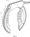
FIG. 4 , illustrated therein is thering lock 100 with certain components omitted to more clearly illustrate thecase 150. Thecase 150 provides the majority of the structural strength for thehousing 110, and may, for example, be formed of a metal material, such as steel. Thecase 150 includes anaperture 151 through which theconnector 134 extends. Theaperture 151 may, for example, have a maximum dimension d151 of one centimeter or less. Thecase 150 is generally formed of afirst part 152 including afirst flange 153 and asecond part 154 including asecond flange 155. Theflanges case 150 in its assembled state. - In certain embodiments, the
flanges flanges flanges flanges - With additional reference to
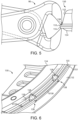
FIGS. 5 and 6 , one method of attempting to defeat thering lock 100 may involve removing theouter housing 114 to expose thecase 150, and attempting to pry thecase parts pliers 90. One or more features of thecase 150 may aid in defeating such an attack. As one example, theflanges pliers 90 from finding purchase. For example, thesecond flange 155 may have a radial depth dimension d155 of one centimeter or less. In certain forms, thefirst flange 153 may likewise have a radial depth dimension of one centimeter or less. Those skilled in the art will readily recognize that a radial depth dimension may be measured in the radial direction, or transverse to the central axis about which theshackle 120 rotates. - In certain embodiments, the
case 150 includes a plurality oframps 158 that, when engaged by thepliers 90, urge the pliers off of theflanges pliers 90 from gripping theflanges ramps 158 may be distributed about a periphery of thecase 150 such that at least one of theramps 158 engages thepliers 90 regardless of the position of thepliers 90. Theramps 158 may be offset from one another by an offset dimension d158. In certain embodiments, the offset dimension d158 may be between 1cm and 10cm, or between 1cm and 5cm. Eachramp 158 extends from asidewall 159 to an edge of thecorresponding flange pliers 90 from finding a solid grip point. - In the illustrated form, the
case 150 includes a first plurality oframps 158 formed on thefirst case portion 152 and a second plurality oframps 158 formed on thesecond case portion 154 opposite the first plurality of ramps. It is also contemplated that the first ramps and the second ramps may be staggered, and that only one of thecase portions - Certain embodiments of the present application relate to a ring lock, comprising: a case; a shackle movably mounted to the case; and a lock mechanism operable to selectively retain the shackle in a closed position; wherein the case comprises: a first case portion comprising a first flange; and a second case portion comprising a second flange; wherein each of the first flange and the second flange has a corresponding and respective radial depth dimension of one centimeter or less; and wherein the first flange and the second flange are welded to one another.
- In certain embodiments, the case further comprises at least one ramp discouraging gripping of the first flange and/or the second flange.
- In certain embodiments, the at least one ramp comprises a plurality of ramps.
- In certain embodiments, the plurality of ramps are offset from one another by an offset distance in the range of one centimeter to five centimeters.
- In certain embodiments, the at least one ramp comprises: a first ramp formed on the first flange; and a second ramp formed on the second flange.
- In certain embodiments, the first ramp and the second ramp are positioned opposite one another.
- In certain embodiments, the first ramp and the second ramp are offset from one another.
- Certain embodiments of the present application relate to a ring lock, comprising: a case; a shackle movably mounted to the case; and a lock mechanism operable to selectively retain the shackle in a closed position; wherein the case comprises: a first case portion comprising a first flange; and a second case portion comprising a second flange welded to the first flange.
- In certain embodiments, the first case portion further comprises a first plurality of ramps; wherein the second case portion further comprises a second plurality of ramps; and wherein each of the ramps is configured to discourage gripping of the corresponding case portion.
- In certain embodiments, the first plurality of ramps are aligned with the second plurality of ramps.
- In certain embodiments, the first plurality of ramps is positioned on the first flange; and wherein the second plurality of ramps is positioned on the second flange.
- In certain embodiments, each ramp of the first plurality of ramps extends from a wall adjacent the first flange to an edge of the first flange.
- In certain embodiments, the first plurality of ramps and the second plurality of ramps are offset from one another.
- In certain embodiments, each of the first flange and the second flange has a corresponding and respective radial depth dimension of one centimeter or less.
- In certain embodiments, the ring lock further comprises: an outer housing positioned about the case, the outer housing including a lip that at least partially defines a guide path; and an actuator operable to move the shackle between the closed position and an open position, the actuator comprising a knob including a channels; wherein the lip is received in the channel and limits the knob to movement along the guide path.
- Certain embodiments of the present application relate to a ring lock, comprising: a case; a shackle movably mounted to the case; and a lock mechanism operable to selectively retain the shackle in a closed position; wherein the case comprises: a first case portion comprising a first flange; and a second case portion comprising a second flange secured to the first flange; and wherein each of the first flange and the second flange has a corresponding and respective radial depth dimension of one centimeter or less.
- In certain embodiments, the first flange and the second flange are secured to one another by welding.
- In certain embodiments, the first flange includes at least one ramp; and wherein the second flange includes at least one additional ramp.
- In certain embodiments, the case further comprises an arcuate wall and a flange extending from the arcuate wall; and wherein a ramp extends outward from the wall along the flange.
- In certain embodiments, the ramp extends to an edge of the flange.
- While the invention has been illustrated and described in detail in the drawings and foregoing description, the same is to be considered as illustrative and not restrictive in character, it being understood that only the preferred embodiments have been shown and described and that all changes and modifications that come within the spirit of the inventions are desired to be protected.
- It should be understood that while the use of words such as preferable, preferably, preferred or more preferred utilized in the description above indicate that the feature so described may be more desirable, it nonetheless may not be necessary and embodiments lacking the same may be contemplated as within the scope of the invention, the scope being defined by the claims that follow. In reading the claims, it is intended that when words such as "a," "an," "at least one," or "at least one portion" are used there is no intention to limit the claim to only one item unless specifically stated to the contrary in the claim. When the language "at least a portion" and/or "a portion" is used the item can include a portion and/or the entire item unless specifically stated to the contrary.
Claims (15)
- A ring lock (100), comprising:a case (150);a shackle (120) movably mounted to the case (150); anda lock mechanism (140) operable to selectively retain the shackle (120) in a closed position;wherein the case (150) comprises:a first case portion (152) comprising a first flange (153); anda second case portion (154) comprising a second flange (155) welded to the first flange (153).
- The ring lock (100) of claim 1, wherein the first case portion (152) further comprises a first plurality of ramps (158);wherein the second case portion (154) further comprises a second plurality of ramps (158=; andwherein each of the ramps (158) is configured to discourage gripping of the corresponding case portion (152, 154).
- The ring lock (100) of claim 2, wherein the first plurality of ramps (158) are aligned with the second plurality of ramps (158).
- The ring lock (100) of claim 2 or 3, wherein the first plurality of ramps (158) is positioned on the first flange (153); and
wherein the second plurality of ramps (158) is positioned on the second flange (155). - The ring lock (100) of any one of claims 2 to 4, wherein each ramp (158) of the first plurality of ramps (158) extends from a wall (159) adjacent the first flange (153) to an edge of the first flange (153).
- The ring lock (100) of any one of claims 2 to 5, wherein the first plurality of ramps (158) and the second plurality of ramps (158) are offset from one another.
- The ring lock (100) of any one of the preceding claims, wherein each of the first flange (153) and the second flange (155) has a corresponding and respective radial depth dimension (d155) of one centimeter or less.
- The ring lock (100) of any one of the preceding claims, further comprising:an outer housing (114) positioned about the case (150), the outer housing (114) including a lip (117) that at least partially defines a guide path (116); andan actuator (130) operable to move the shackle (120) between the closed position and an open position, the actuator comprising a knob (132) including a channel (133);wherein the lip (117) is received in the channel (133) and limits the knob (132) to movement along the guide path (116).
- The ring lock (100) of claim 1, wherein at least one of the first flange (153) and the second flange (155) has a radial depth dimension (d155) of one centimeter or less,
and wherein the case (150) further comprises at least one ramp (158) discouraging gripping of the first flange (153) and/or the second flange (155). - The ring lock (100) of claim 9, wherein one of the at least one ramp (158) is offset from another of the at least one ramp (158) by an offset distance (d158) in the range of one centimeter to five centimeters.
- The ring lock (100) of claim 9 or 10, wherein the at least one ramp (158) comprises:a first ramp (158) formed on the first flange (153); anda second ramp (158) formed on the second flange (155).
- The ring lock (100) of claim 11, wherein the first ramp (158) and the second ramp (158) are positioned opposite one another.
- The ring lock (100) of claim 11, wherein the first ramp (158) and the second ramp (158) are offset from one another.
- The ring lock (100) of claim 1, wherein the case (150) further comprises an arcuate wall (159), the first and second flanges (153, 155) extending from the arcuate wall (159); and
wherein a ramp (158) extends outward from the arcuate wall (159) along at least one of the first and second flanges (153, 155). - The ring lock (100) of claim 14, wherein the ramp (158) extends to an edge of the firsr or second flange (153, 155).
Applications Claiming Priority (1)
| Application Number | Priority Date | Filing Date | Title |
|---|---|---|---|
| US17/951,609 US12146346B2 (en) | 2022-09-23 | 2022-09-23 | Attack-resistant ring lock |
Publications (2)
| Publication Number | Publication Date |
|---|---|
| EP4353574A1 true EP4353574A1 (en) | 2024-04-17 |
| EP4353574B1 EP4353574B1 (en) | 2026-04-22 |
Family
ID=88197034
Family Applications (1)
| Application Number | Title | Priority Date | Filing Date |
|---|---|---|---|
| EP23199501.0A Active EP4353574B1 (en) | 2022-09-23 | 2023-09-25 | Attack-resistant ring lock |
Country Status (2)
| Country | Link |
|---|---|
| US (2) | US12146346B2 (en) |
| EP (1) | EP4353574B1 (en) |
Citations (2)
| Publication number | Priority date | Publication date | Assignee | Title |
|---|---|---|---|---|
| NL2004606A (en) * | 2009-12-05 | 2011-06-06 | Guard B V | Horseshoe lock head. |
| EP2962920B1 (en) * | 2014-07-04 | 2021-01-13 | Allegion Netherlands B.V. | Ring lock and method for manufacturing a ring lock |
Family Cites Families (39)
| Publication number | Priority date | Publication date | Assignee | Title |
|---|---|---|---|---|
| US2647390A (en) * | 1950-03-28 | 1953-08-04 | Paulson Ernest | Bicycle lock |
| US2855028A (en) | 1955-09-06 | 1958-10-07 | Hugh B Matthews | Retractable seat belt |
| US2921353A (en) | 1956-04-04 | 1960-01-19 | Pacific Scientific Co | Quick release buckle |
| DE8121677U1 (en) | 1981-07-23 | 1981-12-03 | Sonnendorfer, Horst, 8034 Germering | DEVICE FOR ENSURING THE RETURN OF RENTED SHOPPING CART |
| US4543806A (en) | 1983-07-18 | 1985-10-01 | James J. Papandrea | Retractable cable lock |
| DE3543201C2 (en) | 1985-12-06 | 1995-01-26 | Saikousha Kasugai Kk | Ring lock |
| DK465288D0 (en) * | 1988-08-18 | 1988-08-18 | Basta Laasefab As | LOCKING DEVICE FOR LOADING A BIKE |
| NL9000430A (en) | 1990-02-22 | 1991-09-16 | Stenman Holland Nv | BIKE LOCK. |
| NL9500355A (en) | 1995-02-23 | 1996-10-01 | Stenman Holland Nv | Bicycle lock of the ring bracket type. |
| US5802889A (en) * | 1997-04-07 | 1998-09-08 | Arnold; L. Taylor | Rapid securing bicycle lock |
| DE10240570B4 (en) | 2002-08-29 | 2010-04-29 | Trelock Gmbh | frame lock |
| DE10240558B4 (en) | 2002-08-29 | 2010-04-15 | Trelock Gmbh | frame lock |
| DE10250961A1 (en) | 2002-11-01 | 2004-05-13 | ABUS August Bremicker Söhne KG | frame lock |
| DE10252080A1 (en) | 2002-11-08 | 2004-05-27 | ABUS August Bremicker Söhne KG | frame lock |
| NL1028885C2 (en) | 2005-04-27 | 2006-10-30 | Stenman Holland Nv | Bicycle lock. |
| EP1834864A1 (en) * | 2006-03-16 | 2007-09-19 | Luma Industrias, S.A. | Ring lock for bicycles with armouring parts and means for locking the latch bolt of a loop padlock |
| NL2000149C2 (en) | 2006-07-19 | 2008-01-22 | Betronic Nederland B V | Lock is portable and is for a bicycle with housing in which is one locking part and one blocking device. The blocking device blocks or releases movement from the locking part in relation to the housing for opening and closure of the lock |
| DE102010008054B4 (en) | 2010-02-16 | 2023-01-12 | ABUS August Bremicker Söhne Kommanditgesellschaft | Bicycle lock |
| DE102012102896B4 (en) | 2012-04-03 | 2023-08-10 | Trelock Gmbh | frame lock |
| US8854207B2 (en) | 2012-07-02 | 2014-10-07 | Donald S. Williams | Mobile lock with retractable cable |
| CN102979386A (en) | 2012-12-10 | 2013-03-20 | 源文兴车料(太仓)有限公司 | Horseshoe lock with double lock brackets |
| DE102013217075A1 (en) | 2013-08-27 | 2015-03-05 | ABUS August Bremicker Söhne KG | frame lock |
| DE102013217073A1 (en) | 2013-08-27 | 2015-03-05 | ABUS August Bremicker Söhne KG | frame lock |
| NL2013132B1 (en) | 2014-07-04 | 2016-08-16 | Axa Stenman Nederland B V | Ring-clip lock with detachable chain or cable. |
| US9512649B2 (en) * | 2014-09-26 | 2016-12-06 | Mohamed Mohamed | Bicycle security device |
| US9669888B1 (en) | 2015-01-16 | 2017-06-06 | Gregory Singleton | Bicycle lock and associated use thereof |
| DE102015103170A1 (en) | 2015-03-04 | 2016-09-08 | ABUS August Bremicker Söhne KG | frame lock |
| TWI537163B (en) | 2015-07-30 | 2016-06-11 | 昇詠鎖業有限公司 | A multi-functional bicycle lock structure |
| DE202015104232U1 (en) | 2015-08-11 | 2015-08-19 | Valentin Sesel | Chain lock for two-wheelers |
| DE202015104618U1 (en) | 2015-08-31 | 2015-09-22 | Sheng Yung Lock Industrial Co., Ltd. | Bicycle lock for attachment to the bicycle saddle of a bicycle |
| DE202015105949U1 (en) | 2015-11-06 | 2015-11-20 | Sheng Yung Lock Industrial Co., Ltd. | Dismountable bicycle lock with double function for alarm lighting and to protect against a bicycle theft |
| DE202016101782U1 (en) | 2016-04-05 | 2016-04-26 | Trelock Gmbh | frame lock |
| DE102018111311A1 (en) | 2018-05-11 | 2019-11-14 | ABUS August Bremicker Söhne KG | Frame lock system for a two-wheeler |
| CN108691459A (en) | 2018-07-25 | 2018-10-23 | 厦门立隽机电有限公司 | Automatically controlled two-in-one lock |
| DE102018006576A1 (en) | 2018-08-21 | 2020-02-27 | ROTEC technology GmbH | Contact sleeve, plug and charging system for electrically driven two-wheelers |
| NL2022574B1 (en) | 2019-02-14 | 2020-08-27 | Axa Stenman Nederland B V | System and method for locking a vehicle |
| US12037817B2 (en) | 2019-05-15 | 2024-07-16 | Rad Power Bikes Inc. | Bicycle security devices and system |
| BE1027178B1 (en) | 2019-08-30 | 2020-10-28 | Sentinel Nv | ELECTRONIC RING LOCK WITH REMOVABLE CHAIN LOCK |
| TWM605469U (en) | 2020-03-12 | 2020-12-21 | 胡釗豪 | Intelligent remote control and manual operation dual-purpose horseshoe lock structure |
-
2022
- 2022-09-23 US US17/951,609 patent/US12146346B2/en active Active
-
2023
- 2023-09-25 EP EP23199501.0A patent/EP4353574B1/en active Active
-
2024
- 2024-11-19 US US18/952,486 patent/US20250250823A1/en active Pending
Patent Citations (2)
| Publication number | Priority date | Publication date | Assignee | Title |
|---|---|---|---|---|
| NL2004606A (en) * | 2009-12-05 | 2011-06-06 | Guard B V | Horseshoe lock head. |
| EP2962920B1 (en) * | 2014-07-04 | 2021-01-13 | Allegion Netherlands B.V. | Ring lock and method for manufacturing a ring lock |
Also Published As
| Publication number | Publication date |
|---|---|
| EP4353574B1 (en) | 2026-04-22 |
| US12146346B2 (en) | 2024-11-19 |
| US20240102321A1 (en) | 2024-03-28 |
| US20250250823A1 (en) | 2025-08-07 |
Similar Documents
| Publication | Publication Date | Title |
|---|---|---|
| US7424813B2 (en) | Strap lock with both functions of combination code setting and key operation | |
| US8695385B2 (en) | Safe with dual locking mechanism | |
| CN1751165B (en) | Adjustable width coupler latch lock | |
| US7610784B2 (en) | Keyway cover for a lock | |
| US20170370132A1 (en) | Tailgate lock assembly | |
| US20140130555A1 (en) | Data port lock | |
| WO2010025123A1 (en) | Pin locking device | |
| US20250269921A1 (en) | Portable lock apparatus | |
| WO2000049255A1 (en) | Lock device | |
| US20230249504A1 (en) | Security Lock and Cover for Trailer Jacks | |
| WO2012112633A1 (en) | Portable lockable enclosure | |
| EP4353574B1 (en) | Attack-resistant ring lock | |
| US11377876B2 (en) | Magnetic keeper for bicycle lock element | |
| US20040083776A1 (en) | Kingpin locking device | |
| US6510718B1 (en) | Anti-theft device for steering wheel | |
| US12624569B2 (en) | Locking enclosure | |
| US7469920B2 (en) | Kingpin lock | |
| CN215435671U (en) | Anti-disassembling seal structure | |
| US20090183540A1 (en) | Pickup-truck tailboard lock | |
| CN116537645A (en) | Latch lock | |
| JP2001152711A (en) | Door lock handle device | |
| JP4733451B2 (en) | Ignition switch device | |
| US5673577A (en) | Automobile anti-theft device | |
| CN113232430A (en) | Anti-disassembling seal structure | |
| GB2589598A (en) | Steering wheel lock |
Legal Events
| Date | Code | Title | Description |
|---|---|---|---|
| PUAI | Public reference made under article 153(3) epc to a published international application that has entered the european phase |
Free format text: ORIGINAL CODE: 0009012 |
|
| STAA | Information on the status of an ep patent application or granted ep patent |
Free format text: STATUS: THE APPLICATION HAS BEEN PUBLISHED |
|
| AK | Designated contracting states |
Kind code of ref document: A1 Designated state(s): AL AT BE BG CH CY CZ DE DK EE ES FI FR GB GR HR HU IE IS IT LI LT LU LV MC ME MK MT NL NO PL PT RO RS SE SI SK SM TR |
|
| STAA | Information on the status of an ep patent application or granted ep patent |
Free format text: STATUS: REQUEST FOR EXAMINATION WAS MADE |
|
| 17P | Request for examination filed |
Effective date: 20241017 |
|
| RBV | Designated contracting states (corrected) |
Designated state(s): AL AT BE BG CH CY CZ DE DK EE ES FI FR GB GR HR HU IE IS IT LI LT LU LV MC ME MK MT NL NO PL PT RO RS SE SI SK SM TR |
|
| STAA | Information on the status of an ep patent application or granted ep patent |
Free format text: STATUS: EXAMINATION IS IN PROGRESS |
|
| 17Q | First examination report despatched |
Effective date: 20250319 |
|
| GRAP | Despatch of communication of intention to grant a patent |
Free format text: ORIGINAL CODE: EPIDOSNIGR1 |
|
| STAA | Information on the status of an ep patent application or granted ep patent |
Free format text: STATUS: GRANT OF PATENT IS INTENDED |
|
| INTG | Intention to grant announced |
Effective date: 20251114 |
|
| GRAS | Grant fee paid |
Free format text: ORIGINAL CODE: EPIDOSNIGR3 |
|
| GRAA | (expected) grant |
Free format text: ORIGINAL CODE: 0009210 |
|
| STAA | Information on the status of an ep patent application or granted ep patent |
Free format text: STATUS: THE PATENT HAS BEEN GRANTED |
|
| AK | Designated contracting states |
Kind code of ref document: B1 Designated state(s): AL AT BE BG CH CY CZ DE DK EE ES FI FR GB GR HR HU IE IS IT LI LT LU LV MC ME MK MT NL NO PL PT RO RS SE SI SK SM TR |
|
| REG | Reference to a national code |
Ref country code: CH Ref legal event code: F10 Free format text: ST27 STATUS EVENT CODE: U-0-0-F10-F00 (AS PROVIDED BY THE NATIONAL OFFICE) Effective date: 20260422 Ref country code: GB Ref legal event code: FG4D |
|
| REG | Reference to a national code |
Ref country code: DE Ref legal event code: R096 Ref document number: 602023015631 Country of ref document: DE |