EP4353565A1 - Mehrzweckträger und verfahren zur neukonfiguration eines mehrzweckträgers - Google Patents
Mehrzweckträger und verfahren zur neukonfiguration eines mehrzweckträgers Download PDFInfo
- Publication number
- EP4353565A1 EP4353565A1 EP22201344.3A EP22201344A EP4353565A1 EP 4353565 A1 EP4353565 A1 EP 4353565A1 EP 22201344 A EP22201344 A EP 22201344A EP 4353565 A1 EP4353565 A1 EP 4353565A1
- Authority
- EP
- European Patent Office
- Prior art keywords
- wheel assembly
- orientation
- wheel
- carrier
- rotation axis
- Prior art date
- Legal status (The legal status is an assumption and is not a legal conclusion. Google has not performed a legal analysis and makes no representation as to the accuracy of the status listed.)
- Granted
Links
Images


Classifications
-
- B—PERFORMING OPERATIONS; TRANSPORTING
- B62—LAND VEHICLES FOR TRAVELLING OTHERWISE THAN ON RAILS
- B62B—HAND-PROPELLED VEHICLES, e.g. HAND CARTS OR PERAMBULATORS; SLEDGES
- B62B3/00—Hand carts having more than one axis carrying transport wheels; Steering devices therefor; Equipment therefor
- B62B3/02—Hand carts having more than one axis carrying transport wheels; Steering devices therefor; Equipment therefor involving parts being adjustable, collapsible, attachable, detachable or convertible
-
- B—PERFORMING OPERATIONS; TRANSPORTING
- B62—LAND VEHICLES FOR TRAVELLING OTHERWISE THAN ON RAILS
- B62B—HAND-PROPELLED VEHICLES, e.g. HAND CARTS OR PERAMBULATORS; SLEDGES
- B62B7/00—Carriages for children; Perambulators, e.g. dolls' perambulators
- B62B7/04—Carriages for children; Perambulators, e.g. dolls' perambulators having more than one wheel axis; Steering devices therefor
- B62B7/044—Carriages for children; Perambulators, e.g. dolls' perambulators having more than one wheel axis; Steering devices therefor three wheeled
- B62B7/046—Carriages for children; Perambulators, e.g. dolls' perambulators having more than one wheel axis; Steering devices therefor three wheeled with interchangeable front wheel unit
-
- B—PERFORMING OPERATIONS; TRANSPORTING
- B62—LAND VEHICLES FOR TRAVELLING OTHERWISE THAN ON RAILS
- B62B—HAND-PROPELLED VEHICLES, e.g. HAND CARTS OR PERAMBULATORS; SLEDGES
- B62B2301/00—Wheel arrangements; Steering; Stability; Wheel suspension
- B62B2301/05—Details of the attachment of the wheel assembly to the chassis
-
- B—PERFORMING OPERATIONS; TRANSPORTING
- B62—LAND VEHICLES FOR TRAVELLING OTHERWISE THAN ON RAILS
- B62B—HAND-PROPELLED VEHICLES, e.g. HAND CARTS OR PERAMBULATORS; SLEDGES
- B62B2301/00—Wheel arrangements; Steering; Stability; Wheel suspension
- B62B2301/14—Wheel arrangements; Steering; Stability; Wheel suspension the wheel arrangement pivoting around a horizontal-longitudinal axis
Definitions
- the present disclosure relates to carriers which can be reconfigured for transporting one or more individuals, for transporting pets and/or for transporting cargo and for transporting by means of pushing, pulling or by towing for instance by a bicycle. More specifically, the present invention relates to a multipurpose carrier configured for transporting one or more passengers and/or cargo and to a method for reconfiguring a multipurpose carrier.
- Multipurpose carriers such as a reconfigurable bike trailer that can also be configured for use as a stroller and/or for towing when skiing etc., are becoming more increasingly more common items to facilitate a healthy, comfortable and environmentally friendly lifestyle.
- Such carriers can serve a multitude of purposes, allowing transportation of children, pets and miscellaneous cargo during the daily commute and/or for recreation.
- Multipurpose carriers are often collapsible, for instance for facilitating storing or for transportation of the carrier.
- Carriers are thus commonly provided with a chassis that is foldable, the chassis typically being a metal frame construction to which a textile and/or plastic cover is attached for forming seat bases and/or a passenger cabin.
- the chassis typically being a metal frame construction to which a textile and/or plastic cover is attached for forming seat bases and/or a passenger cabin.
- one or several wheels of the carrier are usually removable not only for reducing the size of the carrier during storage but also as it may be required for a certain configuration of the carrier. For instance, when towing by bike it is under most circumstances required to remove the front wheel(s) of the carrier.
- an object of the present invention is to provide an improved multipurpose carrier which alleviates at least one of the drawbacks of the prior art.
- an object of the present invention is to provide a multipurpose carrier where reconfiguration is facilitated between the different purposes of the multipurpose carrier.
- a multipurpose carrier having improved reliability and durability.
- a multipurpose carrier configured for transporting one or more passengers and/or cargo by pushing or pulling the carrier, the carrier comprising:
- the first orientation and the second orientation of the wheel assembly may be separated angularly by between 30° and 120°, preferably approximately 90°.
- the first and second orientation may be separated with an angle outside of the aforementioned interval as well, however having a larger angular separation reduces the risk of improper arrangement of the wheel assembly in the first orientation.
- a small angular separation could generate a risk of a user arranging the wheel assembly incorrectly near the second orientation under the belief that it is in the first orientation such that it later unintentionally becomes detached from the carrier.
- the third orientation of the wheel assembly may be angularly separated from the first position by approximately 180°.
- the wheel of the wheel assembly will thus be arranged in a stowed position and such that the risk of it ending up being in the way during use of the carrier is minimized.
- the wheel assembly may be configured to be rotated from the first position to the second position and/or to the third position with the wheel of the wheel assembly moving along an arc only in an upwardly vertical direction. Accordingly, no part of the carrier needs to raised from the ground for changing the orientation of the wheel assembly. This is particularly beneficial when the carrier is used as a bike trailer as the carrier can be connected to the bike while being reconfigured such that the wheel assembly is reoriented for instance from the first orientation to the third orientation or vice versa. The need for the user to support the carrier during this process is also reduced.
- the wheel assembly may comprise a tensioning element, the tensioning element being configured to provide a pretensioning force between the base and a corresponding wheel assembly attachment on the multipurpose carrier in a direction pressing the base against the wheel assembly attachment.
- the tensioning element may further support the wheel assembly as it is being rotated around the wheel assembly rotation axis. The tensioning element facilitates locking and unlocking the wheel assembly for reorientation thereof.
- the wheel assembly may comprise a securing member configured to be moveable through a corresponding first opening in a wheel assembly attachment on the multipurpose carrier in at least the second orientation of the wheel assembly, and wherein the securing member in at least the first orientation of the wheel assembly is configured to be engageable against an abutment surface on the multipurpose carrier.
- the securing member may be arranged on the tensioning element, thus rotating therewith during reorientation of the wheel assembly.
- the abutment surface may be arranged on a resilient member being configured to be resiliently deformed by the engagement of the securing member upon provision of the pre-tensioning force by the tensioning element.
- the pretensioning force for attaching the wheel assembly and securing the wheel assembly in at least the first orientation and the second orientation may thus be controlled, in order to provide a secure attachment while avoiding unnecessarily high material stresses. The durability of the carrier is thus improved.
- the first opening may be arranged in the resilient member and a second opening be provided in the wheel assembly attachment through which the first opening is accessible.
- the securing member may be moveable through the second opening in any orientation of the wheel assembly around the wheel assembly rotation axis, thus facilitating securing that the wheel assembly is attached to the resilient member and not incorrectly against any other surface in the second opening.
- the second opening being arranged exteriorly of the first opening.
- the wheel of the wheel assembly may be arranged in a castor configuration such that the wheel can rotate around a second wheel rotation axis in relation to the base.
- the multipurpose carrier may further comprise a rotation locking mechanism, the rotation locking mechanism comprising a locking member engageable in a corresponding first locking recess such that rotation of the wheel around the second wheel rotation axis is prevented, wherein the locking member is configured to be automatically engaged in the first locking recess at least when the wheel assembly is in a third orientation being angularly separated from the first position by approximately 180° and automatically disengaged from the first locking recess at least when the wheel assembly is in the first orientation. Accordingly, the wheel will be automatically locked and unlocked for rotation around the second wheel rotation axis by reorienting the wheel assembly. The wheel not rotating around the second wheel rotation axis while the wheel assembly is in the third orientation, i.e. stowed, reduces the risk of the wheel ending up in the way and obstructing the use of the carrier.
- the locking member may be configured to be automatically engaged in and disengaged from the first locking recess by the force of gravity.
- the locking member may comprise a plurality of friction reducing elements and/or wherein the locking member is manufactured from a material having a material density of between 3 g/cm 3 and 15 g/cm 3 , preferably between 6 g/cm 3 and 8 g/cm 3 , thus improving the automatic locking functionality of the rotation locking mechanism.
- the locking member being provided with friction reducing elements reduces the risk of detrimental effect from for instance dirt, which could for instance cause the locking member to become stuck.
- a second aspect is a method for reconfiguring a multipurpose carrier of the first aspect provided, the method comprising:
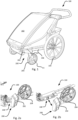
- FIGS 1, 2a and 2b discloses a perspective view of a multipurpose carrier 100 with a wheel assembly 200 in first orientation and in a second orientation respectively.
- a carrier 100 according to teachings herein is to be interpreted for instance as a bike trailer that can be towed by a bicycle and which can be converted for use as a stroller and/or for towing by a person wearing a harness.
- the multipurpose carrier 100 allows reconfiguration of at least one of the wheels 104, 204 of the carrier 100.
- at least one of the wheels 104, 204 of the carrier 100 may be removable from the carrier 100 as may be required for instance when using the carrier 100 as a bike trailer.
- all of the wheels 104, 204 of the carrier 100 can be removed from the carrier 100.
- the carrier 100 is illustrated as a four wheeled carrier 100 having two front wheels 204 and two rear wheels 104, the rear wheels 104 being larger than the front wheels 204. It is however to be realized that the teachings here could also be applied to three wheeled carriers, for instance being provided with only one front wheel.
- the multipurpose carrier 100 may as is shown in comprise a chassis 106, the chassis 106 forming the load bearing structure of the carrier 100.
- the chassis 106 may be manufactured from a metal material such as aluminum and/or a plastic material and allow collapsing of the carrier 100 into a folded and less space consuming state.
- the carrier 100 may further be provided with a cover 102 forming a cabin for holding one or more passengers and/or cargo/pets etc.
- the cover 102 may be formed from one or more portions of textile and/or plastic material and may be removably attached to the chassis 106.
- At least one wheel 204 of the multipurpose carrier 100 forms part of a wheel assembly 200.
- the wheel assembly 200 is to be interpreted as a separate unit that is removably connectable by reorientation in relation to the multipurpose carrier 100.
- the multipurpose carrier 100 may in a preferred embodiment comprise two wheel assemblies 200 forming the front wheel pair of a four wheeled multipurpose carrier 100.
- Each wheel assembly comprises a base 202 in relation to which the wheel 204 of the wheel assembly 200 can rotate around at least a first wheel rotation axis A1.
- the first wheel rotation axis A1 of each wheel assembly 200 forming the axis around which the associated wheel 204 rotates when the multipurpose carrier 100 is under movement, i.e. it is the center axis of the wheel 204.
- Each wheel assembly 200 is configured to be arranged in relation to the multipurpose carrier 100 in at least a first orientation in relation to a wheel assembly rotation axis A3 in which the wheel 204 of the wheel assembly 200 is arranged in a use state as illustrated in Figure 1 .
- Use state is to be interpreted as oriented with the wheel 204 of the multipurpose carrier 100 arranged such that it is configured to carry at least a part of the load of the carrier 100.
- the wheel assembly rotation axis A3 is the axis around which the wheel assembly can be reoriented for reconfiguration of the multipurpose carrier 100 for suiting the different purposes thereof.
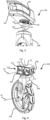
- each wheel assembly 200 may be configured to be oriented in a second orientation in relation to the wheel assembly rotation axis A3.
- the wheel assembly 200 in the second orientation thereof can be released and connected from/to the multipurpose carrier 100, as is illustrated in Figure 2b .
- the first orientation shown in Figure 1 , being separated from the second orientation by a second orientation angular separation of the wheel assembly 200 around the wheel assembly rotation axis A3.
- the second orientation may be separated from the first orientation by between 30° and 120°, preferably approximately 90°.
- the wheel assembly 200 can be removed and attached to the multipurpose carrier 100.
- each wheel assembly 200 may be configured to arranged in a third orientation around the wheel assembly rotation axis A3.
- the third orientation being separated from the first orientation by a third orientation angular separation of the wheel assembly 200 around the wheel assembly rotation axis A3.
- the wheel assembly 200 is arranged in a stowed state.
- a stowed state is to interpreted as an orientation of the wheel assembly 200 in which the wheel 204 thereof is not configured to carry a load of the multipurpose carrier 100.
- the third orientation may be separated angularly by approximately 180° from the first orientation.
- the wheel assembly 200 is configured to be secured in the third orientation such that the orientation of the wheel assembly 200 cannot be unintentionally altered.
- the wheel assembly 200 may further be configured to be arranged in a first orientation, a second orientation as defined herein and in a third orientation as defined herein.
- the second orientation is defined as an orientation in which the wheel assembly can be released from the multipurpose carrier 100.
- more than one second orientation may be provided in a 360° rotation of the wheel assembly 200 around the wheel assembly rotation axis A3.
- the third orientation is defined as an orientation in which the wheel assembly 200 is stowed.
- more than one third orientation may be provided in a 360° rotation of the wheel assembly 200 around the wheel assembly rotation axis A3.
- each second orientation angular separation from the first orientation around the wheel assembly rotation axis A3 is different from each third orientation angular separation from the first orientation around the wheel assembly rotation axis A3.
- the wheel assembly 200 may be configured to be attached to a wheel assembly attachment 108 formed on the carrier 100.
- the wheel assembly attachment 108 may be formed as an integral part of the chassis 106 and/or as a separate part connected thereto such that it allows transmission of the weight of the carrier 100 via the wheel assembly attachment 108 to the wheel assembly 200.
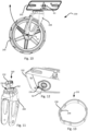
- FIG. 4 discloses a perspective view of a wheel assembly 200.
- each wheel assembly comprises a base 202.
- the base 202 forms the portion of the wheel assembly 100 that is configured for connection to the multipurpose carrier 100.
- the base 202 may be formed from a plastic and/or metallic material as realized by a person skilled in the art.
- the wheel 204 of the wheel assembly 200 may be connected to the base 202 in a castor configuration, the wheel assembly 200 further comprising a wheel fork 208 to which the wheel 204 is mounted.
- the wheel fork 208 preferably being rotatably mounted to the base 202 such that the wheel fork 208 and the associated wheel 204 can rotate around a second wheel rotation axis A2 in relation to the base 202.
- Figure 5 shows an exploded view of a wheel assembly 200, where it is illustrated how the wheel fork 208 may be connected to the base 202.
- a shaft 216 may be provided which is connected to the wheel fork 208 and further connected to a bearing 218 arranged in a corresponding opening 220 in the base 202.
- the bearing 218 provides reduced friction as the wheel fork 208 is rotated around the second wheel rotation axis A2 in relation to the base 202.
- the bearing may be a radial ball bearing or another type of bearing suitable for the purpose, as realized by a person skilled in the art.
- the shaft 216 may be rotationally fixed in relation to the wheel fork 208, such that the rotation is provided by the bearing 218 in the base 202.
- a bearing may also be provided between the shaft 216 and the wheel fork 208 thus providing relative rotation also between the shaft 216 and the wheel fork 208.
- the bearing 218 is provided in the wheel fork 208 while the shaft 216 is arranged rotationally fixed in relation to the base 202. As the entire wheel assembly 200 can be reoriented in relation to the multipurpose carrier 100 and/or removed therefrom, it is under normal use not necessary to remove the wheel fork 208 from the base 202. The bearing 218 and the shaft 216 will thus be subjected less to the surroundings and thus less to dirt or debris, which reduces the wear of the bearing 218 and improves durability.
- Figure 6 shows a perspective view of a wheel assembly 200.
- the wheel assembly 200 may comprise a tensioning element 210 which may be connected to a lever 206.
- the lever 206 being configured to achieve axial movement of the tensioning element 210.
- the tensioning element 210 may in addition to the foregoing be considered a reorientation locking mechanism 210, locking the wheel assembly in each orientation and unlocking the wheel assembly 200 such the orientation thereof can be changed.
- the axial extension of the tensioning element 210 defines the wheel assembly rotation axis A3, as the wheel assembly 200 may be configured to rotate around the tensioning element 210. Further, the tensioning element 210 is configured to be reciprocally moveable axially along the wheel assembly rotation axis A3 by means of a corresponding movement of the lever 206. The tensioning element 210 is configured to provide a pretensioning force between the base 202 and the wheel assembly attachment 108 on the multipurpose carrier 100 in a direction pressing the base 202 against the wheel assembly attachment 108. The tensioning element 210 thus has a retracted state and an extended state, as will be elaborated further on below.
- the base 202 may be provided with at least one protrusion 214 being arranged protruding towards the multipurpose carrier 100.
- Each protrusion 214 is configured to cooperate and engage with a corresponding recess 110 in the wheel assembly attachment 108 (shown in Figure 7a ), thus forming a locking effect for preventing relative rotation between the base 202 and the wheel assembly attachment 108 when the tensioning element 210 is in the retracted state.
- each protrusion 214 and each recess 110 reduces the strain on the tensioning element 210 as any rotational force exerted on the wheel assembly 200 will be taken up or at least reduced by the protrusion 214 and the corresponding recess 110.
- the wheel assembly 200 may comprise a securing member 212.
- the securing member 212 is preferably arranged on the tensioning element 210 and protruding therefrom.
- the securing member 212 may in a preferred embodiment be arranged such that it is rotationally fixed in relation to the base 202, thus rotating therewith as the wheel assembly 200 is reoriented from the first to the second and/or third orientation or vice versa.
- the securing member 212 may as is shown be arranged and configured such that it protrudes outside of the circumference of the adjacent peripheral surface of the tensioning element 210, the securing member 212 being configured to be arranged in engagement against an abutment surface 116 whereby the tensioning element 210 provides the pretensioning force in at least the first orientation and optionally in the third orientation of the wheel assembly 200.
- the securing member 212 is shown being essentially rectangular in shape, it is however to be realized that the securing member 212 may be provided with other shapes as well.
- the securing member 212 is configured to be moveable through a corresponding first opening 114 (shown in Figure 7a ) in the wheel assembly attachment 108 on the multipurpose carrier 100 in at least the second orientation of the wheel assembly 200.
- the first opening 114 corresponding to the securing member 212 is to be interpreted as that the first opening 114 and the securing member 212 are mutually formed such that the wheel assembly 200 can be secured in the first orientation thereof and released in the second orientation and/or secured in the third orientation of the wheel assembly 200. Accordingly, a plurality of shapes of the first opening 114 as well as of the securing member 212 is possible within the scope of this disclosure.
- the securing member 212 is in at least the first orientation of the wheel assembly 200 configured to be engageable against an abutment surface 116, shown in Figure 7b , on the multipurpose carrier.
- the abutment surface 116 is arranged facing away from the base 202 of the wheel assembly 200 and is preferably arranged interiorly of the wheel assembly attachment 108.
- the abutment surface 116 may be arranged on a resilient member 112.
- the resilient member 112 may be formed by a spring element such as a blade spring.
- the resilient member 112 is isolated from the wheel assembly attachment 108 for illustrating the function thereof and the engagement of the securing member 212. It is also conceivable that the resilient member is formed from an elastic plastic and/or polymeric material. The resilient member 112 will, by resiliently deforming when exerted to the securing member 212 engagement, provide reliable pretensioning force while reducing the risk that any undesired material strain forms due to the contact between the securing member 212 and the abutment surface 116.
- the resilient member 112 is configured to be resiliently deformed by the engagement of the securing member 212 upon provision of the pre-tensioning force by the tensioning element 210.
- the resilient member 112 may further be integrally formed with the wheel assembly attachment 108 or, as illustrated in Figures 7a and 7b , be formed separately.
- first opening 114 may be arranged in the resilient member 112, the first opening 114 being configured to receive the tensioning element 210 comprising the securing member 212.
- a second opening 120 may be provided in the wheel assembly attachment 108 through which the first opening 114 is accessible.
- the resilient member 112 is omitted for clarity.
- the securing member 212 may be moveable through the second opening 120 in any orientation around the wheel assembly rotation axis A3 of the wheel assembly 200.
- the second opening 120 may be formed in the wheel assembly attachment 108, as an integral part thereof.
- the wheel assembly attachment 108 may be formed from a plastic and/or metallic material.
- the second opening 120 being configured to allow passage of the securing member 212 in any orientation of the wheel assembly 200 around the wheel assembly rotation axis A3 facilitates attachment of the wheel assembly 200 to the multipurpose carrier 100.
- the risk of incorrect attachment of the wheel assembly 200 to the multipurpose carrier 100 is reduced, for instance in an orientation where the securing member 212 is not in contact with the abutment surface 116 on the resilient member 114 but instead abuts directly against the wheel assembly attachment 108.
- the wheel assembly attachment 108 may comprise a bottom cavity 122 arranged behind the resilient member 112.
- the cavity 122 is configured to allow rotation of the securing member 122 therein.
- the tensioning element 210 may be provided with a support 242.
- the support 242 is preferably arranged protruding coaxially with the wheel assembly rotation axis A3 on the side of the tensioning element 210 intended to be facing towards the wheel assembly attachment 108.
- the support 242 is configured to cooperate with a support recess 124, shown in Figure 7c , such that rotation of the wheel assembly 200 around the wheel assembly rotation axis A3 is facilitated. This aids the user in the reorientation of the wheel assembly 200.
- the securing member 212 can only be rotated in relation to the wheel assembly attachment 108 when the support 242 is arranged in the support recess 124.
- the securing member 212 cannot be moved entirely through the first opening 114 in the resilient member 112 and will thus make contact with the first opening 114 upon rotation of the wheel assembly 200. Moreover, contact between the resilient member 112 abutment surface 116 and the securing member 212 may prevent removal of the support 242 from the support recess 124 when the wheel assembly 200 is not arranged in the second orientation.
- the support 242 and the support recess 124 along with the securing member 212 and the resilient member 112 guides the rotation of the wheel assembly 200 around the wheel assembly rotation axis A3 and keeps the wheel assembly 200 correctly aligned with wheel assembly attachment 108 as it is being rotated between the first and third orientation of the wheel assembly 200.
- the securing member 212 rotates unrestricted in the bottom cavity 122 of the wheel assembly attachment 108 preferably without making contact with the walls along the periphery of the bottom cavity 122.
- Figures 8 and 9 show a top view of the wheel assembly 200.
- the wheel assembly 200 is shown with the tensioning element 210 in the retracted state as controlled by the lever 206.
- the lever 206 is pivotable around a lever rotation axis A4 for setting the tensioning element 210 in the retracted state or in the extended state as illustrated in Figure 9 .
- the lever 206 is pivotably connected to the tensioning element 210 in the lever rotation axis A4.
- the lever 206 comprises a first contact surface 224, the perpendicular distance therefrom to the lever rotation axis A4 defining the retracted state of the tensioning element 210.
- the first contact surface 224 is arranged in contact with a lever abutment surface 228 on the base 202 when the tensioning element 210 is in the retracted state.
- the lever 206 comprises a second contact surface 226 angularly offset from the first contact surface 224 around the lever rotation axis A4, the perpendicular distance from the second contact surface 226 to the lever rotation axis A4 defining the extended state of the tensioning element 210 and is thus shorter than the corresponding distance between the first contact surface 224 and the lever rotation axis A4.
- the second contact surface 226 is arranged in contact with the lever abutment surface 228 on the base 202 when the tensioning element 210 is in the retracted state.
- a biasing member 230 may be provided between the tensioning element 210 and the base 202.
- the biasing member 230 which may be formed by a coil spring or another element of similar function, is configured to bias the tensioning element 210 towards the extended position.
- the biasing member 230 thus facilitates keeping the lever 206 in contact with the lever abutment surface 228 during the movement of the lever 206, thus facilitating controlling the movement of the lever 206.
- the biasing member 230 facilitates attachment and release of the wheel assembly 200 to/from the multipurpose carrier 100 as it keeps the tensioning element 210 in the extended state without user interaction when the lever 206 is the corresponding position with the second contact surface 226 in contact with the lever abutment surface 228.
- Figure 10 shows a side view of a wheel assembly 200 from the side intended to face the multipurpose carrier 200. It is illustrated how by rotation around the wheel assembly rotation axis A3, the wheel assembly 200 is configured to be rotated from the first orientation illustrated in Figure 10 to the second orientation as shown in Figure 2 and/or to the third orientation as shown in Figure 3 with the wheel 204 of the wheel assembly 200 moving along an arc, illustrated by the arrow in Figure 10 , only in an upwardly vertical direction. As such, the wheel assembly 200 can be brought from the first orientation to the second and/or third orientation and vice versa without having to lift the multipurpose carrier 100.
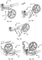
- Figure 11 shows a perspective view of the wheel fork 208 of the wheel assembly 200
- Figure 12 shows a detail bottom view of the base 202 of the wheel assembly 200
- Figure 13 shows a perspective view of a locking member 232.
- the wheel assembly 200 may be provided with a rotation locking mechanism 240.
- the rotation locking mechanism 240 is configured to prevent relative rotation between the wheel 204, more particularly between the wheel fork 208, and the base 202 around the second wheel rotation axis A2 at least when the wheel assembly 200 is in the third orientation which is angularly separated from the first orientation by approximately 180°.
- the rotation of the wheel 204 and/or the wheel fork 208 around the second wheel rotation axis A2 may be automatically locked when the wheel assembly 200 is in or near the third position. This facilitates placing the wheel assembly 200 in the stowed position and reduces the risk of the wheel 204 protruding outside of the periphery of the carrier 100.
- the rotation locking mechanism 240 is further configured to be automatically disengaged when the wheel assembly 200 is arranged at least in the first orientation, thus allowing turning and rotation of the wheel 204 and the wheel fork 208 around the second wheel rotation axis A2.
- the rotation locking mechanism 240 may comprise a locking member 232 engageable in a corresponding first locking recess 236 such that rotation of the wheel 204 and/or the wheel fork 208 around the second wheel rotation axis A2 is prevented.
- the locking member 232 is configured to be automatically engaged in the first locking recess 236 at least when the wheel assembly is in the third orientation and automatically disengaged from the first locking recess 236 at least when the wheel assembly 200 is in the first orientation.
- the locking member 232 may as is illustrated be formed extending around the second wheel rotation axis A2.
- the locking member 232 is provided with a shape and/or arrangement thereof which by cooperation with the first locking recess 236 prevents rotation of the wheel fork 208.
- the locking member 232 and the corresponding first locking recess 236 may be circular but arranged radially offset in relation to the second wheel rotation axis A2.
- the locking member 232 and the corresponding first locking recess 236 may be provided with a non-circular shape as illustrated in Figures 11 to 13 such that the locking member 232 only can be arranged in the first locking recess 236 in one relative orientation of the wheel 204 / wheel fork 208 and the base 202.
- the locking member 232 is configured to rotate with the wheel 204 and/or with the wheel fork 208 around the second wheel rotation axis A2.
- the locking member 232 may as is illustrated in Figure 11 be arranged in a second locking recess 234, the second locking recess 234 being arranged in the wheel fork 208.
- the second locking recess 234 is configured to accommodate the locking member 232 such that it does not engage with the first locking recess 236 when the wheel assembly 200 is at least in the first orientation.
- the second locking recess 234 may be configured to have a depth essentially corresponding to or be larger than the height of the locking member 232 such that the locking member 232 does not protrude outside of the second locking recess 234 when fully inserted therein.
- the first locking recess 236 is configured to partially accommodate the locking member 232 such that the locking member 232 is configured to be arrangeable in simultaneous engagement with both the first locking recess 236 and the second locking recess 234 at least when the wheel assembly 200 is in the third orientation.
- the depth of the first locking recess 236 is less than the height of the locking member 232 as measured along the second wheel rotation axis A2. Accordingly, the locking member 232 will not be moved out of engagement from the second locking recess 234 even if the locking member 232 is fully inserted into the first locking recess 236.
- the locking member 232 is configured to be automatically engaged in and disengaged from the first locking recess 236 by the force of gravity.
- the locking member 232 thus moving out of the second locking recess 234 when the force of gravity overcomes the friction force between the locking member 232 and the second locking recess 234.
- the locking member 232 is moved into the first locking recess 236 when the relative orientation around the second wheel rotation axis A2 of the wheel 204 and/or the wheel fork 208 and the base 202 is such that the first and second locking recesses 236, 234 are aligned.
- the locking member 232 may be provided with a plurality of friction reducing elements 238.
- the friction reducing elements 238 may be distributed around the interior and/or exterior periphery of the locking member 232.
- Each friction reducing element 238 is formed by a protrusion preferably having an extension in the insertion direction of the locking member 232 into each of the first and second locking recess 236, 234.
- the friction reducing elements 238 reduces the contact surface between the locking member 232 and the first and second locking recesses 236, 234 respectively, thus reducing the retaining force due to friction between locking member 232 and the base 202.
- the friction reducing elements 238 further reduces the risk of dirt becoming wedged between the locking member 232 and the first and second locking recesses 236, 234 respectively.
- the locking member 232 may be manufactured from a material having a material density of between 3 g/cm 3 and 15 g/cm 3 , preferably between 6 g/cm 3 and 8 g/cm 3 .
- the locking member 232 may be manufactured from a metallic material such as zinc. Other materials are naturally also considered, such as plastic and/or composite materials.
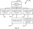
- FIGS 14a to 14e along with Figure 15 illustrate a method 1000 for reconfiguring a multipurpose carrier 100 according to the teachings herein.
- the method 1000 comprises adjusting 1002 a wheel assembly locking mechanism 210, such as the tensioning element 210 of the wheel assembly 200, arranging 1004 the wheel assembly 200 in a first orientation in relation to a wheel assembly rotation axis A3 corresponding to a use state, arranging 1006 the wheel assembly 200 in a second orientation corresponding to a releasable state of the wheel assembly 200 from the multipurpose carrier 100 and/or arranging 1008 the wheel assembly 200 in a third orientation corresponding to a stowed state of the wheel assembly 200.
- the first orientation being separated from the second orientation and the third orientation by an angular separation of the wheel assembly around the wheel assembly rotation axis A3.
- the first orientation of the wheel assembly 200 is illustrated in Figure 14a and is the orientation of the wheel assembly 200 which is the use state of the carrier 100, i.e. when the carrier 100 is to be used for carrying a load at least partially supported by means of the wheel assembly 200.
- the second orientation in which the wheel assembly 200 is releasable from the multipurpose carrier 100 is illustrated in Figure 14b in which the wheel assembly 200 is rotated around the wheel assembly rotation axis A3 between 30° and 120°, preferably approximately 90° from the first orientation. It is to realized that the second orientation may per definition also be arranged rotated approximately 180° from the orientation illustrated in Figure 14b , i.e. such that the wheel 204 is arranged forwardly of the base 202. In other words, more that one second orientation may be provided. As is illustrated in Figure 14c , the arranging 1006 of the wheel assembly 200 in the second orientation may further comprise releasing/connecting 1006a the wheel assembly 200 from the carrier 100. When arranged in the second orientation, the wheel assembly 200 is releasable/connectable to the carrier 100 by a lateral movement as illustrated in Figure 14c .
- Figure 14d illustrates the wheel assembly being arranged 1008 in the third orientation, the third orientation of the wheel assembly 200 being angularly separated from the first position by approximately 180°. In the third orientation, the wheel assembly 200 is in a stowed position as described in the foregoing.
- Arranging 1008 the wheel assembly in the third orientation may further comprise locking 1008a the wheel 204 from rotation around a second wheel rotation axis A2 as is illustrated in Figures 14d and 14e .
- Locking 1008a the wheel 204 from rotation may comprise arranging the wheel 204 in a predetermined orientation around the second wheel rotation axis A2 such that a rotation locking mechanism 240 is engaged, as outlined in the foregoing in conjunction with the description of Figures 11 to 13 , and thus prevents further rotation of the wheel 204 and/or the wheel fork 208 around the second wheel rotation axis A2.
- the rotation locking mechanism 240 may be configured to disengage automatically once the wheel assembly 200 is oriented near or in the first orientation thus allowing rotation of the wheel 204 / wheel fork 208 around the second wheel rotation axis A2.
- the adjusting 1002 of the reorientation locking mechanism 210 of the wheel assembly 200 may be performed before/during/after each change of orientation as described in relation to Figures 8 and 9 in the foregoing. More particularly, the adjusting 1008 the reorientation locking mechanism 210 may comprise setting the tensioning element 210 in an extracted state before changing from the first orientation to the second and/or third orientation of the wheel assembly 200 and from the third orientation to the second and/or first orientation of the wheel assembly 200. The adjusting 1008 the reorientation locking mechanism 210 may further comprise setting the tensioning element 210 in a retracted state when the wheel assembly 200 has reached either of the first and third orientation thus preventing the wheel assembly 200 from unintentionally changing its orientation around the wheel assembly rotation axis A3.
Landscapes
- Engineering & Computer Science (AREA)
- Chemical & Material Sciences (AREA)
- Combustion & Propulsion (AREA)
- Transportation (AREA)
- Mechanical Engineering (AREA)
- Handcart (AREA)
Priority Applications (4)
| Application Number | Priority Date | Filing Date | Title |
|---|---|---|---|
| EP22201344.3A EP4353565B1 (de) | 2022-10-13 | 2022-10-13 | Mehrzweckträger und verfahren zur neukonfiguration eines mehrzweckträgers |
| PCT/EP2023/075379 WO2024078816A1 (en) | 2022-10-13 | 2023-09-15 | A multipurpose carrier and method for reconfiguring a multipurpose carrier |
| CN202380071908.9A CN120051411A (zh) | 2022-10-13 | 2023-09-15 | 多用途载具和用于重新构造多用途载具的方法 |
| CA3265644A CA3265644A1 (en) | 2022-10-13 | 2023-09-15 | MULTI-PURPOSE SUPPORT AND METHOD FOR RECONFIGURING A MULTI-PURPOSE SUPPORT |
Applications Claiming Priority (1)
| Application Number | Priority Date | Filing Date | Title |
|---|---|---|---|
| EP22201344.3A EP4353565B1 (de) | 2022-10-13 | 2022-10-13 | Mehrzweckträger und verfahren zur neukonfiguration eines mehrzweckträgers |
Publications (2)
| Publication Number | Publication Date |
|---|---|
| EP4353565A1 true EP4353565A1 (de) | 2024-04-17 |
| EP4353565B1 EP4353565B1 (de) | 2025-07-23 |
Family
ID=83693017
Family Applications (1)
| Application Number | Title | Priority Date | Filing Date |
|---|---|---|---|
| EP22201344.3A Active EP4353565B1 (de) | 2022-10-13 | 2022-10-13 | Mehrzweckträger und verfahren zur neukonfiguration eines mehrzweckträgers |
Country Status (4)
| Country | Link |
|---|---|
| EP (1) | EP4353565B1 (de) |
| CN (1) | CN120051411A (de) |
| CA (1) | CA3265644A1 (de) |
| WO (1) | WO2024078816A1 (de) |
Citations (4)
| Publication number | Priority date | Publication date | Assignee | Title |
|---|---|---|---|---|
| FR967288A (fr) * | 1948-05-27 | 1950-10-30 | Voiture d'enfant | |
| US5267744A (en) * | 1992-05-14 | 1993-12-07 | Burley Design Cooperative | Stroller wheel assembly for bicycle trailer |
| CA2559638A1 (en) * | 2006-09-14 | 2008-03-14 | The 634182 Alberta Ltd. | Child transport vehicle |
| US20170361860A1 (en) * | 2014-11-26 | 2017-12-21 | Thule Canada Inc. | Transport vehicle accessory locking mechanisms |
-
2022
- 2022-10-13 EP EP22201344.3A patent/EP4353565B1/de active Active
-
2023
- 2023-09-15 CA CA3265644A patent/CA3265644A1/en active Pending
- 2023-09-15 CN CN202380071908.9A patent/CN120051411A/zh active Pending
- 2023-09-15 WO PCT/EP2023/075379 patent/WO2024078816A1/en not_active Ceased
Patent Citations (4)
| Publication number | Priority date | Publication date | Assignee | Title |
|---|---|---|---|---|
| FR967288A (fr) * | 1948-05-27 | 1950-10-30 | Voiture d'enfant | |
| US5267744A (en) * | 1992-05-14 | 1993-12-07 | Burley Design Cooperative | Stroller wheel assembly for bicycle trailer |
| CA2559638A1 (en) * | 2006-09-14 | 2008-03-14 | The 634182 Alberta Ltd. | Child transport vehicle |
| US20170361860A1 (en) * | 2014-11-26 | 2017-12-21 | Thule Canada Inc. | Transport vehicle accessory locking mechanisms |
Also Published As
| Publication number | Publication date |
|---|---|
| CN120051411A (zh) | 2025-05-27 |
| EP4353565B1 (de) | 2025-07-23 |
| WO2024078816A1 (en) | 2024-04-18 |
| CA3265644A1 (en) | 2024-04-18 |
Similar Documents
| Publication | Publication Date | Title |
|---|---|---|
| US12397689B2 (en) | Infant transport system and assembly | |
| US12459555B2 (en) | Infant transport system and base with removable wheel guards | |
| US20240239249A1 (en) | Infant transport system and assembly | |
| US12545153B2 (en) | Infant transport system and base with anti-rebound panel level indicator | |
| US12545312B2 (en) | Infant transport system and assembly | |
| US12539906B2 (en) | Infant transport system and assembly | |
| US12570190B2 (en) | Infant transport system and assembly | |
| US20240317292A1 (en) | Child car seat system and child transportation system | |
| EP2768698B1 (de) | Rollender autositz | |
| US10407118B1 (en) | Scooter apparatus and methods of use | |
| US12565254B2 (en) | Infant transport system and assembly | |
| US12539907B2 (en) | Infant transport system and assembly | |
| US10442452B2 (en) | Transport vehicle accessory locking mechanisms | |
| US9802451B2 (en) | Gooseneck hitch ball | |
| US20020038967A1 (en) | Lightweight convertible car seat and stroller | |
| EP3194245B1 (de) | Zusammenklappbarer wagen | |
| EP4353565A1 (de) | Mehrzweckträger und verfahren zur neukonfiguration eines mehrzweckträgers | |
| EP2684765B1 (de) | Passagierträger-Vorderradanordnung | |
| JP5415139B2 (ja) | 自転車用幼児座席 | |
| JP2010254095A5 (de) | ||
| JP6850964B2 (ja) | 同乗者用椅子および自転車 | |
| FR2933924A1 (fr) | Dispositif de retenue d'une sangle de ceinture de securite de siege rabattable de vehicule automobile, a liberation de sangle automatique. | |
| HK1194337B (en) | Foldable stroller | |
| HK1194337A1 (zh) | 可折叠式婴儿车 |
Legal Events
| Date | Code | Title | Description |
|---|---|---|---|
| PUAI | Public reference made under article 153(3) epc to a published international application that has entered the european phase |
Free format text: ORIGINAL CODE: 0009012 |
|
| STAA | Information on the status of an ep patent application or granted ep patent |
Free format text: STATUS: THE APPLICATION HAS BEEN PUBLISHED |
|
| AK | Designated contracting states |
Kind code of ref document: A1 Designated state(s): AL AT BE BG CH CY CZ DE DK EE ES FI FR GB GR HR HU IE IS IT LI LT LU LV MC ME MK MT NL NO PL PT RO RS SE SI SK SM TR |
|
| STAA | Information on the status of an ep patent application or granted ep patent |
Free format text: STATUS: REQUEST FOR EXAMINATION WAS MADE |
|
| 17P | Request for examination filed |
Effective date: 20240529 |
|
| RBV | Designated contracting states (corrected) |
Designated state(s): AL AT BE BG CH CY CZ DE DK EE ES FI FR GB GR HR HU IE IS IT LI LT LU LV MC ME MK MT NL NO PL PT RO RS SE SI SK SM TR |
|
| GRAP | Despatch of communication of intention to grant a patent |
Free format text: ORIGINAL CODE: EPIDOSNIGR1 |
|
| STAA | Information on the status of an ep patent application or granted ep patent |
Free format text: STATUS: GRANT OF PATENT IS INTENDED |
|
| GRAS | Grant fee paid |
Free format text: ORIGINAL CODE: EPIDOSNIGR3 |
|
| GRAA | (expected) grant |
Free format text: ORIGINAL CODE: 0009210 |
|
| STAA | Information on the status of an ep patent application or granted ep patent |
Free format text: STATUS: THE PATENT HAS BEEN GRANTED |
|
| INTG | Intention to grant announced |
Effective date: 20250526 |
|
| AK | Designated contracting states |
Kind code of ref document: B1 Designated state(s): AL AT BE BG CH CY CZ DE DK EE ES FI FR GB GR HR HU IE IS IT LI LT LU LV MC ME MK MT NL NO PL PT RO RS SE SI SK SM TR |
|
| REG | Reference to a national code |
Ref country code: GB Ref legal event code: FG4D |
|
| REG | Reference to a national code |
Ref country code: CH Ref legal event code: EP |
|
| REG | Reference to a national code |
Ref country code: IE Ref legal event code: FG4D |
|
| REG | Reference to a national code |
Ref country code: DE Ref legal event code: R096 Ref document number: 602022017974 Country of ref document: DE |
|
| REG | Reference to a national code |
Ref country code: NL Ref legal event code: FP |
|
| REG | Reference to a national code |
Ref country code: SE Ref legal event code: TRGR |
|
| PGFP | Annual fee paid to national office [announced via postgrant information from national office to epo] |
Ref country code: NL Payment date: 20251027 Year of fee payment: 4 |
|
| PG25 | Lapsed in a contracting state [announced via postgrant information from national office to epo] |
Ref country code: PT Free format text: LAPSE BECAUSE OF FAILURE TO SUBMIT A TRANSLATION OF THE DESCRIPTION OR TO PAY THE FEE WITHIN THE PRESCRIBED TIME-LIMIT Effective date: 20251124 |
|
| REG | Reference to a national code |
Ref country code: AT Ref legal event code: MK05 Ref document number: 1816159 Country of ref document: AT Kind code of ref document: T Effective date: 20250723 |
|
| PG25 | Lapsed in a contracting state [announced via postgrant information from national office to epo] |
Ref country code: IS Free format text: LAPSE BECAUSE OF FAILURE TO SUBMIT A TRANSLATION OF THE DESCRIPTION OR TO PAY THE FEE WITHIN THE PRESCRIBED TIME-LIMIT Effective date: 20251123 |
|
| PGFP | Annual fee paid to national office [announced via postgrant information from national office to epo] |
Ref country code: DE Payment date: 20251028 Year of fee payment: 4 |
|
| PG25 | Lapsed in a contracting state [announced via postgrant information from national office to epo] |
Ref country code: NO Free format text: LAPSE BECAUSE OF FAILURE TO SUBMIT A TRANSLATION OF THE DESCRIPTION OR TO PAY THE FEE WITHIN THE PRESCRIBED TIME-LIMIT Effective date: 20251023 |
|
| REG | Reference to a national code |
Ref country code: LT Ref legal event code: MG9D |
|
| PG25 | Lapsed in a contracting state [announced via postgrant information from national office to epo] |
Ref country code: AT Free format text: LAPSE BECAUSE OF FAILURE TO SUBMIT A TRANSLATION OF THE DESCRIPTION OR TO PAY THE FEE WITHIN THE PRESCRIBED TIME-LIMIT Effective date: 20250723 |
|
| PG25 | Lapsed in a contracting state [announced via postgrant information from national office to epo] |
Ref country code: FI Free format text: LAPSE BECAUSE OF FAILURE TO SUBMIT A TRANSLATION OF THE DESCRIPTION OR TO PAY THE FEE WITHIN THE PRESCRIBED TIME-LIMIT Effective date: 20250723 |
|
| PG25 | Lapsed in a contracting state [announced via postgrant information from national office to epo] |
Ref country code: HR Free format text: LAPSE BECAUSE OF FAILURE TO SUBMIT A TRANSLATION OF THE DESCRIPTION OR TO PAY THE FEE WITHIN THE PRESCRIBED TIME-LIMIT Effective date: 20250723 |
|
| PGFP | Annual fee paid to national office [announced via postgrant information from national office to epo] |
Ref country code: FR Payment date: 20251027 Year of fee payment: 4 |
|
| PG25 | Lapsed in a contracting state [announced via postgrant information from national office to epo] |
Ref country code: GR Free format text: LAPSE BECAUSE OF FAILURE TO SUBMIT A TRANSLATION OF THE DESCRIPTION OR TO PAY THE FEE WITHIN THE PRESCRIBED TIME-LIMIT Effective date: 20251024 |
|
| PGFP | Annual fee paid to national office [announced via postgrant information from national office to epo] |
Ref country code: SE Payment date: 20251024 Year of fee payment: 4 |
|
| PG25 | Lapsed in a contracting state [announced via postgrant information from national office to epo] |
Ref country code: LV Free format text: LAPSE BECAUSE OF FAILURE TO SUBMIT A TRANSLATION OF THE DESCRIPTION OR TO PAY THE FEE WITHIN THE PRESCRIBED TIME-LIMIT Effective date: 20250723 |
|
| PG25 | Lapsed in a contracting state [announced via postgrant information from national office to epo] |
Ref country code: PL Free format text: LAPSE BECAUSE OF FAILURE TO SUBMIT A TRANSLATION OF THE DESCRIPTION OR TO PAY THE FEE WITHIN THE PRESCRIBED TIME-LIMIT Effective date: 20250723 Ref country code: BG Free format text: LAPSE BECAUSE OF FAILURE TO SUBMIT A TRANSLATION OF THE DESCRIPTION OR TO PAY THE FEE WITHIN THE PRESCRIBED TIME-LIMIT Effective date: 20250723 |
|
| PG25 | Lapsed in a contracting state [announced via postgrant information from national office to epo] |
Ref country code: RS Free format text: LAPSE BECAUSE OF FAILURE TO SUBMIT A TRANSLATION OF THE DESCRIPTION OR TO PAY THE FEE WITHIN THE PRESCRIBED TIME-LIMIT Effective date: 20251023 |
|
| PG25 | Lapsed in a contracting state [announced via postgrant information from national office to epo] |
Ref country code: ES Free format text: LAPSE BECAUSE OF FAILURE TO SUBMIT A TRANSLATION OF THE DESCRIPTION OR TO PAY THE FEE WITHIN THE PRESCRIBED TIME-LIMIT Effective date: 20250723 |
|
| PG25 | Lapsed in a contracting state [announced via postgrant information from national office to epo] |
Ref country code: RO Free format text: LAPSE BECAUSE OF FAILURE TO SUBMIT A TRANSLATION OF THE DESCRIPTION OR TO PAY THE FEE WITHIN THE PRESCRIBED TIME-LIMIT Effective date: 20250723 |
|
| PG25 | Lapsed in a contracting state [announced via postgrant information from national office to epo] |
Ref country code: SM Free format text: LAPSE BECAUSE OF FAILURE TO SUBMIT A TRANSLATION OF THE DESCRIPTION OR TO PAY THE FEE WITHIN THE PRESCRIBED TIME-LIMIT Effective date: 20250723 |
|
| PG25 | Lapsed in a contracting state [announced via postgrant information from national office to epo] |
Ref country code: DK Free format text: LAPSE BECAUSE OF FAILURE TO SUBMIT A TRANSLATION OF THE DESCRIPTION OR TO PAY THE FEE WITHIN THE PRESCRIBED TIME-LIMIT Effective date: 20250723 |
|
| PG25 | Lapsed in a contracting state [announced via postgrant information from national office to epo] |
Ref country code: IT Free format text: LAPSE BECAUSE OF FAILURE TO SUBMIT A TRANSLATION OF THE DESCRIPTION OR TO PAY THE FEE WITHIN THE PRESCRIBED TIME-LIMIT Effective date: 20250723 |