EP4353461A1 - Tire repair system - Google Patents
Tire repair system Download PDFInfo
- Publication number
- EP4353461A1 EP4353461A1 EP23198804.9A EP23198804A EP4353461A1 EP 4353461 A1 EP4353461 A1 EP 4353461A1 EP 23198804 A EP23198804 A EP 23198804A EP 4353461 A1 EP4353461 A1 EP 4353461A1
- Authority
- EP
- European Patent Office
- Prior art keywords
- tire
- carrying case
- sealant
- repair system
- tire repair
- Prior art date
- Legal status (The legal status is an assumption and is not a legal conclusion. Google has not performed a legal analysis and makes no representation as to the accuracy of the status listed.)
- Pending
Links
Images

Classifications
-
- B—PERFORMING OPERATIONS; TRANSPORTING
- B29—WORKING OF PLASTICS; WORKING OF SUBSTANCES IN A PLASTIC STATE IN GENERAL
- B29C—SHAPING OR JOINING OF PLASTICS; SHAPING OF MATERIAL IN A PLASTIC STATE, NOT OTHERWISE PROVIDED FOR; AFTER-TREATMENT OF THE SHAPED PRODUCTS, e.g. REPAIRING
- B29C73/00—Repairing of articles made from plastics or substances in a plastic state, e.g. of articles shaped or produced by using techniques covered by this subclass or subclass B29D
- B29C73/16—Auto-repairing or self-sealing arrangements or agents
- B29C73/166—Devices or methods for introducing sealing compositions into articles
-
- B—PERFORMING OPERATIONS; TRANSPORTING
- B60—VEHICLES IN GENERAL
- B60S—SERVICING, CLEANING, REPAIRING, SUPPORTING, LIFTING, OR MANOEUVRING OF VEHICLES, NOT OTHERWISE PROVIDED FOR
- B60S5/00—Servicing, maintaining, repairing, or refitting of vehicles
- B60S5/04—Supplying air for tyre inflation
Definitions
- This present disclosure relates to a tire repair and inflation system and apparatus.
- replacing a tire on the side of the road can be daunting and needlessly exposes the motorist to inherent roadside dangers.
- An aerosol sealant dispenser that combines a chemical fluid and a propellant. These are usually contained in a can or other type of container. A tube is attached between the can and a tire via a tire valve stem. The fluid is propelled through the valve stem into the tire. When the fluid flows through a tire puncture, the fluid hardens with exposure to air. This forms a repair of the tire. To enhance the seal, a compressed air source can be used to allow proper and safe inflation of the tire.
- An example integrated compressor-tire sealant injection device with a large mouth sealant container is described in commonly owned U.S. Patent No. 6,789,581 to David Cowan et al. and U.S. Patent No. 7,798,183 to James Cegelski and Scott Noble Hickman .
- the present disclosure relates generally to a tire repair and inflation system and apparatus, substantially as illustrated by and described in connection with at least one of the figures, as set forth more completely in the claims.
- first,” “second,” “top,” “bottom,” “side,” “front,” “back,” “upper,” “lower,” and the like are words of convenience and are not to be construed as limiting terms.
- first side is located adjacent or near a second side
- second side do not imply any specific order in which the sides are ordered.
- x and/or y means any element of the three-element set ⁇ (x), (y), (x, y) ⁇ . In other words, “x and/or y” means “one or both of x and y”.
- x, y, and/or z means any element of the seven-element set ⁇ (x), (y), (z), (x, y), (x, z), (y, z), (x, y, z) ⁇ . In other words, "x, y, and/or z” means “one or more of x, y, and z.”
- a tire repair system for inflating or repairing a tire comprises: a carrying case; an inflation system positioned in or integrated with the carrying case, wherein the inflation system is configured to provide compressed air; a sealant delivery system positioned in or integrated with the carrying case, wherein the sealant delivery system is configured to mix a tire sealant with the compressed air; and a hose attachment configured to engage the tire and to deliver the tire sealant and the compressed air to the tire.
- the carrying case includes an upper housing hingedly coupled to a lower housing via one or more hinges.
- the upper housing is transparent.
- the carrying case is formed with an exterior recess to retain a component of the tire repair system.
- the carrying case is formed with a hose attachment recess to retain the hose attachment.
- the inflation system comprises an electrical plug configured to couple electrically to a 12-volt accessory outlet of a vehicle.
- the carrying case is formed with an electrical plug recess to retain the electrical plug.
- the inflation system comprises a gauge that is configured to display a pressure of the tire.
- the inflation system comprises a start button.
- the sealant delivery system comprises a reservoir cartridge and a coupling valve.
- the reservoir cartridge is removably coupled via the coupling valve.
- the tire repair system further comprises a switch configured to disengage the reservoir cartridge from the carrying case.
- the tire repair system further comprises a cutoff valve configured to switch the tire repair system between a first mode of operation and a second mode of operation. In some examples, only compressed air is provided in the first mode of operation and both compressed air and sealant are provided in the second mode of operation.
- the tire repair system further comprises a rechargeable battery pack positioned in or integrated with the carrying case, wherein the rechargeable battery pack is configured to power the inflation system.
- the inflation system comprises an electrical plug configured to couple electrically to a universal serial bus (USB) port.
- USB universal serial bus
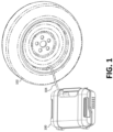
- Figure 1 illustrates a tire repair system 100 in accordance with an aspect of this disclosure being used to seal and/or inflate a tire 102, such as an automobile tire.
- the tire repair system 100 may be coupled to the tire 102 via a hose 104.
- the hose 104 may inject compressed gas (e.g., air) and a sealant from a sealant container (e.g., from a reservoir cartridge) into the tire 102 in order to repair the tire 102 and re-inflate the tire 102.
- compressed gas e.g., air
- a sealant container e.g., from a reservoir cartridge
- the tire repair system 100 may be used in a first mode of operation in which both compressed air and sealant are injected into the tire 102 or a second mode of operation in which only compressed air from the compressor is injected into the tire 102.
- the tire repair system 100 may use any type of sealant (e.g., emergency tire sealant) including, for example, Slime TM brand sealant.
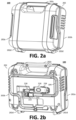
- Figures 2a and 2b illustrate, respectively, top and bottom isometric views of an example tire repair system 100 in a closed position in accordance with an aspect of this disclosure.
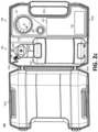
- Figures 2c and 2d illustrate, respectively, top and bottom plan views of the example tire repair system 100 in an open position.
- the various components of the tire repair system 100 are positioned in and/or integrated with a carrying case 202.
- the carrying case 202 is illustrated as a clam-shell style carrying case 202 with an upper housing 202a hingedly coupled to a lower housing 202b via one or more hinges 202d.
- the carrying case 202 includes an integrated carry handle 202c.
- the integrated carry handle 202c may be formed as part of the lower housing 202b.
- the carrying case 202 may be fabricated from a plastic material, such as acrylonitrile butadiene styrene (ABS), polypropylene (PP), polyethylene terephthalate (PET), high-density polyethylene (HDPE), polyvinyl chloride (PVC), low-density polyethylene (LDPE), polystyrene (PS), or a combination thereof.
- a plastic material such as acrylonitrile butadiene styrene (ABS), polypropylene (PP), polyethylene terephthalate (PET), high-density polyethylene (HDPE), polyvinyl chloride (PVC), low-density polyethylene (LDPE), polystyrene (PS), or a combination thereof.
- one or more components are transparent (e.g., clear, translucent, etc.).
- the upper housing 202a may be transparent to enable the user to observe and/or monitor the internal components during operation, such as the remaining volume of sealant. While a plastic
- the carrying case 202 generally houses an inflation system 204 and a sealant delivery system 206 that work in concert to inflate and/or repair the tire 102, such as a punctured automobile tire.
- the sealant is propelled into the inflatable tire 102 in order to repair a puncture in the tire 102.
- the tire repair system 100 may further include one or more controls, such as a start button 208, in or on the carrying case 202 that control the operation of the tire repair system 100.
- the tire repair system 100 repairs the tire 102 and fully inflates the tire 102 using the inflation system 204 and the sealant delivery system 206 via a single press of the start button 208.
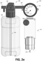
- Certain components of the inflation system 204 may be positioned within or behind a housing 210 of the carrying case 202 (e.g., a sub panel, cover, etc.) to, for example, improve aesthetics and/or to provide a surface upon which instructions may be provided. Therefore, for purposes of illustration, Figure 2e illustrates portions of the inflation system 204 and the sealant delivery system 206 separate from the carrying case 202.
- the illustrated inflation system 204 generally comprises a compressor 212, a gauge 214, and the start button 208.
- the compressor 212 can couple electrically to the vehicle via an electrical plug 216 and cable 218 to derive power needed to operate the tire repair system 100.
- the compressor 212 can be a small 12V DC gear-driven, piston-type compressor.
- the compressor 212 is configured to receive power from a standard 12-volt accessory outlet of the vehicle.
- the compressor 212 can also use 12V DC motor direct drive piston-type compressors, 120V AC powered compressors, and diesel motor driven truck air compressors.
- the compressor 212 can use a 5V DC supply from, for example, a universal serial bus (USB) port.
- USB universal serial bus
- the electrical plug 216 is illustrated as a connector for an automobile auxiliary power outlet (also known as car cigarette lighter or auxiliary power outlet), other connector formats and configurations are contemplated, such as USB connectors, barrel plugs, etc.
- a rechargeable battery pack 240 can be integrated with the carrying case 202 to power the various components, such as the compressor 212.
- the rechargeable battery pack 240 may be a rechargeable lithium battery for outputting a direct current (DC) voltage.
- Example lithium battery chemistries include lithium iron phosphate (LiFePO 4 ), lithium polymer (Li-poly), lithium-cobalt oxide (LiCoO 2 ), lithium-titanate, lithium-nickel manganese cobalt oxide (LiNiMnCoO 2 or NMC), lithium iron magnesium phosphate (LiFeMgPO 4 ), lithium-manganese oxide (LiMnO 2 ), lithium ion manganese oxide (Limn 2 O 4 , Li 2 MnO 3 , or LMO), etc.
- Other metal battery chemistries are possible, for example, aluminum-ion batteries.
- the rechargeable battery pack 240 need not be limited to a single battery or single battery cell.
- lithium iron phosphate batteries typically have a nominal cell voltage of about 3.2V to 3.3V each, while lithium-titanate batteries have a nominal cell voltage of about 2.4 V.
- multiple lithium cells may be connected in series to achieve a desired nominal voltage for the rechargeable battery pack 240.
- the nominal cell voltage is 3.2V to 3.3V
- four cells may be connected to achieve a nominal 12-volt accessory voltage of 12.8V to 13.2V.
- the rechargeable battery pack 240 may be recharged via, for example, the electrical plug 216. Providing a rechargeable battery pack 240 allows for operation of the tire repair system 100 when power is unavailable, which may be the case of non-motorized vehicles (e.g., trailers, bicycles, wagons, hand trucks, etc.) or when the vehicle has a discharged battery.
- non-motorized vehicles e.g., trailers, bicycles, wagons, hand trucks, etc.
- the compressor 212 is configured to provide compressed air (and, where applicable, tire sealant) to the tire via the hose 104 and a hose attachment 222.
- the hose attachment 222 may include a screw valve that connects to the tire 102 (e.g., via a valve stem of the tire 102). The screw valve of the hose attachment 222 opens when attached to the tire 102 and closes when disconnected from the tire 102 to prevent spray and dripping of compressed air and the sealant fluid.
- the compressed air is first passed through the sealant delivery system 206 where it mixes with tire sealant prior to delivery to the tire 102.
- the gauge 214 is configured to display the status of the tire repair system 100 and/or the pressure in the tire 102, usually measured in pounds per square inch (psi).
- the gauge 214 provides, for example, the pressure of the tire 102 so that the user of the device can inflate the tire 102 to the proper pressure as over-inflation and/or under-inflation are detrimental to the tire 102.
- a display device 224 can be positioned in or on the housing 210 to guide the operator when using the tire repair system 100.
- the display device 224 may be passive (e.g., printed matter, a placard, a sticker, etc.) or active (e.g., a light-emitting diode (LED) display, a liquid-crystal display (LCD) display, etc.).
- active e.g., a light-emitting diode (LED) display, a liquid-crystal display (LCD) display, etc.
- the display device 224 may provide information in addition to or in lieu of the display gauge 214.
- the illustrated sealant delivery system 206 generally comprises a reservoir cartridge 226 and a coupling valve 228.
- the reservoir cartridge 226, illustrated as a sealant bottle, is configured to house a volume of tire sealant.
- the reservoir cartridge 226 may store 20 ounces or more of emergency tire sealant; thought smaller volumes can be employed for other applications.
- the reservoir cartridge 226 may store 14 to 18 ounces of emergency tire sealant.
- the reservoir cartridge 226 may be removably coupled to the tire repair system 100 via the coupling valve 228 to allow for the reservoir cartridge 226 to be refilled and/or replaced once depleted.
- a switch 236, illustrated as a slider switch can be slid form a locked position toward an unlocked position to release or otherwise disengage the reservoir cartridge 226 from the carrying case 202. While the switch 236 is illustrated as a slider switch in this example, a spring-loaded lever may be employed instead (an example of which is illustrated and described in connection with Figures 3a and 3b ).
- the reservoir cartridge 226 is fluidly coupled to the hose 104 via the coupling valve 228 to allow for the tire sealant to mix with the compressed air from the inflation system 204 prior to delivery to the tire via the hose 104 and the hose attachment 222.
- the hose 104 is connected to the sealant delivery system 206 by the coupling valve 228. That is, the coupling valve 228 is configured to couple the reservoir cartridge 226 to the sealant delivery system 206 so that sealant may be injected into the tire 102 with the compressor air and the coupling valve 228 that couples the reservoir cartridge 226 to the tire repair system 100.
- the tire repair system 100 is configured to draw sealant from the reservoir cartridge 226 via a dip tube 242 (represented in dotted lines) configured to draw sealant from the bottom and/or lowest point of the reservoir cartridge 226.
- the sealant can be drawn or pushed through the dip tube 242 using, for example, the compressed air.
- the sealant delivery system 206 can also include a cutoff valve 230 to disable the sealant delivery system 206 when not in use.
- the cutoff valve 230 can be in addition to, in lieu of, or combined with the valve 238.
- the cutoff valve 230 may use a knob, dial, switch, or the like.
- the cutoff valve 230 is positioned fluidly between the reservoir cartridge 226 and the hose 104. For example, to avoid unwanted discharge of tire sealant and/or to inflate a tire without delivering tire sealant, the cutoff valve 230 may be moved from an open position (e.g., the first mode of operation) to a closed position (e.g., the second mode of operation).
- the cutoff valve 230 can be used to select the mode of operation of the tire repair system 100 by switching the cutoff valve 230 between the air-only operation and the air and sealant mode of operation so that the tire repair system 100 may be used to inflate an tire 102 and/or repair and inflate a damaged tire 102. Therefore, the cutoff valve 230 can be configured to switch the tire repair system 100 between the first mode of operation and the second mode of operation, where only compressed air is provided in the first mode of operation and both compressed air and sealant are provided in the second mode of operation.
- the carrying case 202 may be formed with one or more exterior recesses or pockets to retain components of the tire repair system 100.
- Each of the one or more exterior recesses includes a clip, pressure fitting, or the like to secure a desired element.
- the lower housing 202b can define a hose attachment recess 232 configured to retain the hose attachment 222 and an electrical plug recess 234 configured to retain the electrical plug 216. Storing the electrical plug 216 and/or the hose attachment 222 on an external surface enables the operator to use the tire repair system 100 without having to open the carrying case 202.
- the start button 208 is illustrated within a cavity/volume of the carrying case 202, in some examples, the start button 208 may likewise be positioned on an exterior surface or otherwise accessible from the exterior. In one example, the start button 208 is position on an external surface of the lower housing 202b, such as the sides or backside. In another example, the upper housing 202a, which may be transparent, may be fabricated with a button-extender assembly that, when engaged, advances a post, a rod, or otherwise into a cavity of the carrying case 202 to engage the start button 208.
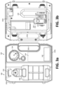
- Figures 3a and 3b illustrate, respectively, top and bottom plan views of the example tire repair system 100 in accordance with an another aspect of this disclosure.
- the tire repair system 100 is illustrated with the upper housing 202a detached from the lower housing 202b via the one or more hinges 202d.
- the tire repair system 100 of Figures 3a and 3b is substantially the same as the tire repair system 100 of Figures 2a through 2d and the components are number accordingly, but with certain exception.
- the switch 236 can be provided as a spring-loaded lever instead of the slider switch illustrated in Figure 2c .
- the indicia (e.g., numerals, arrows, etc.) of the display gauge 214 can be oriented such that the display gauge 214 is more easily viewed from the edge of the lower hosing 202b having the integrated carry handle 202c positioned or formed thereon. Further, certain components can be stowed or arranged differently (e.g., on the lower housing 202b).
- the hose attachment recess 232 and the electrical plug recess 234 can be positioned such that they are adjacent one another.
- Such an arrangement can enable to operator to more easily detach or otherwise remove the electrical plug 216 and/or the hose attachment 222 from the lower housing 202b.
- a single, larger, recess can be formed to serve as both the hose attachment recess 232 and the electrical plug recess 234.
Landscapes
- Engineering & Computer Science (AREA)
- Mechanical Engineering (AREA)
- General Engineering & Computer Science (AREA)
Abstract
Description
- This application claims the benefit of and priority to
U.S. provisional patent application Ser. No. 63/410,357, filed September 27, 2023 - This present disclosure relates to a tire repair and inflation system and apparatus. For the average motorist, replacing a tire on the side of the road can be daunting and needlessly exposes the motorist to inherent roadside dangers.
- One solutions to an emergency flat tire repair is to use an aerosol sealant dispenser that combines a chemical fluid and a propellant. These are usually contained in a can or other type of container. A tube is attached between the can and a tire via a tire valve stem. The fluid is propelled through the valve stem into the tire. When the fluid flows through a tire puncture, the fluid hardens with exposure to air. This forms a repair of the tire. To enhance the seal, a compressed air source can be used to allow proper and safe inflation of the tire. An example integrated compressor-tire sealant injection device with a large mouth sealant container is described in commonly owned
U.S. Patent No. 6,789,581 to David Cowan et al. andU.S. Patent No. 7,798,183 to James Cegelski and Scott Noble Hickman . - Despite existing solutions, it is desirable to provide a portable two-part system with an integrated compressor device and sealant container that overcomes the limitations of existing tire repair sealants, systems, and devices.
- The present disclosure relates generally to a tire repair and inflation system and apparatus, substantially as illustrated by and described in connection with at least one of the figures, as set forth more completely in the claims.
- The foregoing and other objects, features, and advantages of the devices, systems, and methods described herein will be apparent from the following description of particular examples thereof, as illustrated in the accompanying figures; where like or similar reference numbers refer to like or similar structures. The figures are not necessarily to scale, emphasis instead being placed upon illustrating the principles of the devices, systems, and methods described herein.
-
Figure 1 illustrates a tire repair system in accordance with an aspect of this disclosure being used to seal and/or inflate a tire. -
Figures 2a and 2b illustrate, respectively, top and bottom isometric views of the example tire repair system in a closed position. -
Figures 2c and2d illustrate, respectively, top and bottom plan views of the example tire repair system in an open position. -
Figure 2e illustrates the major components of the inflation system and the sealant delivery system separate from the carrying case. -
Figures 3a and 3b illustrate, respectively, top and bottom plan views of the example tire repair system in accordance with an another aspect of this disclosure. - References to items in the singular should be understood to include items in the plural, and vice versa, unless explicitly stated otherwise or clear from the text. Grammatical conjunctions are intended to express any and all disjunctive and conjunctive combinations of conjoined clauses, sentences, words, and the like, unless otherwise stated or clear from the context. Recitation of ranges of values herein are not intended to be limiting, referring instead individually to any and all values falling within and/or including the range, unless otherwise indicated herein, and each separate value within such a range is incorporated into the specification as if it were individually recited herein. In the following description, it is understood that terms such as "first," "second," "top," "bottom," "side," "front," "back," "upper," "lower," and the like are words of convenience and are not to be construed as limiting terms. For example, while in some examples a first side is located adjacent or near a second side, the terms "first side" and "second side" do not imply any specific order in which the sides are ordered.
- The terms "about," "approximately," "substantially," or the like, when accompanying a numerical value, are to be construed as indicating a deviation as would be appreciated by one of ordinary skill in the art to operate satisfactorily for an intended purpose. Ranges of values and/or numeric values are provided herein as examples only, and do not constitute a limitation on the scope of the disclosure. The use of any and all examples, or exemplary language ("e.g.," "such as," or the like) provided herein, is intended merely to better illuminate the disclosed examples and does not pose a limitation on the scope of the disclosure. The terms "e.g.," and "for example" set off lists of one or more non-limiting examples, instances, or illustrations. No language in the specification should be construed as indicating any unclaimed element as essential to the practice of the disclosed examples.
- The term "and/or" means any one or more of the items in the list joined by "and/or." As an example, "x and/or y" means any element of the three-element set {(x), (y), (x, y)}. In other words, "x and/or y" means "one or both of x and y". As another example, "x, y, and/or z" means any element of the seven-element set {(x), (y), (z), (x, y), (x, z), (y, z), (x, y, z)}. In other words, "x, y, and/or z" means "one or more of x, y, and z."
- Disclosed is a portable two-part system with an integrated compressor device and sealant container. In one example, a tire repair system for inflating or repairing a tire comprises: a carrying case; an inflation system positioned in or integrated with the carrying case, wherein the inflation system is configured to provide compressed air; a sealant delivery system positioned in or integrated with the carrying case, wherein the sealant delivery system is configured to mix a tire sealant with the compressed air; and a hose attachment configured to engage the tire and to deliver the tire sealant and the compressed air to the tire.
- In some examples, the carrying case includes an upper housing hingedly coupled to a lower housing via one or more hinges. In some examples, the upper housing is transparent. In some examples, the carrying case is formed with an exterior recess to retain a component of the tire repair system. In some examples, the carrying case is formed with a hose attachment recess to retain the hose attachment.
- In some examples, the inflation system comprises an electrical plug configured to couple electrically to a 12-volt accessory outlet of a vehicle. In some examples, the carrying case is formed with an electrical plug recess to retain the electrical plug.
- In some examples, the inflation system comprises a gauge that is configured to display a pressure of the tire. In some examples, the inflation system comprises a start button. In some examples, the sealant delivery system comprises a reservoir cartridge and a coupling valve. In some examples, the reservoir cartridge is removably coupled via the coupling valve.
- In some examples, the tire repair system further comprises a switch configured to disengage the reservoir cartridge from the carrying case. In some examples, the tire repair system further comprises a cutoff valve configured to switch the tire repair system between a first mode of operation and a second mode of operation. In some examples, only compressed air is provided in the first mode of operation and both compressed air and sealant are provided in the second mode of operation.
- In some examples, the tire repair system further comprises a rechargeable battery pack positioned in or integrated with the carrying case, wherein the rechargeable battery pack is configured to power the inflation system. In some examples, the inflation system comprises an electrical plug configured to couple electrically to a universal serial bus (USB) port.
-
Figure 1 illustrates atire repair system 100 in accordance with an aspect of this disclosure being used to seal and/or inflate atire 102, such as an automobile tire. In the illustrated example, thetire repair system 100 may be coupled to thetire 102 via ahose 104. As will be discussed, thehose 104 may inject compressed gas (e.g., air) and a sealant from a sealant container (e.g., from a reservoir cartridge) into thetire 102 in order to repair thetire 102 and re-inflate thetire 102. In some examples, thetire repair system 100 may be used in a first mode of operation in which both compressed air and sealant are injected into thetire 102 or a second mode of operation in which only compressed air from the compressor is injected into thetire 102. Thetire repair system 100 may use any type of sealant (e.g., emergency tire sealant) including, for example, Slime™ brand sealant. -
Figures 2a and 2b illustrate, respectively, top and bottom isometric views of an exampletire repair system 100 in a closed position in accordance with an aspect of this disclosure.Figures 2c and2d illustrate, respectively, top and bottom plan views of the exampletire repair system 100 in an open position. - As illustrated, the various components of the
tire repair system 100 are positioned in and/or integrated with a carryingcase 202. The carryingcase 202 is illustrated as a clam-shellstyle carrying case 202 with anupper housing 202a hingedly coupled to alower housing 202b via one ormore hinges 202d. In some examples, the carryingcase 202 includes an integratedcarry handle 202c. The integrated carryhandle 202c may be formed as part of thelower housing 202b. The carryingcase 202, or components thereof, may be fabricated from a plastic material, such as acrylonitrile butadiene styrene (ABS), polypropylene (PP), polyethylene terephthalate (PET), high-density polyethylene (HDPE), polyvinyl chloride (PVC), low-density polyethylene (LDPE), polystyrene (PS), or a combination thereof. In some examples, one or more components are transparent (e.g., clear, translucent, etc.). For example, theupper housing 202a may be transparent to enable the user to observe and/or monitor the internal components during operation, such as the remaining volume of sealant. While a plastic material is described, other materials can be used, such as metal. - The carrying
case 202 generally houses aninflation system 204 and asealant delivery system 206 that work in concert to inflate and/or repair thetire 102, such as a punctured automobile tire. The sealant is propelled into theinflatable tire 102 in order to repair a puncture in thetire 102. Thetire repair system 100 may further include one or more controls, such as astart button 208, in or on the carryingcase 202 that control the operation of thetire repair system 100. In some examples, thetire repair system 100 repairs thetire 102 and fully inflates thetire 102 using theinflation system 204 and thesealant delivery system 206 via a single press of thestart button 208. - Certain components of the
inflation system 204 may be positioned within or behind ahousing 210 of the carrying case 202 (e.g., a sub panel, cover, etc.) to, for example, improve aesthetics and/or to provide a surface upon which instructions may be provided. Therefore, for purposes of illustration,Figure 2e illustrates portions of theinflation system 204 and thesealant delivery system 206 separate from the carryingcase 202. - The illustrated
inflation system 204 generally comprises acompressor 212, agauge 214, and thestart button 208. In some examples, thecompressor 212 can couple electrically to the vehicle via anelectrical plug 216 andcable 218 to derive power needed to operate thetire repair system 100. Thecompressor 212 can be a small 12V DC gear-driven, piston-type compressor. In one example, thecompressor 212 is configured to receive power from a standard 12-volt accessory outlet of the vehicle. In other examples, thecompressor 212 can also use 12V DC motor direct drive piston-type compressors, 120V AC powered compressors, and diesel motor driven truck air compressors. In yet other examples, thecompressor 212 can use a 5V DC supply from, for example, a universal serial bus (USB) port. To that end, while theelectrical plug 216 is illustrated as a connector for an automobile auxiliary power outlet (also known as car cigarette lighter or auxiliary power outlet), other connector formats and configurations are contemplated, such as USB connectors, barrel plugs, etc. - Additionally or alternatively, a
rechargeable battery pack 240 can be integrated with the carryingcase 202 to power the various components, such as thecompressor 212. Therechargeable battery pack 240 may be a rechargeable lithium battery for outputting a direct current (DC) voltage. Example lithium battery chemistries include lithium iron phosphate (LiFePO4), lithium polymer (Li-poly), lithium-cobalt oxide (LiCoO2), lithium-titanate, lithium-nickel manganese cobalt oxide (LiNiMnCoO2 or NMC), lithium iron magnesium phosphate (LiFeMgPO4), lithium-manganese oxide (LiMnO2), lithium ion manganese oxide (Limn2O4, Li2MnO3, or LMO), etc. Other metal battery chemistries are possible, for example, aluminum-ion batteries. - The
rechargeable battery pack 240 need not be limited to a single battery or single battery cell. For example, lithium iron phosphate batteries typically have a nominal cell voltage of about 3.2V to 3.3V each, while lithium-titanate batteries have a nominal cell voltage of about 2.4 V. Accordingly, multiple lithium cells may be connected in series to achieve a desired nominal voltage for therechargeable battery pack 240. For example, where the nominal cell voltage is 3.2V to 3.3V, four cells may be connected to achieve a nominal 12-volt accessory voltage of 12.8V to 13.2V. - The
rechargeable battery pack 240 may be recharged via, for example, theelectrical plug 216. Providing arechargeable battery pack 240 allows for operation of thetire repair system 100 when power is unavailable, which may be the case of non-motorized vehicles (e.g., trailers, bicycles, wagons, hand trucks, etc.) or when the vehicle has a discharged battery. - The
compressor 212 is configured to provide compressed air (and, where applicable, tire sealant) to the tire via thehose 104 and ahose attachment 222. Thehose attachment 222 may include a screw valve that connects to the tire 102 (e.g., via a valve stem of the tire 102). The screw valve of thehose attachment 222 opens when attached to thetire 102 and closes when disconnected from thetire 102 to prevent spray and dripping of compressed air and the sealant fluid. - In the illustrated example, the compressed air is first passed through the
sealant delivery system 206 where it mixes with tire sealant prior to delivery to thetire 102. Thegauge 214 is configured to display the status of thetire repair system 100 and/or the pressure in thetire 102, usually measured in pounds per square inch (psi). Thegauge 214 provides, for example, the pressure of thetire 102 so that the user of the device can inflate thetire 102 to the proper pressure as over-inflation and/or under-inflation are detrimental to thetire 102. - As illustrated, a
display device 224 can be positioned in or on thehousing 210 to guide the operator when using thetire repair system 100. Thedisplay device 224 may be passive (e.g., printed matter, a placard, a sticker, etc.) or active (e.g., a light-emitting diode (LED) display, a liquid-crystal display (LCD) display, etc.). In some examples, such as the situation of adisplay device 224 that is active, thedisplay device 224 may provide information in addition to or in lieu of thedisplay gauge 214. - The illustrated
sealant delivery system 206 generally comprises areservoir cartridge 226 and acoupling valve 228. Thereservoir cartridge 226, illustrated as a sealant bottle, is configured to house a volume of tire sealant. In some examples, thereservoir cartridge 226 may store 20 ounces or more of emergency tire sealant; thought smaller volumes can be employed for other applications. In one example, thereservoir cartridge 226 may store 14 to 18 ounces of emergency tire sealant. Thereservoir cartridge 226 may be removably coupled to thetire repair system 100 via thecoupling valve 228 to allow for thereservoir cartridge 226 to be refilled and/or replaced once depleted. In some examples, aswitch 236, illustrated as a slider switch, can be slid form a locked position toward an unlocked position to release or otherwise disengage thereservoir cartridge 226 from the carryingcase 202. While theswitch 236 is illustrated as a slider switch in this example, a spring-loaded lever may be employed instead (an example of which is illustrated and described in connection withFigures 3a and 3b ). - The
reservoir cartridge 226 is fluidly coupled to thehose 104 via thecoupling valve 228 to allow for the tire sealant to mix with the compressed air from theinflation system 204 prior to delivery to the tire via thehose 104 and thehose attachment 222. As best illustrated inFigure 2e , thehose 104 is connected to thesealant delivery system 206 by thecoupling valve 228. That is, thecoupling valve 228 is configured to couple thereservoir cartridge 226 to thesealant delivery system 206 so that sealant may be injected into thetire 102 with the compressor air and thecoupling valve 228 that couples thereservoir cartridge 226 to thetire repair system 100. In some examples, rather than relying on gravity, thetire repair system 100 is configured to draw sealant from thereservoir cartridge 226 via a dip tube 242 (represented in dotted lines) configured to draw sealant from the bottom and/or lowest point of thereservoir cartridge 226. The sealant can be drawn or pushed through thedip tube 242 using, for example, the compressed air. - In operation, when the
reservoir cartridge 226 is coupled to the device as illustrated, compressed gas from theinflation system 204 passes through thecoupling valve 228 into thereservoir cartridge 226 and then exits thereservoir cartridge 226 with the sealant through thehose 104 when thehose 104 is connected to thetire 102. In this manner, the sealant does not comes into contact with theinflation system 204. Back flow can be prevented using a valve 238 in thecoupling valve 228, such as a ball check valve. In addition, ball valve 238 ensures that, when not in operation, the sealant is sealed (by the ball valve) so that the sealant in thereservoir cartridge 226 does not harden or leak. - The
sealant delivery system 206 can also include acutoff valve 230 to disable thesealant delivery system 206 when not in use. Thecutoff valve 230 can be in addition to, in lieu of, or combined with the valve 238. Thecutoff valve 230 may use a knob, dial, switch, or the like. Thecutoff valve 230 is positioned fluidly between thereservoir cartridge 226 and thehose 104. For example, to avoid unwanted discharge of tire sealant and/or to inflate a tire without delivering tire sealant, thecutoff valve 230 may be moved from an open position (e.g., the first mode of operation) to a closed position (e.g., the second mode of operation). Therefore, thecutoff valve 230 can be used to select the mode of operation of thetire repair system 100 by switching thecutoff valve 230 between the air-only operation and the air and sealant mode of operation so that thetire repair system 100 may be used to inflate antire 102 and/or repair and inflate a damagedtire 102. Therefore, thecutoff valve 230 can be configured to switch thetire repair system 100 between the first mode of operation and the second mode of operation, where only compressed air is provided in the first mode of operation and both compressed air and sealant are provided in the second mode of operation. - As best illustrated in
Figure 2d , the carryingcase 202 may be formed with one or more exterior recesses or pockets to retain components of thetire repair system 100. Each of the one or more exterior recesses includes a clip, pressure fitting, or the like to secure a desired element. For example, thelower housing 202b can define ahose attachment recess 232 configured to retain thehose attachment 222 and anelectrical plug recess 234 configured to retain theelectrical plug 216. Storing theelectrical plug 216 and/or thehose attachment 222 on an external surface enables the operator to use thetire repair system 100 without having to open the carryingcase 202. To that end, while thestart button 208 is illustrated within a cavity/volume of the carryingcase 202, in some examples, thestart button 208 may likewise be positioned on an exterior surface or otherwise accessible from the exterior. In one example, thestart button 208 is position on an external surface of thelower housing 202b, such as the sides or backside. In another example, theupper housing 202a, which may be transparent, may be fabricated with a button-extender assembly that, when engaged, advances a post, a rod, or otherwise into a cavity of the carryingcase 202 to engage thestart button 208. -
Figures 3a and 3b illustrate, respectively, top and bottom plan views of the exampletire repair system 100 in accordance with an another aspect of this disclosure. In this example, thetire repair system 100 is illustrated with theupper housing 202a detached from thelower housing 202b via the one ormore hinges 202d. Thetire repair system 100 ofFigures 3a and 3b is substantially the same as thetire repair system 100 ofFigures 2a through 2d and the components are number accordingly, but with certain exception. - As best illustrated in
Figure 3a , theswitch 236 can be provided as a spring-loaded lever instead of the slider switch illustrated inFigure 2c . In addition, the indicia (e.g., numerals, arrows, etc.) of thedisplay gauge 214 can be oriented such that thedisplay gauge 214 is more easily viewed from the edge of thelower hosing 202b having the integratedcarry handle 202c positioned or formed thereon. Further, certain components can be stowed or arranged differently (e.g., on thelower housing 202b). For example, with reference toFigure 3b , thehose attachment recess 232 and theelectrical plug recess 234 can be positioned such that they are adjacent one another. Such an arrangement can enable to operator to more easily detach or otherwise remove theelectrical plug 216 and/or thehose attachment 222 from thelower housing 202b. In some examples, a single, larger, recess can be formed to serve as both thehose attachment recess 232 and theelectrical plug recess 234. - While the present method and/or system has been described with reference to certain implementations, it will be understood by those skilled in the art that various changes may be made and equivalents may be substituted without departing from the scope of the present method and/or system. In addition, many modifications may be made to adapt a particular situation or material to the teachings of the present disclosure without departing from its scope. For example, block and/or components of disclosed examples may be combined, divided, re-arranged, and/or otherwise modified. Therefore, the present method and/or system are not limited to the particular implementations disclosed. Instead, the present method and/or system will include all implementations falling within the scope of the appended claims, both literally and under the doctrine of equivalents.
- Certain embodiments of the invention are described in the following clauses:
- Clause 1. A tire repair system (100) for inflating or repairing a tire, the tire repair system (100) comprising:
- a carrying case (202);
- an inflation system (204) positioned in or integrated with the carrying case (202), wherein the inflation system (204) is configured to provide compressed air;
- a sealant delivery system (206) positioned in or integrated with the carrying case (202), wherein the sealant delivery system (206) is configured to mix a tire sealant with the compressed air; and
- a hose attachment (222) configured to engage the tire and to deliver the tire sealant and the compressed air to the tire.
- Clause 2. The tire repair system (100) of clause 1, wherein the carrying case (202) includes an upper housing (202a) hingedly coupled to a lower housing (202b) via one or more hinges (202d).
- Clause 3. The tire repair system (100) of clause 2, wherein the upper housing (202a) is transparent.
- Clause 4. The tire repair system (100) of clause 1, wherein the carrying case (202) is formed with an exterior recess to retain a component of the tire repair system (100).
-
Clause 5. The tire repair system (100) of clause 1, wherein the carrying case (202) is formed with a hose attachment recess (232) to retain the hose attachment (222). - Clause 6. The tire repair system (100) of clause 1, wherein the inflation system (204) comprises an electrical plug (216) configured to couple electrically to a 12-volt accessory outlet of a vehicle.
- Clause 7. The tire repair system (100) of clause 1, wherein the carrying case (202) is formed with an electrical plug recess (234) to retain the electrical plug (216).
- Clause 8. The tire repair system (100) of clause 1, wherein the inflation system (204) comprises a gauge (214) that is configured to display a pressure of the tire.
- Clause 9. The tire repair system (100) of clause 1, wherein the inflation system (204) comprises a start button (208).
-
Clause 10. The tire repair system (100) of clause 1, wherein the sealant delivery system (206) comprises a reservoir cartridge (226) and a coupling valve (228). - Clause 11. The tire repair system (100) of
clause 10, wherein the reservoir cartridge (226) is removably coupled via the coupling valve (228). - Clause 12. The tire repair system (100) of clause 11, further comprising a switch (236) configured to disengage the reservoir cartridge (226) from the carrying case (202).
- Clause 13. The tire repair system (100) of clause 1, further comprising a cutoff valve (230) configured to switch the tire repair system (100) between a first mode of operation and a second mode of operation.
- Clause 14. The tire repair system (100) of clause 13, wherein only compressed air is provided in the first mode of operation and both compressed air and sealant are provided in the second mode of operation.
- Clause 15. The tire repair system (100) of clause 1, further comprising a rechargeable battery pack (240) positioned in or integrated with the carrying case (202), wherein the rechargeable battery pack (240) is configured to power the inflation system (204).
- Clause 16. The tire repair system (100) of clause 1, wherein the inflation system (204) comprises an electrical plug (216) configured to couple electrically to a universal serial bus (USB) port.
- Clause 17. A tire repair system (100) for inflating or repairing a tire, the tire repair system (100) comprising:
- a carrying case (202), wherein the carrying case (202) includes an upper housing (202a) hingedly coupled to a lower housing (202b) via one or more hinges (202d);
- an inflation system (204) positioned in or integrated with the carrying case (202), wherein the inflation system (204) is configured to provide compressed air;
- a sealant delivery system (206) positioned in or integrated with the carrying case (202), wherein the sealant delivery system (206) is configured to mix a tire sealant with the compressed air; and
- a hose attachment (222) configured to engage the tire and to deliver the tire sealant and the compressed air to the tire.
- Clause 18. The tire repair system (100) of clause 17, further comprising a cutoff valve (230) configured to switch the tire repair system (100) between a first mode of operation where only compressed air is provided and a second mode of operation where both compressed air and sealant are provided.
- Clause 19. The tire repair system (100) of clause 17, further comprising a rechargeable battery pack (240) positioned in or integrated with the carrying case (202), wherein the rechargeable battery pack (240) is configured to power the inflation system (204).
-
Clause 20. A tire repair system (100) for inflating or repairing a tire, the tire repair system (100) comprising:- a carrying case (202);
- an inflation system (204) positioned in or integrated with the carrying case (202), wherein the inflation system (204) is configured to provide compressed air;
- a sealant delivery system (206) positioned in or integrated with the carrying case (202), wherein the sealant delivery system (206) is configured to mix a tire sealant with the compressed air;
- a hose attachment (222) configured to engage the tire and to deliver the tire sealant and the compressed air to the tire; and
- a rechargeable battery pack (240) positioned in or integrated with the carrying case (202), wherein the rechargeable battery pack (240) is configured to power the inflation system (204).
Claims (15)
- A tire repair system (100) for inflating or repairing a tire, the tire repair system (100) comprising:a carrying case (202);an inflation system (204) positioned in or integrated with the carrying case (202), wherein the inflation system (204) is configured to provide compressed air;a sealant delivery system (206) positioned in or integrated with the carrying case (202), wherein the sealant delivery system (206) is configured to mix a tire sealant with the compressed air; anda hose attachment (222) configured to engage the tire and to deliver the tire sealant and the compressed air to the tire.
- The tire repair system (100) of claim 1, wherein the carrying case (202) includes an upper housing (202a) hingedly coupled to a lower housing (202b) via one or more hinges (202d), and optionally wherein the upper housing (202a) is transparent.
- The tire repair system (100) of claim 1, wherein the carrying case (202) is formed with an exterior recess to retain a component of the tire repair system (100).
- The tire repair system (100) of claim 1, wherein the carrying case (202) is formed with a hose attachment recess (232) to retain the hose attachment (222).
- The tire repair system (100) of claim 1, wherein the inflation system (204) comprises an electrical plug (216) configured to couple electrically to a 12-volt accessory outlet of a vehicle.
- The tire repair system (100) of claim 1, wherein the carrying case (202) is formed with an electrical plug recess (234) to retain the electrical plug (216).
- The tire repair system (100) of claim 1, wherein the inflation system (204) comprises a gauge (214) that is configured to display a pressure of the tire.
- The tire repair system (100) of claim 1, wherein the inflation system (204) comprises a start button (208).
- The tire repair system (100) of claim 1, wherein the sealant delivery system (206) comprises a reservoir cartridge (226) and a coupling valve (228), and optionally wherein the reservoir cartridge (226) is removably coupled via the coupling valve (228), and optionally further comprising a switch (236) configured to disengage the reservoir cartridge (226) from the carrying case (202).
- The tire repair system (100) of claim 1, further comprising a cutoff valve (230) configured to switch the tire repair system (100) between a first mode of operation and a second mode of operation, and optionally wherein only compressed air is provided in the first mode of operation and both compressed air and sealant are provided in the second mode of operation.
- The tire repair system (100) of claim 1, further comprising a rechargeable battery pack (240) positioned in or integrated with the carrying case (202), wherein the rechargeable battery pack (240) is configured to power the inflation system (204), or wherein the inflation system (204) comprises an electrical plug (216) configured to couple electrically to a universal serial bus (USB) port.
- A tire repair system (100) for inflating or repairing a tire, the tire repair system (100) comprising:a carrying case (202), wherein the carrying case (202) includes an upper housing (202a) hingedly coupled to a lower housing (202b) via one or more hinges (202d);an inflation system (204) positioned in or integrated with the carrying case (202), wherein the inflation system (204) is configured to provide compressed air;a sealant delivery system (206) positioned in or integrated with the carrying case (202), wherein the sealant delivery system (206) is configured to mix a tire sealant with the compressed air; anda hose attachment (222) configured to engage the tire and to deliver the tire sealant and the compressed air to the tire.
- The tire repair system (100) of claim 12, further comprising a cutoff valve (230) configured to switch the tire repair system (100) between a first mode of operation where only compressed air is provided and a second mode of operation where both compressed air and sealant are provided.
- The tire repair system (100) of claim 12, further comprising a rechargeable battery pack (240) positioned in or integrated with the carrying case (202), wherein the rechargeable battery pack (240) is configured to power the inflation system (204).
- A tire repair system (100) for inflating or repairing a tire, the tire repair system (100) comprising:a carrying case (202);an inflation system (204) positioned in or integrated with the carrying case (202), wherein the inflation system (204) is configured to provide compressed air;a sealant delivery system (206) positioned in or integrated with the carrying case (202), wherein the sealant delivery system (206) is configured to mix a tire sealant with the compressed air;a hose attachment (222) configured to engage the tire and to deliver the tire sealant and the compressed air to the tire; anda rechargeable battery pack (240) positioned in or integrated with the carrying case (202), wherein the rechargeable battery pack (240) is configured to power the inflation system (204).
Applications Claiming Priority (2)
| Application Number | Priority Date | Filing Date | Title |
|---|---|---|---|
| US202263410357P | 2022-09-27 | 2022-09-27 | |
| US18/239,499 US12502854B2 (en) | 2022-09-27 | 2023-08-29 | Tire repair system |
Publications (1)
| Publication Number | Publication Date |
|---|---|
| EP4353461A1 true EP4353461A1 (en) | 2024-04-17 |
Family
ID=88147314
Family Applications (1)
| Application Number | Title | Priority Date | Filing Date |
|---|---|---|---|
| EP23198804.9A Pending EP4353461A1 (en) | 2022-09-27 | 2023-09-21 | Tire repair system |
Country Status (2)
| Country | Link |
|---|---|
| US (1) | US12502854B2 (en) |
| EP (1) | EP4353461A1 (en) |
Families Citing this family (3)
| Publication number | Priority date | Publication date | Assignee | Title |
|---|---|---|---|---|
| US12502854B2 (en) | 2022-09-27 | 2025-12-23 | Illinois Tool Works Inc. | Tire repair system |
| USD1065007S1 (en) * | 2022-09-30 | 2025-03-04 | Illinois Tool Works Inc. | Tire repair system |
| USD1066212S1 (en) * | 2022-09-30 | 2025-03-11 | Illinois Tool Works Inc. | Tire repair system |
Citations (9)
| Publication number | Priority date | Publication date | Assignee | Title |
|---|---|---|---|---|
| EP0972616A2 (en) * | 1998-07-17 | 2000-01-19 | Continental Aktiengesellschaft | Repair kit and its portable container |
| US6789581B2 (en) | 2002-10-31 | 2004-09-14 | Interdynamics, Inc. | Apparatus for sealing, inflating, and repairing tires |
| US20070221287A1 (en) * | 2004-05-20 | 2007-09-27 | Bridgestone Corporation | Sealing agent injecting apparatus, sealing agent injecting method and sealing pump up apparatus |
| EP2103417A1 (en) * | 2006-12-12 | 2009-09-23 | Bridgestone Corporation | Sealing and pumping device |
| EP2163374A1 (en) * | 2007-06-18 | 2010-03-17 | Bridgestone Corporation | Sealing/pump-up device |
| US7798183B2 (en) | 2006-10-26 | 2010-09-21 | Illinois Tool Works Inc. | Integrated compressor-tire sealant injection device with large mouth sealant container |
| CN104276151A (en) * | 2014-09-12 | 2015-01-14 | 广州市文澳电子科技有限公司 | Multifunctional emergency device of motor vehicle |
| CN204278561U (en) * | 2014-11-27 | 2015-04-22 | 王名宪 | Air compressor capable of inflating and repairing tires |
| US20200086595A1 (en) * | 2016-02-17 | 2020-03-19 | Trydel Research Pty Ltd | Improved apparatus for sealing and inflation of damaged inflatable articles, such as punctured tires |
Family Cites Families (67)
| Publication number | Priority date | Publication date | Assignee | Title |
|---|---|---|---|---|
| US3718238A (en) * | 1970-07-27 | 1973-02-27 | Polytop Corp | Safety dispensing closure |
| US3786964A (en) * | 1972-09-15 | 1974-01-22 | Eyelet Specialty Co | Safety mechanism for a liquid-dispensing container |
| US4081113A (en) * | 1976-03-11 | 1978-03-28 | Polytop Corporation | Child resistant dispensing closure |
| US4621984A (en) * | 1985-04-17 | 1986-11-11 | Air Shot, Inc. | Portable air pump |
| US5156853A (en) * | 1989-08-04 | 1992-10-20 | Werner Frank D | Windshield repair apparatus |
| US5104295A (en) * | 1990-10-30 | 1992-04-14 | Wong Alex Y K | Electric air pump with photo-electric cutoff of pressure dial |
| GB9101560D0 (en) * | 1991-01-24 | 1991-03-06 | Boc Group Plc | Fluid delivery system |
| US5427145A (en) * | 1993-10-07 | 1995-06-27 | Abbott Laboratories | Connector with integral valve |
| USD369240S (en) * | 1994-12-12 | 1996-04-30 | Southern Case, Inc. | Case for a video recorder |
| US5687777A (en) * | 1996-03-11 | 1997-11-18 | Ohmeda Inc. | Anesthetic agent filler valve |
| USD425913S (en) * | 1999-07-23 | 2000-05-30 | Bonzer Robert L | Clear case for an inflation kit |
| DE20122862U1 (en) | 2001-02-13 | 2008-09-11 | Doukas Ag | Device for dispensing tire sealant |
| ITTO20040117A1 (en) * | 2004-02-27 | 2004-05-27 | Tek Srl | INFLATION AND REPAIR KIT FOR INFLATABLE ITEMS, IN PARTICULAR TIRES |
| USD508058S1 (en) * | 2004-05-26 | 2005-08-02 | Yue Qin Wu | Pumping device |
| JP2006103144A (en) | 2004-10-05 | 2006-04-20 | Bridgestone Corp | Sealing / pump-up device |
| ITTO20060166A1 (en) * | 2006-03-07 | 2007-09-08 | Tek Srl | AUTOMATIC REPAIR AND INFLATION KIT FOR INFLATABLE OBJECTS PROVIDED WITH A SELECTOR VALVE |
| ITTO20060454A1 (en) * | 2006-06-20 | 2007-12-21 | Tek Srl | KIT FOR REPAIR AND INFLATION OF INFLATABLE ITEMS |
| JP5376754B2 (en) * | 2006-12-21 | 2013-12-25 | 株式会社ブリヂストン | Sealing device |
| ITTO20070101A1 (en) * | 2007-02-09 | 2008-08-10 | Tek Srl | VEHICLE INCLUDING A GROUP FOR THE REPAIR AND INFLATION OF INFLATABLE ITEMS AND ITS METHOD |
| ITTO20070610A1 (en) * | 2007-08-28 | 2009-02-28 | Tek Global Srl | SEALANT LIQUID CONTAINER UNIT AND KIT FOR REPAIR AND INFLATION OF INFLATABLE ITEMS PROVIDED WITH SUCH A CONTAINER |
| ITTO20070776A1 (en) | 2007-10-31 | 2009-05-01 | Tek Global Srl | KIT FOR REPAIR AND INFLATION OF INFLATABLE ITEMS PROVIDED WITH A CONTROL DEVICE |
| DE202007016242U1 (en) | 2007-11-21 | 2008-01-31 | Continental Aktiengesellschaft | Device with a switching mark for sealing and inflating inflatable objects |
| CN101977755A (en) * | 2008-03-25 | 2011-02-16 | 住友橡胶工业株式会社 | Tire puncture repair apparatus |
| ITTO20080493A1 (en) * | 2008-06-23 | 2009-12-24 | Tek Global Srl | KIT FOR REPAIR AND INFLATION OF INFLATABLE ARTICLES PROVIDED WITH A PERFECT MANOMETER AND ITS METHOD |
| WO2010047231A1 (en) * | 2008-10-20 | 2010-04-29 | 横浜ゴム株式会社 | Flat tire sealant storage container and flat tire repair device |
| EP2196305B1 (en) | 2008-12-11 | 2012-02-29 | Continental Reifen Deutschland GmbH | Method for operating a breakdown assistance system and breakdown assistance system |
| EP2422960B1 (en) * | 2009-04-23 | 2017-06-28 | Bridgestone Corporation | Sealing and pump-up device |
| US7886783B2 (en) * | 2009-05-22 | 2011-02-15 | The General Electric Company | Anesthetic vaporizer filling system |
| DE102009060272B4 (en) * | 2009-12-23 | 2022-11-10 | Sumitomo Rubber Industries Ltd. | Device for introducing air and/or sealant into a tire |
| IT1399274B1 (en) * | 2010-04-07 | 2013-04-11 | Tek Global Srl | KIT FOR REPAIR AND INFLATION OF INFLATABLE ITEMS |
| DE102011002409A1 (en) * | 2010-05-27 | 2011-12-01 | Robert Bosch Gmbh | Hand tool box |
| TWI482908B (en) | 2011-03-07 | 2015-05-01 | 周文三 | Air compressor for vehicle |
| DE102011018927A1 (en) * | 2011-04-28 | 2012-10-31 | Sumitomo Rubber Industries, Ltd. | Device for introducing air and / or sealing means into a tire |
| JP5568068B2 (en) | 2011-09-20 | 2014-08-06 | 住友ゴム工業株式会社 | Punk repair kit |
| JP5568100B2 (en) * | 2012-01-06 | 2014-08-06 | 住友ゴム工業株式会社 | Integrated puncture repair kit |
| DE102012100636A1 (en) | 2012-01-26 | 2013-08-01 | Continental Reifen Deutschland Gmbh | Return protection |
| WO2013120261A1 (en) * | 2012-02-16 | 2013-08-22 | Jhou Wen-San | Vehicle-mounted air compressor device |
| US9302654B2 (en) * | 2013-01-25 | 2016-04-05 | Illinois Tool Works Inc. | Device for dispensing tire sealant |
| AU355296S (en) * | 2013-09-10 | 2014-05-06 | Stanley Works Israel | Tool box |
| CN203752543U (en) | 2013-11-22 | 2014-08-06 | 上海华汇机电有限公司 | Tire repairing liquid inflating pump switching device |
| EP3950289B1 (en) * | 2013-11-28 | 2025-01-01 | Sumitomo Rubber Industries, Ltd. | Self-closing screw coupling for hoses. |
| DE102013113618A1 (en) * | 2013-12-06 | 2015-06-11 | Sumitomo Rubber Industries, Ltd. | Device for introducing compressed air and / or sealing means into a tire |
| US20170173900A1 (en) * | 2014-02-06 | 2017-06-22 | Sumitomo Rubber Industries, Ltd. | Puncture repair kit |
| DE102014205067A1 (en) * | 2014-03-19 | 2015-09-24 | Continental Reifen Deutschland Gmbh | Device for sealing and inflating inflatable objects |
| TWM498680U (en) * | 2014-11-20 | 2015-04-11 | 王名憲 | Air compressor with inflation and tire repair |
| ES2796276T3 (en) | 2015-02-05 | 2020-11-26 | Ab Science | Compounds with antitumor activity |
| EP3053938A1 (en) | 2015-02-05 | 2016-08-10 | LANXESS Deutschland GmbH | Compositions containing NBR-based microgels |
| TWI647129B (en) * | 2015-04-23 | 2019-01-11 | 周文三 | Air compressor |
| CA3000867A1 (en) * | 2015-10-12 | 2017-04-20 | Top Alliance Technology Limited | Bottle cap and its usage method |
| DE102015119917A1 (en) * | 2015-11-18 | 2017-05-18 | Illinois Tool Works Inc. | Method and device for dispensing a means for sealing an inflatable article |
| USD785938S1 (en) * | 2016-05-27 | 2017-05-09 | Yu-Hua Ou | Tool box |
| JP6953533B2 (en) * | 2016-12-15 | 2021-10-27 | アクティブ ツールズ インターナショナル(ホンコン)リミティドActive Tools International(Hk)Ltd. | Tire maintenance means and tire maintenance method using it |
| USD841981S1 (en) * | 2017-01-13 | 2019-03-05 | Bs Systems Gmbh & Co. Kg | Transport box |
| KR102326357B1 (en) * | 2017-09-25 | 2021-11-12 | 액티브 툴스 인터내셔널 (에이치케이) 리미티드. | tire repair system |
| CN208452350U (en) | 2017-11-29 | 2019-02-01 | 东莞冠翔电机有限公司 | Device for supplying gas and rubber |
| CN208502970U (en) | 2018-02-02 | 2019-02-15 | 东莞冠翔电机有限公司 | Air compressors and their components |
| CN110131124A (en) | 2018-02-02 | 2019-08-16 | 东莞冠翔电机有限公司 | Air compressors and their components |
| TWD194083S (en) * | 2018-04-03 | 2018-11-21 | 特力股份有限公司 | Part of the toolbox |
| USD858995S1 (en) * | 2018-04-03 | 2019-09-10 | Yi-Fan Chang | Tool box |
| US11608826B2 (en) * | 2019-06-17 | 2023-03-21 | Honda Motor Co., Ltd. | System and method for tire repair |
| TWI721503B (en) * | 2019-07-19 | 2021-03-11 | 周文三 | Air compressor device capable of inflating gas and repairing tire |
| TWI732292B (en) * | 2019-09-12 | 2021-07-01 | 周文三 | Anti-spray joint structure for tire and connection hose of vehicle air compressor |
| DE102019217775A1 (en) | 2019-11-19 | 2021-05-20 | Continental Reifen Deutschland Gmbh | Device for transporting compressed air and / or sealant into a pneumatic vehicle tire and portable / transportable system for sealing and inflating pneumatic vehicle tires |
| TWI789787B (en) * | 2021-06-16 | 2023-01-11 | 周文三 | A method of using an urgent device to inflate airs and feed sealant into tire of vehicle |
| US11794426B2 (en) * | 2021-06-30 | 2023-10-24 | Illinois Tool Works Inc. | Flat tire repair device |
| US12502854B2 (en) | 2022-09-27 | 2025-12-23 | Illinois Tool Works Inc. | Tire repair system |
| USD998330S1 (en) * | 2023-05-17 | 2023-09-12 | Junfei Guo | Gun cleaning brush kit case |
-
2023
- 2023-08-29 US US18/239,499 patent/US12502854B2/en active Active
- 2023-09-21 EP EP23198804.9A patent/EP4353461A1/en active Pending
Patent Citations (9)
| Publication number | Priority date | Publication date | Assignee | Title |
|---|---|---|---|---|
| EP0972616A2 (en) * | 1998-07-17 | 2000-01-19 | Continental Aktiengesellschaft | Repair kit and its portable container |
| US6789581B2 (en) | 2002-10-31 | 2004-09-14 | Interdynamics, Inc. | Apparatus for sealing, inflating, and repairing tires |
| US20070221287A1 (en) * | 2004-05-20 | 2007-09-27 | Bridgestone Corporation | Sealing agent injecting apparatus, sealing agent injecting method and sealing pump up apparatus |
| US7798183B2 (en) | 2006-10-26 | 2010-09-21 | Illinois Tool Works Inc. | Integrated compressor-tire sealant injection device with large mouth sealant container |
| EP2103417A1 (en) * | 2006-12-12 | 2009-09-23 | Bridgestone Corporation | Sealing and pumping device |
| EP2163374A1 (en) * | 2007-06-18 | 2010-03-17 | Bridgestone Corporation | Sealing/pump-up device |
| CN104276151A (en) * | 2014-09-12 | 2015-01-14 | 广州市文澳电子科技有限公司 | Multifunctional emergency device of motor vehicle |
| CN204278561U (en) * | 2014-11-27 | 2015-04-22 | 王名宪 | Air compressor capable of inflating and repairing tires |
| US20200086595A1 (en) * | 2016-02-17 | 2020-03-19 | Trydel Research Pty Ltd | Improved apparatus for sealing and inflation of damaged inflatable articles, such as punctured tires |
Also Published As
| Publication number | Publication date |
|---|---|
| US12502854B2 (en) | 2025-12-23 |
| US20240247648A1 (en) | 2024-07-25 |
Similar Documents
| Publication | Publication Date | Title |
|---|---|---|
| US12502854B2 (en) | Tire repair system | |
| EP3085522B1 (en) | Air compressor | |
| CN102596548B (en) | Puncture repair kit | |
| US7798183B2 (en) | Integrated compressor-tire sealant injection device with large mouth sealant container | |
| EP2618993B1 (en) | Apparatus for introducing air and/or sealant into a tire | |
| JP5629332B2 (en) | Device for introducing air and / or sealant into a tire | |
| CN102596549B (en) | Puncture repair kit | |
| US7692402B2 (en) | Emergency appliance system | |
| JP3182855U (en) | Auxiliary power feeder for vehicle | |
| JP5054627B2 (en) | Sealing agent container lid unit | |
| CN216179995U (en) | Handheld tool | |
| JP2001212883A (en) | Integrated puncture emergency repair device | |
| JP2009077558A (en) | State of charge display for electric car | |
| RU2729796C2 (en) | Improved device for sealing and pumping of damaged inflatable products, such as punctured tires | |
| US20050252573A1 (en) | Automotive fuel cell siphon/refill tool | |
| CN110293832B (en) | Electric automobile and power battery pack management method thereof | |
| JP2761216B2 (en) | Storage type battery | |
| EP1894707A1 (en) | Repair kit for inflatable articles | |
| KR102181540B1 (en) | Apparatus for attaching and detaching battery pack of electric vehicle | |
| CN210554309U (en) | Electric automobile | |
| JP2007062094A (en) | Tire sealing and pump-up equipment | |
| US20250303652A1 (en) | Tire Repair Valve System | |
| JP2005038805A (en) | Fuel replenishment system, automobile, mobile object, and robot | |
| US20220337057A1 (en) | Vehicle Battery Jump-Start Device | |
| US20120292061A1 (en) | Fastener-setting tool and method for operating a fastener-setting tool |
Legal Events
| Date | Code | Title | Description |
|---|---|---|---|
| PUAI | Public reference made under article 153(3) epc to a published international application that has entered the european phase |
Free format text: ORIGINAL CODE: 0009012 |
|
| STAA | Information on the status of an ep patent application or granted ep patent |
Free format text: STATUS: THE APPLICATION HAS BEEN PUBLISHED |
|
| AK | Designated contracting states |
Kind code of ref document: A1 Designated state(s): AL AT BE BG CH CY CZ DE DK EE ES FI FR GB GR HR HU IE IS IT LI LT LU LV MC ME MK MT NL NO PL PT RO RS SE SI SK SM TR |
|
| STAA | Information on the status of an ep patent application or granted ep patent |
Free format text: STATUS: REQUEST FOR EXAMINATION WAS MADE |
|
| 17P | Request for examination filed |
Effective date: 20240828 |
|
| RBV | Designated contracting states (corrected) |
Designated state(s): AL AT BE BG CH CY CZ DE DK EE ES FI FR GB GR HR HU IE IS IT LI LT LU LV MC ME MK MT NL NO PL PT RO RS SE SI SK SM TR |
|
| STAA | Information on the status of an ep patent application or granted ep patent |
Free format text: STATUS: EXAMINATION IS IN PROGRESS |
|
| 17Q | First examination report despatched |
Effective date: 20250602 |