EP4353460A1 - Methods and structural gap filler for one-up assembly - Google Patents
Methods and structural gap filler for one-up assembly Download PDFInfo
- Publication number
- EP4353460A1 EP4353460A1 EP23193544.6A EP23193544A EP4353460A1 EP 4353460 A1 EP4353460 A1 EP 4353460A1 EP 23193544 A EP23193544 A EP 23193544A EP 4353460 A1 EP4353460 A1 EP 4353460A1
- Authority
- EP
- European Patent Office
- Prior art keywords
- component
- drilling
- hole
- gap filler
- structural gap
- Prior art date
- Legal status (The legal status is an assumption and is not a legal conclusion. Google has not performed a legal analysis and makes no representation as to the accuracy of the status listed.)
- Granted
Links
Images






Classifications
-
- B—PERFORMING OPERATIONS; TRANSPORTING
- B64—AIRCRAFT; AVIATION; COSMONAUTICS
- B64F—GROUND OR AIRCRAFT-CARRIER-DECK INSTALLATIONS SPECIALLY ADAPTED FOR USE IN CONNECTION WITH AIRCRAFT; DESIGNING, MANUFACTURING, ASSEMBLING, CLEANING, MAINTAINING OR REPAIRING AIRCRAFT, NOT OTHERWISE PROVIDED FOR; HANDLING, TRANSPORTING, TESTING OR INSPECTING AIRCRAFT COMPONENTS, NOT OTHERWISE PROVIDED FOR
- B64F5/00—Designing, manufacturing, assembling, cleaning, maintaining or repairing aircraft, not otherwise provided for; Handling, transporting, testing or inspecting aircraft components, not otherwise provided for
- B64F5/10—Manufacturing or assembling aircraft, e.g. jigs therefor
-
- B—PERFORMING OPERATIONS; TRANSPORTING
- B23—MACHINE TOOLS; METAL-WORKING NOT OTHERWISE PROVIDED FOR
- B23B—TURNING; BORING
- B23B35/00—Methods for boring or drilling, or for working essentially requiring the use of boring or drilling machines; Use of auxiliary equipment in connection with such methods
-
- B—PERFORMING OPERATIONS; TRANSPORTING
- B26—HAND CUTTING TOOLS; CUTTING; SEVERING
- B26D—CUTTING; DETAILS COMMON TO MACHINES FOR PERFORATING, PUNCHING, CUTTING-OUT, STAMPING-OUT OR SEVERING
- B26D7/00—Details of apparatus for cutting, cutting-out, stamping-out, punching, perforating, or severing by means other than cutting
- B26D7/27—Means for performing other operations combined with cutting
-
- B—PERFORMING OPERATIONS; TRANSPORTING
- B29—WORKING OF PLASTICS; WORKING OF SUBSTANCES IN A PLASTIC STATE IN GENERAL
- B29C—SHAPING OR JOINING OF PLASTICS; SHAPING OF MATERIAL IN A PLASTIC STATE, NOT OTHERWISE PROVIDED FOR; AFTER-TREATMENT OF THE SHAPED PRODUCTS, e.g. REPAIRING
- B29C65/00—Joining or sealing of preformed parts, e.g. welding of plastics materials; Apparatus therefor
- B29C65/48—Joining or sealing of preformed parts, e.g. welding of plastics materials; Apparatus therefor using adhesives, i.e. using supplementary joining material; solvent bonding
- B29C65/52—Joining or sealing of preformed parts, e.g. welding of plastics materials; Apparatus therefor using adhesives, i.e. using supplementary joining material; solvent bonding characterised by the way of applying the adhesive
- B29C65/54—Joining or sealing of preformed parts, e.g. welding of plastics materials; Apparatus therefor using adhesives, i.e. using supplementary joining material; solvent bonding characterised by the way of applying the adhesive between pre-assembled parts
- B29C65/542—Joining or sealing of preformed parts, e.g. welding of plastics materials; Apparatus therefor using adhesives, i.e. using supplementary joining material; solvent bonding characterised by the way of applying the adhesive between pre-assembled parts by injection
-
- B—PERFORMING OPERATIONS; TRANSPORTING
- B29—WORKING OF PLASTICS; WORKING OF SUBSTANCES IN A PLASTIC STATE IN GENERAL
- B29C—SHAPING OR JOINING OF PLASTICS; SHAPING OF MATERIAL IN A PLASTIC STATE, NOT OTHERWISE PROVIDED FOR; AFTER-TREATMENT OF THE SHAPED PRODUCTS, e.g. REPAIRING
- B29C65/00—Joining or sealing of preformed parts, e.g. welding of plastics materials; Apparatus therefor
- B29C65/56—Joining or sealing of preformed parts, e.g. welding of plastics materials; Apparatus therefor using mechanical means or mechanical connections, e.g. form-fits
- B29C65/562—Joining or sealing of preformed parts, e.g. welding of plastics materials; Apparatus therefor using mechanical means or mechanical connections, e.g. form-fits using extra joining elements, i.e. which are not integral with the parts to be joined
-
- B—PERFORMING OPERATIONS; TRANSPORTING
- B29—WORKING OF PLASTICS; WORKING OF SUBSTANCES IN A PLASTIC STATE IN GENERAL
- B29C—SHAPING OR JOINING OF PLASTICS; SHAPING OF MATERIAL IN A PLASTIC STATE, NOT OTHERWISE PROVIDED FOR; AFTER-TREATMENT OF THE SHAPED PRODUCTS, e.g. REPAIRING
- B29C65/00—Joining or sealing of preformed parts, e.g. welding of plastics materials; Apparatus therefor
- B29C65/72—Joining or sealing of preformed parts, e.g. welding of plastics materials; Apparatus therefor by combined operations or combined techniques, e.g. welding and stitching
-
- B—PERFORMING OPERATIONS; TRANSPORTING
- B29—WORKING OF PLASTICS; WORKING OF SUBSTANCES IN A PLASTIC STATE IN GENERAL
- B29C—SHAPING OR JOINING OF PLASTICS; SHAPING OF MATERIAL IN A PLASTIC STATE, NOT OTHERWISE PROVIDED FOR; AFTER-TREATMENT OF THE SHAPED PRODUCTS, e.g. REPAIRING
- B29C66/00—General aspects of processes or apparatus for joining preformed parts
- B29C66/01—General aspects dealing with the joint area or with the area to be joined
- B29C66/05—Particular design of joint configurations
- B29C66/10—Particular design of joint configurations particular design of the joint cross-sections
- B29C66/11—Joint cross-sections comprising a single joint-segment, i.e. one of the parts to be joined comprising a single joint-segment in the joint cross-section
- B29C66/112—Single lapped joints
- B29C66/1122—Single lap to lap joints, i.e. overlap joints
-
- B—PERFORMING OPERATIONS; TRANSPORTING
- B29—WORKING OF PLASTICS; WORKING OF SUBSTANCES IN A PLASTIC STATE IN GENERAL
- B29C—SHAPING OR JOINING OF PLASTICS; SHAPING OF MATERIAL IN A PLASTIC STATE, NOT OTHERWISE PROVIDED FOR; AFTER-TREATMENT OF THE SHAPED PRODUCTS, e.g. REPAIRING
- B29C66/00—General aspects of processes or apparatus for joining preformed parts
- B29C66/40—General aspects of joining substantially flat articles, e.g. plates, sheets or web-like materials; Making flat seams in tubular or hollow articles; Joining single elements to substantially flat surfaces
- B29C66/41—Joining substantially flat articles ; Making flat seams in tubular or hollow articles
- B29C66/45—Joining of substantially the whole surface of the articles
-
- B—PERFORMING OPERATIONS; TRANSPORTING
- B29—WORKING OF PLASTICS; WORKING OF SUBSTANCES IN A PLASTIC STATE IN GENERAL
- B29C—SHAPING OR JOINING OF PLASTICS; SHAPING OF MATERIAL IN A PLASTIC STATE, NOT OTHERWISE PROVIDED FOR; AFTER-TREATMENT OF THE SHAPED PRODUCTS, e.g. REPAIRING
- B29C66/00—General aspects of processes or apparatus for joining preformed parts
- B29C66/70—General aspects of processes or apparatus for joining preformed parts characterised by the composition, physical properties or the structure of the material of the parts to be joined; Joining with non-plastics material
- B29C66/72—General aspects of processes or apparatus for joining preformed parts characterised by the composition, physical properties or the structure of the material of the parts to be joined; Joining with non-plastics material characterised by the structure of the material of the parts to be joined
- B29C66/721—Fibre-reinforced materials
- B29C66/7214—Fibre-reinforced materials characterised by the length of the fibres
- B29C66/72141—Fibres of continuous length
-
- B—PERFORMING OPERATIONS; TRANSPORTING
- B29—WORKING OF PLASTICS; WORKING OF SUBSTANCES IN A PLASTIC STATE IN GENERAL
- B29C—SHAPING OR JOINING OF PLASTICS; SHAPING OF MATERIAL IN A PLASTIC STATE, NOT OTHERWISE PROVIDED FOR; AFTER-TREATMENT OF THE SHAPED PRODUCTS, e.g. REPAIRING
- B29C66/00—General aspects of processes or apparatus for joining preformed parts
- B29C66/70—General aspects of processes or apparatus for joining preformed parts characterised by the composition, physical properties or the structure of the material of the parts to be joined; Joining with non-plastics material
- B29C66/73—General aspects of processes or apparatus for joining preformed parts characterised by the composition, physical properties or the structure of the material of the parts to be joined; Joining with non-plastics material characterised by the intensive physical properties of the material of the parts to be joined, by the optical properties of the material of the parts to be joined, by the extensive physical properties of the parts to be joined, by the state of the material of the parts to be joined or by the material of the parts to be joined being a thermoplastic or a thermoset
- B29C66/737—General aspects of processes or apparatus for joining preformed parts characterised by the composition, physical properties or the structure of the material of the parts to be joined; Joining with non-plastics material characterised by the intensive physical properties of the material of the parts to be joined, by the optical properties of the material of the parts to be joined, by the extensive physical properties of the parts to be joined, by the state of the material of the parts to be joined or by the material of the parts to be joined being a thermoplastic or a thermoset characterised by the state of the material of the parts to be joined
- B29C66/7373—Joining soiled or oxidised materials
-
- B—PERFORMING OPERATIONS; TRANSPORTING
- B29—WORKING OF PLASTICS; WORKING OF SUBSTANCES IN A PLASTIC STATE IN GENERAL
- B29C—SHAPING OR JOINING OF PLASTICS; SHAPING OF MATERIAL IN A PLASTIC STATE, NOT OTHERWISE PROVIDED FOR; AFTER-TREATMENT OF THE SHAPED PRODUCTS, e.g. REPAIRING
- B29C70/00—Shaping composites, i.e. plastics material comprising reinforcements, fillers or preformed parts, e.g. inserts
- B29C70/04—Shaping composites, i.e. plastics material comprising reinforcements, fillers or preformed parts, e.g. inserts comprising reinforcements only, e.g. self-reinforcing plastics
- B29C70/28—Shaping operations therefor
- B29C70/54—Component parts, details or accessories; Auxiliary operations, e.g. feeding or storage of prepregs or SMC after impregnation or during ageing
- B29C70/545—Perforating, cutting or machining during or after moulding
-
- B—PERFORMING OPERATIONS; TRANSPORTING
- B29—WORKING OF PLASTICS; WORKING OF SUBSTANCES IN A PLASTIC STATE IN GENERAL
- B29C—SHAPING OR JOINING OF PLASTICS; SHAPING OF MATERIAL IN A PLASTIC STATE, NOT OTHERWISE PROVIDED FOR; AFTER-TREATMENT OF THE SHAPED PRODUCTS, e.g. REPAIRING
- B29C70/00—Shaping composites, i.e. plastics material comprising reinforcements, fillers or preformed parts, e.g. inserts
- B29C70/68—Shaping composites, i.e. plastics material comprising reinforcements, fillers or preformed parts, e.g. inserts by incorporating or moulding on preformed parts, e.g. inserts or layers, e.g. foam blocks
- B29C70/74—Moulding material on a relatively small portion of the preformed part, e.g. outsert moulding
- B29C70/745—Filling cavities in the preformed part
-
- B—PERFORMING OPERATIONS; TRANSPORTING
- B23—MACHINE TOOLS; METAL-WORKING NOT OTHERWISE PROVIDED FOR
- B23B—TURNING; BORING
- B23B2215/00—Details of workpieces
- B23B2215/04—Aircraft components
-
- B—PERFORMING OPERATIONS; TRANSPORTING
- B29—WORKING OF PLASTICS; WORKING OF SUBSTANCES IN A PLASTIC STATE IN GENERAL
- B29L—INDEXING SCHEME ASSOCIATED WITH SUBCLASS B29C, RELATING TO PARTICULAR ARTICLES
- B29L2031/00—Other particular articles
- B29L2031/30—Vehicles, e.g. ships or aircraft, or body parts thereof
- B29L2031/3076—Aircrafts
-
- F—MECHANICAL ENGINEERING; LIGHTING; HEATING; WEAPONS; BLASTING
- F16—ENGINEERING ELEMENTS AND UNITS; GENERAL MEASURES FOR PRODUCING AND MAINTAINING EFFECTIVE FUNCTIONING OF MACHINES OR INSTALLATIONS; THERMAL INSULATION IN GENERAL
- F16B—DEVICES FOR FASTENING OR SECURING CONSTRUCTIONAL ELEMENTS OR MACHINE PARTS TOGETHER, e.g. NAILS, BOLTS, CIRCLIPS, CLAMPS, CLIPS OR WEDGES; JOINTS OR JOINTING
- F16B5/00—Joining sheets or plates, e.g. panels, to one another or to strips or bars parallel to them
- F16B5/02—Joining sheets or plates, e.g. panels, to one another or to strips or bars parallel to them by means of fastening members using screw-thread
Definitions
- the present disclosure relates generally to structural assembly and more specifically to filling gaps between two components.
- An embodiment of the present disclosure provides a method of performing one-up assembly of a structure.
- An injection hole is drilled through the first component and second component. Drilling debris generated between the first component and the second component during drilling of the injection hole are encapsulated by injecting a structural gap filler through the injection hole and between the first component and the second component.
- a hole is drilled through the injection hole and through the first component, the structural gap filler, and the second component. Clamp-up of the first component and the second component is maintained between drilling the injection hole and drilling the hole.
- An embodiment of the present disclosure provides a method of performing one-up assembly of a structure.
- An injection hole is drilled through a first component and a second component. Drilling debris generated between the first component and the second component during drilling of the injection hole is encapsulated by injecting a structural gap filler through the injection hole and between the first component and the second component. A hole is drilled through the first component, the structural gap filler, and the second component, the hole offset from the injection hole. Clamp-up of the first component and the second component is maintained between drilling the injection hole and drilling the hole.
- Yet another embodiment of the present disclosure provides a method of performing one-up assembly of a structure.
- An injection hole is drilled through the first component and second component.
- a structural gap filler is injected through the injection hole and between the first component and the second component to fill a gap between the first component and the second component. Clamp-up of the first component and the second component is maintained between drilling the injection hole and injecting the structural gap filler.
- a further embodiment of the present disclosure provides a method of performing one-up assembly.
- a first component is positioned relative to a second component.
- the first component and the second component are pulled up to reduce space between the first component and the second component.
- An injection hole is drilled through the first component and the second component. Drilling debris generated between the first component and the second component during drilling of the injection hole are encapsulated by injecting a structural gap filler through the injection hole and between the first component and the second component.
- a hole is drilled through the injection hole and through the first component, the structural gap filler, and the second component. Drilling the hole through the structural gap filler reduces burr production during drilling of the hole. Clamp-up of the first component and the second component is maintained between drilling the injection hole and drilling the hole.
- the illustrative examples recognize and take into account one or more different considerations.
- the illustrative examples recognize and take into account that currently it is desirable for two drilled surfaces in aircraft manufacturing to be pulled together less than 0.008".
- the illustrative examples recognize and take into account that it is desirable to reduce the manufacturing time of components.
- the illustrative examples recognize and take into account that reducing manufacturing steps can also reduce manufacturing cost.
- composite materials include reinforcing fibers bound in resin matrix.
- the fibers can be unidirectional or can take the form of a woven cloth or fabric.
- the fibers and resins are arranged and cured or consolidated to form a composite material.
- composite materials are not as flexible as metals without fracture.
- Aircraft 100 has wing 102 and wing 104 attached to body 106 .
- Aircraft 100 includes engine 108 attached to wing 102 and engine 110 attached to wing 104 .
- Body 106 has tail section 112 .
- Horizontal stabilizer 114 , horizontal stabilizer 116 , and vertical stabilizer 118 are attached to tail section 112 of body 106.
- Aircraft 100 is an example of an aircraft having large composite components that can be manufactured using structural gap filler and methods of use.
- portions of body 106 , wing 102 , or wing 104 can be manufactured using the illustrative examples of a structural gap filler and methods of one-up assembly.
- Manufacturing environment 200 is a manufacturing environment in which structure 202 can be assembled using one-up assembly.
- Structure 202 comprises first component 204 , second component 206 .
- gap 208 is present between first component 204 and second component 206 . Drilling through first component 204 , gap 208 , and second component 206 generates drilling debris.
- Injection hole 209 is drilled through first component 204 , gap 208 , and second component 206 generating drilling debris 210 within gap 208 .
- Drilling debris 210 includes at least one of loose foreign object debris or burrs 211 .
- Structural gap filler 212 is injected through injection hole 209 to fill gap 208 . As depicted, structural gap filler 212 encapsulates drilling debris 210 between first component 204 and second component 206 . Structural gap filler 212 has compressive strength 214 equivalent to or greater than compressive strength 216 of joint 218 between first component 204 and second component 206 .
- Structural gap filler 212 can include at least one of a curable structural gap filler material, a hardening structural gap filler material, a resin, an epoxy, an epoxy resin, a two-part resin, an adhesive, an adhesive resin, a polymer, a polymeric material, or a curable composite material.
- Structural gap filler 212 is configured to be in a liquid or flowable state when structural gap filler 212 is within injector 219 and injected into gap 208 .
- Structural gap filler 212 is configured to cure, harden, solidify, and/or set into a structural material after being injected by injector 219 .
- Injector 219 is configured to inject any suitable type of structural gap filler 212 .
- structural gap filler 212 may be referred to as a liquid shim material, or as a structural liquid shim material.
- Structural gap filler 212 has material properties 220 selected to encapsulate drilling debris 210 . Structural gap filler 212 has material properties 220 selected to form joint 218 . In some illustrative examples, structural gap filler 212 has compressive strength 214 of at least 30 ksi. In some illustrative examples, structural gap filler 212 has a compressive strength 214 of at least 60 ksi.
- drilling debris 210 By encapsulating drilling debris 210 , manufacturing steps are reduced for structure 202 . By encapsulating drilling debris 210 , drilling debris 210 remain within structure 202 . By encapsulating drilling debris 210 , first component 204 and second component 206 are not separated to remove drilling debris 210 . By encapsulating drilling debris 210 , clamp-up of first component 204 and second component 206 is maintained through later processing steps. Encapsulating drilling debris 210 eliminates cleaning steps that take apart first component 204 and second component 206 . Encapsulating drilling debris 210 saves manufacturing time and reduces manufacturing costs.
- Structure 202 also comprises hole 221 drilled through first component 204 , structural gap filler 212 , and second component 206 .
- hole 221 is depicted as separate from injection hole 209 , in some illustrative examples, hole 221 is drilled through injection hole 209 . In these illustrative examples, hole 221 has a greater diameter than injection hole 209 and injection hole 209 is drilled out by drilling hole 221 . In some illustrative examples, hole 221 and injection hole 209 are concentric.
- drilling hole 221 removes at least a portion of the structural gap filler 212 and at least a portion of drilling debris 210 encapsulated by structural gap filler 212 .
- drilling debris 210 can be referred to as encapsulated drilling debris.
- drilling hole removes burrs 211 of at least one of first component 204 or second component 206 formed by drilling injection hole 209 .
- drilling hole 221 comprises drilling hole 221 offset from injection hole 209 .
- drilling hole 221 removes structural gap filler 212 and drilling debris 210 .
- hole 221 is drilled offset from a center of injection hole 209 .
- hole 221 is drilled such that hole 221 is not concentric with injection hole 209 .
- hole 221 is drilled offset from injection hole 209 , a portion of injection hole 209 is encompassed by hole 221 .
- injection hole 209 remains in first component 204 and second component 206 .
- structural gap filler 212 propels fragments 222 of first component 204 away from structural gap filler 212 during drilling of hole 221 . In some illustrative examples, structural gap filler 212 reduces burr production 224 during drilling of hole 221 . In some illustrative examples, structural gap filler 212 reduces burr production 224 by filling gap 208 .
- first component 204 is formed of at least one of composite 226 or metal 228 .
- second component 206 is formed of at least one of composite 230 or metal 232 .
- at least one of first component 204 or second component 206 is formed of a composite material, composite 226 or composite 230 .
- first component 204 or second component 206 comprises metal, metal 228 or metal 232 .
- first component 204 and second component 206 are parts of aircraft 234 .
- first component 204 and second component 206 are aircraft components.
- Structural gap filler 212 is selected to be compatible with the material of first component 204 and second component 206 .
- Structural gap filler 212 is selected such that structural gap filler 212 does not undesirably chemically react with the material of first component 204 and second component 206 .
- Structural gap filler 212 has material properties 220 configured to allow for injection by injector 219 .
- Structural gap filler 212 has material properties 220 configured to encapsulate drilling debris 210 .
- material properties 220 include shrinkage 236 configured to continue to fill gap 208 after curing structural gap filler 212 .
- material properties 220 include shear thinning 238 configured to encapsulate drilling debris 210 . Shear thinning 238 is configured to enable structural gap filler 212 to flow into gap 208 when energy, such as pressure from injection, is applied to structural gap filler 212 .
- shear thinning 238 of structural gap filler 212 maintains structural gap filler 212 within gap 208 .
- shear thinning 238 of structural gap filler 212 substantially stops movement of structural gap filler 212 such that structural gap filler 212 does not flow outside of gap 208 .
- Material properties 220 of structural gap filler 212 are configured to provide encapsulation of drilling debris 210 .
- the viscosity measurement range at room temperature (75F) can be from 300K Poise at 1 rad/s to 6K Poise at 100 rad/s.
- Thixotropic Index is a test for shear thinning materials. The Thixotropic Index measures the material viscosity at a slow rotation speed and divides the result by the viscosity at a higher rotation speed that is typically a factor of 10 higher from the slower speed rotation. For Thixotropic Indexes, higher numbers indicate a greater amount of shear thinning.
- structural gap filler 212 can have Thixotropic Indexes of approximately 4 to approximately 8.
- structural gap filler 212 has compressive strength 214 equal to or greater than at least one of compressive strength 242 of first component 204 or compressive strength 244 of second component 206 .
- Gap 208 is present between first surface 246 of first component 204 and second surface 248 and second component 206 .
- first component 204 and second component 206 are components of fuselage 250 of aircraft 234 .
- first component 204 and second component 206 are components of wing 252 .
- Structural gap filler 212 is configured to meet structural loading 254 of joint 218 dependent on location and functioning of joint 218 .
- Material properties 220 of structural gap filler 212 within wing 252 could be different than material properties of structural gap filler 212 within fuselage 250 due to different structural loading 254 of wing 252 and fuselage 250 .
- joint 218 is in fuel tank 256 within wing 252 .
- structural gap filler 212 is configured to reduce or prevent leaks 258 from fuel tank 256 .
- material properties 220 of structural gap filler 212 are also selected to reduce or prevent leaks.
- first component 204 comprises skin 260 .
- gap 208 is part of inaccessible portions of structure 202 .
- skin 260 is part of one of fuselage 250 or wing 252 .
- injection hole 209 is a pilot hole.
- hole 221 is configured to receive fastener 262 to join first component 204 and second component 206 .
- gap 208 is identified using inspector 264 .
- inspector 264 comprises camera 266 .
- Camera 266 can be inserted into injection hole 209 to detect gap 208 .
- inspector 264 comprises ultrasonic inspector 268 .
- gap 208 is detected using ultrasonic inspector 268 .
- manufacturing environment 200 in Figure 2 is not meant to imply physical or architectural limitations to the manner in which an illustrative embodiment may be implemented.
- Other components in addition to or in place of the ones illustrated may be used. Some components may be unnecessary.
- the blocks are presented to illustrate some functional components. One or more of these blocks may be combined, divided, or combined and divided into different blocks when implemented in an illustrative embodiment.
- any desirable quantity of injection holes can be drilled into first component 204 and second component 206 .
- multiple injection holes can be drilled through first component 204 , gap 208 , and second component 206 .
- structural gap filler 212 is injected through multiple injection holes into gap 208 .
- FIG. 3 is an illustration of a cross-sectional view of a structure with structural gap filler is depicted in accordance with an illustrative embodiment.
- Structure 300 is a physical implementation of structure 202 of Figure 2 .
- Structure 300 comprises first component 302 and second component 304 joined together by fasteners 306 .
- First component 302 is a physical implementation of first component 204 of Figure 2 .
- Second component 304 is a physical implementation of second component 206 of Figure 2 .
- fasteners 306 comprise fastener 308 , fastener 310 , fastener 312 , and fastener 314 .
- Fasteners 306 extend through holes 316 including hole 318 , hole 320 , hole 322 , and hole 324 .
- Injection hole 326 and injection hole 328 were drilled through first component 302 and second component 304 . Prior to drilling injection hole 326 and injection hole 328 , first component 302 and second component 304 were pulled up for performing manufacturing processes. As can be seen in view 330 , after clamping up first component 302 and second component 304 , gap 332 and gap 334 were present between first component 302 and second component 304 .
- Gap 332 and gap 334 are outside of manufacturing tolerances. In some illustrative examples, gaps greater than 0.008" are outside of manufacturing tolerances. Structural gap filler 336 is present in gap 332 to bring gap 332 within tolerance. Structural gap filler 338 is present in gap 334 to bring gap 334 within tolerance.
- Structural gap filler 336 in gap 332 and structural gap filler 338 in gap 334 are visible.
- Structural gap filler 336 encapsulates drilling debris (not visible) from drilling injection hole 326 .
- Structural gap filler 336 is injected through injection hole 326 prior to drilling hole 318 and hole 320 .
- Hole 318 and hole 320 are drilled through first component 302, structural gap filler 338 , and second component 304 .
- structural gap filler 336 reduces burr production during drilling of hole 318 and hole 320 . In some illustrative examples, structural gap filler 336 propels fragments of first component 302 away from structural gap filler 336 during drilling of hole 318 and hole 320 .
- Structural gap filler 338 encapsulates drilling debris (not visible) from drilling injection hole 328 . Structural gap filler 338 is injected through injection hole 328 prior to drilling hole 322 and hole 324 . In some illustrative examples, structural gap filler 338 reduces burr production during drilling of hole 322 and hole 324 . In some illustrative examples, structural gap filler 338 propels fragments of first component 302 away from structural gap filler 338 during drilling of hole 322 and hole 324 .
- structural gap filler 336 and structural gap filler 338 are the same material. In some illustrative examples, structural gap filler 336 and structural gap filler 338 are different materials. Structural gap filler 336 and structural gap filler 338 are present in joint 340 between first component 302 and second component 304 .
- Structural gap filler 336 and structural gap filler 338 each have a compressive strength equivalent to or greater than a compressive strength of joint 340 between first component 302 and second component 304 .
- Structural gap filler 336 and structural gap filler 338 have material properties configured to provide encapsulation of the drilling debris.
- structural gap filler 336 and structural gap filler 338 have shear thinning and fixotropic characteristics configured to encapsulate the drilling debris (not depicted).
- FIG. 4 an illustration of a top view of a structure with structural gap filler is depicted in accordance with an illustrative embodiment.
- view 400 extents of structural gap filler 336 and structural gap filler 338 are illustrated.
- hole 318 and hole 320 extend through structural gap filler 336 .
- hole 322 and hole 324 extend through structural gap filler 338 .
- Structural gap filler 336 and structural gap filler 338 reduce gap 332 and gap 334 respectively to within tolerance.
- At least one of hole 318 , hole 320 , hole 322 , or hole 324 can extend through first component 302 and second component 304 (not visible) without a structural gap filler.
- a hole can be drilled through first component 302 and second component 304 without a structural gap filler.
- a hole can be drilled through first component 302 and second component 304 without a structural gap filler. Any combination of holes with and without structural gap filler can be present in structure 300 .
- Structure 500 is a physical implementation of structure 202 of Figure 2 .
- Structure 500 comprises first component 502 and second component 504 pulled up to receive drilling operations.
- First component 502 is a physical implementation of first component 204 of Figure 2 .
- Second component 504 is a physical implementation of second component 206 of Figure 2 .
- Gap 506 is present between first component 502 and second component 504 .
- Gap 506 is an out of tolerance gap. Due to presence of gap 506 , drilling debris will be generated between first component 502 and second component 504 during drilling.
- FIG. 6 an illustration of a cross-sectional view of a structure with a gap is depicted in accordance with an illustrative embodiment.
- injection hole 602 has been drilled through first component 502 and second component 504 .
- drilling debris 604 were generated within gap 506 .
- Drilling debris 604 includes at least one of loose foreign object debris or burrs.
- FIG. 7 an illustration of a cross-sectional view of a structure with a filled gap is depicted in accordance with an illustrative embodiment.
- structural gap filler 702 has been injected into injection hole 602 .
- Structural gap filler 702 fills gap 506 .
- Structural gap filler 702 encapsulates drilling debris 604 between first component 502 and second component 504 .
- Drilling debris 604 encapsulated by structural gap filler 702 can be referred to as encapsulated drilling debris 703 .
- structural gap filler 702 can reduce the number of cleaning or debris removal steps.
- drilling debris 604 do not undesirably affect first component 502 or second component 504 .
- Use of structural gap filler 702 to encapsulate drilling debris 604 can reduce at least one of manufacturing time or manufacturing cost.
- By encapsulating drilling debris 604 clamp-up of first component 502 and the second component 504 is maintained between drilling injection hole 602 and subsequent steps.
- by encapsulating drilling debris 604 taking apart first component 502 and second component 504 and cleaning out burrs or drilling debris is eliminated.
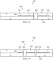
- FIG 8 an illustration of a cross-sectional view of a structure with a filled gap is depicted in accordance with an illustrative embodiment.
- hole 802 has been drilled through first component 502 , structural gap filler 702 , and second component 504 .
- hole 802 has been drilled through injection hole 602 of Figures 6 and 7 .
- structural gap filler 702 reduces burr production during drilling of hole 802 . In some illustrative examples, structural gap filler 702 propels fragments of first component 502 away from structural gap filler 702 during drilling of hole 802 .
- drilling hole 802 removes at least a portion of structural gap filler 702 and at least a portion of encapsulated drilling debris 703 . In some illustrative examples, drilling hole 802 removes burrs on at least one of first component 502 or second component 504 from drilling hole 602 .
- FIG. 9 an illustration of a cross-sectional view of a structure with a filled gap is depicted in accordance with an illustrative embodiment.
- hole 902 has been drilled through first component 502 , structural gap filler 702 , and second component 504 .
- hole 902 has been drilled offset from injection hole 602 .
- Hole 902 and hole 802 of Figure 8 are two implementations for placement of hole 221 of Figure 2 .
- structural gap filler 702 reduces burr production during drilling of hole 902 . In some illustrative examples, structural gap filler 702 propels fragments of first component 502 away from structural gap filler 702 during drilling of hole 902 . In some illustrative examples, drilling hole 802 removes at least a portion of structural gap filler 702 and at least a portion of encapsulated drilling debris 703 .
- Method 1000 can be performed to form a structure of aircraft 100 of Figure 1 .
- Method 1000 can be performed to form structure 202 of Figure 2 .
- Method 1000 can be performed to form structure 300 of Figures 3-4 .
- Method 1000 can be performed in forming structure 500 of Figures 5-9 .
- Method 1000 drills an injection hole through the first component and second component (operation 1002 ).
- Method 1000 encapsulates drilling debris generated between the first component and the second component during drilling of the injection hole by injecting a structural gap filler through the injection hole and between the first component and the second component to form encapsulated drilling debris (operation 1004 ).
- Method 1000 drills a hole through the injection hole and through the first component, the structural gap filler, and the second component (operation 1006 ).
- the hole is drilled concentric through the injection hole.
- the hole is drilled through the injection hole but not concentric with the injection hole.
- the hole occupies the space previously including the injection hole.
- the hole is drilled through the injection hole, the hole encompasses the injection hole.
- Method 1000 maintains clamp-up of the first component and the second component between drilling the injection hole and drilling the hole (operation 1008 ). Afterwards, method 1000 terminates.
- drilling the hole removes at least a portion of the structural gap filler and at least a portion of the encapsulated drilling debris (operation 1010 ).
- the at least a portion of the encapsulated drilling debris includes burrs.
- method 1000 cures the structural gap filler prior to drilling the hole (operation 1012 ).
- the structural gap filler can be cured through any desirable method.
- the structural gap filler is heat cured.
- the structural gap filler is cured by applying heat to the structural gap filler.
- the structural gap filler is cured by leaving the structural gap filler at ambient temperature for a set period of time.
- drilling the hole through the structural gap filler propels fragments of the first component away from the structural gap filler (operation 1014 ). In some illustrative examples, drilling the hole through the structural gap filler reduces burr production during drilling of the hole (operation 1016 ).
- method 1000 positions the first component relative to the second component (operation 1018 ) and clamps up the first component and second component prior to drilling the injection hole (operation 1020 ).
- Method 1100 can be performed to form a structure of aircraft 100 of Figure 1 .
- Method 1100 can be performed to form structure 202 of Figure 2 .
- Method 1100 can be performed to form structure 300 of Figures 3-4 .
- Method 1100 can be performed in forming structure 500 of Figures 5-9 .
- Method 1100 drills an injection hole through a first component and a second component (operation 1102 ).
- Method 1100 encapsulates drilling debris generated between the first component and the second component during drilling of the injection hole by injecting a structural gap filler through the injection hole and between the first component and the second component to form encapsulated drilling debris (operation 1104 ).
- Method 1100 drills a hole through the first component, the structural gap filler, and the second component, the hole offset from the injection hole (operation 1106 ).
- the hole is drilled offset from the injection hole, a portion of the injection hole is encompassed by the hole.
- the injection hole remains in the first component and the second component.
- Method 1100 maintains clamp-up of the first component and the second component between drilling the injection hole and drilling the hole (operation 1108 ). Afterwards, method 1100 terminates.
- method positions the first component relative to the second component (operation 1110 ) and clamping up the first component and second component prior to drilling the injection hole (operation 1112 ). In some illustrative examples, method 1100 cures the structural gap filler prior to drilling the hole (operation 1114 ).
- drilling the hole through the structural gap filler propels fragments of the first component away from the structural gap filler (operation 1116 ). In some illustrative examples, drilling the hole through the structural gap filler reduces burr production during drilling of the hole (operation 1118 ).
- Method 1200 can be performed to form a structure of aircraft 100 of Figure 1 .
- Method 1200 can be performed to form structure 202 of Figure 2 .
- Method 1200 can be performed to form structure 300 of Figures 3-4 .
- Method 1200 can be performed in forming structure 500 of Figures 5-9 .
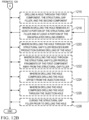
- Method 1200 drills an injection hole through the first component and second component (operation 1202).
- Method 1200 injects a structural gap filler through the injection hole and between the first component and the second component to fill a gap between the first component and the second component (operation 1204 ).
- Method 1200 maintains clamp-up of the first component and the second component between drilling the injection hole and injecting the structural gap filler (operation 1206 ). Afterwards, method 1200 terminates.
- method 1200 further comprises positioning the first component relative to the second component (operation 1208 ). In some illustrative examples, method 1200 clamps up the first component and the second component prior to drilling the injection hole (operation 1210 ).
- injecting the structural gap filler encapsulates drilling debris generated between the first component and the second component during drilling of the injection hole to form encapsulated drilling debris (operation 1212 ). In some illustrative examples, injecting the structural gap filler pushes some drilling debris generated between the first component and the second component during drilling of the injection hole away from the injection hole (operation 1214 ).
- method 1200 drills a hole through the first component, the structural gap filler, and the second component (operation 1216 ).
- drilling the hole removes at least a portion of the structural gap filler and at least a portion of the encapsulated drilling debris (operation 1218 ). In some illustrative examples, drilling the hole through the structural gap filler reduces burr production during drilling of the hole (operation 1220 ). In some illustrative examples, drilling the hole through the structural gap filler propels fragments of the first component away from the structural gap filler (operation 1222 ).
- drilling the hole comprises drilling the hole offset from the injection hole (operation 1224 ). In some illustrative examples, drilling the hole comprises drilling the hole through the injection hole (operation 1226 ). In some illustrative examples, method 1200 cures the structural gap filler prior to drilling the hole (operation 1228 ).
- Method 1300 can be performed to form a structure of aircraft 100 of Figure 1 .
- Method 1300 can be performed to form structure 202 of Figure 2 .
- Method 1300 can be performed to form structure 300 of Figures 3-4 .
- Method 1300 can be performed in forming structure 500 of Figures 5-9 .
- Method 1300 positions the first component relative to the second component (operation 1302 ). Method 1300 clamps up the first component and second component to reduce space between the first component and the second component (operation 1304 ). Method 1300 drills an injection hole through the first component and the second component (operation 1306 ). Method 1300 encapsulates drilling debris generated between the first component and the second component during drilling of the injection hole by injecting a structural gap filler through the injection hole and between the first component and the second component to form encapsulated drilling debris (operation 1308 ). Method 1300 drills a hole through the injection hole and through the first component, the structural gap filler, and the second component, drilling the hole through the structural gap filler reduces burr production during drilling of the hole (operation 1310 ). Method 1300 maintains clamp-up of the first component and the second component between drilling the injection hole and drilling the hole (operation 1312 ). Afterwards, method 1300 terminates.
- drilling the hole comprises drilling the hole offset from the injection hole (operation 1314 ). In some illustrative examples, drilling the hole comprises drilling the hole through the injection hole (operation 1316 ).
- drilling the hole removes at least a portion of the structural gap filler and at least a portion of the encapsulated drilling debris (operation 1318 ).
- method 1300 cures the structural gap filler prior to drilling the hole (operation 1320 ).
- drilling the hole through the structural gap filler reduces burr production during drilling of the hole (operation 1322 ).
- the phrase "at least one of,” when used with a list of items, means different combinations of one or more of the listed items may be used and only one of each item in the list may be needed.
- “at least one of item A, item B, or item C” may include, without limitation, item A, item A and item B, or item B. This example also may include item A, item B, and item C or item B and item C. Of course, any combinations of these items may be present.
- "at least one of” may be, for example, without limitation, two of item A; one of item B; and ten of item C; four of item B and seven of item C; or other suitable combinations.
- the item may be a particular object, thing, or a category. In other words, at least one of means any combination items and number of items may be used from the list but not all of the items in the list are required.
- each block in the flowcharts or block diagrams may represent at least one of a module, a segment, a function, or a portion of an operation or step.
- the function or functions noted in the blocks may occur out of the order noted in the figures. For example, in some cases, two blocks shown in succession may be executed substantially concurrently, or the blocks may sometimes be performed in the reverse order, depending upon the functionality involved. Also, other blocks may be added in addition to the illustrated blocks in a flowchart or block diagram. Some blocks may be optional. For example, any of operation 1212 through operation 1218 may be optional.
- aircraft manufacturing and service method 1400 may be described in the context of aircraft manufacturing and service method 1400 as shown in Figure 14 and aircraft 1500 as shown in Figure 15 .
- Figure 14 an illustration of an aircraft manufacturing and service method in a form of a block diagram is depicted in accordance with an illustrative embodiment.
- aircraft manufacturing and service method 1400 may include specification and design 1402 of aircraft 1500 in Figure 15 and material procurement 1404 .
- aircraft 1500 During production, component and subassembly manufacturing 1406 and system integration 1408 of aircraft 1500 takes place. Thereafter, aircraft 1500 may go through certification and delivery 1410 in order to be placed in service 1412 . While in service 1412 by a customer, aircraft 1500 is scheduled for routine maintenance and service 1414 , which may include modification, reconfiguration, refurbishment, or other maintenance and service.
- Each of the processes of aircraft manufacturing and service method 1400 may be performed or carried out by a system integrator, a third party, and/or an operator.
- the operator may be a customer.
- a system integrator may include, without limitation, any number of aircraft manufacturers and major-system subcontractors
- a third party may include, without limitation, any number of vendors, subcontractors, and suppliers
- an operator may be an airline, a leasing company, a military entity, a service organization, and so on.
- aircraft 1500 is produced by aircraft manufacturing and service method 1400 of Figure 14 and may include airframe 1502 with plurality of systems 1504 and interior 1506 .
- systems 1504 include one or more of propulsion system 1508 , electrical system 1510 , hydraulic system 1512 , and environmental system 1514 . Any number of other systems may be included.
- Apparatuses and methods embodied herein may be employed during at least one of the stages of aircraft manufacturing and service method 1400 .
- One or more illustrative embodiments may be manufactured or used during at least one of component and subassembly manufacturing 1406 , system integration 1408 , in service 1412 , or maintenance and service 1414 of Figure 14 .
- a portion of airframe 1502 of aircraft 1500 can be formed by one of method 1000 , method 1100 , method 1200, or method 1300 . At least one of method 1000 , method 1100 , method 1200 , or method 1300 can be performed during component and subassembly manufacturing 1406 . A composite structure formed using one of method 1000 , method 1100 , method 1200 , or method 1300 can be present and utilized during in service 1412 . At least one of method 1000 , method 1100 , method 1200 , or method 1300 can be performed during maintenance and service 1414 to form a replacement part.
- the illustrative examples provide methods to enable one up assembly for components with gaps between the mating surfaces.
- the illustrative examples can reduce or eliminate the step of taking apart structures (assemblies) and removing burrs within a gap after drilling.
- the illustrative examples can reduce burr generation in assembly gaps.
- the illustrative examples can encapsulate burrs from injection hole drilling operations.
- the illustrative examples reduce manufacturing time by reducing or eliminating disassembly and cleaning steps.
- the illustrative examples enable one up assembly by allowing for fastener insertion after drilling without taking apart structures for cleaning.
- the illustrative examples can enable one up assembly on airplane members with gaps larger than 0.010" where a chip or burr can result from the drilling with a gap between the skin and the substructure.
- a structural gap filler material is injected into a gap present between components, such as aircraft components, through an injection hole.
- the injection hole is a fastener pilot hole.
- Burrs that occur during the injection hole drilling process are encapsulated in the structural gap filler material. Once the structural gap filler is cured, a fastener hole is drilled into the components. The cured structural gap filler material reduces or prevents burrs from developing during the final drilling process as there is not a gap between the components.
- a fastener hole is drilled to size over the injection hole.
- final hole sizing is larger than the injection hole and thus burrs from pilot hole drilling that were encapsulated by structural gap filler can be eliminated (drilled out) when the final hole sizing is completed.
- drill filings encapsulated with liquid shim material injected in the drill (pilot) hole to encapsulate burrs and push drill filings away from hole edge may be removed, at least partially after drying and drilling out to full size.
- an injection nozzle with "O" ring seals seals the nozzle to the hole walls on either side of the gap being sealed. The sealant is injected through the nozzle and past the first "O" ring seal at the gap between the proximal and distal material being fastened. The "O" ring seals can prevent sealant squeezing out of either the proximal or distal end of the fastener hole.
Landscapes
- Engineering & Computer Science (AREA)
- Mechanical Engineering (AREA)
- Manufacturing & Machinery (AREA)
- Transportation (AREA)
- Aviation & Aerospace Engineering (AREA)
- Chemical & Material Sciences (AREA)
- Composite Materials (AREA)
- Life Sciences & Earth Sciences (AREA)
- Forests & Forestry (AREA)
- Drilling And Boring (AREA)
- Connection Of Plates (AREA)
Abstract
Description
- The present disclosure relates generally to structural assembly and more specifically to filling gaps between two components.
- During manufacturing of aircraft, loose debris within an aircraft structure is undesirable. Currently airplane structures are taken apart and burrs or drilling debris are removed from gaps between components after drilling. Cleaning and repositioning the components adds significant flow time and labor to the airplane build process.
- Therefore, it would be desirable to have a method and apparatus that takes into account at least some of the issues discussed above, as well as other possible issues. For example, it would be desirable to have an alternative to taking apart structures and removing loose debris between the structures.
- An embodiment of the present disclosure provides a method of performing one-up assembly of a structure. An injection hole is drilled through the first component and second component. Drilling debris generated between the first component and the second component during drilling of the injection hole are encapsulated by injecting a structural gap filler through the injection hole and between the first component and the second component. A hole is drilled through the injection hole and through the first component, the structural gap filler, and the second component. Clamp-up of the first component and the second component is maintained between drilling the injection hole and drilling the hole.
- An embodiment of the present disclosure provides a method of performing one-up assembly of a structure. An injection hole is drilled through a first component and a second component. Drilling debris generated between the first component and the second component during drilling of the injection hole is encapsulated by injecting a structural gap filler through the injection hole and between the first component and the second component. A hole is drilled through the first component, the structural gap filler, and the second component, the hole offset from the injection hole. Clamp-up of the first component and the second component is maintained between drilling the injection hole and drilling the hole.
- Yet another embodiment of the present disclosure provides a method of performing one-up assembly of a structure. An injection hole is drilled through the first component and second component. A structural gap filler is injected through the injection hole and between the first component and the second component to fill a gap between the first component and the second component. Clamp-up of the first component and the second component is maintained between drilling the injection hole and injecting the structural gap filler.
- A further embodiment of the present disclosure provides a method of performing one-up assembly. A first component is positioned relative to a second component. The first component and the second component are pulled up to reduce space between the first component and the second component. An injection hole is drilled through the first component and the second component. Drilling debris generated between the first component and the second component during drilling of the injection hole are encapsulated by injecting a structural gap filler through the injection hole and between the first component and the second component. A hole is drilled through the injection hole and through the first component, the structural gap filler, and the second component. Drilling the hole through the structural gap filler reduces burr production during drilling of the hole. Clamp-up of the first component and the second component is maintained between drilling the injection hole and drilling the hole.
- The features and functions can be achieved independently in various embodiments of the present disclosure or may be combined in yet other embodiments in which further details can be seen with reference to the following description and drawings.
- The novel features believed characteristic of the illustrative embodiments are set forth in the appended claims. The illustrative embodiments, however, as well as a preferred mode of use, further objectives and features thereof, will best be understood by reference to the following detailed description of an illustrative embodiment of the present disclosure when read in conjunction with the accompanying drawings, wherein:
-
Figure 1 is an illustration of an aircraft in accordance with an illustrative embodiment; -
Figure 2 is an illustration of a block diagram of a manufacturing environment in accordance with an illustrative embodiment; -
Figure 3 is an illustration of a cross-sectional view of a structure with structural gap filler in accordance with an illustrative embodiment; -
Figure 4 is an illustration of a top view of a structure with structural gap filler in accordance with an illustrative embodiment; -
Figure 5 is an illustration of a cross-sectional view of a structure with a gap in accordance with an illustrative embodiment; -
Figure 6 is an illustration of a cross-sectional view of a structure with a gap in accordance with an illustrative embodiment; -
Figure 7 is an illustration of a cross-sectional view of a structure with a filled gap in accordance with an illustrative embodiment; -
Figure 8 is an illustration of a cross-sectional view of a structure with a filled gap in accordance with an illustrative embodiment; -
Figure 9 is an illustration of a cross-sectional view of a structure with a filled gap in accordance with an illustrative embodiment; -
Figure 10 is a flowchart of a method of performing one-up assembly of a structure in accordance with an illustrative embodiment; -
Figure 11 is a flowchart of a method of performing one-up assembly of a structure in accordance with an illustrative embodiment; -
Figures 12A-12B are a flowchart of a method of performing one-up assembly of a structure in accordance with an illustrative embodiment; -
Figure 13 is a flowchart of a method of performing one-up assembly of a structure in accordance with an illustrative embodiment; -
Figure 14 is an illustration of an aircraft manufacturing and service method in a form of a block diagram in accordance with an illustrative embodiment; and -
Figure 15 is an illustration of an aircraft in a form of a block diagram in which an illustrative embodiment may be implemented. - The illustrative examples recognize and take into account one or more different considerations. The illustrative examples recognize and take into account that currently it is desirable for two drilled surfaces in aircraft manufacturing to be pulled together less than 0.008". The illustrative examples recognize and take into account that it is desirable to reduce the manufacturing time of components. The illustrative examples recognize and take into account that reducing manufacturing steps can also reduce manufacturing cost.
- The illustrative examples recognize and take into account that composite materials include reinforcing fibers bound in resin matrix. The fibers can be unidirectional or can take the form of a woven cloth or fabric. The fibers and resins are arranged and cured or consolidated to form a composite material. The illustrative examples recognize and take into account that composite materials are not as flexible as metals without fracture.
- Turning now to
Figure 1 , an illustration of an aircraft is depicted in accordance with an illustrative embodiment.Aircraft 100 haswing 102 andwing 104 attached tobody 106.Aircraft 100 includesengine 108 attached towing 102 andengine 110 attached towing 104. -
Body 106 hastail section 112.Horizontal stabilizer 114,horizontal stabilizer 116, andvertical stabilizer 118 are attached totail section 112 ofbody 106. -
Aircraft 100 is an example of an aircraft having large composite components that can be manufactured using structural gap filler and methods of use. For example, portions ofbody 106,wing 102, orwing 104 can be manufactured using the illustrative examples of a structural gap filler and methods of one-up assembly. - Turning now to
Figure 2 , an illustration of a block diagram of a manufacturing environment is depicted in which an illustrative embodiment may be implemented.Manufacturing environment 200 is a manufacturing environment in whichstructure 202 can be assembled using one-up assembly. -
Structure 202 comprisesfirst component 204,second component 206. When pulled up,gap 208 is present betweenfirst component 204 andsecond component 206. Drilling throughfirst component 204,gap 208, andsecond component 206 generates drilling debris. -
Injection hole 209 is drilled throughfirst component 204,gap 208, andsecond component 206 generatingdrilling debris 210 withingap 208.Drilling debris 210 includes at least one of loose foreign object debris or burrs 211. -
Structural gap filler 212 is injected throughinjection hole 209 to fillgap 208. As depicted,structural gap filler 212 encapsulatesdrilling debris 210 betweenfirst component 204 andsecond component 206.Structural gap filler 212 hascompressive strength 214 equivalent to or greater thancompressive strength 216 of joint 218 betweenfirst component 204 andsecond component 206. -
Structural gap filler 212 can include at least one of a curable structural gap filler material, a hardening structural gap filler material, a resin, an epoxy, an epoxy resin, a two-part resin, an adhesive, an adhesive resin, a polymer, a polymeric material, or a curable composite material.Structural gap filler 212 is configured to be in a liquid or flowable state whenstructural gap filler 212 is withininjector 219 and injected intogap 208.Structural gap filler 212 is configured to cure, harden, solidify, and/or set into a structural material after being injected byinjector 219.Injector 219 is configured to inject any suitable type ofstructural gap filler 212. In some illustrative examples,structural gap filler 212 may be referred to as a liquid shim material, or as a structural liquid shim material. -
Structural gap filler 212 hasmaterial properties 220 selected to encapsulatedrilling debris 210.Structural gap filler 212 hasmaterial properties 220 selected to form joint 218. In some illustrative examples,structural gap filler 212 hascompressive strength 214 of at least 30 ksi. In some illustrative examples,structural gap filler 212 has acompressive strength 214 of at least 60 ksi. - By encapsulating
drilling debris 210, manufacturing steps are reduced forstructure 202. By encapsulatingdrilling debris 210,drilling debris 210 remain withinstructure 202. By encapsulatingdrilling debris 210,first component 204 andsecond component 206 are not separated to removedrilling debris 210. By encapsulatingdrilling debris 210, clamp-up offirst component 204 andsecond component 206 is maintained through later processing steps. Encapsulatingdrilling debris 210 eliminates cleaning steps that take apartfirst component 204 andsecond component 206. Encapsulatingdrilling debris 210 saves manufacturing time and reduces manufacturing costs. -
Structure 202 also compriseshole 221 drilled throughfirst component 204,structural gap filler 212, andsecond component 206. Althoughhole 221 is depicted as separate frominjection hole 209, in some illustrative examples,hole 221 is drilled throughinjection hole 209. In these illustrative examples,hole 221 has a greater diameter thaninjection hole 209 andinjection hole 209 is drilled out bydrilling hole 221. In some illustrative examples,hole 221 andinjection hole 209 are concentric. - In some illustrative examples,
drilling hole 221 removes at least a portion of thestructural gap filler 212 and at least a portion ofdrilling debris 210 encapsulated bystructural gap filler 212. When drillingdebris 210 are encapsulated bystructural gap filler 212,drilling debris 210 can be referred to as encapsulated drilling debris. In some illustrative examples, drilling hole removesburrs 211 of at least one offirst component 204 orsecond component 206 formed bydrilling injection hole 209. - In some illustrative examples,
drilling hole 221 comprisesdrilling hole 221 offset frominjection hole 209. In some of these illustrative examples,drilling hole 221 removesstructural gap filler 212 anddrilling debris 210. In some illustrative examples, whenhole 221 is drilled offset frominjection hole 209,hole 221 is drilled offset from a center ofinjection hole 209. In some illustrative examples, whenhole 221 is drilled offset frominjection hole 209,hole 221 is drilled such thathole 221 is not concentric withinjection hole 209. In some illustrative examples, whenhole 221 is drilled offset frominjection hole 209, a portion ofinjection hole 209 is encompassed byhole 221. In some illustrative examples, whenhole 221 is drilled offset frominjection hole 209,injection hole 209 remains infirst component 204 andsecond component 206. - In some illustrative examples,
structural gap filler 212 propelsfragments 222 offirst component 204 away fromstructural gap filler 212 during drilling ofhole 221. In some illustrative examples,structural gap filler 212 reducesburr production 224 during drilling ofhole 221. In some illustrative examples,structural gap filler 212 reducesburr production 224 by fillinggap 208. - In some illustrative examples,
first component 204 is formed of at least one ofcomposite 226 ormetal 228. In some illustrative examples,second component 206 is formed of at least one ofcomposite 230 ormetal 232. In some illustrative examples, at least one offirst component 204 orsecond component 206 is formed of a composite material, composite 226 orcomposite 230. - In some illustrative examples, at least one of
first component 204 orsecond component 206 comprises metal,metal 228 ormetal 232. In some illustrative examples,first component 204 andsecond component 206 are parts ofaircraft 234. In these illustrative examples,first component 204 andsecond component 206 are aircraft components. -
Structural gap filler 212 is selected to be compatible with the material offirst component 204 andsecond component 206.Structural gap filler 212 is selected such thatstructural gap filler 212 does not undesirably chemically react with the material offirst component 204 andsecond component 206. -
Structural gap filler 212 hasmaterial properties 220 configured to allow for injection byinjector 219.Structural gap filler 212 hasmaterial properties 220 configured to encapsulatedrilling debris 210. In some illustrative examples,material properties 220 includeshrinkage 236 configured to continue to fillgap 208 after curingstructural gap filler 212. In some illustrative examples,material properties 220 include shear thinning 238 configured to encapsulatedrilling debris 210. Shear thinning 238 is configured to enablestructural gap filler 212 to flow intogap 208 when energy, such as pressure from injection, is applied tostructural gap filler 212. Once injection pressure is removed fromstructural gap filler 212, shear thinning 238 ofstructural gap filler 212 maintainsstructural gap filler 212 withingap 208. In some illustrative examples, shear thinning 238 ofstructural gap filler 212 substantially stops movement ofstructural gap filler 212 such thatstructural gap filler 212 does not flow outside ofgap 208. -
Material properties 220 ofstructural gap filler 212 are configured to provide encapsulation ofdrilling debris 210. In some illustrative examples, the viscosity measurement range at room temperature (75F) can be from 300K Poise at 1 rad/s to 6K Poise at 100 rad/s. Thixotropic Index is a test for shear thinning materials. The Thixotropic Index measures the material viscosity at a slow rotation speed and divides the result by the viscosity at a higher rotation speed that is typically a factor of 10 higher from the slower speed rotation. For Thixotropic Indexes, higher numbers indicate a greater amount of shear thinning. In some illustrative examples,structural gap filler 212 can have Thixotropic Indexes of approximately 4 to approximately 8. - In some illustrative examples,
structural gap filler 212 hascompressive strength 214 equal to or greater than at least one ofcompressive strength 242 offirst component 204 orcompressive strength 244 ofsecond component 206.Gap 208 is present betweenfirst surface 246 offirst component 204 andsecond surface 248 andsecond component 206. In some illustrative examples,first component 204 andsecond component 206 are components offuselage 250 ofaircraft 234. In some illustrative examples,first component 204 andsecond component 206 are components ofwing 252.Structural gap filler 212 is configured to meetstructural loading 254 of joint 218 dependent on location and functioning ofjoint 218.Material properties 220 ofstructural gap filler 212 withinwing 252 could be different than material properties ofstructural gap filler 212 withinfuselage 250 due to differentstructural loading 254 ofwing 252 andfuselage 250. In some illustrative examples, joint 218 is infuel tank 256 withinwing 252. In some illustrative examples, when joint 218 is infuel tank 256,structural gap filler 212 is configured to reduce or preventleaks 258 fromfuel tank 256. In these illustrative examples,material properties 220 ofstructural gap filler 212 are also selected to reduce or prevent leaks. - In some illustrative examples,
first component 204 comprisesskin 260. Whenfirst component 204 comprisesskin 260,gap 208 is part of inaccessible portions ofstructure 202. In some illustrative examples,skin 260 is part of one offuselage 250 orwing 252. - In some illustrative examples,
injection hole 209 is a pilot hole. In some illustrative examples,hole 221 is configured to receivefastener 262 to joinfirst component 204 andsecond component 206. - In some illustrative examples,
gap 208 is identified usinginspector 264. In some illustrative examples,inspector 264 comprisescamera 266.Camera 266 can be inserted intoinjection hole 209 to detectgap 208. In some illustrative examples,inspector 264 comprisesultrasonic inspector 268. In some illustrative examples,gap 208 is detected usingultrasonic inspector 268. - The illustration of
manufacturing environment 200 inFigure 2 is not meant to imply physical or architectural limitations to the manner in which an illustrative embodiment may be implemented. Other components in addition to or in place of the ones illustrated may be used. Some components may be unnecessary. Also, the blocks are presented to illustrate some functional components. One or more of these blocks may be combined, divided, or combined and divided into different blocks when implemented in an illustrative embodiment. - For example, although only one
injection hole 209 is depicted, any desirable quantity of injection holes can be drilled intofirst component 204 andsecond component 206. In some illustrative examples, multiple injection holes can be drilled throughfirst component 204,gap 208, andsecond component 206. In some of these illustrative examples,structural gap filler 212 is injected through multiple injection holes intogap 208. - Turning now to
Figure 3 is an illustration of a cross-sectional view of a structure with structural gap filler is depicted in accordance with an illustrative embodiment.Structure 300 is a physical implementation ofstructure 202 ofFigure 2 .Structure 300 comprisesfirst component 302 andsecond component 304 joined together byfasteners 306.First component 302 is a physical implementation offirst component 204 ofFigure 2 .Second component 304 is a physical implementation ofsecond component 206 ofFigure 2 . As depicted,fasteners 306 comprisefastener 308,fastener 310,fastener 312, andfastener 314.Fasteners 306 extend throughholes 316 includinghole 318,hole 320,hole 322, andhole 324. -
Injection hole 326 andinjection hole 328 were drilled throughfirst component 302 andsecond component 304. Prior todrilling injection hole 326 andinjection hole 328,first component 302 andsecond component 304 were pulled up for performing manufacturing processes. As can be seen inview 330, after clamping upfirst component 302 andsecond component 304,gap 332 andgap 334 were present betweenfirst component 302 andsecond component 304. -
Gap 332 andgap 334 are outside of manufacturing tolerances. In some illustrative examples, gaps greater than 0.008" are outside of manufacturing tolerances.Structural gap filler 336 is present ingap 332 to bringgap 332 within tolerance.Structural gap filler 338 is present ingap 334 to bringgap 334 within tolerance. - In
view 330,structural gap filler 336 ingap 332 andstructural gap filler 338 ingap 334 are visible.Structural gap filler 336 encapsulates drilling debris (not visible) fromdrilling injection hole 326.Structural gap filler 336 is injected throughinjection hole 326 prior todrilling hole 318 andhole 320.Hole 318 andhole 320 are drilled throughfirst component 302,structural gap filler 338, andsecond component 304. - In some illustrative examples,
structural gap filler 336 reduces burr production during drilling ofhole 318 andhole 320. In some illustrative examples,structural gap filler 336 propels fragments offirst component 302 away fromstructural gap filler 336 during drilling ofhole 318 andhole 320. -
Structural gap filler 338 encapsulates drilling debris (not visible) fromdrilling injection hole 328.Structural gap filler 338 is injected throughinjection hole 328 prior todrilling hole 322 andhole 324. In some illustrative examples,structural gap filler 338 reduces burr production during drilling ofhole 322 andhole 324. In some illustrative examples,structural gap filler 338 propels fragments offirst component 302 away fromstructural gap filler 338 during drilling ofhole 322 andhole 324. - In some illustrative examples,
structural gap filler 336 andstructural gap filler 338 are the same material. In some illustrative examples,structural gap filler 336 andstructural gap filler 338 are different materials.Structural gap filler 336 andstructural gap filler 338 are present in joint 340 betweenfirst component 302 andsecond component 304. -
Structural gap filler 336 andstructural gap filler 338 each have a compressive strength equivalent to or greater than a compressive strength of joint 340 betweenfirst component 302 andsecond component 304.Structural gap filler 336 andstructural gap filler 338 have material properties configured to provide encapsulation of the drilling debris. For example,structural gap filler 336 andstructural gap filler 338 have shear thinning and fixotropic characteristics configured to encapsulate the drilling debris (not depicted). - Turning now to
Figure 4 , an illustration of a top view of a structure with structural gap filler is depicted in accordance with an illustrative embodiment. Inview 400, extents ofstructural gap filler 336 andstructural gap filler 338 are illustrated. Inview 400hole 318 andhole 320 extend throughstructural gap filler 336. Inview 400hole 322 andhole 324 extend throughstructural gap filler 338.Structural gap filler 336 andstructural gap filler 338reduce gap 332 andgap 334 respectively to within tolerance. - In some illustrative examples, at least one of
hole 318,hole 320,hole 322, orhole 324 can extend throughfirst component 302 and second component 304 (not visible) without a structural gap filler. When a gap is not present, a hole can be drilled throughfirst component 302 andsecond component 304 without a structural gap filler. When a gap betweenfirst component 302 andsecond component 304 is within tolerance, a hole can be drilled throughfirst component 302 andsecond component 304 without a structural gap filler. Any combination of holes with and without structural gap filler can be present instructure 300. - Turning now to
Figure 5 , an illustration of a cross-sectional view of a structure with a gap in accordance with an illustrative embodiment.Structure 500 is a physical implementation ofstructure 202 ofFigure 2 .Structure 500 comprisesfirst component 502 andsecond component 504 pulled up to receive drilling operations.First component 502 is a physical implementation offirst component 204 ofFigure 2 .Second component 504 is a physical implementation ofsecond component 206 ofFigure 2 .Gap 506 is present betweenfirst component 502 andsecond component 504.Gap 506 is an out of tolerance gap. Due to presence ofgap 506, drilling debris will be generated betweenfirst component 502 andsecond component 504 during drilling. - Turning now to
Figure 6 , an illustration of a cross-sectional view of a structure with a gap is depicted in accordance with an illustrative embodiment. Inview 600injection hole 602 has been drilled throughfirst component 502 andsecond component 504. Indrilling injection hole 602,drilling debris 604 were generated withingap 506.Drilling debris 604 includes at least one of loose foreign object debris or burrs. - Turning now to
Figure 7 , an illustration of a cross-sectional view of a structure with a filled gap is depicted in accordance with an illustrative embodiment. Inview 700structural gap filler 702 has been injected intoinjection hole 602.Structural gap filler 702fills gap 506.Structural gap filler 702 encapsulatesdrilling debris 604 betweenfirst component 502 andsecond component 504.Drilling debris 604 encapsulated bystructural gap filler 702 can be referred to as encapsulateddrilling debris 703. By encapsulatingdrilling debris 604,structural gap filler 702 can reduce the number of cleaning or debris removal steps. By encapsulatingdrilling debris 604 instructural gap filler 702,drilling debris 604 do not undesirably affectfirst component 502 orsecond component 504. Use ofstructural gap filler 702 to encapsulatedrilling debris 604 can reduce at least one of manufacturing time or manufacturing cost. By encapsulatingdrilling debris 604, clamp-up offirst component 502 and thesecond component 504 is maintained betweendrilling injection hole 602 and subsequent steps. In some illustrative examples, by encapsulatingdrilling debris 604, taking apartfirst component 502 andsecond component 504 and cleaning out burrs or drilling debris is eliminated. - Turning now to
Figure 8 , an illustration of a cross-sectional view of a structure with a filled gap is depicted in accordance with an illustrative embodiment. Inview 800hole 802 has been drilled throughfirst component 502,structural gap filler 702, andsecond component 504. In this illustrative example,hole 802 has been drilled throughinjection hole 602 ofFigures 6 and 7 . - In some illustrative examples,
structural gap filler 702 reduces burr production during drilling ofhole 802. In some illustrative examples,structural gap filler 702 propels fragments offirst component 502 away fromstructural gap filler 702 during drilling ofhole 802. - In some illustrative examples,
drilling hole 802 removes at least a portion ofstructural gap filler 702 and at least a portion of encapsulateddrilling debris 703. In some illustrative examples,drilling hole 802 removes burrs on at least one offirst component 502 orsecond component 504 fromdrilling hole 602. - Turning now to
Figure 9 , an illustration of a cross-sectional view of a structure with a filled gap is depicted in accordance with an illustrative embodiment. Inview 900hole 902 has been drilled throughfirst component 502,structural gap filler 702, andsecond component 504. In this illustrative example,hole 902 has been drilled offset frominjection hole 602.Hole 902 andhole 802 ofFigure 8 are two implementations for placement ofhole 221 ofFigure 2 . - In some illustrative examples,
structural gap filler 702 reduces burr production during drilling ofhole 902. In some illustrative examples,structural gap filler 702 propels fragments offirst component 502 away fromstructural gap filler 702 during drilling ofhole 902. In some illustrative examples,drilling hole 802 removes at least a portion ofstructural gap filler 702 and at least a portion of encapsulateddrilling debris 703. - Turning now to
Figure 10 , a flowchart of a method of performing one-up assembly of a structure is depicted in accordance with an illustrative embodiment.Method 1000 can be performed to form a structure ofaircraft 100 ofFigure 1 .Method 1000 can be performed to formstructure 202 ofFigure 2 .Method 1000 can be performed to formstructure 300 ofFigures 3-4 .Method 1000 can be performed in formingstructure 500 ofFigures 5-9 . -
Method 1000 drills an injection hole through the first component and second component (operation 1002).Method 1000 encapsulates drilling debris generated between the first component and the second component during drilling of the injection hole by injecting a structural gap filler through the injection hole and between the first component and the second component to form encapsulated drilling debris (operation 1004).Method 1000 drills a hole through the injection hole and through the first component, the structural gap filler, and the second component (operation 1006). In some illustrative examples, the hole is drilled concentric through the injection hole. In some other illustrative examples, the hole is drilled through the injection hole but not concentric with the injection hole. When the hole is drilled through the injection hole, the hole occupies the space previously including the injection hole. When the hole is drilled through the injection hole, the hole encompasses the injection hole.Method 1000 maintains clamp-up of the first component and the second component between drilling the injection hole and drilling the hole (operation 1008). Afterwards,method 1000 terminates. - In some illustrative examples, drilling the hole removes at least a portion of the structural gap filler and at least a portion of the encapsulated drilling debris (operation 1010). In some illustrative examples, the at least a portion of the encapsulated drilling debris includes burrs.
- In some illustrative examples,
method 1000 cures the structural gap filler prior to drilling the hole (operation 1012). The structural gap filler can be cured through any desirable method. In some illustrative examples, the structural gap filler is heat cured. In some illustrative examples, the structural gap filler is cured by applying heat to the structural gap filler. In some illustrative examples, the structural gap filler is cured by leaving the structural gap filler at ambient temperature for a set period of time. - In some illustrative examples, drilling the hole through the structural gap filler propels fragments of the first component away from the structural gap filler (operation 1014). In some illustrative examples, drilling the hole through the structural gap filler reduces burr production during drilling of the hole (operation 1016).
- In some illustrative examples,
method 1000 positions the first component relative to the second component (operation 1018) and clamps up the first component and second component prior to drilling the injection hole (operation 1020). - Turning now to
Figure 11 , a flowchart of a method of performing one-up assembly of a structure is depicted in accordance with an illustrative embodiment.Method 1100 can be performed to form a structure ofaircraft 100 ofFigure 1 .Method 1100 can be performed to formstructure 202 ofFigure 2 .Method 1100 can be performed to formstructure 300 ofFigures 3-4 .Method 1100 can be performed in formingstructure 500 ofFigures 5-9 . -
Method 1100 drills an injection hole through a first component and a second component (operation 1102).Method 1100 encapsulates drilling debris generated between the first component and the second component during drilling of the injection hole by injecting a structural gap filler through the injection hole and between the first component and the second component to form encapsulated drilling debris (operation 1104).Method 1100 drills a hole through the first component, the structural gap filler, and the second component, the hole offset from the injection hole (operation 1106). In some illustrative examples, when the hole is drilled offset from the injection hole, a portion of the injection hole is encompassed by the hole. In some illustrative examples, when the hole is drilled offset from injection hole, the injection hole remains in the first component and the second component. -
Method 1100 maintains clamp-up of the first component and the second component between drilling the injection hole and drilling the hole (operation 1108). Afterwards,method 1100 terminates. - In some illustrative examples, method positions the first component relative to the second component (operation 1110) and clamping up the first component and second component prior to drilling the injection hole (operation 1112). In some illustrative examples,
method 1100 cures the structural gap filler prior to drilling the hole (operation 1114). - In some illustrative examples, drilling the hole through the structural gap filler propels fragments of the first component away from the structural gap filler (operation 1116). In some illustrative examples, drilling the hole through the structural gap filler reduces burr production during drilling of the hole (operation 1118).
- Turning now to
Figures 12A-12B , a flowchart of a method of performing one-up assembly of a structure is depicted in accordance with an illustrative embodiment.Method 1200 can be performed to form a structure ofaircraft 100 ofFigure 1 .Method 1200 can be performed to formstructure 202 ofFigure 2 .Method 1200 can be performed to formstructure 300 ofFigures 3-4 .Method 1200 can be performed in formingstructure 500 ofFigures 5-9 . -
Method 1200 drills an injection hole through the first component and second component (operation 1202).Method 1200 injects a structural gap filler through the injection hole and between the first component and the second component to fill a gap between the first component and the second component (operation 1204).Method 1200 maintains clamp-up of the first component and the second component between drilling the injection hole and injecting the structural gap filler (operation 1206). Afterwards,method 1200 terminates. - In some illustrative examples,
method 1200 further comprises positioning the first component relative to the second component (operation 1208). In some illustrative examples,method 1200 clamps up the first component and the second component prior to drilling the injection hole (operation 1210). - In some illustrative examples, injecting the structural gap filler encapsulates drilling debris generated between the first component and the second component during drilling of the injection hole to form encapsulated drilling debris (operation 1212). In some illustrative examples, injecting the structural gap filler pushes some drilling debris generated between the first component and the second component during drilling of the injection hole away from the injection hole (operation 1214).
- In some illustrative examples,
method 1200 drills a hole through the first component, the structural gap filler, and the second component (operation 1216). - In some illustrative examples, drilling the hole removes at least a portion of the structural gap filler and at least a portion of the encapsulated drilling debris (operation 1218). In some illustrative examples, drilling the hole through the structural gap filler reduces burr production during drilling of the hole (operation 1220). In some illustrative examples, drilling the hole through the structural gap filler propels fragments of the first component away from the structural gap filler (operation 1222).
- In some illustrative examples, drilling the hole comprises drilling the hole offset from the injection hole (operation 1224). In some illustrative examples, drilling the hole comprises drilling the hole through the injection hole (operation 1226). In some illustrative examples,
method 1200 cures the structural gap filler prior to drilling the hole (operation 1228). - Turning now to
Figure 13 , a flowchart of a method of performing one-up assembly of a structure is depicted in accordance with an illustrative embodiment.Method 1300 can be performed to form a structure ofaircraft 100 ofFigure 1 .Method 1300 can be performed to formstructure 202 ofFigure 2 .Method 1300 can be performed to formstructure 300 ofFigures 3-4 .Method 1300 can be performed in formingstructure 500 ofFigures 5-9 . -
Method 1300 positions the first component relative to the second component (operation 1302).Method 1300 clamps up the first component and second component to reduce space between the first component and the second component (operation 1304).Method 1300 drills an injection hole through the first component and the second component (operation 1306).Method 1300 encapsulates drilling debris generated between the first component and the second component during drilling of the injection hole by injecting a structural gap filler through the injection hole and between the first component and the second component to form encapsulated drilling debris (operation 1308).Method 1300 drills a hole through the injection hole and through the first component, the structural gap filler, and the second component, drilling the hole through the structural gap filler reduces burr production during drilling of the hole (operation 1310).Method 1300 maintains clamp-up of the first component and the second component between drilling the injection hole and drilling the hole (operation 1312). Afterwards,method 1300 terminates. - In some illustrative examples, drilling the hole comprises drilling the hole offset from the injection hole (operation 1314). In some illustrative examples, drilling the hole comprises drilling the hole through the injection hole (operation 1316).
- In some illustrative examples, drilling the hole removes at least a portion of the structural gap filler and at least a portion of the encapsulated drilling debris (operation 1318). In some illustrative examples,
method 1300 cures the structural gap filler prior to drilling the hole (operation 1320). In some illustrative examples, drilling the hole through the structural gap filler reduces burr production during drilling of the hole (operation 1322). - As used herein, the phrase "at least one of," when used with a list of items, means different combinations of one or more of the listed items may be used and only one of each item in the list may be needed. For example, "at least one of item A, item B, or item C" may include, without limitation, item A, item A and item B, or item B. This example also may include item A, item B, and item C or item B and item C. Of course, any combinations of these items may be present. In other examples, "at least one of" may be, for example, without limitation, two of item A; one of item B; and ten of item C; four of item B and seven of item C; or other suitable combinations. The item may be a particular object, thing, or a category. In other words, at least one of means any combination items and number of items may be used from the list but not all of the items in the list are required.
- The flowcharts and block diagrams in the different depicted embodiments illustrate the architecture, functionality, and operation of some possible implementations of apparatuses and methods in an illustrative embodiment. In this regard, each block in the flowcharts or block diagrams may represent at least one of a module, a segment, a function, or a portion of an operation or step.
- In some alternative implementations of an illustrative embodiment, the function or functions noted in the blocks may occur out of the order noted in the figures. For example, in some cases, two blocks shown in succession may be executed substantially concurrently, or the blocks may sometimes be performed in the reverse order, depending upon the functionality involved. Also, other blocks may be added in addition to the illustrated blocks in a flowchart or block diagram. Some blocks may be optional. For example, any of
operation 1212 throughoperation 1218 may be optional. - Illustrative embodiments of the present disclosure may be described in the context of aircraft manufacturing and
service method 1400 as shown inFigure 14 andaircraft 1500 as shown inFigure 15 . Turning first toFigure 14 , an illustration of an aircraft manufacturing and service method in a form of a block diagram is depicted in accordance with an illustrative embodiment. During pre-production, aircraft manufacturing andservice method 1400 may include specification anddesign 1402 ofaircraft 1500 inFigure 15 andmaterial procurement 1404. - During production, component and
subassembly manufacturing 1406 andsystem integration 1408 ofaircraft 1500 takes place. Thereafter,aircraft 1500 may go through certification anddelivery 1410 in order to be placed inservice 1412. While inservice 1412 by a customer,aircraft 1500 is scheduled for routine maintenance andservice 1414, which may include modification, reconfiguration, refurbishment, or other maintenance and service. - Each of the processes of aircraft manufacturing and
service method 1400 may be performed or carried out by a system integrator, a third party, and/or an operator. In these examples, the operator may be a customer. For the purposes of this description, a system integrator may include, without limitation, any number of aircraft manufacturers and major-system subcontractors; a third party may include, without limitation, any number of vendors, subcontractors, and suppliers; and an operator may be an airline, a leasing company, a military entity, a service organization, and so on. - With reference now to
Figure 15 , an illustration of an aircraft in a form of a block diagram is depicted in which an illustrative embodiment may be implemented. In this example,aircraft 1500 is produced by aircraft manufacturing andservice method 1400 ofFigure 14 and may includeairframe 1502 with plurality ofsystems 1504 and interior 1506. Examples ofsystems 1504 include one or more ofpropulsion system 1508,electrical system 1510,hydraulic system 1512, andenvironmental system 1514. Any number of other systems may be included. - Apparatuses and methods embodied herein may be employed during at least one of the stages of aircraft manufacturing and
service method 1400. One or more illustrative embodiments may be manufactured or used during at least one of component andsubassembly manufacturing 1406,system integration 1408, inservice 1412, or maintenance andservice 1414 ofFigure 14 . - A portion of
airframe 1502 ofaircraft 1500 can be formed by one ofmethod 1000,method 1100,method 1200, ormethod 1300. At least one ofmethod 1000,method 1100,method 1200, ormethod 1300 can be performed during component andsubassembly manufacturing 1406. A composite structure formed using one ofmethod 1000,method 1100,method 1200, ormethod 1300 can be present and utilized during inservice 1412. At least one ofmethod 1000,method 1100,method 1200, ormethod 1300 can be performed during maintenance andservice 1414 to form a replacement part. - The illustrative examples provide methods to enable one up assembly for components with gaps between the mating surfaces. The illustrative examples can reduce or eliminate the step of taking apart structures (assemblies) and removing burrs within a gap after drilling. The illustrative examples can reduce burr generation in assembly gaps. The illustrative examples can encapsulate burrs from injection hole drilling operations. The illustrative examples reduce manufacturing time by reducing or eliminating disassembly and cleaning steps.
- The illustrative examples enable one up assembly by allowing for fastener insertion after drilling without taking apart structures for cleaning. The illustrative examples can enable one up assembly on airplane members with gaps larger than 0.010" where a chip or burr can result from the drilling with a gap between the skin and the substructure.
- A structural gap filler material is injected into a gap present between components, such as aircraft components, through an injection hole. In some illustrative examples, the injection hole is a fastener pilot hole.
- Burrs that occur during the injection hole drilling process are encapsulated in the structural gap filler material. Once the structural gap filler is cured, a fastener hole is drilled into the components. The cured structural gap filler material reduces or prevents burrs from developing during the final drilling process as there is not a gap between the components.
- In some illustrative examples, a fastener hole is drilled to size over the injection hole. In these illustrative examples, final hole sizing is larger than the injection hole and thus burrs from pilot hole drilling that were encapsulated by structural gap filler can be eliminated (drilled out) when the final hole sizing is completed.
- In some of the illustrative examples, drill filings encapsulated with liquid shim material injected in the drill (pilot) hole to encapsulate burrs and push drill filings away from hole edge may be removed, at least partially after drying and drilling out to full size. In some of the illustrative examples, an injection nozzle with "O" ring seals seals the nozzle to the hole walls on either side of the gap being sealed. The sealant is injected through the nozzle and past the first "O" ring seal at the gap between the proximal and distal material being fastened. The "O" ring seals can prevent sealant squeezing out of either the proximal or distal end of the fastener hole.
- Further, the current disclosure comprises embodiments according to the following clauses:
-
Clause 1. A method of assembling a structure, the method comprising:- drilling an injection hole through a first component and a second component;
- encapsulating drilling debris generated between the first component and the second component during drilling of the injection hole by injecting a structural gap filler through the injection hole and between the first component and the second component to form encapsulated drilling debris;
- drilling a hole through the injection hole and through the first component, the structural gap filler, and the second component; and
- maintaining clamp-up of the first component and the second component between drilling the injection hole and drilling the hole.
- Clause 2. The method of
clause 1, wherein drilling the hole removes at least a portion of the structural gap filler and at least a portion of the encapsulated drilling debris. - Clause 3. The method of
clause 1 or 2, further comprising:
curing the structural gap filler prior to drilling the hole. - Clause 4. The method of any of
clauses 1 to 3, wherein drilling the hole through the structural gap filler reduces burr production during drilling of the hole. - Clause 5. The method of any of
clauses 1 to 4, wherein drilling the hole through the structural gap filler propels fragments of the first component away from the structural gap filler. - Clause 6. The method of any of
clauses 1 to 5, further comprising:- positioning the first component relative to the second component; and
- clamping up the first component and second component prior to drilling the injection hole.
-
Clause 7. A method of assembling a structure, the method comprising:- drilling an injection hole through a first component and a second component;
- encapsulating drilling debris generated between the first component and the second component during drilling of the injection hole by injecting a structural gap filler through the injection hole and between the first component and the second component to form encapsulated drilling debris;
- drilling a hole through the first component, the structural gap filler, and the second component, the hole offset from the injection hole; and
- maintaining clamp-up of the first component and the second component between drilling the injection hole and drilling the hole.
- Clause 8. The method of
clause 7, further comprising:
curing the structural gap filler prior to drilling the hole. - Clause 9. The method of
clause 7 or 8, wherein drilling the hole through the structural gap filler reduces burr production during drilling of the hole. - Clause 10. The method of any of
clauses 7 to 9, wherein drilling the hole through the structural gap filler propels fragments of the first component away from the structural gap filler. - Clause 11. The method of any of
clauses 7 to 10, further comprising:- positioning the first component relative to the second component; and
- clamping up the first component and second component prior to drilling the injection hole.
- Clause 12. A method of assembling a structure, the method comprising:
- drilling an injection hole through a first component and a second component;
- injecting a structural gap filler through the injection hole and between the first component and the second component to fill a gap between the first component and the second component; and
- maintaining clamp-up of the first component and the second component between drilling the injection hole and injecting the structural gap filler.
- Clause 13. The method of clause 12, wherein injecting the structural gap filler encapsulates drilling debris generated between the first component and the second component during drilling of the injection hole to form encapsulated drilling debris.
- Clause 14. The method of clause 13, further comprises:
- drilling a hole through the first component, the structural gap filler, and the second component.
- Clause 15. The method of clause 14, wherein drilling the hole removes at least a portion of the structural gap filler and at least a portion of the encapsulated drilling debris.
- Clause 16. The method of clause 14 or 15, further comprising:
curing the structural gap filler prior to drilling the hole. - Clause 17. The method of any of clauses 14 to 16, wherein drilling the hole through the structural gap filler reduces burr production during drilling of the hole.
- Clause 18. The method of any of clauses 14 to 17, wherein drilling the hole through the structural gap filler propels fragments of the first component away from the structural gap filler.
- Clause 19. The method of any of clauses 12 to 18, further comprising:
- positioning the first component relative to the second component; and
- clamping up the first component and second component prior to drilling the injection hole.
- Clause 20. The method of any of clauses 12 to 19, wherein injecting the structural gap filler pushes some drilling debris generated between the first component and the second component during drilling of the injection hole away from the injection hole.
- Clause 21. A method of assembling a structure, the method comprising:
- positioning a first component relative to a second component;
- clamping up the first component and the second component to reduce space between the first component and the second component;
- drilling an injection hole through the first component and the second component;
- encapsulating drilling debris generated between the first component and the second component during drilling of the injection hole by injecting a structural gap filler through the injection hole and between the first component and the second component to form encapsulated drilling debris;
- drilling a hole through the injection hole and through the first component, the structural gap filler, and the second component, drilling the hole through the structural gap filler reduces burr production during drilling of the hole; and
- maintaining clamp-up of the first component and the second component between drilling the injection hole and drilling the hole.
- Clause 22. The method of clause 21, wherein drilling the hole comprises drilling the hole offset from the injection hole.
- Clause 23. The method of clause 21, wherein drilling the hole comprises drilling the hole through the injection hole.
- Clause 24. The method of clause 22, wherein drilling hole removes at least a portion of the structural gap filler and at least a portion of the encapsulated drilling debris.
- Clause 25. The method of any of clauses 21 to 24, further comprising:
curing the structural gap filler prior to drilling the hole. - Clause 26. The method of any of clauses 21 to 25, wherein drilling the hole through the structural gap filler reduces burr production during drilling of the hole.
- The description of the different illustrative embodiments has been presented for purposes of illustration and description, and is not intended to be exhaustive or limited to the embodiments in the form disclosed. Many modifications and variations will be apparent to those of ordinary skill in the art. Further, different illustrative embodiments may provide different features as compared to other illustrative embodiments. The embodiment or embodiments selected are chosen and described in order to best explain the principles of the embodiments, the practical application, and to enable others of ordinary skill in the art to understand the disclosure for various embodiments with various modifications as are suited to the particular use contemplated.
- What is claimed is:
Claims (15)
- A method (1000) of assembling a structure (202), the method comprising:drilling (1002) an injection hole (209) through a first component (204) and a second component (206);encapsulating (1004) drilling debris (210) generated between the first component (204) and the second component (206) during drilling of the injection hole (209) by injecting a structural gap filler (212) through the injection hole (209) and between the first component (204) and the second component (206) to form encapsulated drilling debris (210);drilling (1006) a hole (221) through the injection hole (209) and through the first component (204), the structural gap filler (212), and the second component (206); andmaintaining (1008) clamp-up of the first component (204) and the second component (206) between drilling the injection hole (209) and drilling the hole (221).
- The method (1000) of claim 1, wherein drilling the hole (221) removes at least a portion of the structural gap filler (212) and at least a portion of the encapsulated drilling debris (210).
- The method (1000) of claim 1 or 2, further comprising:
curing (1012) the structural gap filler (212) prior to drilling the hole (221). - The method (1000) of any of claims 1 to 3, wherein (1016) drilling the hole (221) through the structural gap filler (212) reduces burr production (224) during drilling of the hole (221).
- The method (1000) of any of claims 1 to 4, wherein (1014) drilling the hole (221) through the structural gap filler (212) propels fragments (222) of the first component (204) away from the structural gap filler (212) .
- The method (1000) of any of claims 1 to 5, further comprising:positioning (1018) the first component (204) relative to the second component (206); andclamping up (1020) the first component (204) and second component (206) prior to drilling the injection hole (209).
- A method (1100) of assembling a structure (202), the method comprising:drilling (1102) an injection hole (209) through a first component (204) and a second component (206);encapsulating (1104) drilling debris (210) generated between the first component (204) and the second component (206) during drilling of the injection hole (209) by injecting a structural gap filler (212) through the injection hole (209) and between the first component (204) and the second component (206) to form encapsulated drilling debris (210);drilling (1106) a hole (221) through the first component (204), the structural gap filler (212), and the second component (206), the hole (221) offset from the injection hole (209); andmaintaining (1108) clamp-up of the first component (204) and the second component (206) between drilling the injection hole (209) and drilling the hole (221).
- The method (1100) of claim 7, further comprising:
curing (1114) the structural gap filler (212) prior to drilling the hole (221). - The method (1100) of claim 7, wherein drilling (1118) the hole (221) through the structural gap filler (212) reduces burr production (224) during drilling of the hole (221).
- The method (1100) of claim 7, wherein drilling (1116) the hole (221) through the structural gap filler (212) propels fragments (222) of the first component (204) away from the structural gap filler (212).
- The method (1100) of claim 7 further comprising:positioning (1110) the first component (204) relative to the second component (206); andclamping up (1112) the first component (204) and second component (206) prior to drilling the injection hole (209).
- A method (1200) of assembling a structure (202), the method comprising:drilling (1202) an injection hole (209) through a first component (204) and a second component (206);injecting (1204) a structural gap filler (212) through the injection hole (209) and between the first component (204) and the second component (206) to fill a gap between the first component (204) and the second component (206); andmaintaining clamp-up (1206) of the first component (204) and the second component (206) between drilling the injection hole (209) and injecting the structural gap filler (212).
- The method (1200) of claim 12, wherein injecting (1212) the structural gap filler (212) encapsulates drilling debris (210) generated between the first component (204) and the second component (206) during drilling of the injection hole (209) to form encapsulated drilling debris (210).
- The method (1200) of claim 13, further comprising:
drilling (1216) a hole (221) through the first component (204), the structural gap filler (212), and the second component (206). - A method (1300) of assembling a structure (202), the method comprising:positioning (1302) a first component (204) relative to a second component (206);clamping up (1304) the first component (204) and the second component (206) to reduce space between the first component (204) and the second component (206);drilling (1306) an injection hole (209) through the first component (204) and the second component (206);encapsulating (1308) drilling debris (210) generated between the first component (204) and the second component (206) during drilling of the injection hole (209) by injecting a structural gap filler (212) through the injection hole (209) and between the first component (204) and the second component (206) to form encapsulated drilling debris (210);drilling (1310) a hole (221) through the injection hole (209) and through the first component (204), the structural gap filler (212), and the second component (206), drilling the hole (221) through the structural gap filler (212) reduces burr production (224) during drilling of the hole (221); andmaintaining (1312) clamp-up of the first component (204) and the second component (206) between drilling the injection hole (209) and drilling the hole (221).
Applications Claiming Priority (1)
| Application Number | Priority Date | Filing Date | Title |
|---|---|---|---|
| US18/046,887 US11851213B1 (en) | 2022-10-14 | 2022-10-14 | Methods and structural gap filler for one-up assembly |
Publications (2)
| Publication Number | Publication Date |
|---|---|
| EP4353460A1 true EP4353460A1 (en) | 2024-04-17 |
| EP4353460B1 EP4353460B1 (en) | 2025-04-16 |
Family
ID=87845583
Family Applications (1)
| Application Number | Title | Priority Date | Filing Date |
|---|---|---|---|
| EP23193544.6A Active EP4353460B1 (en) | 2022-10-14 | 2023-08-25 | Methods and structural gap filler for one-up assembly |
Country Status (4)
| Country | Link |
|---|---|
| US (1) | US11851213B1 (en) |
| EP (1) | EP4353460B1 (en) |
| JP (1) | JP2024058655A (en) |
| CN (1) | CN117885154A (en) |
Families Citing this family (1)
| Publication number | Priority date | Publication date | Assignee | Title |
|---|---|---|---|---|
| GB2639205A (en) * | 2024-03-11 | 2025-09-17 | Airbus Operations Ltd | A joint assembly in an aircraft structure |
Citations (2)
| Publication number | Priority date | Publication date | Assignee | Title |
|---|---|---|---|---|
| US4951849A (en) * | 1988-09-30 | 1990-08-28 | The Boeing Company | Sealant applicator and method for an automatic fastener machine |
| EP3848593A1 (en) * | 2020-01-07 | 2021-07-14 | The Boeing Company | Conductively coated fastening systems for full size determinant assembly (fsda) |
Family Cites Families (45)
| Publication number | Priority date | Publication date | Assignee | Title |
|---|---|---|---|---|
| GB8628555D0 (en) | 1986-11-28 | 1987-01-07 | British Aerospace | Anti lightning strike fasteners |
| US4980005A (en) * | 1987-03-13 | 1990-12-25 | The Boeing Company | Method for producing an aerospace structure having a cast-in-place noncompressible void filler |
| US5358397A (en) | 1993-05-10 | 1994-10-25 | L&L Products, Inc. | Apparatus for extruding flowable materials |
| US5752657A (en) | 1996-03-29 | 1998-05-19 | Loctite Corporation | Rotating fluid wide band applicator |
| US6905291B2 (en) * | 2002-05-30 | 2005-06-14 | The Boeing Company | Apparatus and method for drilling holes and optionally inserting fasteners |
| US6886721B2 (en) | 2002-11-22 | 2005-05-03 | Ford Global Technologies, Llc | Sealing probe |
| US9174176B2 (en) | 2003-01-09 | 2015-11-03 | Disperse Systems, Inc. | Ultrasonic dispersion apparatus, system, and method |
| DE102005002546A1 (en) * | 2005-01-19 | 2006-08-10 | Airbus Deutschland Gmbh | Frame clamping device for longitudinal assembly of fuselage has connecting means for connecting device at first frame and fixing means is provided for force fitting and friction engaging fixing of first and second shell of fuselage |
| DE102005019877B4 (en) * | 2005-04-28 | 2015-06-11 | Airbus Operations Gmbh | Clamping-fixing unit for clamping at least two component layers between two printing plates and a combined clamping-drilling process |
| GB0525690D0 (en) | 2005-12-16 | 2006-01-25 | Airbus Uk Ltd | Assembly of aircraft components |
| FR2912672B1 (en) * | 2007-02-16 | 2009-05-15 | Airbus France Sa | METHOD FOR ASSEMBLING TWO ASSEMBLIES, SUCH AS AIRCRAFT FUSELAGE ASSEMBLIES |
| DE102008001904A1 (en) * | 2008-05-21 | 2009-11-26 | Hilti Aktiengesellschaft | Setting method for anchoring a fastener |
| DE102009014933A1 (en) * | 2009-03-25 | 2010-10-07 | Airbus Operations Gmbh | Method for tolerance compensation between two components and tool for carrying out the method |
| US8209865B2 (en) * | 2009-06-04 | 2012-07-03 | Lockheed Martin Corporation | Method of manufacturing aircraft using temporary fasteners |
| ES2616632T3 (en) * | 2010-03-20 | 2017-06-13 | Karin Henning-Molitor | Procedure to subsequently reinforce a suitable means of fixing and injection washer in this regard |
| US20120114835A1 (en) | 2010-11-09 | 2012-05-10 | Adhesive Techlologies, Inc. | Nozzle for applying a thin film of liquid |
| JP5822493B2 (en) * | 2011-03-16 | 2015-11-24 | 三菱航空機株式会社 | Lightning-resistant fastener, aircraft assembly, and method of manufacturing aircraft assembly |
| US9090357B2 (en) * | 2011-12-15 | 2015-07-28 | The Boeing Company | Method of assembling panelized aircraft fuselages |
| US20170080448A1 (en) | 2015-09-22 | 2017-03-23 | Ultrasonic Systems, Inc. | Ultrasonic Spray Coating Assembly |
| US8985514B2 (en) * | 2012-06-20 | 2015-03-24 | The Boeing Company | Composite structural panels and aircraft fuselages |
| US9102019B2 (en) * | 2012-12-21 | 2015-08-11 | Embraer S.A. | Process for joining aircraft structural components |
| US9038866B2 (en) | 2013-03-12 | 2015-05-26 | Orbital Atk, Inc. | Application tips including a dispensing nozzle with one or more dispensing passages extending along a length thereof and related methods |
| US10502235B2 (en) | 2013-11-06 | 2019-12-10 | United Technologies Corporation | Method for tight control of bolt holes in fan assembly |
| US9803674B2 (en) * | 2014-05-06 | 2017-10-31 | The Patent Well LLC | Thin gel gasket and a method of making and using the same |
| WO2016106325A1 (en) * | 2014-12-22 | 2016-06-30 | Sikorsky Aircraft Corporation | Liquid shim adhesive injection tool |
| EP3319785B1 (en) * | 2015-07-09 | 2021-09-29 | WoodWelding AG | Bonding objects together |
| US10385908B2 (en) * | 2016-03-31 | 2019-08-20 | The Boeing Company | Conformal clearance fit fastener, fastener system, and method for composite structures |
| EP3275645A1 (en) * | 2016-07-25 | 2018-01-31 | nolax AG | Sandwich component, method for the production of a sandwich component and use of a sandwich component |
| US11370036B2 (en) * | 2016-10-25 | 2022-06-28 | The Boeing Company | One up assembly aircraft panel drilling system |
| US10525497B2 (en) * | 2016-12-15 | 2020-01-07 | Gm Global Technology Operations Llc. | Method of injecting a liquid between two panels, and a tool therefore |
| FR3068902B1 (en) * | 2017-07-13 | 2019-08-09 | Latecoere Services | METHOD FOR ASSEMBLING WORKPIECES BY COMBINATION OF SEALING AND INSERTION OF FASTENING MEANS AND TOOL FOR IMPLEMENTATION |
| GB2565081A (en) | 2017-07-31 | 2019-02-06 | Airbus Operations Ltd | An assembly apparatus for forming an interfay joint during manufacture of an aircraft |
| US10603844B2 (en) | 2017-10-18 | 2020-03-31 | The Boeing Company | Apparatus and methods for injecting filler material into a hole in a composite layer |
| US10821496B2 (en) * | 2018-03-16 | 2020-11-03 | The Boeing Company | Offset fastener installation system |
| US10982705B2 (en) | 2018-03-16 | 2021-04-20 | The Boeing Company | Method, apparatus and applicator for applying a coating on a surface of a lamination |
| US10722923B2 (en) | 2018-03-21 | 2020-07-28 | The Boeing Company | Hole-cleaning method and apparatus |
| US11472140B2 (en) | 2018-07-12 | 2022-10-18 | The Boeing Company | Composite structure through-hole repair methods |
| US11305390B2 (en) * | 2018-12-21 | 2022-04-19 | The Boeing Company | Method and apparatus for single-sided clamp-up |
| FR3092817A1 (en) * | 2019-02-15 | 2020-08-21 | Airbus Operations (S.A.S.) | A method of assembling two parts and a method of assembling two sections of an aircraft |
| US11298899B2 (en) * | 2019-06-24 | 2022-04-12 | Textron Innovations Inc. | System and method for repairing a composite structure |
| WO2021202749A1 (en) | 2020-03-31 | 2021-10-07 | Level 5 Tools, LLC | System for applying finishing compound |
| CN112590084B (en) | 2020-11-25 | 2022-02-25 | 西北工业大学 | Liquid gasket forming method and die for correcting depth of counter bore |
| US20230066560A1 (en) * | 2020-12-11 | 2023-03-02 | The Boeing Company | Aircraft with structural gap filler |
| US11833768B2 (en) | 2020-12-11 | 2023-12-05 | The Boeing Company | Liquid shim injection devices and methods for injecting liquid shim material between adjacent components |
| DE102021124477A1 (en) * | 2021-09-22 | 2023-03-23 | Lisa Dräxlmaier GmbH | METHOD AND DEVICE FOR MAKING A FLUID-TIGHT SCREW ON A PROFILE |
-
2022
- 2022-10-14 US US18/046,887 patent/US11851213B1/en active Active
-
2023
- 2023-08-25 EP EP23193544.6A patent/EP4353460B1/en active Active
- 2023-09-08 CN CN202311155947.5A patent/CN117885154A/en active Pending
- 2023-10-13 JP JP2023177536A patent/JP2024058655A/en active Pending
Patent Citations (2)
| Publication number | Priority date | Publication date | Assignee | Title |
|---|---|---|---|---|
| US4951849A (en) * | 1988-09-30 | 1990-08-28 | The Boeing Company | Sealant applicator and method for an automatic fastener machine |
| EP3848593A1 (en) * | 2020-01-07 | 2021-07-14 | The Boeing Company | Conductively coated fastening systems for full size determinant assembly (fsda) |
Also Published As
| Publication number | Publication date |
|---|---|
| EP4353460B1 (en) | 2025-04-16 |
| JP2024058655A (en) | 2024-04-25 |
| CN117885154A (en) | 2024-04-16 |
| US11851213B1 (en) | 2023-12-26 |
Similar Documents
| Publication | Publication Date | Title |
|---|---|---|
| US10458454B2 (en) | Structural assembly having injection-bonded joint and method of forming | |
| US20030019567A1 (en) | Vacuum assisted resin transfer method for co-bonding composite laminate structures | |
| EP2173539B1 (en) | Apparatus and method for forming fibre reinforced composite structures | |
| US20160176085A1 (en) | Method and system for producing composite structures | |
| EP2551094B1 (en) | Bond and stitch repair for delaminated composite | |
| EP4353460B1 (en) | Methods and structural gap filler for one-up assembly | |
| EP3231586B1 (en) | Structure having joined unitary structures | |
| EP3315297B1 (en) | Sandwich panel disbond repair | |
| US20230066560A1 (en) | Aircraft with structural gap filler | |
| US9073267B1 (en) | Method of assembling panels and adhesively bonded joints used therein | |
| US11305495B2 (en) | Adhesive injection method and structure | |
| EP2781345B1 (en) | Method and system for producing composite structures | |
| US12486430B2 (en) | Preform assembly | |
| EP4549136A1 (en) | Compression resin transfer infusion methods | |
| US11987015B2 (en) | Systems and methods for evacuated injection repair of bondline voids | |
| US12611825B2 (en) | Composite repair | |
| CN114103182A (en) | Directional fiber reinforced glue joint method | |
| DE102014111176A1 (en) | Process for producing a fiber composite component and fiber composite component |
Legal Events
| Date | Code | Title | Description |
|---|---|---|---|
| PUAI | Public reference made under article 153(3) epc to a published international application that has entered the european phase |
Free format text: ORIGINAL CODE: 0009012 |
|
| STAA | Information on the status of an ep patent application or granted ep patent |
Free format text: STATUS: THE APPLICATION HAS BEEN PUBLISHED |
|
| AK | Designated contracting states |
Kind code of ref document: A1 Designated state(s): AL AT BE BG CH CY CZ DE DK EE ES FI FR GB GR HR HU IE IS IT LI LT LU LV MC ME MK MT NL NO PL PT RO RS SE SI SK SM TR |
|
| STAA | Information on the status of an ep patent application or granted ep patent |
Free format text: STATUS: REQUEST FOR EXAMINATION WAS MADE |
|
| 17P | Request for examination filed |
Effective date: 20240918 |
|
| RBV | Designated contracting states (corrected) |
Designated state(s): AL AT BE BG CH CY CZ DE DK EE ES FI FR GB GR HR HU IE IS IT LI LT LU LV MC ME MK MT NL NO PL PT RO RS SE SI SK SM TR |
|
| GRAP | Despatch of communication of intention to grant a patent |
Free format text: ORIGINAL CODE: EPIDOSNIGR1 |
|
| STAA | Information on the status of an ep patent application or granted ep patent |
Free format text: STATUS: GRANT OF PATENT IS INTENDED |
|
| GRAS | Grant fee paid |
Free format text: ORIGINAL CODE: EPIDOSNIGR3 |
|
| RIC1 | Information provided on ipc code assigned before grant |
Ipc: B29C 65/72 20060101ALI20250131BHEP Ipc: B29C 65/56 20060101ALI20250131BHEP Ipc: B29C 65/54 20060101ALI20250131BHEP Ipc: B23B 35/00 20060101ALI20250131BHEP Ipc: B05C 7/00 20060101ALI20250131BHEP Ipc: B64F 5/10 20170101ALI20250131BHEP Ipc: B29C 70/74 20060101ALI20250131BHEP Ipc: B29C 70/54 20060101AFI20250131BHEP |
|
| GRAA | (expected) grant |
Free format text: ORIGINAL CODE: 0009210 |
|
| STAA | Information on the status of an ep patent application or granted ep patent |
Free format text: STATUS: THE PATENT HAS BEEN GRANTED |
|
| INTG | Intention to grant announced |
Effective date: 20250217 |
|
| P01 | Opt-out of the competence of the unified patent court (upc) registered |
Free format text: CASE NUMBER: APP_8395/2025 Effective date: 20250219 |
|
| AK | Designated contracting states |
Kind code of ref document: B1 Designated state(s): AL AT BE BG CH CY CZ DE DK EE ES FI FR GB GR HR HU IE IS IT LI LT LU LV MC ME MK MT NL NO PL PT RO RS SE SI SK SM TR |
|
| REG | Reference to a national code |
Ref country code: GB Ref legal event code: FG4D |
|
| REG | Reference to a national code |
Ref country code: CH Ref legal event code: EP |
|
| REG | Reference to a national code |
Ref country code: IE Ref legal event code: FG4D |
|
| REG | Reference to a national code |
Ref country code: DE Ref legal event code: R096 Ref document number: 602023002934 Country of ref document: DE |
|
| REG | Reference to a national code |
Ref country code: NL Ref legal event code: MP Effective date: 20250416 |
|
| PG25 | Lapsed in a contracting state [announced via postgrant information from national office to epo] |
Ref country code: NL Free format text: LAPSE BECAUSE OF FAILURE TO SUBMIT A TRANSLATION OF THE DESCRIPTION OR TO PAY THE FEE WITHIN THE PRESCRIBED TIME-LIMIT Effective date: 20250416 |
|
| REG | Reference to a national code |
Ref country code: AT Ref legal event code: MK05 Ref document number: 1785309 Country of ref document: AT Kind code of ref document: T Effective date: 20250416 |
|
| PG25 | Lapsed in a contracting state [announced via postgrant information from national office to epo] |
Ref country code: PT Free format text: LAPSE BECAUSE OF FAILURE TO SUBMIT A TRANSLATION OF THE DESCRIPTION OR TO PAY THE FEE WITHIN THE PRESCRIBED TIME-LIMIT Effective date: 20250818 Ref country code: FI Free format text: LAPSE BECAUSE OF FAILURE TO SUBMIT A TRANSLATION OF THE DESCRIPTION OR TO PAY THE FEE WITHIN THE PRESCRIBED TIME-LIMIT Effective date: 20250416 Ref country code: ES Free format text: LAPSE BECAUSE OF FAILURE TO SUBMIT A TRANSLATION OF THE DESCRIPTION OR TO PAY THE FEE WITHIN THE PRESCRIBED TIME-LIMIT Effective date: 20250416 |
|
| PGFP | Annual fee paid to national office [announced via postgrant information from national office to epo] |
Ref country code: DE Payment date: 20250827 Year of fee payment: 3 |
|
| REG | Reference to a national code |
Ref country code: LT Ref legal event code: MG9D |
|
| PG25 | Lapsed in a contracting state [announced via postgrant information from national office to epo] |
Ref country code: NO Free format text: LAPSE BECAUSE OF FAILURE TO SUBMIT A TRANSLATION OF THE DESCRIPTION OR TO PAY THE FEE WITHIN THE PRESCRIBED TIME-LIMIT Effective date: 20250716 Ref country code: GR Free format text: LAPSE BECAUSE OF FAILURE TO SUBMIT A TRANSLATION OF THE DESCRIPTION OR TO PAY THE FEE WITHIN THE PRESCRIBED TIME-LIMIT Effective date: 20250717 |
|
| PG25 | Lapsed in a contracting state [announced via postgrant information from national office to epo] |
Ref country code: PL Free format text: LAPSE BECAUSE OF FAILURE TO SUBMIT A TRANSLATION OF THE DESCRIPTION OR TO PAY THE FEE WITHIN THE PRESCRIBED TIME-LIMIT Effective date: 20250416 |
|
| PG25 | Lapsed in a contracting state [announced via postgrant information from national office to epo] |
Ref country code: BG Free format text: LAPSE BECAUSE OF FAILURE TO SUBMIT A TRANSLATION OF THE DESCRIPTION OR TO PAY THE FEE WITHIN THE PRESCRIBED TIME-LIMIT Effective date: 20250416 |
|
| PG25 | Lapsed in a contracting state [announced via postgrant information from national office to epo] |
Ref country code: HR Free format text: LAPSE BECAUSE OF FAILURE TO SUBMIT A TRANSLATION OF THE DESCRIPTION OR TO PAY THE FEE WITHIN THE PRESCRIBED TIME-LIMIT Effective date: 20250416 |
|
| PG25 | Lapsed in a contracting state [announced via postgrant information from national office to epo] |
Ref country code: AT Free format text: LAPSE BECAUSE OF FAILURE TO SUBMIT A TRANSLATION OF THE DESCRIPTION OR TO PAY THE FEE WITHIN THE PRESCRIBED TIME-LIMIT Effective date: 20250416 |
|
| PGFP | Annual fee paid to national office [announced via postgrant information from national office to epo] |
Ref country code: FR Payment date: 20250825 Year of fee payment: 3 |
|
| PG25 | Lapsed in a contracting state [announced via postgrant information from national office to epo] |
Ref country code: RS Free format text: LAPSE BECAUSE OF FAILURE TO SUBMIT A TRANSLATION OF THE DESCRIPTION OR TO PAY THE FEE WITHIN THE PRESCRIBED TIME-LIMIT Effective date: 20250716 |
|
| PG25 | Lapsed in a contracting state [announced via postgrant information from national office to epo] |
Ref country code: IS Free format text: LAPSE BECAUSE OF FAILURE TO SUBMIT A TRANSLATION OF THE DESCRIPTION OR TO PAY THE FEE WITHIN THE PRESCRIBED TIME-LIMIT Effective date: 20250816 |
|
| PG25 | Lapsed in a contracting state [announced via postgrant information from national office to epo] |
Ref country code: LV Free format text: LAPSE BECAUSE OF FAILURE TO SUBMIT A TRANSLATION OF THE DESCRIPTION OR TO PAY THE FEE WITHIN THE PRESCRIBED TIME-LIMIT Effective date: 20250416 |
|
| PG25 | Lapsed in a contracting state [announced via postgrant information from national office to epo] |
Ref country code: SM Free format text: LAPSE BECAUSE OF FAILURE TO SUBMIT A TRANSLATION OF THE DESCRIPTION OR TO PAY THE FEE WITHIN THE PRESCRIBED TIME-LIMIT Effective date: 20250416 Ref country code: DK Free format text: LAPSE BECAUSE OF FAILURE TO SUBMIT A TRANSLATION OF THE DESCRIPTION OR TO PAY THE FEE WITHIN THE PRESCRIBED TIME-LIMIT Effective date: 20250416 |
|
| REG | Reference to a national code |
Ref country code: DE Ref legal event code: R097 Ref document number: 602023002934 Country of ref document: DE |
|
| PG25 | Lapsed in a contracting state [announced via postgrant information from national office to epo] |
Ref country code: CZ Free format text: LAPSE BECAUSE OF FAILURE TO SUBMIT A TRANSLATION OF THE DESCRIPTION OR TO PAY THE FEE WITHIN THE PRESCRIBED TIME-LIMIT Effective date: 20250416 |
|
| PG25 | Lapsed in a contracting state [announced via postgrant information from national office to epo] |
Ref country code: EE Free format text: LAPSE BECAUSE OF FAILURE TO SUBMIT A TRANSLATION OF THE DESCRIPTION OR TO PAY THE FEE WITHIN THE PRESCRIBED TIME-LIMIT Effective date: 20250416 |
|
| PG25 | Lapsed in a contracting state [announced via postgrant information from national office to epo] |
Ref country code: SK Free format text: LAPSE BECAUSE OF FAILURE TO SUBMIT A TRANSLATION OF THE DESCRIPTION OR TO PAY THE FEE WITHIN THE PRESCRIBED TIME-LIMIT Effective date: 20250416 |
|
| PG25 | Lapsed in a contracting state [announced via postgrant information from national office to epo] |
Ref country code: IT Free format text: LAPSE BECAUSE OF FAILURE TO SUBMIT A TRANSLATION OF THE DESCRIPTION OR TO PAY THE FEE WITHIN THE PRESCRIBED TIME-LIMIT Effective date: 20250416 |
|
| PLBE | No opposition filed within time limit |
Free format text: ORIGINAL CODE: 0009261 |
|
| STAA | Information on the status of an ep patent application or granted ep patent |
Free format text: STATUS: NO OPPOSITION FILED WITHIN TIME LIMIT |
|
| REG | Reference to a national code |
Ref country code: CH Ref legal event code: L10 Free format text: ST27 STATUS EVENT CODE: U-0-0-L10-L00 (AS PROVIDED BY THE NATIONAL OFFICE) Effective date: 20260225 |
|
| PG25 | Lapsed in a contracting state [announced via postgrant information from national office to epo] |
Ref country code: RO Free format text: LAPSE BECAUSE OF FAILURE TO SUBMIT A TRANSLATION OF THE DESCRIPTION OR TO PAY THE FEE WITHIN THE PRESCRIBED TIME-LIMIT Effective date: 20250416 |
|
| 26N | No opposition filed |
Effective date: 20260119 |
|
| PG25 | Lapsed in a contracting state [announced via postgrant information from national office to epo] |
Ref country code: MC Free format text: LAPSE BECAUSE OF FAILURE TO SUBMIT A TRANSLATION OF THE DESCRIPTION OR TO PAY THE FEE WITHIN THE PRESCRIBED TIME-LIMIT Effective date: 20250416 |
|
| PG25 | Lapsed in a contracting state [announced via postgrant information from national office to epo] |
Ref country code: LU Free format text: LAPSE BECAUSE OF NON-PAYMENT OF DUE FEES Effective date: 20250825 |