EP4353350A1 - Capsule production method and capsule production device - Google Patents
Capsule production method and capsule production device Download PDFInfo
- Publication number
- EP4353350A1 EP4353350A1 EP22820334.5A EP22820334A EP4353350A1 EP 4353350 A1 EP4353350 A1 EP 4353350A1 EP 22820334 A EP22820334 A EP 22820334A EP 4353350 A1 EP4353350 A1 EP 4353350A1
- Authority
- EP
- European Patent Office
- Prior art keywords
- liquid
- tubular body
- wall material
- capsule
- guide groove
- Prior art date
- Legal status (The legal status is an assumption and is not a legal conclusion. Google has not performed a legal analysis and makes no representation as to the accuracy of the status listed.)
- Pending
Links
Images






Classifications
-
- B—PERFORMING OPERATIONS; TRANSPORTING
- B01—PHYSICAL OR CHEMICAL PROCESSES OR APPARATUS IN GENERAL
- B01J—CHEMICAL OR PHYSICAL PROCESSES, e.g. CATALYSIS OR COLLOID CHEMISTRY; THEIR RELEVANT APPARATUS
- B01J13/00—Colloid chemistry, e.g. the production of colloidal materials or their solutions, not otherwise provided for; Making microcapsules or microballoons
- B01J13/02—Making microcapsules or microballoons
- B01J13/06—Making microcapsules or microballoons by phase separation
- B01J13/14—Polymerisation; cross-linking
- B01J13/16—Interfacial polymerisation
-
- B—PERFORMING OPERATIONS; TRANSPORTING
- B01—PHYSICAL OR CHEMICAL PROCESSES OR APPARATUS IN GENERAL
- B01J—CHEMICAL OR PHYSICAL PROCESSES, e.g. CATALYSIS OR COLLOID CHEMISTRY; THEIR RELEVANT APPARATUS
- B01J13/00—Colloid chemistry, e.g. the production of colloidal materials or their solutions, not otherwise provided for; Making microcapsules or microballoons
- B01J13/02—Making microcapsules or microballoons
- B01J13/04—Making microcapsules or microballoons by physical processes, e.g. drying, spraying
- B01J13/046—Making microcapsules or microballoons by physical processes, e.g. drying, spraying combined with gelification or coagulation
-
- A—HUMAN NECESSITIES
- A01—AGRICULTURE; FORESTRY; ANIMAL HUSBANDRY; HUNTING; TRAPPING; FISHING
- A01N—PRESERVATION OF BODIES OF HUMANS OR ANIMALS OR PLANTS OR PARTS THEREOF; BIOCIDES, e.g. AS DISINFECTANTS, AS PESTICIDES OR AS HERBICIDES; PEST REPELLANTS OR ATTRACTANTS; PLANT GROWTH REGULATORS
- A01N25/00—Biocides, pest repellants or attractants, or plant growth regulators, characterised by their forms, or by their non-active ingredients or by their methods of application, e.g. seed treatment or sequential application; Substances for reducing the noxious effect of the active ingredients to organisms other than pests
- A01N25/26—Biocides, pest repellants or attractants, or plant growth regulators, characterised by their forms, or by their non-active ingredients or by their methods of application, e.g. seed treatment or sequential application; Substances for reducing the noxious effect of the active ingredients to organisms other than pests in coated particulate form
- A01N25/28—Microcapsules or nanocapsules
-
- A—HUMAN NECESSITIES
- A23—FOODS OR FOODSTUFFS; TREATMENT THEREOF, NOT COVERED BY OTHER CLASSES
- A23P—SHAPING OR WORKING OF FOODSTUFFS, NOT FULLY COVERED BY A SINGLE OTHER SUBCLASS
- A23P10/00—Shaping or working of foodstuffs characterised by the products
- A23P10/30—Encapsulation of particles, e.g. foodstuff additives
-
- A—HUMAN NECESSITIES
- A61—MEDICAL OR VETERINARY SCIENCE; HYGIENE
- A61J—CONTAINERS SPECIALLY ADAPTED FOR MEDICAL OR PHARMACEUTICAL PURPOSES; DEVICES OR METHODS SPECIALLY ADAPTED FOR BRINGING PHARMACEUTICAL PRODUCTS INTO PARTICULAR PHYSICAL OR ADMINISTERING FORMS; DEVICES FOR ADMINISTERING FOOD OR MEDICINES ORALLY; BABY COMFORTERS; DEVICES FOR RECEIVING SPITTLE
- A61J3/00—Devices or methods specially adapted for bringing pharmaceutical products into particular physical or administering forms
- A61J3/07—Devices or methods specially adapted for bringing pharmaceutical products into particular physical or administering forms into the form of capsules or similar small containers for oral use
-
- A—HUMAN NECESSITIES
- A61—MEDICAL OR VETERINARY SCIENCE; HYGIENE
- A61K—PREPARATIONS FOR MEDICAL, DENTAL OR TOILETRY PURPOSES
- A61K45/00—Medicinal preparations containing active ingredients not provided for in groups A61K31/00 - A61K41/00
- A61K45/06—Mixtures of active ingredients without chemical characterisation, e.g. antiphlogistics and cardiaca
-
- A—HUMAN NECESSITIES
- A61—MEDICAL OR VETERINARY SCIENCE; HYGIENE
- A61K—PREPARATIONS FOR MEDICAL, DENTAL OR TOILETRY PURPOSES
- A61K9/00—Medicinal preparations characterised by special physical form
- A61K9/48—Preparations in capsules, e.g. of gelatin, of chocolate
- A61K9/4808—Preparations in capsules, e.g. of gelatin, of chocolate characterised by the form of the capsule or the structure of the filling; Capsules containing small tablets; Capsules with outer layer for immediate drug release
-
- A—HUMAN NECESSITIES
- A61—MEDICAL OR VETERINARY SCIENCE; HYGIENE
- A61K—PREPARATIONS FOR MEDICAL, DENTAL OR TOILETRY PURPOSES
- A61K9/00—Medicinal preparations characterised by special physical form
- A61K9/48—Preparations in capsules, e.g. of gelatin, of chocolate
- A61K9/4816—Wall or shell material
-
- A—HUMAN NECESSITIES
- A61—MEDICAL OR VETERINARY SCIENCE; HYGIENE
- A61K—PREPARATIONS FOR MEDICAL, DENTAL OR TOILETRY PURPOSES
- A61K9/00—Medicinal preparations characterised by special physical form
- A61K9/48—Preparations in capsules, e.g. of gelatin, of chocolate
- A61K9/4833—Encapsulating processes; Filling of capsules
-
- A—HUMAN NECESSITIES
- A61—MEDICAL OR VETERINARY SCIENCE; HYGIENE
- A61K—PREPARATIONS FOR MEDICAL, DENTAL OR TOILETRY PURPOSES
- A61K9/00—Medicinal preparations characterised by special physical form
- A61K9/48—Preparations in capsules, e.g. of gelatin, of chocolate
- A61K9/50—Microcapsules having a gas, liquid or semi-solid filling; Solid microparticles or pellets surrounded by a distinct coating layer, e.g. coated microspheres, coated drug crystals
- A61K9/5089—Processes
-
- B—PERFORMING OPERATIONS; TRANSPORTING
- B01—PHYSICAL OR CHEMICAL PROCESSES OR APPARATUS IN GENERAL
- B01J—CHEMICAL OR PHYSICAL PROCESSES, e.g. CATALYSIS OR COLLOID CHEMISTRY; THEIR RELEVANT APPARATUS
- B01J13/00—Colloid chemistry, e.g. the production of colloidal materials or their solutions, not otherwise provided for; Making microcapsules or microballoons
- B01J13/02—Making microcapsules or microballoons
- B01J13/04—Making microcapsules or microballoons by physical processes, e.g. drying, spraying
-
- B—PERFORMING OPERATIONS; TRANSPORTING
- B01—PHYSICAL OR CHEMICAL PROCESSES OR APPARATUS IN GENERAL
- B01J—CHEMICAL OR PHYSICAL PROCESSES, e.g. CATALYSIS OR COLLOID CHEMISTRY; THEIR RELEVANT APPARATUS
- B01J13/00—Colloid chemistry, e.g. the production of colloidal materials or their solutions, not otherwise provided for; Making microcapsules or microballoons
- B01J13/02—Making microcapsules or microballoons
- B01J13/06—Making microcapsules or microballoons by phase separation
- B01J13/12—Making microcapsules or microballoons by phase separation removing solvent from the wall-forming material solution
-
- B—PERFORMING OPERATIONS; TRANSPORTING
- B01—PHYSICAL OR CHEMICAL PROCESSES OR APPARATUS IN GENERAL
- B01J—CHEMICAL OR PHYSICAL PROCESSES, e.g. CATALYSIS OR COLLOID CHEMISTRY; THEIR RELEVANT APPARATUS
- B01J13/00—Colloid chemistry, e.g. the production of colloidal materials or their solutions, not otherwise provided for; Making microcapsules or microballoons
- B01J13/02—Making microcapsules or microballoons
- B01J13/06—Making microcapsules or microballoons by phase separation
- B01J13/14—Polymerisation; cross-linking
-
- B—PERFORMING OPERATIONS; TRANSPORTING
- B01—PHYSICAL OR CHEMICAL PROCESSES OR APPARATUS IN GENERAL
- B01J—CHEMICAL OR PHYSICAL PROCESSES, e.g. CATALYSIS OR COLLOID CHEMISTRY; THEIR RELEVANT APPARATUS
- B01J13/00—Colloid chemistry, e.g. the production of colloidal materials or their solutions, not otherwise provided for; Making microcapsules or microballoons
- B01J13/02—Making microcapsules or microballoons
- B01J13/20—After-treatment of capsule walls, e.g. hardening
- B01J13/22—Coating
-
- B—PERFORMING OPERATIONS; TRANSPORTING
- B01—PHYSICAL OR CHEMICAL PROCESSES OR APPARATUS IN GENERAL
- B01J—CHEMICAL OR PHYSICAL PROCESSES, e.g. CATALYSIS OR COLLOID CHEMISTRY; THEIR RELEVANT APPARATUS
- B01J2/00—Processes or devices for granulating materials, e.g. fertilisers in general; Rendering particulate materials free flowing in general, e.g. making them hydrophobic
- B01J2/02—Processes or devices for granulating materials, e.g. fertilisers in general; Rendering particulate materials free flowing in general, e.g. making them hydrophobic by dividing the liquid material into drops, e.g. by spraying, and solidifying the drops
-
- B—PERFORMING OPERATIONS; TRANSPORTING
- B41—PRINTING; LINING MACHINES; TYPEWRITERS; STAMPS
- B41J—TYPEWRITERS; SELECTIVE PRINTING MECHANISMS, i.e. MECHANISMS PRINTING OTHERWISE THAN FROM A FORME; CORRECTION OF TYPOGRAPHICAL ERRORS
- B41J2/00—Typewriters or selective printing mechanisms characterised by the printing or marking process for which they are designed
- B41J2/005—Typewriters or selective printing mechanisms characterised by the printing or marking process for which they are designed characterised by bringing liquid or particles selectively into contact with a printing material
- B41J2/01—Ink jet
- B41J2/015—Ink jet characterised by the jet generation process
- B41J2/04—Ink jet characterised by the jet generation process generating single droplets or particles on demand
- B41J2/045—Ink jet characterised by the jet generation process generating single droplets or particles on demand by pressure, e.g. electromechanical transducers
- B41J2/04501—Control methods or devices therefor, e.g. driver circuits, control circuits
- B41J2/04581—Control methods or devices therefor, e.g. driver circuits, control circuits controlling heads based on piezoelectric elements
-
- F—MECHANICAL ENGINEERING; LIGHTING; HEATING; WEAPONS; BLASTING
- F28—HEAT EXCHANGE IN GENERAL
- F28D—HEAT-EXCHANGE APPARATUS, NOT PROVIDED FOR IN ANOTHER SUBCLASS, IN WHICH THE HEAT-EXCHANGE MEDIA DO NOT COME INTO DIRECT CONTACT
- F28D20/00—Heat storage plants or apparatus in general; Regenerative heat-exchange apparatus not covered by groups F28D17/00 or F28D19/00
- F28D20/02—Heat storage plants or apparatus in general; Regenerative heat-exchange apparatus not covered by groups F28D17/00 or F28D19/00 using latent heat
- F28D20/023—Heat storage plants or apparatus in general; Regenerative heat-exchange apparatus not covered by groups F28D17/00 or F28D19/00 using latent heat the latent heat storage material being enclosed in granular particles or dispersed in a porous, fibrous or cellular structure
Definitions
- the present disclosure relates to a capsule production method and a capsule production device.
- a capsule having a structure in which an inclusion substance is covered by a wall material is known.
- Inclusion substances are, for example, desired materials such as agricultural chemicals, inks, pharmaceutical products, and the like.
- the wall material functions in enhancing handleability of the inclusion substance, protecting the inclusion substance from the external environment, and controlling a release rate of the inclusion substance.
- Patent Literature 1 proposes a capsule production method as described below. First, a liquid droplet of a raw material liquid containing a monomer liquid or a polymer liquid that is a precursor of the wall material, and the inclusion substance is dropped onto the surface of a flat plate. The dropped liquid droplet maintains the spherical shape by surface tension. Next, the monomer liquid or the polymer liquid is solidified so as to be the wall material. Consequently, a capsule is obtained.
- Patent Literature 1 Unexamined Japanese Patent Application Publication No. 2016-087479
- An objective of the present disclosure is to provide a capsule production method capable of efficiently producing a capsule, and a capsule production device applicable in the implementation of such a capsule production method.
- a capsule production method to be performed by utilizing a tubular body having a shape of tube surrounding a virtual center line, the tubular body including a guide groove that is helical or circles about the virtual center line, the guide groove being provided in an inner surface of the tubular body, includes:
- the above-described method may further include a powder placing step, prior to the dropping step, of placing powders of solid particulates in the guide groove of the tubular body in advance, the solid particulates being each smaller than the liquid droplet, wherein in the encapsulating step, a liquid marble may be formed by the liquid droplet rolling together with the solid particulates in the guide groove of the tubular body rotating, and the liquid droplet may roll in the guide groove in a form of the liquid marble, the liquid marble being the liquid droplet having a surface that is dusted with the solid particulates.
- a surface of the guide groove of the tubular body may be liquid-repellent to the liquid droplet.
- an amount of the liquid droplet to be dropped at a time in the dropping step may be equal to or less than 15 ⁇ L, and a circumferential velocity of the inner surface of the tubular body in the dropping step and in the encapsulating step may be equal to or faster than 0.08 m/s and equal to or slower than 0.24 m/s.
- the wall material precursor liquid may have a characteristic of gelation, and the encapsulation may progress by the gelation of the wall material precursor liquid.
- the wall material precursor liquid may contain a monomer, and the encapsulation may progress by polymerization of the monomer.
- the wall material precursor liquid may contain a solvent, and the encapsulation may progress by elimination of the solvent.
- a capsule production device includes:
- an amount of the liquid droplet to be dropped at a time by the dropping device may be equal to or less than 15 ⁇ L.
- the above-described device may further include a solidification facilitating device to facilitate solidification of the wall material precursor liquid in the liquid droplet that is rolling in the guide groove of the tubular body.
- the capsule production method of the present disclosure achieves an efficient production of capsules.
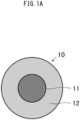
- FIG. 1A illustrates an example of a capsule 10.
- the capsule 10 has a structure in which an inclusion substance 11 is covered by a wall material 12.
- the inclusion substance 11 is present as a single, unitary and continuous region in the capsule 10. In the following description, such a form is referred to as "mononuclear".
- the inclusion substance 11 is, for example, a desired material such as agricultural chemical, ink, pharmaceutical product, or the like.
- the wall material 12 functions in enhancing handleability of the inclusion substance 11, protecting the inclusion substance 11 from the external environment, and controlling the release rate of the inclusion substance 11.
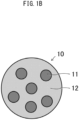
- FIG. 1B illustrates another example of a capsule 10.
- the inclusion substances 11 are discretely distributed in multiple regions in the capsule 10.
- such a form is referred to as "multinuclear”.
- FIG. 1C illustrates still another example of a capsule 10.
- the interior of the capsule 10 is fully filled with a single kind of composite matrix 13 having a sequential composition.
- the composite matrix 13 includes the above-described inclusion substance 11 and wall material 12 mixed in a molecular level. Even if the capsule 10 according to this example is observed using an electron microscope, it is difficult to confirm a boundary between the wall material 12 and the inclusion substance 11.
- FIG. 1C is also referred to as "bead". In the present specification, however, the concept of a "capsule” also includes “bead”. Moreover, a structure in which the mononuclear inclusion substance 11 illustrated in FIG. 1A or the multinuclear inclusion substance 11 illustrated in FIG. 1B is covered by the composite matrix 13 illustrated in FIG. 1C is also included in the concept of a "capsule”. Furthermore, a structure in which the wall material 12 illustrated in FIG. 1A or FIG. 1B and the composite matrix 13 illustrated in FIG. 1C are co-existed is also included in the concept of a "capsule".
- the typical diameter of the above-described capsule 10 is equal to or greater than 10 ⁇ m and is equal to or less than 1 cm, and more specifically, is equal to or greater than 100 ⁇ m and is equal to or less than 5 mm.
- the diameter of the capsule 10 can be measured by observation with a stereoscopic microscope or using a laser diffraction scattering method.
- a capsule production device that produces the capsule 10 is described below.
- a capsule production device 100 includes a rotating tube 110, a rotation device 120 that rotates the rotating tube 110, and a dropping device 130 that decreases, to the rotating tube 110 that has been rotated by the rotation device 120, a raw material liquid 20 that is a precursor of the capsule 10.
- the rotating tube 110 includes a cylindrical body 111 having a shape of cylinder surrounding a virtual center line VL, and a rotation shaft 113 fastened to the cylindrical body 111.
- the rotation shaft 113 is fastened to one end portion, of the cylindrical body 111, in the lengthwise direction parallel to the virtual center line VL.
- the rotation shaft 113 extends and is present on the virtual center line VL.
- a guide groove 112 that helically extends around the virtual center line VL is provided in the inner surface of the cylindrical body 111.
- the guide groove 112 extends from the one end portion, of the cylindrical body 111, in the lengthwise direction to the other end portion thereof.
- the rotating tube 110 is placed in an attitude falling sideways with the rotation shaft 113 being fallen down sideways. More specifically, in the present embodiment, the rotating tube 110 is fallen down horizontally, and the lengthwise direction of the cylindrical body 111 is consistent with the horizontal direction.
- the rotation device 120 rotates the cylindrical body 111 around the virtual center line VL through the rotation shaft 113.
- the dropping device 130 is placed to the end portion of the cylindrical body 111 at, with respect to the lengthwise direction thereof, the opposite side to the end portion where the rotation shaft 113 is fastened.
- the dropping device 130 includes an inner pipe 131, and an outer pipe 132 surrounding the outer side of the inner pipe 131 in a manner concentric with the inner pipe 131.
- a dual pipe includes the inner pipe 131 and the outer pipe 132.
- the inner pipe 131 discharges the inclusion substance 11 in liquid form.
- the outer pipe 132 discharges a wall material precursor liquid 21 that is a precursor of the wall material 12 illustrated in FIG. 1A .
- the discharging of the inclusion substance 11 from the inner pipe 131 and the discharging of the wall material precursor liquid 21 from the outer pipe 132 are performed simultaneously.
- the liquid droplet of the raw material liquid 20 in a form in which the liquid inclusion substance 11 is covered by the wall material precursor liquid 21 is repeatedly dropped from the dropping device 130.
- the diameter of the single droplet of the raw material liquid 20 is, for example, equal to or greater than 0.1 mm and is equal to or less than 5 mm.
- the dropped liquid droplet of the raw material liquid 20 lands at the inner surface of the cylindrical body 111 illustrated in FIG. 2 . It is preferable that the distance between the tip of the inner pipe 131 of the dropping device 130 and the tip of the outer pipe 132 thereof, and the inner surface of the cylindrical body 111 is preferably be equal to or less than 5 cm, more preferably be equal to or less than 2.5 cm, further preferably be equal to or less than 1.5 cm.
- the solidified liquid droplet of the raw material liquid 20 becomes the capsule 10 illustrated in FIG. 1A .
- powders of the solid particulates 30 are placed on the inner surface of the cylindrical body 111 (a powder placing step S1).
- the powers of the solid particulates 30 in powder form are also placed in the guide groove 112.
- the liquid droplets of the raw material liquid 20 are dropped one after another by the dropping device 130 on the inner surface of the cylindrical body 111 while the cylindrical body 111 is being rotated by the rotation device 120 (a dropping step S2).
- the amount of the liquid droplet to be dropped at a time by the dropping device 130 is, for example, equal to or less than 15 ⁇ L.
- each of the liquid droplets of the raw material liquid 20 rolls in the guide groove 112 in the inner surface of the rotating cylindrical body 111 together with the solid particulates 30. This forms a liquid marble 40 in which the surface of the liquid droplet of the raw material liquid 20 is dusted with the solid particulates 30.
- the solid particulates 30 in the liquid marble 40 function as stabilizing the shape of the liquid droplet of the raw material liquid 20 into a spherical shape, and suppressing a unification of the multiple liquid droplets of the raw material liquid 20 into a singular droplet.
- each rolling liquid marble 40 slides in the circumferential direction of the cylindrical body 111, and moves in a direction parallel to the virtual center line VL illustrated in FIG. 2 , more specifically, in a direction from the dropping device 130 toward the rotation shaft 113. Moreover, during such a movement, encapsulation progresses (an encapsulating step S3).
- the term "encapsulation” means that the form of the inclusion substance 11 and that of the wall material precursor liquid 21 become approximate to the form of the capsule 10. More specifically, in the present embodiment, the concept of "encapsulation” includes the solidification of the wall material precursor liquid 21 in the liquid marble 40.
- the liquid droplet of the raw material liquid 20 becomes the capsule 10, and such a capsule 10 is ejected in sequence from the cylindrical body 111 (a capsule ejecting step S4).
- the capsule 10 with a diameter that is substantially equal to or greater than 1.0 mm and equal to or less than 3 mm is obtained.
- the solid particulates 30 are adhered to the capsule 10 ejected from the cylindrical body 111. Hence, the solid particulates 30 adhered to the capsule 10 may be eliminated as needed (a solid particulate eliminating step S5) after the capsule ejecting step S4.
- each of the liquid droplets of the raw material liquid 20 moves within the cylindrical body 111 in one direction while rolling in the guide groove 112 in the form of the liquid marble 40. This suppresses the unification of the multiple liquid droplets of the raw material liquid 20 into a singular droplet, and enables an efficient production of the large number of the capsules 10.
- dusting of the liquid droplet of the raw material liquid 20 with the solid particulates 30 and the solidification of the wall material precursor liquid 21 can be performed successively. This also contributes to the efficient production of the large number of the capsules 10.
- the capsule 10 with a high sphericity can be obtained.
- the term sphericity is an evaluation index that represents the approximation of the shape of the capsule 10 to the shape of a true sphere.
- the capsule 10 in which the wall material 12 has a unified thickness can be obtained. This also contributes to the improvement in the yield of the capsule 10.
- the solid particulate 30 has the diameter that is smaller than that of the liquid droplet of the raw material liquid 20 dropped from the dropping device 130. More specifically, the diameter of the solid particulate 30 is small to an extent that the coating of the liquid droplet of the raw material liquid 20 is possible. More specifically, the diameter of the solid particulate 30 is, for example, equal to or greater than 0.01 ⁇ m and equal to or less than 500 ⁇ m, preferably equal to or greater than 1 ⁇ m and equal to or less than 300 ⁇ m. Note that, in the present specification, the diameter of the solid particulate 30 refers to the average particle diameter with reference to the number of diameters measured by observation with a stereoscopic microscope or a laser diffraction scattering method.
- the solid particulate 30 preferably has appropriate liquid-repellent characteristics against the wall material precursor liquid 21 in order to stably coat the liquid droplet of the raw material liquid 20. More specifically, it is preferable that the solid particulate 30 indicates, a contact angle, to the wall material precursor liquid 21, that is equal to or greater than 70 degrees, preferably equal to or greater than 100 degrees.
- Example water-repellent solid particulate 30 that indicates a contact angle, to water, that is equal to or greater than 70 degrees, preferably equal to or greater than 100 degrees is applicable.
- Example water-repellent solid particulate 30 is, for example, fluorine resin such as polytetrafluoroethylene, or minute particles such as alkylated silica particles, carbon black, polyvinylidene fluoride, and poly[2-(perfluorooctyl)ethyl acrylate].
- a silicone monolith substance of aerogel or xerogel with polysiloxane structure is applicable as the water-repellent solid particulate 30, for example.
- the silicone monolith substance can be obtained by, for example, adopting both bifunctional alkoxysilane and trifunctional alkoxysilane or tetrafunctional alkoxysilanes as starting materials, and copolymerization of such silanes by a sol-gel reaction.
- An example of such a silicone monolith substance is a silicone monolith substance of aerogel or xerogel obtained from vinyltrimethoxysilane and methylvinyldimethoxysilane.
- Such materials are described in the report by HAYASE, et al. (Angew. Chem. Int. Ed. Engl. 2013, 52 (41), pp. 10788-10791 ).
- a water-repellent and oleophobic solid particulate 30 is also applicable.
- the term water-repellent and oleophobic means having water-repellent characteristics and oil-repellent characteristics.
- the solid particulate 30 that indicates a contact angle to water that is equal to or greater than 70 degrees, preferably equal to or greater than 100 degrees, and indicates a contact angle to n- hexadecane that is equal to or greater than 70 degrees, preferably equal to or greater than 100 degrees can be considered as being water-repellent and oleophobic.
- An example water-repellent and oleophobic solid particulate 30 is a silicone monolith substance of a material having a polysiloxane structure and a perfluoroalkyl structure, preferably, aerogel or xerogel having a polysiloxane structure and a perfluoroalkyl structure.
- a material having a polysiloxane structure and a perfluoroalkyl structure preferably, aerogel or xerogel having a polysiloxane structure and a perfluoroalkyl structure.
- marshmallow gel that is a flex porous material indicating water-repellent characteristics and oleophobic characteristics and described in the report by HAYASE, et al. (Angew. Chem. Int. Ed. Engl. 2013, 52(41), pp. 10788-10791 ) is applicable.
- the water-repellent and oleophobic solid particulate 30 for example, particulates of carbon, polyvin
- the wall material precursor liquid 21 is preferably hydrophobic and the solid particulate 30 is preferably water-repellent and oleophobic, or the wall material precursor liquid 21 is preferably hydrophilic and the solid particulate 30 is preferably water-repellent or water-repellent and oleophobic.
- the solidification of the wall material precursor liquid 21 can be accomplished by, for example, (a) gelation of the wall material precursor liquid 21, (b) polymerization of the wall material precursor liquid 21, (c) elimination of the solvent contained in the wall material precursor liquid 21, or a combination of two or more of (a) to (c) selected as appropriate.
- the capsule production device 100 may include a solidification facilitating device 140 that accomplishes the facilitation of the solidification.
- the solidification facilitating device 140 facilitates the solidification of the wall material precursor liquid 21 in the liquid marble 40 moving in the cylindrical body 111 in one direction in the above-described encapsulating step S3. A more specific description is given below.
- the solidification facilitating device 140 cools or heats the liquid marble 40.
- the cooling can be accomplished by, for example, Peltier element, refrigeration cycle, and the like.
- the heating can be accomplished by, for example, Peltier element, infrared lamp, and the like.
- the capsule production device 100 When, however, the capsule production device 100 is placed under a temperature environment at a room temperature that is, for example, equal to or higher than 15°C and equal to or lower than 25°C, and the gelation of the wall material precursor liquid 21 occurs voluntary due to asymptotic action, to the room temperature, of the wall material precursor liquid 21 heated to a temperature higher than the room temperature in advance or of the wall material precursor liquid 21 cooled to a temperature lower than the room temperature in advance, the solidification facilitating device 140 is unnecessary.
- the solidification facilitating device 140 executes a process of facilitating the polymerization of the wall material precursor liquid 21 to the liquid marble 40 that is moving in the cylindrical body 111 in one direction.
- the solidification facilitating device 140 emits such light to the liquid marble 40.
- a structure that causes light emitted from the exterior of the cylindrical body 111 to pass through the cylindrical body 111, and to be incident upon the liquid marble 40 may be employed.
- the wavelength of light is, for example, 380 nm to 780 nm.
- the solidification facilitating device 140 heats the liquid marble 40.
- a heating temperature is, for example, 30°C to 80°C.
- the solidification facilitating device 140 is unnecessary.
- the hydrophobic monomer refers to a monomer having solubility less than 2 mass% relative to water of 25°C
- the hydrophilic monomer refers to a monomer having solubility equal to or higher than 2 mass% relative to water of 25°C.
- Example hydrophobic monomers are: monofunctional acrylate, such as isopropyl acrylate, n-butyl acrylate, isobutyl acrylate, n-amyl acrylate, isoamyl acrylate, n-hexyl acrylate, 2-ethylhexyl acrylate, n-octyl acrylate, decyl acrylate, or dodecyl acrylate; multifunctional acrylate, such as ethylene glycol diacrylate, polyethylene glycol diacrylate, trimethylol propane triacrylate, or pentaerythritol tetraacrylate; monofunctional methacrylate, such as ethyl methacrylate, propyl methacrylate, n-butyl methacrylate, isobutyl methacrylate, n-amyl methacrylate, n-hexyl methacrylate, 2-ethyl hexyl methacrylate,
- the hydrophobic monomer may be applied alone, or two or more kinds thereof may be applied together.
- (meta) acrylate, styrene and divinylbenzene are preferable from the standpoint of the mechanical strength of the wall material 12 of the capsule 10.
- (meta) acrylate refers to monofunctional or multifunctional acrylate and/or methacrylate.
- Example hydrophilic monomers are acrylic acid, methacrylic acid, maleic acid, fumaric acid, vinyl sulfonic acid, styrene sulfonic acid, vinyl alcohol, acrylic amide, and methacryloroxyethylphosphate.
- the hydrophilic monomer may be applied alone, or two or more kinds thereof may be applied together.
- the wall material precursor liquid 21 may also contain constituents, other than a monomer, a polymerization initiator, such as a thermal polymerization initiator or a photopolymerization initiator, a solvent to dissolve or disperse monomers, a surfactant, an UV absorber, a light stabilizer, an oxidation inhibitor, a fire retarder, a plasticizer, wax, and the like.
- a polymerization initiator such as a thermal polymerization initiator or a photopolymerization initiator
- a solvent to dissolve or disperse monomers a surfactant, an UV absorber, a light stabilizer, an oxidation inhibitor, a fire retarder, a plasticizer, wax, and the like.
- Example thermal polymerization initiators are: azo compound, such as 2,2'-azobis(4-methoxy-2,4-dimethylvaleronitrile), 2,2'-azobis(2,4-dimethylvaleronitrile), dimethyl-2,2'-azobis(2-methyl propionate), 2,2'-azobis(2-methylbutyronitrile), 1,1'-azobis(cyclohexane-1 -carbonitrile), 2,2'-azobis[N-(2-propenyl)2-methypropioneamide], 1-[(1-cyano-1-methylethyl)azo]formamide, 2,2'-azobis (N-butyl-2-methypropioneamide), or 2,2'-azobis (N-cyclohexyl-2- methypropioneamide); and peroxide, such as t-butyl peroxybenzoate, or 2,5-dimethyl-2,5-di(t-butylperoxy) hexane.
- peroxide such as
- azo compound is preferable, and 2,2'-azobis(4-methoxy-2,4-dimethylvaleronitrile) is more preferable.
- the blending amount of the thermal polymerization initiator is preferably equal to or greater than 0.01 mol% and equal to or less than 5 mol% relative to a monomer.
- Example photopolymerization initiators are: acetophenone-based compound like diethoxy acetophenone; benzoin-based compound, such as benzoin, benzoin methyl ether, or benzoin isopropyl ether; acyl-phosphine-oxide-based compound like 2,4,6-trimethyl benzoin diphenyl phosphine oxide; benzophenone-based compound, such as benzophenone, or hydroxy benzophenone; thioxanthone-based compound, such as 2-isopropyl thioxanthone, or 2,4-dimethyl thioxanthone; amino-benzophenone-based compound like 4,4'-diethylamino benzophenone; 10-butyl-2-chloroacridone; 2-ethyl anthraquinone; 9,10-phenanthrenequinone; and camphorquinone.
- the blending amount of photopolymerization initiator is preferably equal to or greater than 0.
- the photopolymerization initiator can be applied for a monomer in combination with a photopolymerization promoter as needed in order to make the solidification of the monomer further efficient.
- Example photopolymerization promoters are: benzoic-acid-based compound, such as 4-dimethylamino benzoic acid, 4-dimethyl ethyl aminobenzoic acid, 4-dimethylamino benzoic acid n- butoxyethyl, 4-dimethylamino benzoic acid isoamyl, 4-dimethylamino benzoic acid 2-ethylhexyl; and tertiary amine compound, such as triethanolamine, methyl diethanolamine, triisopropanol amine, 4,4'-dimethylamino benzophenone, or 4,4'-diethylamino benzophenone.
- the blending amount of the photopolymerization promoter is preferably equal to or greater than 0.01 mol% and equal to or less than 5 mol% relative to a monomer.
- the solidification facilitating device 140 heats the liquid marble 40 that is moving the cylindrical body 111 in one direction in order to facilitate the elimination of the solvent contained in the wall material precursor liquid 21.
- the solidification facilitating device 140 is unnecessary.
- an example wall material precursor liquid 21 that contains a solvent is a polymer solution in which a polymer is dissolved in an organic solvent.
- Example polymers applicable include a polymer derived from the above-described hydrophobic monomer or hydrophilic monomer, preferably poly(meta)acrylate, polystyrene and poly-divinylbenzene. Moreover, polylactic acid, polyglycolic acid, a copolymer of lactic acid and glycolate, polycaprolactone, and the like are also applicable.
- Example organic solvents applicable are acetone, methanol, ethanol, dimethyl sulfoxide, dichloroethane, dichloromethane, hexane, toluene, xylene, ethyl acetate, chloroform, diethyl ether, and the like.
- the polymer solution may contain constituents, other than a polymer and a solvent, a surfactant, an UV absorber, a light stabilizer, an oxidation inhibitor, a fire retarder, a plasticizer, wax, and the like.
- the inclusion substance 11 is Medium Chain Triglyceride (MCT) that is middle chain fatty acid.
- the wall material 12 is agarose gel.
- MCT Medium Chain Triglyceride
- the wall material precursor liquid 21 an agarose aqueous solution with a concentration that is 3 mass% and is heated to a higher temperature than the room temperature in advance was applied. The density of the agarose aqueous solution is greater than the density of MCT.
- the amount of the raw material liquid 20 dropped by the dropping device 130 at a time was adjusted so as to be equal to or greater than 8 ⁇ L and equal to or less than 10 ⁇ L.
- the dropping device 130 dropped the amount of 0.5 mL of droplets per a minute.
- the wall material precursor liquid 21 occupied the liquid droplet of the raw material liquid 20 by equal to or greater than 85 volume % and equal to or less than 95 volume %, and the inclusion substance 11 occupied the remaining.
- the solid particulate 30 a fluorine-resin-made substance with a diameter that was substantially 6 ⁇ 2 ⁇ m was applied.
- the liquid droplets of the raw material liquid 20 rolled in the guide groove 112 together with the fluorine-resin-made solid particulates 30 the liquid droplets of the raw material liquid 20 were dusted with the fluorine-resin-made solid particulates 30, and thus the liquid marbles 40 were formed.
- the agarose aqueous solution that is the wall material precursor liquid 21 was cooled.
- the agarose aqueous solution turned into a gel. Consequently, the mononuclear capsule 10 that has the wall material 12 formed of the agarose gel was obtained.
- the capsule 10 were ejected from an end portion of the cylindrical body 111 in sequence.
- the circumferential velocity of the inner surface of the cylindrical body 111 was changed variously.
- the circumferential velocity of the inner surface of the cylindrical body 111 being 0.08 m/s is defined as Example A1
- the circumferential velocity of the inner surface of the cylindrical body 111 being 0.13 m/s is defined as Example A2
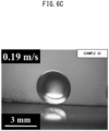
- the circumferential velocity of the inner surface of the cylindrical body 111 being 0.19 m/s is defined as Example A3
- the circumferential velocity of the inner surface of the cylindrical body 111 being 0.24 m/s is defined as Example A4
- the circumferential velocity of the inner surface of the cylindrical body 111 being 0.32 m/s is defined as Example A5
- the circumferential velocity of the inner surface of the cylindrical body 111 being 0.42 m/s is defined as Example A6.
- the sphericity that represents the approximation to the true sphere in shape, the wall-thickness uniformity that represents the uniformity of the thickness of the wall material 12, the success rate of the production of the capsule 10, and the inclusion-substance content percentage that is the content percentage of the inclusion substance 11 were measured.
- the definitions of those evaluation indices are specifically described below.
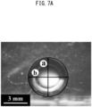
- the definition of the sphericity is described.
- a longest diameter a of the capsule 10 in a spherical shape, and a shortest diameter b are measured.
- the sphericity [%] is defined as b/a ⁇ 100.
- the definition of the wall-thickness uniformity is described.
- a thickness d of the wall materials 12 at the part where the wall material 12 is thickest a radius c of the position including a line that represents the thickness d
- a thickness f of the wall material 12 at a part where the wall material 12 is thinnest a radius e of the position including the line that represents the thickness f are measured.
- the wall-thickness uniformity [%] is defined as (f/e)/(d/c) ⁇ 100.
- the success rate [%] is defined as (the total number of the products recognizable as the capsules 10)/(the total number of the liquid droplets of the raw material liquid 20 dropped by the dropping device 130) ⁇ 100. Note that the success rate was obtained at a stage prior to the drying process and at a stage after the drying process. This is because that there is a possibility such that the wall material 12 is damaged by the above-described drying process, and when the damage of the wall materials 12 is confirmed, the leakage of the inclusion substance 11 may occur, and such a case cannot be recognized as the successful production of the capsule 10.
- FIG. 8 illustrates the dependence properties of the above-described sphericity, wall-thickness uniformity, and success rate to the circumferential velocity of the inner surface of the cylindrical body 111.
- the vertical axis in FIG. 8 represents the sphericity [%], the wall-thickness uniformity [%], and the success rate [%], and the horizontal axis represents the circumferential velocity [m/s] of the inner surface of the cylindrical body 111.
- the circumferential velocity of the inner surface of the cylindrical body 111 is equal to or faster than 0.08 m/s and equal to or slower than 0.24 m/s, the sphericity [%], the wall-thickness uniformity [%], and the success rate [%] relatively become high.
- the circumferential velocity of the inner surface of the cylindrical body 111 is preferably equal to or faster than 0.08 m/s and equal to or slower than 0.24 m/s.
- the circumferential velocity of the inner surface of the cylindrical body 111 is more preferably equal to or faster than 0.08 m/s and equal to or slower than 0.19 m/s, most preferably 0.13 m/s.
- the sphericity was 98 ⁇ 2 [%]
- the wall-thickness uniformity was 88 ⁇ 11 [%]
- the success rate before the drying process and the success rate after the drying process were 100 [%] and 100 [%].
- the inclusion-substance content percentage [%] defined by (the mass [g] of the inclusion substance 1 1)/(the mass [g] of the capsule 10 before the drying process) ⁇ 100 was 77 [%].
- the capsule 10 was produced under the same conditions as those of Example A except that, as the solid particulates 30, edible material, more specifically, soybean wax powders that contain linoleic acid as primary constituent was applied.
- the diameter of the soybean wax powder applied as the solid particulate 30 was 64 ⁇ 30 ⁇ m. Since the solid particulates 30 were edible, even when the capsule 10 were to be adopted as edible, the solid particulate eliminating step S5 illustrated in FIG. 4 can be omitted. Note that the circumferential velocity of the inner surface of the cylindrical body 111 was set to be 0.13 m/s like the case of Example A2.
- FIG. 9 illustrates a micrograph of the capsule 10 according to Example B.
- the sphericity was 98 ⁇ 2 [%]
- the wall-thickness uniformity was 91 ⁇ 16 [%]
- the success rate before the drying process was 100 [%]
- the success rate after the drying process was 100 [%]
- the inclusion-substance content percentage [%] was 71 [%].
- the mononuclear capsule 10 illustrated in FIG. 1A was produced by utilizing the capsule production device 100 illustrated in FIG. 2 .
- the inclusion substance 11 according to the present example was tetradecane that is a heat storage material.
- the heat storage material is a substance that stores thermal energy, and can release the stored energy when necessary.
- the wall material 12 according to the present example was gelatin. A gelatin aqueous solution with a concentration that was 20 mass% was applied as the wall material precursor liquid 21.
- the mononuclear capsule 10 was produced under the conditions such that both the discharge rate of tetradecane as the inclusion substance 11 from the dropping device 130 illustrated in FIG. 3 , and the discharge rate of the gelatin aqueous solution as the wall material precursor liquid 21 were set to be 0.25 mL/min and the circumferential velocity of the inner surface of the cylindrical body 111 was 0.19 m/s. Other production conditions were the same as those of Example A. Consequently, the mononuclear capsule 10 that contained therein tetradecane as the heat storage material was obtained.
- the content percentage of tetradecane in the obtained capsule 10 was 91 [%] with reference to a volume after the drying process. Moreover, according to the capsule 10 of the present example, the sphericity was 98 ⁇ 1 [%], the wall-thickness uniformity was 61 ⁇ 8 [%], and both the success rate before the drying process and the success rate after the drying process were 100 [%].
- the capsule 10 of the present example can contribute to energy saving.
- the capsule 10 that contains therein the heat storage material can be efficiently obtained in sequence.
- the content percentage of tetradecane in the capsule 10 can be increased to 91 [%].
- the solid particulates 30 are placed on the inner surface of the cylindrical body 111, but the placement of the solid particulate 30 may be omitted. The details thereof are described below.
- the liquid droplets of the raw material liquid 20 directly contact the inner surface of the guide groove 112 in the interior of the cylindrical body 111. That is, according to the present embodiment, the powder placing step S1 illustrated in FIG. 4 is omitted.
- the pitch P of the guide groove 112 is preferably 1.2 times or more as much as the average diameter of the liquid droplets, more preferably 1.5 times or more, further preferably 2 times or more.
- the average diameter of the liquid droplets thereof is substantially 3.8 mm.
- the pitch P of the guide groove 112 is preferably equal to or larger than 4.5 mm, more preferably equal to or larger than 5.7 mm, further preferably equal to or larger than 7.6 mm.
- the liquid droplet of the raw material liquid 20 preferably maintains a substantially spherical shape on the inner surface of the guide groove 112 by own surface tension.
- the inner surface of the cylindrical body 111 including the inner surface of the guide groove 112 is preferably liquid-repellent to the raw material liquid 20.
- the inner surface of the cylindrical body 111 including the inner surface of the guide groove 112 indicates, to the raw material liquid 20, a contact angle that is equal to or larger than 100 degrees, preferably equal to or larger than 150 degrees, it can be considered that the inner surface of the cylindrical body 111 including the inner surface of the guide groove 112 is liquid-repellent to the raw material liquid 20.
- the cylindrical body 111 itself, or the surface layer portion of the inner surface of the cylindrical body 111 including the surface layer portion of the inner surface of the guide groove 112 may be formed of a material exemplified as the already-described material of the solid particulate 30. This gives the liquid-repellent characteristics to the cylindrical body 111.
- FIG. 2 illustrates the cylindrical body 111 as an example tubular body that surrounds the virtual center line VL.
- the cylindrical body 111 has a straight shape such that the distance between the inner surface and the virtual center line VL is constant in the lengthwise direction of the virtual center line VL, that is, the generatrix is in parallel with the virtual center line VL.
- the straight shape is not always requisite for the tubular body.
- a concept "tubular body" that surrounds the virtual center line VL also includes a shape that has a portion where the distance between the inner surface and the virtual center line VL changes in the lengthwise direction of the virtual center line VL, for example, a tapered shape having the generatrix inclined relative to the virtual center line VL.
- FIG. 2 illustrates the helical guide groove 112 as an example, but the guide groove where the liquid droplets rolls may circle.
- an Embodiment that utilizes a tapered cylindrical body having a circling guide groove in the inner surface is described as another example tubular body.
- a cylindrical body 114 of the present embodiment has a spreading shape of which an inner diameter gradually increases from an end portion at a side where the dropping device 130 is placed toward an end portion at a side where the capsule 10 is ejected relative to the parallel direction to the virtual center line VL.
- a guide groove 115 according to the present embodiment includes a plurality of circling grooves 115a arranged side by side in the lengthwise direction parallel to the virtual center line VL.
- each of the liquid droplets of the raw material liquid 20 also rolls in the guide groove 115 in the form of the liquid marble 40. Since the generatrix of the cylindrical body 114 is inclined downwardly as becoming apart from the dropping device 130, each rolling liquid marble 40 slides in the circumferential direction of the cylindrical body 115, and moves downwardly along the generatrix by own weight. Moreover, during such a movement, the solidification of the wall material precursor liquid 21 in each liquid marble 40 progresses. Other structures and actions are similar to those of Embodiment 1.
- the inclusion substance 11 can be selected in accordance with the application of the capsule 10. As for the inclusion substance 11, the oil-soluble substance or the water-soluble substance are both applicable. The inclusion substance 11 may be applied alone, or two or more kinds may be applied together.
- Example oil-soluble inclusion substances 11 are oil-soluble agricultural chemical, adhesive, ink, heat storage material, pharmaceutical product, and the like. More specifically, for example, a cold medium like tetradecane, liposoluble vitamin groups like ⁇ -tocopherol, and an anticancer drug like doxorubicin are applicable as the oil-soluble inclusion substance 11.
- Example water-soluble inclusion substances 11 are water-soluble agricultural chemical, adhesive, ink, heat storage material, pharmaceutical product, and the like. More specifically, a solvent like water, and protein substance like bovine serum albumin are applicable as the water-soluble inclusion substance 11.
- the inclusion substance 11 may be volatile or nonvolatile. Moreover, the inclusion substance 11 may be applied in a state dissolved in a solvent.
- the solvent can be selected in accordance with the applied inclusion substance 11.
- organic solvents such as acetone, methanol, ethanol, dimethyl sulfoxide, dichloroethane, dichloromethane, hexane, xylene, ethyl acetate, chloroform, and diethyl ether, are applicable.
- the inclusion substance 11 is water-soluble, for example, a solvent like water is applicable.
Landscapes
- Chemical & Material Sciences (AREA)
- Health & Medical Sciences (AREA)
- Organic Chemistry (AREA)
- Life Sciences & Earth Sciences (AREA)
- General Health & Medical Sciences (AREA)
- Chemical Kinetics & Catalysis (AREA)
- Dispersion Chemistry (AREA)
- Pharmacology & Pharmacy (AREA)
- Veterinary Medicine (AREA)
- Public Health (AREA)
- Animal Behavior & Ethology (AREA)
- Medicinal Chemistry (AREA)
- Epidemiology (AREA)
- Engineering & Computer Science (AREA)
- Bioinformatics & Cheminformatics (AREA)
- Plant Pathology (AREA)
- Wood Science & Technology (AREA)
- Zoology (AREA)
- Environmental Sciences (AREA)
- Dentistry (AREA)
- Toxicology (AREA)
- Pest Control & Pesticides (AREA)
- Agronomy & Crop Science (AREA)
- Food Science & Technology (AREA)
- Polymers & Plastics (AREA)
- Manufacturing Of Micro-Capsules (AREA)
Abstract
Description
- The present disclosure relates to a capsule production method and a capsule production device.
- As disclosed in
Patent Literature 1, a capsule having a structure in which an inclusion substance is covered by a wall material is known. Inclusion substances are, for example, desired materials such as agricultural chemicals, inks, pharmaceutical products, and the like. The wall material functions in enhancing handleability of the inclusion substance, protecting the inclusion substance from the external environment, and controlling a release rate of the inclusion substance. -
Patent Literature 1 proposes a capsule production method as described below. First, a liquid droplet of a raw material liquid containing a monomer liquid or a polymer liquid that is a precursor of the wall material, and the inclusion substance is dropped onto the surface of a flat plate. The dropped liquid droplet maintains the spherical shape by surface tension. Next, the monomer liquid or the polymer liquid is solidified so as to be the wall material. Consequently, a capsule is obtained. - Patent Literature 1: Unexamined
Japanese Patent Application Publication No. 2016-087479 - According to the above-described conventional capsule production method, when a large number of liquid droplets are placed on the flat plate, unification, two liquid droplets or three or more liquid droplets being unified into a singular droplet, is likely to occur. This is one of the factors that make an efficient capsule production difficult.
- An objective of the present disclosure is to provide a capsule production method capable of efficiently producing a capsule, and a capsule production device applicable in the implementation of such a capsule production method.
- A capsule production method according to the present disclosure to be performed by utilizing a tubular body having a shape of tube surrounding a virtual center line, the tubular body including a guide groove that is helical or circles about the virtual center line, the guide groove being provided in an inner surface of the tubular body, includes:
- a dropping step of dropping, on the inner surface of the tubular body, an inclusion substance and a wall material precursor liquid that is a precursor of a wall material covering the inclusion substance;
- an encapsulating step of progressing an encapsulation of the inclusion substance and the wall material precursor liquid by a liquid droplet dropped in the dropping step rolling in the guide groove of the tubular body, the tubular body rotating around the virtual center line; and
- a capsule ejecting step of ejecting, from the tubular body, a capsule obtained by a progress of the encapsulation.
- The above-described method may further include a powder placing step, prior to the dropping step, of placing powders of solid particulates in the guide groove of the tubular body in advance, the solid particulates being each smaller than the liquid droplet, wherein
in the encapsulating step, a liquid marble may be formed by the liquid droplet rolling together with the solid particulates in the guide groove of the tubular body rotating, and the liquid droplet may roll in the guide groove in a form of the liquid marble, the liquid marble being the liquid droplet having a surface that is dusted with the solid particulates. - In the above-described method, a surface of the guide groove of the tubular body may be liquid-repellent to the liquid droplet.
- In the above-described method, an amount of the liquid droplet to be dropped at a time in the dropping step may be equal to or less than 15 µL, and a circumferential velocity of the inner surface of the tubular body in the dropping step and in the encapsulating step may be equal to or faster than 0.08 m/s and equal to or slower than 0.24 m/s.
- In the above-described method, the wall material precursor liquid may have a characteristic of gelation, and the encapsulation may progress by the gelation of the wall material precursor liquid.
- In the above-described method, the wall material precursor liquid may contain a monomer, and the encapsulation may progress by polymerization of the monomer.
- In the above-described method, the wall material precursor liquid may contain a solvent, and the encapsulation may progress by elimination of the solvent.
- A capsule production device according to the present disclosure includes:
- a tubular body having a shape of tube surrounding a virtual center line, the tubular body including a guide groove that is helical or circles about the virtual center line, the guide groove being provided in an inner surface of the tubular body;
- a rotation device to cause the tubular body to rotate around the virtual center line; and
- a dropping device to drop, on the inner surface of the tubular body, an inclusion substance and a wall material precursor liquid that is a precursor of a wall material covering the inclusion substance, wherein
- an encapsulation of the inclusion substance and the wall material precursor liquid progresses by a liquid droplet dropped by the dropping device rolling in the guide groove of the tubular body being rotated by the rotation device.
- In the above-described device, an amount of the liquid droplet to be dropped at a time by the dropping device may be equal to or less than 15 µL.
- The above-described device may further include a solidification facilitating device to facilitate solidification of the wall material precursor liquid in the liquid droplet that is rolling in the guide groove of the tubular body.
- The capsule production method of the present disclosure achieves an efficient production of capsules.
-
-
FIG. 1A is a conceptual diagram illustrating an example capsule; -
FIG. 1B is a conceptual diagram illustrating another example capsule; -
FIG. 1C is a conceptual diagram illustrating still another example capsule; -
FIG. 2 is a conceptual diagram illustrating a structure of a capsule production device according toEmbodiment 1; -
FIG. 3 is a conceptual diagram illustrating a major portion of a dropping device according toEmbodiment 1; -
FIG. 4 is a flowchart of a capsule production according toEmbodiment 1; -
FIG. 5 is a cross-sectional view illustrating a guide groove in a tubular body according toEmbodiment 1 in an enlarged manner; -
FIG. 6A is a micrograph of a capsule according to Example A1; -
FIG. 6B is a micrograph of a capsule according to Example A2; -
FIG. 6C is a micrograph of a capsule according to Example A3; -
FIG. 6D is a micrograph of a capsule according to Example A4; -
FIG. 6E is a micrograph of a capsule according to Example A5; -
FIG. 6F is a micrograph of a capsule according to Example A6; -
FIG. 7A is a micrograph of a capsule to describe a definition of sphericity; -
FIG. 7B is a micrograph of a capsule to describe a definition of wall-thickness uniformity; -
FIG. 8 is a graph showing the relation among, in the capsule production device, the circumferential velocity of the inner surface of a tubular body, the sphericity of an obtained capsule, the wall-thickness uniformity, and a success rate; -
FIG. 9 is a micrograph of a capsule according to Example B; -
FIG. 10 is a cross-sectional view of a guide groove in a tubular body according toEmbodiment 2 in an enlarged manner; -
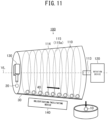
FIG. 11 is a conceptual diagram illustrating a structure of a capsule production device according toEmbodiment 3; and -
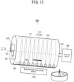
FIG. 12 is a conceptual diagram illustrating a structure of a capsule production device according to Modified Example. - With reference to
FIGS. 1A to 1C , first, example forms of a capsule are described. -
FIG. 1A illustrates an example of acapsule 10. Thecapsule 10 has a structure in which aninclusion substance 11 is covered by awall material 12. In this example, theinclusion substance 11 is present as a single, unitary and continuous region in thecapsule 10. In the following description, such a form is referred to as "mononuclear". - Note that the
inclusion substance 11 is, for example, a desired material such as agricultural chemical, ink, pharmaceutical product, or the like. Thewall material 12 functions in enhancing handleability of theinclusion substance 11, protecting theinclusion substance 11 from the external environment, and controlling the release rate of theinclusion substance 11. -
FIG. 1B illustrates another example of acapsule 10. In this example, theinclusion substances 11 are discretely distributed in multiple regions in thecapsule 10. In the following description, such a form is referred to as "multinuclear". -
FIG. 1C illustrates still another example of acapsule 10. In this example, the interior of thecapsule 10 is fully filled with a single kind ofcomposite matrix 13 having a sequential composition. Thecomposite matrix 13 includes the above-describedinclusion substance 11 andwall material 12 mixed in a molecular level. Even if thecapsule 10 according to this example is observed using an electron microscope, it is difficult to confirm a boundary between thewall material 12 and theinclusion substance 11. - Note that the structure illustrated in
FIG. 1C is also referred to as "bead". In the present specification, however, the concept of a "capsule" also includes "bead". Moreover, a structure in which themononuclear inclusion substance 11 illustrated inFIG. 1A or themultinuclear inclusion substance 11 illustrated inFIG. 1B is covered by thecomposite matrix 13 illustrated inFIG. 1C is also included in the concept of a "capsule". Furthermore, a structure in which thewall material 12 illustrated inFIG. 1A orFIG. 1B and thecomposite matrix 13 illustrated inFIG. 1C are co-existed is also included in the concept of a "capsule". - The typical diameter of the above-described
capsule 10 is equal to or greater than 10 µm and is equal to or less than 1 cm, and more specifically, is equal to or greater than 100 µm and is equal to or less than 5 mm. The diameter of thecapsule 10 can be measured by observation with a stereoscopic microscope or using a laser diffraction scattering method. - A capsule production device that produces the
capsule 10 is described below. - As illustrated in
FIG. 2 , acapsule production device 100 according to the present embodiment includes arotating tube 110, arotation device 120 that rotates therotating tube 110, and adropping device 130 that decreases, to therotating tube 110 that has been rotated by therotation device 120, araw material liquid 20 that is a precursor of thecapsule 10. - The
rotating tube 110 includes acylindrical body 111 having a shape of cylinder surrounding a virtual center line VL, and arotation shaft 113 fastened to thecylindrical body 111. - The
rotation shaft 113 is fastened to one end portion, of thecylindrical body 111, in the lengthwise direction parallel to the virtual center line VL. Therotation shaft 113 extends and is present on the virtual center line VL. Moreover, aguide groove 112 that helically extends around the virtual center line VL is provided in the inner surface of thecylindrical body 111. Theguide groove 112 extends from the one end portion, of thecylindrical body 111, in the lengthwise direction to the other end portion thereof. - The
rotating tube 110 is placed in an attitude falling sideways with therotation shaft 113 being fallen down sideways. More specifically, in the present embodiment, therotating tube 110 is fallen down horizontally, and the lengthwise direction of thecylindrical body 111 is consistent with the horizontal direction. Therotation device 120 rotates thecylindrical body 111 around the virtual center line VL through therotation shaft 113. - The dropping
device 130 is placed to the end portion of thecylindrical body 111 at, with respect to the lengthwise direction thereof, the opposite side to the end portion where therotation shaft 113 is fastened. - As illustrated in
FIG. 3 , the droppingdevice 130 includes aninner pipe 131, and anouter pipe 132 surrounding the outer side of theinner pipe 131 in a manner concentric with theinner pipe 131. A dual pipe includes theinner pipe 131 and theouter pipe 132. Theinner pipe 131 discharges theinclusion substance 11 in liquid form. Theouter pipe 132 discharges a wallmaterial precursor liquid 21 that is a precursor of thewall material 12 illustrated inFIG. 1A . - The discharging of the
inclusion substance 11 from theinner pipe 131 and the discharging of the wall material precursor liquid 21 from theouter pipe 132 are performed simultaneously. Hence, the liquid droplet of theraw material liquid 20 in a form in which theliquid inclusion substance 11 is covered by the wallmaterial precursor liquid 21 is repeatedly dropped from the droppingdevice 130. Note that the diameter of the single droplet of theraw material liquid 20 is, for example, equal to or greater than 0.1 mm and is equal to or less than 5 mm. - The dropped liquid droplet of the
raw material liquid 20 lands at the inner surface of thecylindrical body 111 illustrated inFIG. 2 . It is preferable that the distance between the tip of theinner pipe 131 of the droppingdevice 130 and the tip of theouter pipe 132 thereof, and the inner surface of thecylindrical body 111 is preferably be equal to or less than 5 cm, more preferably be equal to or less than 2.5 cm, further preferably be equal to or less than 1.5 cm. The solidified liquid droplet of theraw material liquid 20 becomes thecapsule 10 illustrated inFIG. 1A . - With reference to a flowchart illustrated in
FIG. 4 , a capsule production method according to the present embodiment is specifically described below. - First, as illustrated in
FIG. 2 , powders of thesolid particulates 30 are placed on the inner surface of the cylindrical body 111 (a powder placing step S1). The powers of thesolid particulates 30 in powder form are also placed in theguide groove 112. - Next, the liquid droplets of the
raw material liquid 20 are dropped one after another by the droppingdevice 130 on the inner surface of thecylindrical body 111 while thecylindrical body 111 is being rotated by the rotation device 120 (a dropping step S2). Note that the amount of the liquid droplet to be dropped at a time by the droppingdevice 130 is, for example, equal to or less than 15 µL. - With reference to
FIG. 5 , the behavior of the liquid droplets dropped in the dropping step S2 is described. Each of the liquid droplets of theraw material liquid 20 rolls in theguide groove 112 in the inner surface of the rotatingcylindrical body 111 together with thesolid particulates 30. This forms aliquid marble 40 in which the surface of the liquid droplet of theraw material liquid 20 is dusted with thesolid particulates 30. - The
solid particulates 30 in theliquid marble 40 function as stabilizing the shape of the liquid droplet of theraw material liquid 20 into a spherical shape, and suppressing a unification of the multiple liquid droplets of theraw material liquid 20 into a singular droplet. - Each of the liquid droplets of the
raw material liquid 20 rolls in theguide groove 112 in the form of theliquid marble 40 as described above. Since theguide groove 112 has a helical shape, each rollingliquid marble 40 slides in the circumferential direction of thecylindrical body 111, and moves in a direction parallel to the virtual center line VL illustrated inFIG. 2 , more specifically, in a direction from the droppingdevice 130 toward therotation shaft 113. Moreover, during such a movement, encapsulation progresses (an encapsulating step S3). - In the present embodiment, the term "encapsulation" means that the form of the
inclusion substance 11 and that of the wallmaterial precursor liquid 21 become approximate to the form of thecapsule 10. More specifically, in the present embodiment, the concept of "encapsulation" includes the solidification of the wallmaterial precursor liquid 21 in theliquid marble 40. - Subsequently, as the encapsulation of each liquid droplet of the raw
material precursor liquid 20, more specifically, the solidification of the wallmaterial precursor liquid 21 in eachliquid marble 40 progresses, the liquid droplet of theraw material liquid 20 becomes thecapsule 10, and such acapsule 10 is ejected in sequence from the cylindrical body 111 (a capsule ejecting step S4). For example, from the liquid droplet of theraw material liquid 20 that is equal to or greater than 1 µL and 10 µL, thecapsule 10 with a diameter that is substantially equal to or greater than 1.0 mm and equal to or less than 3 mm is obtained. - However, the
solid particulates 30 are adhered to thecapsule 10 ejected from thecylindrical body 111. Hence, thesolid particulates 30 adhered to thecapsule 10 may be eliminated as needed (a solid particulate eliminating step S5) after the capsule ejecting step S4. - As discussed above, according to the present embodiment, each of the liquid droplets of the
raw material liquid 20 moves within thecylindrical body 111 in one direction while rolling in theguide groove 112 in the form of theliquid marble 40. This suppresses the unification of the multiple liquid droplets of theraw material liquid 20 into a singular droplet, and enables an efficient production of the large number of thecapsules 10. - Moreover, dusting of the liquid droplet of the
raw material liquid 20 with thesolid particulates 30 and the solidification of the wallmaterial precursor liquid 21 can be performed successively. This also contributes to the efficient production of the large number of thecapsules 10. - Furthermore, since the solidification of the wall
material precursor liquid 21 progresses while theliquid marble 40 is rolling, thecapsule 10 with a high sphericity can be obtained. The term sphericity is an evaluation index that represents the approximation of the shape of thecapsule 10 to the shape of a true sphere. - Still further, since the solidification of the wall
material precursor liquid 21 progresses while theliquid marble 40 is rolling, even when the mass density of the wallmaterial precursor liquid 21 and that of theinclusion substance 11 differ, in particular, even when the mass density of the wallmaterial precursor liquid 21 is greater than the density of theinclusion substance 11, the position of theinclusion substance 11 in the obtainedcapsule 10 is less likely to be displaced. - In particular, when the
mononuclear capsule 10 illustrated inFIG. 1A is produced, thecapsule 10 in which thewall material 12 has a unified thickness can be obtained. This also contributes to the improvement in the yield of thecapsule 10. - The above-described solid particulate 30 is described more specifically in the following.
- The
solid particulate 30 has the diameter that is smaller than that of the liquid droplet of theraw material liquid 20 dropped from the droppingdevice 130. More specifically, the diameter of thesolid particulate 30 is small to an extent that the coating of the liquid droplet of theraw material liquid 20 is possible. More specifically, the diameter of thesolid particulate 30 is, for example, equal to or greater than 0.01 µm and equal to or less than 500 µm, preferably equal to or greater than 1 µm and equal to or less than 300 µm. Note that, in the present specification, the diameter of thesolid particulate 30 refers to the average particle diameter with reference to the number of diameters measured by observation with a stereoscopic microscope or a laser diffraction scattering method. - The solid particulate 30 preferably has appropriate liquid-repellent characteristics against the wall
material precursor liquid 21 in order to stably coat the liquid droplet of theraw material liquid 20. More specifically, it is preferable that thesolid particulate 30 indicates, a contact angle, to the wallmaterial precursor liquid 21, that is equal to or greater than 70 degrees, preferably equal to or greater than 100 degrees. - For example, the water-repellent solid particulate 30 that indicates a contact angle, to water, that is equal to or greater than 70 degrees, preferably equal to or greater than 100 degrees is applicable. Example water-repellent
solid particulate 30 is, for example, fluorine resin such as polytetrafluoroethylene, or minute particles such as alkylated silica particles, carbon black, polyvinylidene fluoride, and poly[2-(perfluorooctyl)ethyl acrylate]. - In addition, as the water-repellent
solid particulate 30, for example, a silicone monolith substance of aerogel or xerogel with polysiloxane structure is applicable. The silicone monolith substance can be obtained by, for example, adopting both bifunctional alkoxysilane and trifunctional alkoxysilane or tetrafunctional alkoxysilanes as starting materials, and copolymerization of such silanes by a sol-gel reaction. An example of such a silicone monolith substance is a silicone monolith substance of aerogel or xerogel obtained from vinyltrimethoxysilane and methylvinyldimethoxysilane. Such materials are described in the report by HAYASE, et al. (Angew. Chem. Int. Ed. Engl. 2013, 52 (41), pp. 10788-10791). - Moreover, a water-repellent and oleophobic
solid particulate 30 is also applicable. In the present specification, the term water-repellent and oleophobic means having water-repellent characteristics and oil-repellent characteristics. For example, the solid particulate 30 that indicates a contact angle to water that is equal to or greater than 70 degrees, preferably equal to or greater than 100 degrees, and indicates a contact angle to n- hexadecane that is equal to or greater than 70 degrees, preferably equal to or greater than 100 degrees can be considered as being water-repellent and oleophobic. - An example water-repellent and oleophobic
solid particulate 30 is a silicone monolith substance of a material having a polysiloxane structure and a perfluoroalkyl structure, preferably, aerogel or xerogel having a polysiloxane structure and a perfluoroalkyl structure. As for such a material, marshmallow gel that is a flex porous material indicating water-repellent characteristics and oleophobic characteristics and described in the report by HAYASE, et al. (Angew. Chem. Int. Ed. Engl. 2013, 52(41), pp. 10788-10791) is applicable. In addition, as the water-repellent and oleophobicsolid particulate 30, for example, particulates of carbon, polyvinylidene fluoride, and the like having a surface modified by perfluoroalkyl group is also applicable. - As for the combination of the wall
material precursor liquid 21 and thesolid particulate 30, the wallmaterial precursor liquid 21 is preferably hydrophobic and thesolid particulate 30 is preferably water-repellent and oleophobic, or the wallmaterial precursor liquid 21 is preferably hydrophilic and thesolid particulate 30 is preferably water-repellent or water-repellent and oleophobic. - Next, the encapsulation in the above-described encapsulating step S3 is described.
- The encapsulation in the present embodiment, more specifically, the solidification of the wall
material precursor liquid 21 can be accomplished by, for example, (a) gelation of the wallmaterial precursor liquid 21, (b) polymerization of the wallmaterial precursor liquid 21, (c) elimination of the solvent contained in the wallmaterial precursor liquid 21, or a combination of two or more of (a) to (c) selected as appropriate. - As illustrated in
FIG. 2 , thecapsule production device 100 may include asolidification facilitating device 140 that accomplishes the facilitation of the solidification. Thesolidification facilitating device 140 facilitates the solidification of the wallmaterial precursor liquid 21 in theliquid marble 40 moving in thecylindrical body 111 in one direction in the above-described encapsulating step S3. A more specific description is given below. - (a) When the wall
material precursor liquid 21 has characteristics to turn in a gel upon being subjected to a temperature change, thesolidification facilitating device 140 applies a temperature change to theliquid marble 40 moving in thecylindrical body 111 in one direction. This facilitates the gelation of the wallmaterial precursor liquid 21. - More specifically, the
solidification facilitating device 140 cools or heats theliquid marble 40. The cooling can be accomplished by, for example, Peltier element, refrigeration cycle, and the like. The heating can be accomplished by, for example, Peltier element, infrared lamp, and the like. - When, however, the
capsule production device 100 is placed under a temperature environment at a room temperature that is, for example, equal to or higher than 15°C and equal to or lower than 25°C, and the gelation of the wallmaterial precursor liquid 21 occurs voluntary due to asymptotic action, to the room temperature, of the wallmaterial precursor liquid 21 heated to a temperature higher than the room temperature in advance or of the wallmaterial precursor liquid 21 cooled to a temperature lower than the room temperature in advance, thesolidification facilitating device 140 is unnecessary. - (b) When the wall
material precursor liquid 21 contains a monomer, thesolidification facilitating device 140 executes a process of facilitating the polymerization of the wallmaterial precursor liquid 21 to theliquid marble 40 that is moving in thecylindrical body 111 in one direction. - More specifically, in the case of photopolymerization that facilitates polymerization by light, the
solidification facilitating device 140 emits such light to theliquid marble 40. A structure that causes light emitted from the exterior of thecylindrical body 111 to pass through thecylindrical body 111, and to be incident upon theliquid marble 40 may be employed. The wavelength of light is, for example, 380 nm to 780 nm. Moreover, in the case of heat polymerization that facilitates polymerization by heating, thesolidification facilitating device 140 heats theliquid marble 40. A heating temperature is, for example, 30°C to 80°C. - When, however, the polymerization of the wall
material precursor liquid 21 that is a monomer occurs voluntary under an environment where thecapsule production device 100 is placed, thesolidification facilitating device 140 is unnecessary. - Note that, as for the monomer, both a hydrophobic monomer and a hydrophilic monomer are applicable. In the present specification, the hydrophobic monomer refers to a monomer having solubility less than 2 mass% relative to water of 25°C, and the hydrophilic monomer refers to a monomer having solubility equal to or higher than 2 mass% relative to water of 25°C.
- Example hydrophobic monomers are: monofunctional acrylate, such as isopropyl acrylate, n-butyl acrylate, isobutyl acrylate, n-amyl acrylate, isoamyl acrylate, n-hexyl acrylate, 2-ethylhexyl acrylate, n-octyl acrylate, decyl acrylate, or dodecyl acrylate; multifunctional acrylate, such as ethylene glycol diacrylate, polyethylene glycol diacrylate, trimethylol propane triacrylate, or pentaerythritol tetraacrylate; monofunctional methacrylate, such as ethyl methacrylate, propyl methacrylate, n-butyl methacrylate, isobutyl methacrylate, n-amyl methacrylate, n-hexyl methacrylate, 2-ethyl hexyl methacrylate, n-octyl methacrylate, or decyl methacrylate; multifunctional methacrylate, such as ethylene glycol dimethacrylate, polyethylene glycol dimethacrylate, trimethylol propane trimethacrylate, or pentaerythritol tetramethacrylate; a styrene-based monomer, such as styrene, α-methyl styrene, vinyl toluene, t-butyl styrene, or chloromethyl styrene; and divinylbenzene. The hydrophobic monomer may be applied alone, or two or more kinds thereof may be applied together. As for the hydrophobic monomer, (meta) acrylate, styrene and divinylbenzene are preferable from the standpoint of the mechanical strength of the
wall material 12 of thecapsule 10. In the present specification, (meta) acrylate refers to monofunctional or multifunctional acrylate and/or methacrylate. - Example hydrophilic monomers are acrylic acid, methacrylic acid, maleic acid, fumaric acid, vinyl sulfonic acid, styrene sulfonic acid, vinyl alcohol, acrylic amide, and methacryloroxyethylphosphate. The hydrophilic monomer may be applied alone, or two or more kinds thereof may be applied together.
- The wall
material precursor liquid 21 may also contain constituents, other than a monomer, a polymerization initiator, such as a thermal polymerization initiator or a photopolymerization initiator, a solvent to dissolve or disperse monomers, a surfactant, an UV absorber, a light stabilizer, an oxidation inhibitor, a fire retarder, a plasticizer, wax, and the like. - Example thermal polymerization initiators are: azo compound, such as 2,2'-azobis(4-methoxy-2,4-dimethylvaleronitrile), 2,2'-azobis(2,4-dimethylvaleronitrile), dimethyl-2,2'-azobis(2-methyl propionate), 2,2'-azobis(2-methylbutyronitrile), 1,1'-azobis(cyclohexane-1 -carbonitrile), 2,2'-azobis[N-(2-propenyl)2-methypropioneamide], 1-[(1-cyano-1-methylethyl)azo]formamide, 2,2'-azobis (N-butyl-2-methypropioneamide), or 2,2'-azobis (N-cyclohexyl-2- methypropioneamide); and peroxide, such as t-butyl peroxybenzoate, or 2,5-dimethyl-2,5-di(t-butylperoxy) hexane. Among these examples, azo compound is preferable, and 2,2'-azobis(4-methoxy-2,4-dimethylvaleronitrile) is more preferable. The blending amount of the thermal polymerization initiator is preferably equal to or greater than 0.01 mol% and equal to or less than 5 mol% relative to a monomer.
- Example photopolymerization initiators are: acetophenone-based compound like diethoxy acetophenone; benzoin-based compound, such as benzoin, benzoin methyl ether, or benzoin isopropyl ether; acyl-phosphine-oxide-based compound like 2,4,6-trimethyl benzoin diphenyl phosphine oxide; benzophenone-based compound, such as benzophenone, or hydroxy benzophenone; thioxanthone-based compound, such as 2-isopropyl thioxanthone, or 2,4-dimethyl thioxanthone; amino-benzophenone-based compound like 4,4'-diethylamino benzophenone; 10-butyl-2-chloroacridone; 2-ethyl anthraquinone; 9,10-phenanthrenequinone; and camphorquinone. The blending amount of photopolymerization initiator is preferably equal to or greater than 0.01 mol% and equal to or less than 5 mol% relative to a monomer.
- The photopolymerization initiator can be applied for a monomer in combination with a photopolymerization promoter as needed in order to make the solidification of the monomer further efficient.
- Example photopolymerization promoters are: benzoic-acid-based compound, such as 4-dimethylamino benzoic acid, 4-dimethyl ethyl aminobenzoic acid, 4-dimethylamino benzoic acid n- butoxyethyl, 4-dimethylamino benzoic acid isoamyl, 4-dimethylamino benzoic acid 2-ethylhexyl; and tertiary amine compound, such as triethanolamine, methyl diethanolamine, triisopropanol amine, 4,4'-dimethylamino benzophenone, or 4,4'-diethylamino benzophenone. The blending amount of the photopolymerization promoter is preferably equal to or greater than 0.01 mol% and equal to or less than 5 mol% relative to a monomer.
- (c) When the wall
material precursor liquid 21 contains a solvent, thesolidification facilitating device 140 heats theliquid marble 40 that is moving thecylindrical body 111 in one direction in order to facilitate the elimination of the solvent contained in the wallmaterial precursor liquid 21. When, however, the vaporization of the solvent progresses voluntary under the environment where thecapsule production device 100 is placed, thesolidification facilitating device 140 is unnecessary. - Note that an example wall
material precursor liquid 21 that contains a solvent is a polymer solution in which a polymer is dissolved in an organic solvent. - Example polymers applicable include a polymer derived from the above-described hydrophobic monomer or hydrophilic monomer, preferably poly(meta)acrylate, polystyrene and poly-divinylbenzene. Moreover, polylactic acid, polyglycolic acid, a copolymer of lactic acid and glycolate, polycaprolactone, and the like are also applicable.
- Example organic solvents applicable are acetone, methanol, ethanol, dimethyl sulfoxide, dichloroethane, dichloromethane, hexane, toluene, xylene, ethyl acetate, chloroform, diethyl ether, and the like.
- The polymer solution may contain constituents, other than a polymer and a solvent, a surfactant, an UV absorber, a light stabilizer, an oxidation inhibitor, a fire retarder, a plasticizer, wax, and the like.
- By utilizing the
capsule production device 100 illustrated inFIG. 2 , themononuclear capsule 10 illustrated inFIG. 1A was produced. Theinclusion substance 11 is Medium Chain Triglyceride (MCT) that is middle chain fatty acid. Thewall material 12 is agarose gel. As for the wallmaterial precursor liquid 21, an agarose aqueous solution with a concentration that is 3 mass% and is heated to a higher temperature than the room temperature in advance was applied. The density of the agarose aqueous solution is greater than the density of MCT. - The amount of the
raw material liquid 20 dropped by the droppingdevice 130 at a time was adjusted so as to be equal to or greater than 8 µL and equal to or less than 10 µL. The droppingdevice 130 dropped the amount of 0.5 mL of droplets per a minute. The wallmaterial precursor liquid 21 occupied the liquid droplet of theraw material liquid 20 by equal to or greater than 85 volume % and equal to or less than 95 volume %, and theinclusion substance 11 occupied the remaining. As for thesolid particulate 30, a fluorine-resin-made substance with a diameter that was substantially 6 ± 2µm was applied. - As the liquid droplets of the
raw material liquid 20 rolled in theguide groove 112 together with the fluorine-resin-madesolid particulates 30, the liquid droplets of theraw material liquid 20 were dusted with the fluorine-resin-madesolid particulates 30, and thus theliquid marbles 40 were formed. - While the
liquid marbles 40 were rolling in theguide groove 112 and were moving in one direction, the agarose aqueous solution that is the wallmaterial precursor liquid 21 was cooled. Hence, the agarose aqueous solution turned into a gel. Consequently, themononuclear capsule 10 that has thewall material 12 formed of the agarose gel was obtained. Thecapsule 10 were ejected from an end portion of thecylindrical body 111 in sequence. - Subsequently, in order to further solidify the
wall material 12, a drying process of repelling moisture in thewall material 12 in a gel shape was executed on each of thecapsule 10 ejected from thecylindrical body 111. - In the above case, in order to find an optimized circumferential velocity of the inner surface of the
cylindrical body 111, the circumferential velocity of the inner surface of thecylindrical body 111 was changed variously. The circumferential velocity of the inner surface of thecylindrical body 111 being 0.08 m/s is defined as Example A1, the circumferential velocity of the inner surface of thecylindrical body 111 being 0.13 m/s is defined as Example A2, the circumferential velocity of the inner surface of thecylindrical body 111 being 0.19 m/s is defined as Example A3, the circumferential velocity of the inner surface of thecylindrical body 111 being 0.24 m/s is defined as Example A4, the circumferential velocity of the inner surface of thecylindrical body 111 being 0.32 m/s is defined as Example A5, and the circumferential velocity of the inner surface of thecylindrical body 111 being 0.42 m/s is defined as Example A6. - In addition, as for the
capsules 10 obtained in Examples A1 to A6, the sphericity that represents the approximation to the true sphere in shape, the wall-thickness uniformity that represents the uniformity of the thickness of thewall material 12, the success rate of the production of thecapsule 10, and the inclusion-substance content percentage that is the content percentage of theinclusion substance 11 were measured. The definitions of those evaluation indices are specifically described below. - With reference to
FIG. 7A , the definition of the sphericity is described. In the micrograph of thecapsule 10 after the above-described drying process, a longest diameter a of thecapsule 10 in a spherical shape, and a shortest diameter b are measured. The sphericity [%] is defined as b/a × 100. - With reference to
FIG. 7B , the definition of the wall-thickness uniformity is described. In the micrograph of thecapsule 10 after the drying process, a thickness d of thewall materials 12 at the part where thewall material 12 is thickest, a radius c of the position including a line that represents the thickness d, a thickness f of thewall material 12 at a part where thewall material 12 is thinnest, and a radius e of the position including the line that represents the thickness f are measured. The wall-thickness uniformity [%] is defined as (f/e)/(d/c) × 100. - The success rate [%] is defined as (the total number of the products recognizable as the capsules 10)/(the total number of the liquid droplets of the
raw material liquid 20 dropped by the dropping device 130) × 100. Note that the success rate was obtained at a stage prior to the drying process and at a stage after the drying process. This is because that there is a possibility such that thewall material 12 is damaged by the above-described drying process, and when the damage of thewall materials 12 is confirmed, the leakage of theinclusion substance 11 may occur, and such a case cannot be recognized as the successful production of thecapsule 10. -
FIG. 8 illustrates the dependence properties of the above-described sphericity, wall-thickness uniformity, and success rate to the circumferential velocity of the inner surface of thecylindrical body 111. The vertical axis inFIG. 8 represents the sphericity [%], the wall-thickness uniformity [%], and the success rate [%], and the horizontal axis represents the circumferential velocity [m/s] of the inner surface of thecylindrical body 111. - As illustrated in
FIG. 8 , when the circumferential velocity of the inner surface of thecylindrical body 111 is equal to or faster than 0.08 m/s and equal to or slower than 0.24 m/s, the sphericity [%], the wall-thickness uniformity [%], and the success rate [%] relatively become high. In view of such results, when the amount of theraw material liquid 20 to be dropped at a time by the droppingdevice 130 is equal to or less than 15 µL, the circumferential velocity of the inner surface of thecylindrical body 111 is preferably equal to or faster than 0.08 m/s and equal to or slower than 0.24 m/s. The circumferential velocity of the inner surface of thecylindrical body 111 is more preferably equal to or faster than 0.08 m/s and equal to or slower than 0.19 m/s, most preferably 0.13 m/s. - Note that according to the
capsule 10 of Example A2, the sphericity was 98 ± 2 [%], the wall-thickness uniformity was 88 ± 11 [%], and the success rate before the drying process and the success rate after the drying process were 100 [%] and 100 [%]. Moreover, the inclusion-substance content percentage [%] defined by (the mass [g] of theinclusion substance 1 1)/(the mass [g] of thecapsule 10 before the drying process) × 100 was 77 [%]. - The
capsule 10 was produced under the same conditions as those of Example A except that, as thesolid particulates 30, edible material, more specifically, soybean wax powders that contain linoleic acid as primary constituent was applied. The diameter of the soybean wax powder applied as thesolid particulate 30 was 64 ± 30 µm. Since thesolid particulates 30 were edible, even when thecapsule 10 were to be adopted as edible, the solid particulate eliminating step S5 illustrated inFIG. 4 can be omitted. Note that the circumferential velocity of the inner surface of thecylindrical body 111 was set to be 0.13 m/s like the case of Example A2. -
FIG. 9 illustrates a micrograph of thecapsule 10 according to Example B. According to thecapsule 10 of Example B, the sphericity was 98 ± 2 [%], the wall-thickness uniformity was 91 ± 16 [%], the success rate before the drying process was 100 [%], the success rate after the drying process was 100 [%], and the inclusion-substance content percentage [%] was 71 [%]. - The
mononuclear capsule 10 illustrated inFIG. 1A was produced by utilizing thecapsule production device 100 illustrated inFIG. 2 . Theinclusion substance 11 according to the present example was tetradecane that is a heat storage material. The heat storage material is a substance that stores thermal energy, and can release the stored energy when necessary. Moreover, thewall material 12 according to the present example was gelatin. A gelatin aqueous solution with a concentration that was 20 mass% was applied as the wallmaterial precursor liquid 21. - More specifically, the
mononuclear capsule 10 was produced under the conditions such that both the discharge rate of tetradecane as theinclusion substance 11 from the droppingdevice 130 illustrated inFIG. 3 , and the discharge rate of the gelatin aqueous solution as the wallmaterial precursor liquid 21 were set to be 0.25 mL/min and the circumferential velocity of the inner surface of thecylindrical body 111 was 0.19 m/s. Other production conditions were the same as those of Example A. Consequently, themononuclear capsule 10 that contained therein tetradecane as the heat storage material was obtained. - The content percentage of tetradecane in the obtained
capsule 10 was 91 [%] with reference to a volume after the drying process. Moreover, according to thecapsule 10 of the present example, the sphericity was 98 ± 1 [%], the wall-thickness uniformity was 61 ± 8 [%], and both the success rate before the drying process and the success rate after the drying process were 100 [%]. - By the encapsulation that utilizes the heat storage material as the
inclusion substance 11 of thecapsule 10, in comparison with a case such that the same heat storage material is utilized as a bulk, the specific surface area can be increased. Hence, heat storage and release can be accelerated. Accordingly, thecapsule 10 of the present example can contribute to energy saving. - According to conventional scheme of producing a capsule in liquid phase, efficient encapsulation of the heat storage material and increase in the content percentage of the heat storage material in the capsule were difficult. In contrast, according to the present example, the
capsule 10 that contains therein the heat storage material can be efficiently obtained in sequence. Moreover, the content percentage of tetradecane in thecapsule 10 can be increased to 91 [%]. - As illustrated in
FIG. 2 , according to above-describedEmbodiment 1, thesolid particulates 30 are placed on the inner surface of thecylindrical body 111, but the placement of thesolid particulate 30 may be omitted. The details thereof are described below. - As illustrated in
FIG. 10 in an enlarged manner, in the present embodiment, the liquid droplets of theraw material liquid 20 directly contact the inner surface of theguide groove 112 in the interior of thecylindrical body 111. That is, according to the present embodiment, the powder placing step S1 illustrated inFIG. 4 is omitted. - Nevertheless, a clearance is secured between the adjacent liquid droplets of the
raw material liquid 20 since a pitch P of thehelical guide groove 112 is larger than the diameter of the liquid droplet of theraw material liquid 20. Hence, the unification such that the adjacent liquid droplets of theraw material liquid 20 are unified into a singular droplet can be prevented. Hence, like a case ofEmbodiment 1, a large number of the capsules can be produced efficiently. - In order to enhance the advantageous effect of suppressing the unification of the liquid droplets of the
raw material liquid 20, the pitch P of theguide groove 112 is preferably 1.2 times or more as much as the average diameter of the liquid droplets, more preferably 1.5 times or more, further preferably 2 times or more. - When, for example, the liquid droplets of the
raw material liquid 20 is 30 µL, the average diameter of the liquid droplets thereof is substantially 3.8 mm. In this case, the pitch P of theguide groove 112 is preferably equal to or larger than 4.5 mm, more preferably equal to or larger than 5.7 mm, further preferably equal to or larger than 7.6 mm. - Moreover, the liquid droplet of the
raw material liquid 20 preferably maintains a substantially spherical shape on the inner surface of theguide groove 112 by own surface tension. In order to do so, the inner surface of thecylindrical body 111 including the inner surface of theguide groove 112 is preferably liquid-repellent to theraw material liquid 20. - When the inner surface of the
cylindrical body 111 including the inner surface of theguide groove 112 indicates, to theraw material liquid 20, a contact angle that is equal to or larger than 100 degrees, preferably equal to or larger than 150 degrees, it can be considered that the inner surface of thecylindrical body 111 including the inner surface of theguide groove 112 is liquid-repellent to theraw material liquid 20. More specifically, thecylindrical body 111 itself, or the surface layer portion of the inner surface of thecylindrical body 111 including the surface layer portion of the inner surface of theguide groove 112 may be formed of a material exemplified as the already-described material of thesolid particulate 30. This gives the liquid-repellent characteristics to thecylindrical body 111. -
FIG. 2 illustrates thecylindrical body 111 as an example tubular body that surrounds the virtual center line VL. Thecylindrical body 111 has a straight shape such that the distance between the inner surface and the virtual center line VL is constant in the lengthwise direction of the virtual center line VL, that is, the generatrix is in parallel with the virtual center line VL. However, the straight shape is not always requisite for the tubular body. In the present specification, a concept "tubular body" that surrounds the virtual center line VL also includes a shape that has a portion where the distance between the inner surface and the virtual center line VL changes in the lengthwise direction of the virtual center line VL, for example, a tapered shape having the generatrix inclined relative to the virtual center line VL. - Moreover,
FIG. 2 illustrates thehelical guide groove 112 as an example, but the guide groove where the liquid droplets rolls may circle. In the following, an Embodiment that utilizes a tapered cylindrical body having a circling guide groove in the inner surface is described as another example tubular body. - As illustrated in
FIG. 11 , acylindrical body 114 of the present embodiment has a spreading shape of which an inner diameter gradually increases from an end portion at a side where the droppingdevice 130 is placed toward an end portion at a side where thecapsule 10 is ejected relative to the parallel direction to the virtual center line VL. Moreover, aguide groove 115 according to the present embodiment includes a plurality of circlinggrooves 115a arranged side by side in the lengthwise direction parallel to the virtual center line VL. - According to the present embodiment, also, each of the liquid droplets of the
raw material liquid 20 also rolls in theguide groove 115 in the form of theliquid marble 40. Since the generatrix of thecylindrical body 114 is inclined downwardly as becoming apart from the droppingdevice 130, each rollingliquid marble 40 slides in the circumferential direction of thecylindrical body 115, and moves downwardly along the generatrix by own weight. Moreover, during such a movement, the solidification of the wallmaterial precursor liquid 21 in eachliquid marble 40 progresses. Other structures and actions are similar to those ofEmbodiment 1. - Embodiments and Examples are described above. Modified Examples (1) to (5) to be described below are also adoptable.
- (1)
FIG. 3 illustrates an example liquid droplet of theraw material liquid 20 that has themononuclear inclusion substance 11 covered by the wallmaterial precursor liquid 21. This liquid droplet is suitable for the production of thecapsule 10 illustrated inFIG. 1A . For example, the dropping nozzle portion that drops theraw material liquid 20 in the droppingdevice 130 may include multiple pipes that are triple pipes or more. This enables a formation of a liquid droplet of theraw material liquid 20 in a form that has themultinuclear inclusion substance 11 covered by the wallmaterial precursor liquid 21. Such a liquid droplet is suitable for the production of thecapsule 10 illustrated inFIG. 1B . Since the encapsulation of theraw material liquid 20 progresses while the liquid droplet of theraw material liquid 20 rolls, when themultinuclear capsule 10 illustrated inFIG. 1B is produced, displacement of theinclusion substance 11 that becomes a nucleus is not likely to occur.
Moreover, by applying theraw material liquid 20 in a form such that theinclusion substance 11 is dispersed in the wallmaterial precursor liquid 21 in a molecular level, or theraw material liquid 20 in a form such that theinclusion substance 11 is dissolved in the wallmaterial precursor liquid 21, thecapsule 10 illustrated inFIG. 1C can be produced. Since the encapsulation of theraw material liquid 20 progresses while the liquid droplets of theraw material liquid 20 roll, when thecapsule 10 illustrated inFIG. 1C is to be produced, the internal composition can be made uniform. - (2) Moreover,
FIG. 3 illustrates an example structure such that theinclusion substance 11 and the wallmaterial precursor liquid 21 are dropped together, but theinclusion substance 11 and the wallmaterial precursor liquid 21 may be dropped separately. Encapsulation may be carried out while theinclusion substance 11 and the wallmaterial precursor liquid 21 that are dropped separately are rolling in theguide groove 112. In this case, the concept of "encapsulation" includes the covering of theinclusion substance 11 by the wallmaterial precursor liquid 21 and the solidification of the wallmaterial precursor liquid 21 that is covering theinclusion substance 11. Note that when theinclusion substance 11 and the wallmaterial precursor liquid 21 are dropped separately, the already-described powder placing step S1 may be omitted. - (3)
FIG. 2 andFIG. 11 illustrate, an examplerotating tube 110 having the virtual center line VL placed horizontally. The virtual center line VL may have a slight inclination angle θ, more specifically, an inclination angle θ that is, for example, equal to or smaller than 60 degrees, preferably equal to or smaller than 30 degrees relative to the horizontal plane. In the present specification, the meaning of the "attitude falling sideways" also includes a case such that the virtual center line VL has such a slight inclination angle θ. For example, in the structure illustrated inFIG. 2 , by causing the virtual center line VL to have an inclination angle θ, thecylindrical body 111 may be inclined downwardly from the end portion at a side where a liquid droplet is dropped toward the end portion at a side where thecapsule 10 is ejected.
FIG. 12 illustrates thecylindrical body 111 having the virtual center line VL with such an inclination angle θ. Eachliquid marble 40 rolling on the inner surface of thecylindrical body 111 slides in the circumferential direction of thecylindrical body 111, and moves downwardly by own weight along the generatrix parallel to the virtual center line VL. According to this structure, like the case ofEmbodiment 3, theguide groove 115 may be configured by the plurality of circlinggrooves 115a arranged side by side along the lengthwise direction parallel to the virtual center line VL. - (4)
FIG. 11 andFIG. 12 illustrate example structures such that the circlingguide groove 115 is provided for thecylindrical bodies helical guide groove 112 may be provided for thecylindrical bodies FIG. 2 illustrates an example structure such that thehelical guide groove 112 is provided for thecylindrical body 111 having the generatrix placed horizontally, but the similar advantageous effects can be accomplished when the circlingguide groove 115 is provided for thecylindrical body 111 having the generatrix placed horizontally. - (5)
FIG. 2 andFIG. 11 illustrate, as an example tubular body that surrounds the virtual center line VL, thecylindrical bodies - Specific examples of the above-described
inclusion substance 11 are described below. - The
inclusion substance 11 can be selected in accordance with the application of thecapsule 10. As for theinclusion substance 11, the oil-soluble substance or the water-soluble substance are both applicable. Theinclusion substance 11 may be applied alone, or two or more kinds may be applied together. - Example oil-
soluble inclusion substances 11 are oil-soluble agricultural chemical, adhesive, ink, heat storage material, pharmaceutical product, and the like. More specifically, for example, a cold medium like tetradecane, liposoluble vitamin groups like α-tocopherol, and an anticancer drug like doxorubicin are applicable as the oil-soluble inclusion substance 11. - Example water-
soluble inclusion substances 11 are water-soluble agricultural chemical, adhesive, ink, heat storage material, pharmaceutical product, and the like. More specifically, a solvent like water, and protein substance like bovine serum albumin are applicable as the water-soluble inclusion substance 11. - The
inclusion substance 11 may be volatile or nonvolatile. Moreover, theinclusion substance 11 may be applied in a state dissolved in a solvent. The solvent can be selected in accordance with the appliedinclusion substance 11. When theinclusion substance 11 is oil-soluble, for example, organic solvents, such as acetone, methanol, ethanol, dimethyl sulfoxide, dichloroethane, dichloromethane, hexane, xylene, ethyl acetate, chloroform, and diethyl ether, are applicable. When theinclusion substance 11 is water-soluble, for example, a solvent like water is applicable. - The foregoing describes some example embodiments for explanatory purposes. Although the foregoing discussion has presented specific embodiments, persons skilled in the art will recognize that changes may be made in form and detail without departing from the broader spirit and scope of the invention. Accordingly, the specification and drawings are to be regarded in an illustrative rather than a restrictive sense. This detailed description, therefore, is not to be taken in a limiting sense, and the scope of the invention is defined only by the included claims, along with the full range of equivalents to which such claims are entitled.
- This application claims the benefit of
Japanese Patent Application No. 2021-98149 filed on June 11, 2021 -
- 10
- Capsule
- 11
- Inclusion substance
- 12
- Wall material
- 13
- Composite matrix
- 20
- Raw material liquid
- 21
- Wall material precursor liquid
- 30
- Solid particulate
- 40
- Liquid marble
- 100
- Capsule production device
- 110
- Rotating tube
- 111
- Cylindrical body (tubular body)
- 112
- Guide groove
- 113
- Rotation shaft
- 114
- Cylindrical body (tubular body)
- 115
- Guide groove
- 115a
- Circling groove
- 120
- Rotation device
- 130
- Dropping device
- 131
- Inner pipe
- 132
- Outer pipe
- 140
- Solidification facilitating device
- VL
- Virtual center line
Claims (10)
- A capsule production method to be performed by utilizing a tubular body having a shape of tube surrounding a virtual center line, the tubular body including a guide groove that is helical or circles about the virtual center line, the guide groove being provided in an inner surface of the tubular body, the method comprising:a dropping step of dropping, on the inner surface of the tubular body, an inclusion substance and a wall material precursor liquid that is a precursor of a wall material covering the inclusion substance;an encapsulating step of progressing an encapsulation of the inclusion substance and the wall material precursor liquid by a liquid droplet dropped in the dropping step rolling in the guide groove of the tubular body, the tubular body rotating around the virtual center line; anda capsule ejecting step of ejecting, from the tubular body, a capsule obtained by a progress of the encapsulation.
- The capsule production method according to claim 1, further comprising:a powder placing step, prior to the dropping step, of placing powders of solid particulates in the guide groove of the tubular body in advance, the solid particulates being each smaller than the liquid droplet, whereinin the encapsulating step, a liquid marble is formed by the liquid droplet rolling together with the solid particulates in the guide groove of the tubular body rotating, and the liquid droplet rolls in the guide groove in a form of the liquid marble, the liquid marble being the liquid droplet having a surface that is dusted with the solid particulates.
- The capsule production method according to claim 1, wherein a surface of the guide groove of the tubular body is liquid-repellent to the liquid droplet.
- The capsule production method according to claim 1 or 2, whereinan amount of the liquid droplet to be dropped at a time in the dropping step is equal to or less than 15 µL, anda circumferential velocity of the inner surface of the tubular body in the dropping step and in the encapsulating step is equal to or faster than 0.08 m/s and equal to or slower than 0.24 m/s.
- The capsule production method according to any one of claims 1 to 4, whereinthe wall material precursor liquid has a characteristic of gelation, andthe encapsulation progresses by the gelation of the wall material precursor liquid.
- The capsule production method according to any one of claims 1 to 4, whereinthe wall material precursor liquid contains a monomer, andthe encapsulation progresses by polymerization of the monomer.
- The capsule production method according to any one of claims 1 to 4, whereinthe wall material precursor liquid contains a solvent, andthe encapsulation progresses by elimination of the solvent.
- A capsule production device comprising:a tubular body having a shape of tube surrounding a virtual center line, the tubular body including a guide groove that is helical or circles about the virtual center line, the guide groove being provided in an inner surface of the tubular body;a rotation device to cause the tubular body to rotate around the virtual center line; anda dropping device to drop, on the inner surface of the tubular body, an inclusion substance and a wall material precursor liquid that is a precursor of a wall material covering the inclusion substance, whereinan encapsulation of the inclusion substance and the wall material precursor liquid progresses by a liquid droplet dropped by the dropping device rolling in the guide groove of the tubular body being rotated by the rotation device.
- The capsule production device according to claim 8, wherein an amount of the liquid droplet to be dropped at a time by the dropping device is equal to or less than 15 IlL.
- The capsule production device according to claim 8 or 9, further comprising:
a solidification facilitating device to facilitate solidification of the wall material precursor liquid in the liquid droplet that is rolling in the guide groove of the tubular body.
Applications Claiming Priority (2)
| Application Number | Priority Date | Filing Date | Title |
|---|---|---|---|
| JP2021098149 | 2021-06-11 | ||
| PCT/JP2022/023403 WO2022260156A1 (en) | 2021-06-11 | 2022-06-10 | Capsule production method and capsule production device |
Publications (2)
| Publication Number | Publication Date |
|---|---|
| EP4353350A1 true EP4353350A1 (en) | 2024-04-17 |
| EP4353350A4 EP4353350A4 (en) | 2024-12-25 |
Family
ID=84424611
Family Applications (1)
| Application Number | Title | Priority Date | Filing Date |
|---|---|---|---|
| EP22820334.5A Pending EP4353350A4 (en) | 2021-06-11 | 2022-06-10 | CAPSULE MANUFACTURING METHOD AND CAPSULE MANUFACTURING APPARATUS |
Country Status (5)
| Country | Link |
|---|---|
| US (1) | US20240359152A1 (en) |
| EP (1) | EP4353350A4 (en) |
| JP (1) | JP7730577B2 (en) |
| CN (1) | CN117460572A (en) |
| WO (1) | WO2022260156A1 (en) |
Family Cites Families (12)
| Publication number | Priority date | Publication date | Assignee | Title |
|---|---|---|---|---|
| US4162282A (en) * | 1976-04-22 | 1979-07-24 | Coulter Electronics, Inc. | Method for producing uniform particles |
| US4379682A (en) * | 1981-04-29 | 1983-04-12 | Ortho Diagnostics, Inc. | Reaction apparatus for the formation of microspheres or microcapsules |
| JP2784872B2 (en) * | 1992-06-12 | 1998-08-06 | 花王株式会社 | Method for producing seamless capsule particles containing surfactant |
| JPH10296069A (en) * | 1997-04-24 | 1998-11-10 | Aramitsuku:Kk | Granulating device |
| WO2006096571A2 (en) * | 2005-03-04 | 2006-09-14 | President And Fellows Of Harvard College | Method and apparatus for forming multiple emulsions |
| GB201113776D0 (en) * | 2011-08-10 | 2011-09-21 | British American Tobacco Co | Capsule formation |
| JP2016087479A (en) | 2014-10-29 | 2016-05-23 | 国立大学法人 鹿児島大学 | Method for producing micro-capsules or beads |
| US11198106B2 (en) * | 2017-08-24 | 2021-12-14 | Kagoshima University | Method for producing microcapsules or beads |
| CN108380148B (en) * | 2018-03-07 | 2019-12-13 | 中国工程物理研究院激光聚变研究中心 | A liquid droplet rotation solidification reaction system simulating microgravity |
| JP7132036B2 (en) | 2018-08-29 | 2022-09-06 | 株式会社コロプラ | GAME PROGRAM, GAME METHOD, AND INFORMATION PROCESSING DEVICE |
| CN109939621B (en) * | 2019-03-08 | 2020-08-11 | 清华大学 | Method for preparing single-particle uniform coating shell layer by liquid phase interface crossing |
| EP3771488B1 (en) * | 2019-07-31 | 2024-09-04 | Ricoh Company, Ltd. | Composite particles, composite particles for forming liquid-encapsulating particles, liquid-encapsulating particles, method for producing liquid-encapsulating particles, biocatalyst-containing material and biocatalyst-containing material producing apparatus, and |
-
2022
- 2022-06-10 WO PCT/JP2022/023403 patent/WO2022260156A1/en not_active Ceased
- 2022-06-10 CN CN202280040943.XA patent/CN117460572A/en active Pending
- 2022-06-10 EP EP22820334.5A patent/EP4353350A4/en active Pending
- 2022-06-10 US US18/569,175 patent/US20240359152A1/en active Pending
- 2022-06-10 JP JP2023527938A patent/JP7730577B2/en active Active
Also Published As
| Publication number | Publication date |
|---|---|
| US20240359152A1 (en) | 2024-10-31 |
| EP4353350A4 (en) | 2024-12-25 |
| JPWO2022260156A1 (en) | 2022-12-15 |
| JP7730577B2 (en) | 2025-08-28 |
| WO2022260156A1 (en) | 2022-12-15 |
| CN117460572A (en) | 2024-01-26 |
Similar Documents
| Publication | Publication Date | Title |
|---|---|---|
| US12343935B2 (en) | Thickness-limited electrospray deposition | |
| Oh et al. | Hydrodynamic micro-encapsulation of aqueous fluids and cells via ‘on the fly’photopolymerization | |
| US11198106B2 (en) | Method for producing microcapsules or beads | |
| WO2015089309A1 (en) | Core-shell multi-layer particles | |
| US20020140118A1 (en) | Focused acoustic energy in the generation of solid particles | |
| Jawahar et al. | Multi unit particulates systems (MUPS): a novel pellets for oral dosage forms | |
| Qiao et al. | A novel electrostatic dry powder coating process for pharmaceutical dosage forms: immediate release coatings for tablets | |
| EP4353350A1 (en) | Capsule production method and capsule production device | |
| CN115532185A (en) | A polyaniline double-layer microcapsule with barrier properties | |
| WO2009111684A1 (en) | Process for making coated, water-swellable hydrogel microspheres | |
| KR20190082197A (en) | Microspheres and manufacturing method thereof | |
| US20180141019A1 (en) | Self-inflating microcapsules | |
| Albanez et al. | Influence of the type of enteric coating suspension, coating layer and process conditions on dissolution profile and stability of coated pellets of diclofenac sodium | |
| TWI376263B (en) | Process for coating powders | |
| Sultan et al. | Rough and Tough: How Particle Surface Roughness Affects Liquid Marble Formation and Stability | |
| JP5830253B2 (en) | Liquid gelling apparatus and liquid gelling method | |
| US20160228332A1 (en) | Multi-layer capsule and manufacture method thereof | |
| JP2001190943A (en) | Method and apparatus for producing multilayer granules | |
| JP2022500282A (en) | Process for the preparation of coated solid pharmaceutical dosage forms | |
| Dhuppe et al. | Recent techniques of pharmaceutical solventless coating: a review | |
| JPH0671159A (en) | Manufacture of filled capsule | |
| Bathool et al. | Pelletization as a key tool for oral drug delivery: A review | |
| Bhattacharjee et al. | Solventless coating for tablet: A technical review | |
| Diwane et al. | REVIEW ON MULTIPARTICULATE SYSTEM A EMERGING TREND IN DRUG DELIVERY SYSTEM | |
| AU2011371241B2 (en) | Multi-layer capsule and manufacture method thereof |
Legal Events
| Date | Code | Title | Description |
|---|---|---|---|
| STAA | Information on the status of an ep patent application or granted ep patent |
Free format text: STATUS: THE INTERNATIONAL PUBLICATION HAS BEEN MADE |
|
| PUAI | Public reference made under article 153(3) epc to a published international application that has entered the european phase |
Free format text: ORIGINAL CODE: 0009012 |
|
| STAA | Information on the status of an ep patent application or granted ep patent |
Free format text: STATUS: REQUEST FOR EXAMINATION WAS MADE |
|
| 17P | Request for examination filed |
Effective date: 20231213 |
|
| AK | Designated contracting states |
Kind code of ref document: A1 Designated state(s): AL AT BE BG CH CY CZ DE DK EE ES FI FR GB GR HR HU IE IS IT LI LT LU LV MC MK MT NL NO PL PT RO RS SE SI SK SM TR |
|
| DAV | Request for validation of the european patent (deleted) | ||
| DAX | Request for extension of the european patent (deleted) | ||
| A4 | Supplementary search report drawn up and despatched |
Effective date: 20241125 |
|
| RIC1 | Information provided on ipc code assigned before grant |
Ipc: F28D 20/02 20060101ALI20241119BHEP Ipc: C09B 67/02 20060101ALI20241119BHEP Ipc: B01J 13/12 20060101ALI20241119BHEP Ipc: A61K 9/50 20060101ALI20241119BHEP Ipc: A01N 25/28 20060101ALI20241119BHEP Ipc: B01J 2/02 20060101ALI20241119BHEP Ipc: B01J 13/14 20060101AFI20241119BHEP |