EP4353348B1 - Apparatus and method for preparing aerogel thermal insulation mortar for high temperature kiln - Google Patents
Apparatus and method for preparing aerogel thermal insulation mortar for high temperature kiln Download PDFInfo
- Publication number
- EP4353348B1 EP4353348B1 EP23192311.1A EP23192311A EP4353348B1 EP 4353348 B1 EP4353348 B1 EP 4353348B1 EP 23192311 A EP23192311 A EP 23192311A EP 4353348 B1 EP4353348 B1 EP 4353348B1
- Authority
- EP
- European Patent Office
- Prior art keywords
- driving
- motor
- top box
- fixed
- thermal insulation
- Prior art date
- Legal status (The legal status is an assumption and is not a legal conclusion. Google has not performed a legal analysis and makes no representation as to the accuracy of the status listed.)
- Active
Links
Images




Classifications
-
- C—CHEMISTRY; METALLURGY
- C04—CEMENTS; CONCRETE; ARTIFICIAL STONE; CERAMICS; REFRACTORIES
- C04B—LIME, MAGNESIA; SLAG; CEMENTS; COMPOSITIONS THEREOF, e.g. MORTARS, CONCRETE OR LIKE BUILDING MATERIALS; ARTIFICIAL STONE; CERAMICS; REFRACTORIES; TREATMENT OF NATURAL STONE
- C04B28/00—Compositions of mortars, concrete or artificial stone, containing inorganic binders or the reaction product of an inorganic and an organic binder, e.g. polycarboxylate cements
- C04B28/005—Compositions of mortars, concrete or artificial stone, containing inorganic binders or the reaction product of an inorganic and an organic binder, e.g. polycarboxylate cements containing gelatineous or gel forming binders, e.g. gelatineous Al(OH)3, sol-gel binders
-
- B—PERFORMING OPERATIONS; TRANSPORTING
- B01—PHYSICAL OR CHEMICAL PROCESSES OR APPARATUS IN GENERAL
- B01F—MIXING, e.g. DISSOLVING, EMULSIFYING OR DISPERSING
- B01F23/00—Mixing according to the phases to be mixed, e.g. dispersing or emulsifying
- B01F23/50—Mixing liquids with solids
- B01F23/53—Mixing liquids with solids using driven stirrers
-
- B—PERFORMING OPERATIONS; TRANSPORTING
- B01—PHYSICAL OR CHEMICAL PROCESSES OR APPARATUS IN GENERAL
- B01F—MIXING, e.g. DISSOLVING, EMULSIFYING OR DISPERSING
- B01F23/00—Mixing according to the phases to be mixed, e.g. dispersing or emulsifying
- B01F23/70—Pre-treatment of the materials to be mixed
- B01F23/71—Grinding materials
-
- B—PERFORMING OPERATIONS; TRANSPORTING
- B01—PHYSICAL OR CHEMICAL PROCESSES OR APPARATUS IN GENERAL
- B01F—MIXING, e.g. DISSOLVING, EMULSIFYING OR DISPERSING
- B01F23/00—Mixing according to the phases to be mixed, e.g. dispersing or emulsifying
- B01F23/80—After-treatment of the mixture
- B01F23/803—Venting, degassing or ventilating of gases, fumes or toxic vapours from the mixture
-
- B—PERFORMING OPERATIONS; TRANSPORTING
- B01—PHYSICAL OR CHEMICAL PROCESSES OR APPARATUS IN GENERAL
- B01F—MIXING, e.g. DISSOLVING, EMULSIFYING OR DISPERSING
- B01F27/00—Mixers with rotary stirring devices in fixed receptacles; Kneaders
- B01F27/05—Stirrers
- B01F27/09—Stirrers characterised by the mounting of the stirrers with respect to the receptacle
- B01F27/091—Stirrers characterised by the mounting of the stirrers with respect to the receptacle with elements co-operating with receptacle wall or bottom, e.g. for scraping the receptacle wall
-
- B—PERFORMING OPERATIONS; TRANSPORTING
- B01—PHYSICAL OR CHEMICAL PROCESSES OR APPARATUS IN GENERAL
- B01F—MIXING, e.g. DISSOLVING, EMULSIFYING OR DISPERSING
- B01F27/00—Mixers with rotary stirring devices in fixed receptacles; Kneaders
- B01F27/60—Mixers with rotary stirring devices in fixed receptacles; Kneaders with stirrers rotating about a horizontal or inclined axis
- B01F27/70—Mixers with rotary stirring devices in fixed receptacles; Kneaders with stirrers rotating about a horizontal or inclined axis with paddles, blades or arms
-
- B—PERFORMING OPERATIONS; TRANSPORTING
- B01—PHYSICAL OR CHEMICAL PROCESSES OR APPARATUS IN GENERAL
- B01F—MIXING, e.g. DISSOLVING, EMULSIFYING OR DISPERSING
- B01F27/00—Mixers with rotary stirring devices in fixed receptacles; Kneaders
- B01F27/80—Mixers with rotary stirring devices in fixed receptacles; Kneaders with stirrers rotating about a substantially vertical axis
- B01F27/90—Mixers with rotary stirring devices in fixed receptacles; Kneaders with stirrers rotating about a substantially vertical axis with paddles or arms
-
- B—PERFORMING OPERATIONS; TRANSPORTING
- B01—PHYSICAL OR CHEMICAL PROCESSES OR APPARATUS IN GENERAL
- B01F—MIXING, e.g. DISSOLVING, EMULSIFYING OR DISPERSING
- B01F33/00—Other mixers; Mixing plants; Combinations of mixers
- B01F33/80—Mixing plants; Combinations of mixers
- B01F33/82—Combinations of dissimilar mixers
- B01F33/821—Combinations of dissimilar mixers with consecutive receptacles
-
- C—CHEMISTRY; METALLURGY
- C04—CEMENTS; CONCRETE; ARTIFICIAL STONE; CERAMICS; REFRACTORIES
- C04B—LIME, MAGNESIA; SLAG; CEMENTS; COMPOSITIONS THEREOF, e.g. MORTARS, CONCRETE OR LIKE BUILDING MATERIALS; ARTIFICIAL STONE; CERAMICS; REFRACTORIES; TREATMENT OF NATURAL STONE
- C04B38/00—Porous mortars, concrete, artificial stone or ceramic ware; Preparation thereof
- C04B38/0045—Porous mortars, concrete, artificial stone or ceramic ware; Preparation thereof by a process involving the formation of a sol or a gel, e.g. sol-gel or precipitation processes
-
- F—MECHANICAL ENGINEERING; LIGHTING; HEATING; WEAPONS; BLASTING
- F27—FURNACES; KILNS; OVENS; RETORTS
- F27D—DETAILS OR ACCESSORIES OF FURNACES, KILNS, OVENS OR RETORTS, IN SO FAR AS THEY ARE OF KINDS OCCURRING IN MORE THAN ONE KIND OF FURNACE
- F27D1/00—Casings; Linings; Walls; Roofs
- F27D1/0003—Linings or walls
-
- C—CHEMISTRY; METALLURGY
- C04—CEMENTS; CONCRETE; ARTIFICIAL STONE; CERAMICS; REFRACTORIES
- C04B—LIME, MAGNESIA; SLAG; CEMENTS; COMPOSITIONS THEREOF, e.g. MORTARS, CONCRETE OR LIKE BUILDING MATERIALS; ARTIFICIAL STONE; CERAMICS; REFRACTORIES; TREATMENT OF NATURAL STONE
- C04B2111/00—Mortars, concrete or artificial stone or mixtures to prepare them, characterised by specific function, property or use
- C04B2111/20—Resistance against chemical, physical or biological attack
- C04B2111/28—Fire resistance, i.e. materials resistant to accidental fires or high temperatures
-
- C—CHEMISTRY; METALLURGY
- C04—CEMENTS; CONCRETE; ARTIFICIAL STONE; CERAMICS; REFRACTORIES
- C04B—LIME, MAGNESIA; SLAG; CEMENTS; COMPOSITIONS THEREOF, e.g. MORTARS, CONCRETE OR LIKE BUILDING MATERIALS; ARTIFICIAL STONE; CERAMICS; REFRACTORIES; TREATMENT OF NATURAL STONE
- C04B2111/00—Mortars, concrete or artificial stone or mixtures to prepare them, characterised by specific function, property or use
- C04B2111/40—Porous or lightweight materials
-
- C—CHEMISTRY; METALLURGY
- C04—CEMENTS; CONCRETE; ARTIFICIAL STONE; CERAMICS; REFRACTORIES
- C04B—LIME, MAGNESIA; SLAG; CEMENTS; COMPOSITIONS THEREOF, e.g. MORTARS, CONCRETE OR LIKE BUILDING MATERIALS; ARTIFICIAL STONE; CERAMICS; REFRACTORIES; TREATMENT OF NATURAL STONE
- C04B2201/00—Mortars, concrete or artificial stone characterised by specific physical values
- C04B2201/30—Mortars, concrete or artificial stone characterised by specific physical values for heat transfer properties such as thermal insulation values, e.g. R-values
- C04B2201/32—Mortars, concrete or artificial stone characterised by specific physical values for heat transfer properties such as thermal insulation values, e.g. R-values for the thermal conductivity, e.g. K-factors
Definitions
- the present invention relates to the technical field of thermal insulation mortar preparation equipment, particularly to an apparatus and a method for preparing aerogel thermal insulation mortar for a high temperature kiln.
- An aerogel is a lightweight nano-solid material composed of nano-scale ultrafine particles aggregated to form a nanoporous network structure and filled with gaseous dispersion medium in the pores of the network. It has a porosity of as high as 99.8%, a typical pore size of 1-40 nm, a specific surface area of 400-1200 m 2 /g, a density of as low as 3 kg/m 3 , and thermal conductivity at room temperature of as low as 0.010W/(m•K) or less, exhibiting excellent lightness, light transmittance, thermal insulation, thermal insulation, sound insulation, fire resistance, impact resistance, and chemical stability and incombustibility.
- aerogel materials have very broad application potential in thermal, acoustic, optical, microelectronic, particle detection, and other aspects.
- the aerogel insulation material for an existing high-temperature kiln is also used in the kiln field.
- the Chinese utility model patent with the patent number CN211886839 U discloses equipment for preparing an aerogel composite material, comprising a preparation box. Support legs are fixedly mounted on a lower side of the preparation box; a feed pipe is provided on one side of the preparation box; a first valve is provided inside the feed pipe; a first motor is fixedly mounted on an upper side of the preparation box; an output end of the first motor is fixedly connected to a transmission shaft; a first stirring rod and a second stirring rod are fixedly mounted on the outer side of the transmission shaft; and stirring blades are fixedly connected between the first stirring rod and the second stirring rod; a second valve is provided at the bottom of the preparation box; and a lower hopper is fixedly connected to a lower side of the preparation box.
- the equipment through the provision of the first motor, the transmission shaft, the first stirring rod, the second stirring rod, and the stirring blade, the operation of stirring the reactants in the preparation box is realized by the operation of the first motor driving the rotation of the stirring blade, so that the reactants are fully contracted, accelerating the progress speed of the reaction, improving the reaction rate, and improving the practicality of the device.
- CN114479535A discloses an apparatus for preparing an aerogel thermal insulation mortar for a high-temperature kiln according to the preamble of claim 1. It discloses a high-temperature aerogel thermal insulation coating, preparation equipment and a use method thereof.
- the high-temperature aerogel thermal insulation coating comprises water glass, an aqueous solution, a functional material, a silane coupling agent, dimethyl silicone oil, a film-forming agent, a curing aid and a film-forming aid.
- the object of the present invention is to provide an apparatus and a process for preparing an aerogel thermal insulation mortar for a high-temperature kiln, so as to solve the problems proposed in the above-mentioned background art that an automatic processing operation cannot be performed on raw materials of an aerogel composite in a production process, resulting in poor mixing efficiency and effect of subsequent raw materials, low overall applicability, and a relatively simple overall structure of the equipment, and operations such as automatic loading and unloading in connection with each step in the production process cannot be completed, and low practicality.
- the present invention provides an apparatus for preparing an aerogel thermal insulation mortar for a high-temperature kiln, including a top box, a support frame platform, a processing mechanism, an agitation mechanism, a receiving mechanism and a docking mechanism, wherein the top box is mounted on the top of the support frame platform; the top box is provided with a partition frame capable of respectively dividing an inner space thereof into a first material discharge cavity, a second material discharge cavity, a third material discharge cavity and a fourth material discharge cavity; the processing mechanism is provided on the top of the top box and the bottom of the processing mechanism is provided in the top box; the agitation mechanism is mounted on the partition frame and is located at an inner bottom of the top box; the receiving mechanism is mounted on an inner top of the support frame platform and docked with the top box; the docking mechanism is mounted on the receiving mechanism; an inner bottom of the support frame platform is provided with a collection box docked with the receiving mechanism; one side of the top box is provided with a door panel.
- the processing mechanism includes a lifting assembly, a material storage assembly, and a filter screen, wherein the lifting assembly is mounted at the top of the top box; the material storage assembly is arranged at an inner top of the third material discharge cavity and is docked with the filter screen; the filter screen is of a semi-spherical structure and is slidably mounted on a side wall of the partition frame; the filter screen is located in the fourth material discharge cavity.
- the lifting assembly includes a driving cylinder, a mounting plate, a connecting plate, a driving motor, and a hemispherical grinding body, wherein the mounting plate is fixed on the top of the top box; the driving cylinder is fixed on the top of the mounting plate; the top of the mounting plate is connected to an output end of the driving cylinder; the driving motor is fixed on the connecting plate; an output end of the driving motor is connected to the top of the hemispherical grinding body.
- the material storage assembly includes a material storage guide box, a rotating plate, and a rotating motor, wherein the top of the top box is provided with a material port in communication with the material storage guide box; one side of the material storage guide box is provided with a docking port; the rotating plate is rotatably arranged at the docking port; the rotating motor is mounted on one side wall of the material storage guide box; an output end of the rotating motor is connected to the rotating plate.
- the agitation mechanism includes a rotating blade, a connecting shaft, a connecting seat, a driven bevel gear, a driving bevel gear, and a stepping motor, wherein the stepping motor is located in the third material discharge cavity and is fixed on the partition frame(11); the driving bevel gear is located in the fourth material discharge cavity and is connected to an output end of the stepping motor; the driven bevel gear is fixed on the top end of the connecting shaft; the driven bevel gear meshes with the driving bevel gear; and the rotating blade is fixed at a bottom end of the connecting shaft.
- the receiving mechanism includes an outer cylinder, a transmission assembly, an inner cylinder, and two bearing seats, wherein the two bearing seats are mounted on the support frame platform at intervals; the transmission assembly is fixed on the support frame platform and extends to the inner cylinder for arrangement; two ends of the outer cylinder are respectively connected to the two bearing seats; the inner cylinder is arranged within the outer cylinder; the inner cylinder is of a hollow structure; and an outer side wall of the outer cylinder is provided with an agent inlet pipe in communication with the inner cylinder.
- the transmission assembly includes an L-shaped plate, a driving toothed disc, a transmission motor, a driven toothed disc and a transmission shaft, wherein the L- shaped plate is fixed on an inner side wall of the support frame platform; the transmission motor is fixed on the L-shaped plate and an output end of the transmission motor is connected to the driving toothed disc; the transmission shaft is rotatably arranged on the outer cylinder; one end of the transmission shaft is connected to the driven toothed disc; the driven toothed disc meshes with the driving toothed disc; a rotary vane is provided on the transmission shaft; one end of the rotary vane is in contact with an inner side wall of the inner cylinder; both ends of the outer cylinder are provided with an exhaust mesh; and both the outer cylinder and the inner cylinder are provided with an upper inlet and a lower outlet.
- the docking mechanism includes a guide pipe, a control valve, an upper control assembly and a lower control assembly, wherein two ends of the guide pipe are respectively in communication with the top box and the upper inlet; the control valve is fixed on the guide pipe; the upper control assembly and lower control assembly have the same structure; and the upper control assembly is fixed on an inner top of the support frame platform and cooperates with the upper inlet, and the lower control assembly is fixed on the support frame platform and cooperates with the lower outlet.
- the upper control assembly includes an arc-shaped plate, a boss, a guide wheel, a bearing plate, and a linkage motor, wherein the arc-shaped plate is arranged in the inner cylinder; the boss is fixed on an outer side wall of the arc-shaped plate; the bearing plate is fixed on the support frame platform; the linkage motor is fixed on the bearing plate and an output end of the linkage motor is connected to the guide wheel; and the outer side wall of the guide wheel is provided with a linkage block connected thereto, and one end of the linkage block is connected to the boss.
- the present invention provides a process for preparing an aerogel thermal insulation mortar for a high-temperature kiln using the aforementioned apparatus, including the steps:
- an aerogel thermal insulation mortar for a high temperature kiln the material being prepared using the apparatus of claim 1.
- the material has a composite aerogel thermal conductivity (average temperature 25°C) of 0.022-0.029 W/m•K, a thermal conductivity (average temperature 300°C) of 0.042-0.050 W/m•K, and a thermal conductivity (average temperature 800°C) of 0.078-0.085 W/m•K, and the specific preparation process is as follows: firstly preparing a saturated aluminum chloride hexahydrate (AlCl 3 •6H 2 O) solution, uniformly mixing AlCl 3 •6H 2 O, TEOS, anhydrous ethanol and deionized water in a molar ratio of 8-10: 1: 16-20: 16-20, stirring at normal temperature for 60 minutes, then according to TEOS and propylene oxide (P0) in a molar ratio of 1: 9-12, adding propylene oxide and stirring for 5-10 minutes, stopping the stirring after the solution changes
- this example discloses equipment for preparing an aerogel thermal insulation mortar for a high-temperature kiln, including a top box 1, a support frame platform 2, a processing mechanism 3, an agitation mechanism 4, a receiving mechanism 5 and a docking mechanism 6.
- the top box 1 is mounted on the top of the support frame platform 2.
- the top box 1 is provided with a partition frame 11 capable of respectively dividing an inner space thereof into a first material discharge cavity 7, a second material discharge cavity 8, a third material discharge cavity 9 and a fourth material discharge cavity 10.
- the processing mechanism 3 is provided on the top of the top box 1 and the bottom of the processing mechanism 3 is provided in the top box 1.
- the agitation mechanism 4 is mounted on the partition frame 11 and is located at an inner bottom of the top box 1.
- the receiving mechanism 5 is mounted on an inner top of the support frame platform 2 and docked with the top box 1.
- the docking mechanism 6 is mounted on the receiving mechanism 5.
- An inner bottom of the support frame platform 2 is provided with a collection box 12 docked with the receiving mechanism 5.
- One side of the top box 1 is provided with a door panel 13.
- the processing mechanism 3 includes a lifting assembly 31, a material storage assembly 32, and a filter screen 33.
- the lifting assembly 31 is mounted at the top of the top box 1.
- the material storage assembly 32 is arranged at an inner top of the third material discharge cavity 9 and is docked with the filter screen 33.
- the filter screen 33 is of a semi-spherical structure and is slidably mounted on a side wall of the partition frame 11.
- the filter screen 33 is located in the fourth material discharge cavity 10.
- Each raw material in the first stage of the aerogel powder can be automatically dropped and ground by means of the cooperation between the material storage assembly 32, the lifting assembly 31, and the filter screen 33.
- the mixing efficiency and effect between subsequent raw materials are improved, wherein the door panel 13 of the side wall of the top box 1 and the filter screen 33 are slidably mounted on the side wall of the partition frame 11, and the filter screen 33 can be periodically cleaned to prevent the occurrence of clogging.
- the lifting assembly 31 includes a driving cylinder 311, a mounting plate 312, a connecting plate 313, a driving motor 314, and a hemispherical grinding body 315.
- the mounting plate 312 is fixed on the top of the top box 1.
- the driving cylinder 311 is fixed on the top of the mounting plate 312.
- the top of the mounting plate 312 is connected to an output end of the driving cylinder 311.
- the driving motor 314 is fixed on the connecting plate 313; an output end of the driving motor 314 is connected to the top of the hemispherical grinding body 315.
- the driving cylinder 311 drives the driving motor 314 on the connecting plate 313 to move downwards, and the driving motor 314 drives the hemispherical grinding body 315 connected to an output end thereof to rotate, and then the raw materials are mixed, and fall from a mesh of the filter screen 33 to the inner bottom of the top box 1 to complete the automatic mixing of the raw materials, so as to improve the mixing efficiency and effect of the subsequent aerogel without manual operation.
- the material storage assembly 32 includes a material storage guide box 321, a rotating plate 322, and a rotating motor 323.
- the top of the top box 1 is provided with a material port in communication with the material storage guide box 321.
- One side of the material storage guide box 321 is provided with a docking port.
- the rotating plate 322 is rotatably arranged at the docking port.
- the rotating motor 323 is mounted on one side wall of the material storage guide box 321.
- An output end of the rotating motor 323 is connected to the rotating plate 322.
- the rotating motor 323 drives the rotating plate 322 to rotate so as to open the docking port, so that the obtained raw materials located in the material storage guide box 321 falls from the rotating plate 322 into the filter screen 33, and the step of automatically loading the raw materials to be mixed is completed.
- the agitation mechanism 4 includes a rotating blade 41, a connecting shaft 42, a connecting seat 43, a driven bevel gear 44, a driving bevel gear 45, and a stepping motor 46.
- the stepping motor 46 is located in the third material discharge cavity 9 and is fixed on the partition frame 11.
- the driving bevel gear 45 is located in the fourth material discharge cavity 10 and is connected to an output end of the stepping motor 46.
- the driven bevel gear 44 is fixed on the top end of the connecting shaft 42.
- the driven bevel gear 44 meshes with the driving bevel gear 45.
- the rotating blade 41 is fixed at a bottom end of the connecting shaft 42.
- the driving bevel gear 45 connected to an output end thereof is driven to rotate by the stepping motor 46, the driven bevel gear 44 meshing with the driving bevel gear 45 is driven to rotate, and the connecting shaft 42 connected to the driven bevel gear 44 and the rotating blade 41 are synchronously rotated at any time, so that each raw material located in the inner bottom of the top box 1 is fully mixed, and an aerogel thermal insulation mortar is obtained.
- the transmission assembly 52 includes an L-shaped plate 521, a driving toothed disc 522, a transmission motor 523, a driven toothed disc 524 and a transmission shaft 525.
- the L-shaped plate 521 is fixed on an inner side wall of the support frame platform 2.
- the transmission motor 523 is fixed on the L-shaped plate 521 and an output end of the transmission motor 523 is connected to the driving toothed disc 522.
- the transmission shaft 525 is rotatably arranged on the outer cylinder 51. One end of the transmission shaft 525 is connected to the driven toothed disc 524.
- the driven toothed disc 524 meshes with the driving toothed disc 522.
- a rotary vane 526 is provided on the transmission shaft 525; one end of the rotary vane 526 is in contact with an inner side wall of the inner cylinder 53. Both ends of the outer cylinder 51 are provided with an exhaust mesh 511. Both the outer cylinder 51 and the inner cylinder 53 are provided with an upper inlet and a lower outlet.
- the transmission motor 523 drives the driving toothed disc 522 connected with output end thereof to rotate, which brings the driven toothed disc 524 engaged with the driving toothed disc 522 to rotate. Then the rotary vanes 526 on the transmission shaft 525 rotate synchronously so that the aerogel thermal insulation mortar located in the inner cylinder 53 can be mixed and flow, improving the mixing efficiency and effect.
- the exhaust mesh 511 arranged at both ends of the outer cylinder 51 can discharge the gas generated during the production of aerogel thermal insulation mortar.
- the docking mechanism 6 can realize the automatic opening and closing control of the upper inlet and the lower outlet.
- the docking mechanism 6 includes a guide pipe 61, a control valve 62, an upper control assembly 63 and a lower control assembly 64.
- Two ends of the guide pipe 61 are respectively in communication with the top box 1 and the upper inlet.
- the control valve 62 is fixed on the guide pipe 61.
- the upper control assembly 63 and lower control assembly 64 have the same structure.
- the upper control assembly 63 is fixed on an inner top of the support frame platform 2 and cooperates with the upper inlet
- the lower control assembly 64 is fixed on the support frame platform 2 and cooperates with the lower outlet.
- the guide pipe 61 is controlled to open by the control valve 62.
- the upper control assembly 63 works to control the opening of the upper inlet, so that the aerogel thermal insulation mortar enters the inner cylinder 53 from the guide pipe 61, and then the lower control assembly 64 controls the opening and closing of the lower outlet to complete the automatic loading of the aerogel thermal insulation mortar.
- the upper control assembly 63 includes an arc-shaped plate 631, a boss 632, a guide wheel 633, a bearing plate 634 and a linkage motor 635.
- the arc-shaped plate 631 is arranged in the inner cylinder 53.
- the boss 632 is fixed on an outer side wall of the arc-shaped plate 631.
- the bearing plate 634 is fixed on the support frame platform 2.
- the linkage motor 635 is fixed on the bearing plate 634 and an output end of the linkage motor 635 is connected to the guide wheel 633.
- the outer side wall of the guide wheel 633 is provided with a linkage block 636 connected thereto, and one end of the linkage block 636 is connected to the boss 632.
- the linkage motor 635 drives the guide wheel 633 connected to an output end thereof and the linkage block 636 fixed on the guide wheel 633 to rotate, thereby driving the boss 632 and the arc-shaped plate 631 connected to one end of the linkage block 636 to rotate in the inner cylinder 53, thereby achieving the automatic opening and closing control of the upper inlet and the lower outlet on the inner cylinder 53 without manual operation, improving the production efficiency of the aerogel thermal insulation mortar.
- the equipment has strong overall adaptability.
- a process for preparing an aerogel insulation material for a high temperature kiln using the aforementioned apparatus including the steps:
Landscapes
- Chemical & Material Sciences (AREA)
- Chemical Kinetics & Catalysis (AREA)
- Engineering & Computer Science (AREA)
- Ceramic Engineering (AREA)
- Dispersion Chemistry (AREA)
- Organic Chemistry (AREA)
- Structural Engineering (AREA)
- Materials Engineering (AREA)
- Mechanical Engineering (AREA)
- Inorganic Chemistry (AREA)
- General Engineering & Computer Science (AREA)
- Toxicology (AREA)
- General Health & Medical Sciences (AREA)
- Health & Medical Sciences (AREA)
- Silicon Compounds (AREA)
- Accessories For Mixers (AREA)
- Preparation Of Clay, And Manufacture Of Mixtures Containing Clay Or Cement (AREA)
- Mixers Of The Rotary Stirring Type (AREA)
Description
- The present invention relates to the technical field of thermal insulation mortar preparation equipment, particularly to an apparatus and a method for preparing aerogel thermal insulation mortar for a high temperature kiln.
- An aerogel is a lightweight nano-solid material composed of nano-scale ultrafine particles aggregated to form a nanoporous network structure and filled with gaseous dispersion medium in the pores of the network. It has a porosity of as high as 99.8%, a typical pore size of 1-40 nm, a specific surface area of 400-1200 m2/g, a density of as low as 3 kg/m3, and thermal conductivity at room temperature of as low as 0.010W/(m•K) or less, exhibiting excellent lightness, light transmittance, thermal insulation, thermal insulation, sound insulation, fire resistance, impact resistance, and chemical stability and incombustibility. It is due to these characteristics that aerogel materials have very broad application potential in thermal, acoustic, optical, microelectronic, particle detection, and other aspects. In order to ensure small heat loss and energy saving, the aerogel insulation material for an existing high-temperature kiln is also used in the kiln field.
- The Chinese utility model patent with the patent number
CN211886839 U discloses equipment for preparing an aerogel composite material, comprising a preparation box. Support legs are fixedly mounted on a lower side of the preparation box; a feed pipe is provided on one side of the preparation box; a first valve is provided inside the feed pipe; a first motor is fixedly mounted on an upper side of the preparation box; an output end of the first motor is fixedly connected to a transmission shaft; a first stirring rod and a second stirring rod are fixedly mounted on the outer side of the transmission shaft; and stirring blades are fixedly connected between the first stirring rod and the second stirring rod; a second valve is provided at the bottom of the preparation box; and a lower hopper is fixedly connected to a lower side of the preparation box. The equipment, through the provision of the first motor, the transmission shaft, the first stirring rod, the second stirring rod, and the stirring blade, the operation of stirring the reactants in the preparation box is realized by the operation of the first motor driving the rotation of the stirring blade, so that the reactants are fully contracted, accelerating the progress speed of the reaction, improving the reaction rate, and improving the practicality of the device. Although a certain production effect of the aerogel composite material can be achieved, there are the following disadvantages in the actual use process: firstly, the raw materials in the production process of aerogel composite materials cannot be processed automatically, resulting in poor mixing efficiency and effect of subsequent raw materials and low overall applicability; secondly, the overall structure of the equipment is relatively simple, and it cannot achieve automatic loading and unloading in connection with each step in the production process of the aerogel thermal insulation mortar, with low overall practicality. -
CN114479535A discloses an apparatus for preparing an aerogel thermal insulation mortar for a high-temperature kiln according to the preamble ofclaim 1. It discloses a high-temperature aerogel thermal insulation coating, preparation equipment and a use method thereof. The high-temperature aerogel thermal insulation coating comprises water glass, an aqueous solution, a functional material, a silane coupling agent, dimethyl silicone oil, a film-forming agent, a curing aid and a film-forming aid. - The object of the present invention is to provide an apparatus and a process for preparing an aerogel thermal insulation mortar for a high-temperature kiln, so as to solve the problems proposed in the above-mentioned background art that an automatic processing operation cannot be performed on raw materials of an aerogel composite in a production process, resulting in poor mixing efficiency and effect of subsequent raw materials, low overall applicability, and a relatively simple overall structure of the equipment, and operations such as automatic loading and unloading in connection with each step in the production process cannot be completed, and low practicality.
- According to
claim 1, the present invention provides an apparatus for preparing an aerogel thermal insulation mortar for a high-temperature kiln, including a top box, a support frame platform, a processing mechanism, an agitation mechanism, a receiving mechanism and a docking mechanism, wherein the top box is mounted on the top of the support frame platform; the top box is provided with a partition frame capable of respectively dividing an inner space thereof into a first material discharge cavity, a second material discharge cavity, a third material discharge cavity and a fourth material discharge cavity; the processing mechanism is provided on the top of the top box and the bottom of the processing mechanism is provided in the top box; the agitation mechanism is mounted on the partition frame and is located at an inner bottom of the top box; the receiving mechanism is mounted on an inner top of the support frame platform and docked with the top box; the docking mechanism is mounted on the receiving mechanism; an inner bottom of the support frame platform is provided with a collection box docked with the receiving mechanism; one side of the top box is provided with a door panel. - Further, the processing mechanism includes a lifting assembly, a material storage assembly, and a filter screen, wherein the lifting assembly is mounted at the top of the top box; the material storage assembly is arranged at an inner top of the third material discharge cavity and is docked with the filter screen; the filter screen is of a semi-spherical structure and is slidably mounted on a side wall of the partition frame; the filter screen is located in the fourth material discharge cavity.
- Further, the lifting assembly includes a driving cylinder, a mounting plate, a connecting plate, a driving motor, and a hemispherical grinding body, wherein the mounting plate is fixed on the top of the top box; the driving cylinder is fixed on the top of the mounting plate; the top of the mounting plate is connected to an output end of the driving cylinder; the driving motor is fixed on the connecting plate; an output end of the driving motor is connected to the top of the hemispherical grinding body.
- Further, the material storage assembly includes a material storage guide box, a rotating plate, and a rotating motor, wherein the top of the top box is provided with a material port in communication with the material storage guide box; one side of the material storage guide box is provided with a docking port; the rotating plate is rotatably arranged at the docking port; the rotating motor is mounted on one side wall of the material storage guide box; an output end of the rotating motor is connected to the rotating plate.
- Further, the agitation mechanism includes a rotating blade, a connecting shaft, a connecting seat, a driven bevel gear, a driving bevel gear, and a stepping motor, wherein the stepping motor is located in the third material discharge cavity and is fixed on the partition frame(11); the driving bevel gear is located in the fourth material discharge cavity and is connected to an output end of the stepping motor; the driven bevel gear is fixed on the top end of the connecting shaft; the driven bevel gear meshes with the driving bevel gear; and the rotating blade is fixed at a bottom end of the connecting shaft.
- Further, the receiving mechanism includes an outer cylinder, a transmission assembly, an inner cylinder, and two bearing seats, wherein the two bearing seats are mounted on the support frame platform at intervals; the transmission assembly is fixed on the support frame platform and extends to the inner cylinder for arrangement; two ends of the outer cylinder are respectively connected to the two bearing seats; the inner cylinder is arranged within the outer cylinder; the inner cylinder is of a hollow structure; and an outer side wall of the outer cylinder is provided with an agent inlet pipe in communication with the inner cylinder.
- Further, the transmission assembly includes an L-shaped plate, a driving toothed disc, a transmission motor, a driven toothed disc and a transmission shaft, wherein the L-shaped plate is fixed on an inner side wall of the support frame platform; the transmission motor is fixed on the L-shaped plate and an output end of the transmission motor is connected to the driving toothed disc; the transmission shaft is rotatably arranged on the outer cylinder; one end of the transmission shaft is connected to the driven toothed disc; the driven toothed disc meshes with the driving toothed disc; a rotary vane is provided on the transmission shaft; one end of the rotary vane is in contact with an inner side wall of the inner cylinder; both ends of the outer cylinder are provided with an exhaust mesh; and both the outer cylinder and the inner cylinder are provided with an upper inlet and a lower outlet.
- Further, the docking mechanism includes a guide pipe, a control valve, an upper control assembly and a lower control assembly, wherein two ends of the guide pipe are respectively in communication with the top box and the upper inlet; the control valve is fixed on the guide pipe; the upper control assembly and lower control assembly have the same structure; and the upper control assembly is fixed on an inner top of the support frame platform and cooperates with the upper inlet, and the lower control assembly is fixed on the support frame platform and cooperates with the lower outlet.
- Further, the upper control assembly includes an arc-shaped plate, a boss, a guide wheel, a bearing plate, and a linkage motor, wherein the arc-shaped plate is arranged in the inner cylinder; the boss is fixed on an outer side wall of the arc-shaped plate; the bearing plate is fixed on the support frame platform; the linkage motor is fixed on the bearing plate and an output end of the linkage motor is connected to the guide wheel; and the outer side wall of the guide wheel is provided with a linkage block connected thereto, and one end of the linkage block is connected to the boss.
- According to claim 2, the present invention provides a process for preparing an aerogel thermal insulation mortar for a high-temperature kiln using the aforementioned apparatus, including the steps:
- S1, feeding an adhesive, an aerogel powder, a reinforcing agent, and a liquid solvent to the inner bottom of the top box (1) from the first material discharge cavity (7) and the second material discharge cavity (8) respectively, at the same time, (323) driving, via the rotating motor, the rotating plate (322) to rotate and open the docking port, so that the obtained polyphenyl particles located in the material storage guide box (321) fall from the rotating plate (322) into the filter screen (33), and secondly, driving, via the driving cylinder (311), the driving motor (314) on the connecting plate (313) to move downwards; and driving, via the driving motor (314), the hemispherical grinding body (315) connected to an output end thereof to rotate, and then grinding the polyphenyl particles, which then falls from a mesh of the filter screen (33) to the inner bottom of the top box (1);
- S2, driving, via the stepping motor (46), the driving bevel gear (45) connected to an output end thereof to rotate, driving the driven bevel gear (44) meshing with the driving bevel gear (45) to rotate, and synchronously rotating the connecting shaft (42) connected to the driven bevel gear (44) and the rotating blade (41) at any time, to fully mix each raw material located in the inner bottom of the top box (1) and obtain an aerogel thermal insulation mortar;
- S3, controlling, via the control valve (62), the guide pipe (61) to open, and controlling, via the upper control assembly (63), the upper inlet to open, so that the aerogel thermal insulation mortar enters the inner cylinder (53) from the guide pipe (61), and the exhaust meshes (511) provided at the two ends of the outer cylinder (51) are capable of discharging the gas during the production process of the aerogel thermal insulation mortar;
- S4, driving, via the transmission motor (523), the driving toothed disc (522) connected to an output end thereof to rotate, driving the driven toothed disc (524) engaged with the driving toothed disc (522) to rotate, and in turn, the rotary vane (526) on the transmission shaft (525) to rotate synchronously, so as to mix and flow the aerogel thermal insulation mortar located in the inner cylinder (53), improving the mixing efficiency and effect thereof; and
- S5, when the mixing of the aerogel thermal insulation mortar is completed, controlling, via the lower control assembly (64), the lower outlet to be open, so that the aerogel enters the collection box (12) from the lower outlet, and the whole preparation and collection operation of the aerogel thermal insulation mortar is completed.
- The apparatus and the process of the present invention have the following improvements and advantages over the prior art
- I: in the present invention, an adhesive, an aerogel powder, a reinforcing agent, and a liquid solvent are fed to the inner bottom of the top box from the first material discharge cavity and the second material discharge cavity respectively, at the same time, the rotating motor drives the rotating plate to rotate and open the docking port, so that the obtained polyphenyl particles located in the material storage guide box fall from the rotating plate into the filter screen. Secondly, the driving cylinder drives the driving motor on the connecting plate to move downwards. The driving motor drives the hemispherical grinding body connected to an output end thereof to rotate. Then the aerogel is ground and then falls from a mesh of the filter screen to the inner bottom of the top box. The automatic loading and mixing of aerogel powder at the first stage are completed, and the raw material particles can be automatically ground, improving the mixing efficiency of subsequent aerogel thermal insulation mortar without manual operation.
- II. In the present invention, the control valve controls the guide pipe to be open, and the upper control assembly operates to control the opening of the upper inlet, so that the aerogel thermal insulation mortar enters from the guide pipe into the inner cylinder. The exhaust mesh provided at the two ends of the outer cylinder can discharge the gas of the aerogel thermal insulation mortar during the production process. Then the lower control assembly controls the lower outlet to be open, so that the aerogel thermal insulation mortar enters from the lower outlet into the collection box, and the preparation and collection operations of the whole aerogel thermal insulation mortar are completed, and thus the automatic loading and unloading of the connection between various steps in the production process of the aerogel thermal insulation mortar can be realized, and the overall adaptability of the equipment is improved.
- The present invention will now be further explained with reference to the accompanying drawings and examples.
-
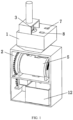
FIG. 1 is a schematic perspective view I of the present invention; -
FIG. 2 is a schematic perspective view II of the present invention; -
FIG. 3 is a front view of the present invention; -
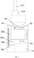
FIG. 4 is a cut view of the present invention; -
FIG. 5 is a schematic partial perspective view of the present invention; -
FIG. 6 is a cut view of the present invention ofFIG. 5 ; -
FIG. 7 is a cut view along line A-A of the present invention ofFIG. 6 ; -
FIG. 8 is a schematic partial perspective cut view of the present invention; -
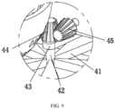
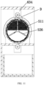
FIG. 9 is an enlarged view of portion B ofFIG. 8 of the present invention; -
FIG. 10 is a partial cut view of the present invention; -
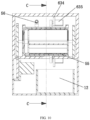
FIG. 11 is a cut view along line C-C of the present invention ofFIG. 10 ; and -
FIG. 12 is an enlarged view of portion D ofFIG. 11 of the present invention. - 1, top box; 2, support frame platform; 3, processing mechanism; 31, lifting assembly; 311, driving cylinder; 312, mounting plate; 313, connecting plate; 314, driving motor; 315, hemispherical grinding body; 32, material storage assembly; 321, material storage guide box; 322, rotating plate; 323, rotating motor; 33, filter screen; 4, agitation mechanism; 41, rotating blade; 42, connecting shaft; 43, connecting seat; 44, driven bevel gear; 45, driving bevel gear; 46, stepping motor; 5, receiving mechanism; 51, outer cylinder; 511, exhaust mesh; 52, transmission assembly; 521, L-shaped plate; 522, driving toothed disc; 523, transmission motor; 524, driven toothed disc; 525, transmission shaft; 526, rotary vane; 53, inner cylinder; 54, bearing seat; 56, agent inlet pipe; 6, docking mechanism; 61, guide pipe; 62, control valve; 63, upper control assembly; 631, arc-shaped plate; 632, boss; 633, guide wheel; 634, bearing plate; 635, linkage motor; 636, linkage block; 64, lower control assembly; 7, first material discharge cavity; 8, second material discharge cavity; 9, third material discharge cavity; 10, fourth material discharge cavity; 11, partition frame; 12, collection box; and 13, door panel.
- The following provides a detailed explanation of the present invention. The technical solutions in the embodiments of the present invention will be described clearly and completely. Obviously, the described embodiments are only a part of the embodiments of the present invention, rather than all the embodiments. The present invention is defined by the appended claims.
- Disclosed in this example is an aerogel thermal insulation mortar for a high temperature kiln, the material being prepared using the apparatus of
claim 1. The material has a composite aerogel thermal conductivity (average temperature 25°C) of 0.022-0.029 W/m•K, a thermal conductivity (average temperature 300°C) of 0.042-0.050 W/m•K, and a thermal conductivity (average temperature 800°C) of 0.078-0.085 W/m•K, and the specific preparation process is as follows: firstly preparing a saturated aluminum chloride hexahydrate (AlCl3•6H2O) solution, uniformly mixing AlCl3•6H2O, TEOS, anhydrous ethanol and deionized water in a molar ratio of 8-10: 1: 16-20: 16-20, stirring at normal temperature for 60 minutes, then according to TEOS and propylene oxide (P0) in a molar ratio of 1: 9-12, adding propylene oxide and stirring for 5-10 minutes, stopping the stirring after the solution changes color, and standing at room temperature to obtain a composite alcohol gel; and aging the alcohol gel in constant temperature water bath at 50°C for 24 hours using anhydrous ethanol as aging solution, and performing supercritical drying to obtain the Al2O3-SiO2 composite aerogel. - As shown in
FIGs. 1-12 , this example discloses equipment for preparing an aerogel thermal insulation mortar for a high-temperature kiln, including atop box 1, a support frame platform 2, aprocessing mechanism 3, an agitation mechanism 4, areceiving mechanism 5 and adocking mechanism 6. Thetop box 1 is mounted on the top of the support frame platform 2. Thetop box 1 is provided with apartition frame 11 capable of respectively dividing an inner space thereof into a firstmaterial discharge cavity 7, a secondmaterial discharge cavity 8, a thirdmaterial discharge cavity 9 and a fourthmaterial discharge cavity 10. Theprocessing mechanism 3 is provided on the top of thetop box 1 and the bottom of theprocessing mechanism 3 is provided in thetop box 1. The agitation mechanism 4 is mounted on thepartition frame 11 and is located at an inner bottom of thetop box 1. Thereceiving mechanism 5 is mounted on an inner top of the support frame platform 2 and docked with thetop box 1. Thedocking mechanism 6 is mounted on thereceiving mechanism 5. An inner bottom of the support frame platform 2 is provided with acollection box 12 docked with thereceiving mechanism 5. One side of thetop box 1 is provided with adoor panel 13. - Specifically, the
processing mechanism 3 includes a liftingassembly 31, amaterial storage assembly 32, and afilter screen 33. The liftingassembly 31 is mounted at the top of thetop box 1. Thematerial storage assembly 32 is arranged at an inner top of the thirdmaterial discharge cavity 9 and is docked with thefilter screen 33. Thefilter screen 33 is of a semi-spherical structure and is slidably mounted on a side wall of thepartition frame 11. Thefilter screen 33 is located in the fourthmaterial discharge cavity 10. Each raw material in the first stage of the aerogel powder can be automatically dropped and ground by means of the cooperation between thematerial storage assembly 32, the liftingassembly 31, and thefilter screen 33. The mixing efficiency and effect between subsequent raw materials are improved, wherein thedoor panel 13 of the side wall of thetop box 1 and thefilter screen 33 are slidably mounted on the side wall of thepartition frame 11, and thefilter screen 33 can be periodically cleaned to prevent the occurrence of clogging. - Specifically, the lifting
assembly 31 includes adriving cylinder 311, a mountingplate 312, a connectingplate 313, a drivingmotor 314, and a hemisphericalgrinding body 315. The mountingplate 312 is fixed on the top of thetop box 1. The drivingcylinder 311 is fixed on the top of the mountingplate 312. The top of the mountingplate 312 is connected to an output end of the drivingcylinder 311. The drivingmotor 314 is fixed on the connectingplate 313; an output end of the drivingmotor 314 is connected to the top of the hemisphericalgrinding body 315. When thematerial storage assembly 32 works, the material to be ground falls into thefilter screen 33. The drivingcylinder 311 drives the drivingmotor 314 on the connectingplate 313 to move downwards, and the drivingmotor 314 drives the hemisphericalgrinding body 315 connected to an output end thereof to rotate, and then the raw materials are mixed, and fall from a mesh of thefilter screen 33 to the inner bottom of thetop box 1 to complete the automatic mixing of the raw materials, so as to improve the mixing efficiency and effect of the subsequent aerogel without manual operation. - Specifically, the
material storage assembly 32 includes a materialstorage guide box 321, arotating plate 322, and arotating motor 323. The top of thetop box 1 is provided with a material port in communication with the materialstorage guide box 321. One side of the materialstorage guide box 321 is provided with a docking port. Therotating plate 322 is rotatably arranged at the docking port. Therotating motor 323 is mounted on one side wall of the materialstorage guide box 321. An output end of therotating motor 323 is connected to therotating plate 322. Therotating motor 323 drives therotating plate 322 to rotate so as to open the docking port, so that the obtained raw materials located in the materialstorage guide box 321 falls from therotating plate 322 into thefilter screen 33, and the step of automatically loading the raw materials to be mixed is completed. - Specifically, the agitation mechanism 4 includes a
rotating blade 41, a connectingshaft 42, a connectingseat 43, a drivenbevel gear 44, a drivingbevel gear 45, and a steppingmotor 46. The steppingmotor 46 is located in the thirdmaterial discharge cavity 9 and is fixed on thepartition frame 11. The drivingbevel gear 45 is located in the fourthmaterial discharge cavity 10 and is connected to an output end of the steppingmotor 46. The drivenbevel gear 44 is fixed on the top end of the connectingshaft 42. The drivenbevel gear 44 meshes with the drivingbevel gear 45. Therotating blade 41 is fixed at a bottom end of the connectingshaft 42. The drivingbevel gear 45 connected to an output end thereof is driven to rotate by the steppingmotor 46, the drivenbevel gear 44 meshing with the drivingbevel gear 45 is driven to rotate, and the connectingshaft 42 connected to the drivenbevel gear 44 and therotating blade 41 are synchronously rotated at any time, so that each raw material located in the inner bottom of thetop box 1 is fully mixed, and an aerogel thermal insulation mortar is obtained. - Specifically, the
transmission assembly 52 includes an L-shapedplate 521, a drivingtoothed disc 522, atransmission motor 523, a driventoothed disc 524 and atransmission shaft 525. The L-shapedplate 521 is fixed on an inner side wall of the support frame platform 2. Thetransmission motor 523 is fixed on the L-shapedplate 521 and an output end of thetransmission motor 523 is connected to the drivingtoothed disc 522. Thetransmission shaft 525 is rotatably arranged on theouter cylinder 51. One end of thetransmission shaft 525 is connected to the driventoothed disc 524. The driventoothed disc 524 meshes with the drivingtoothed disc 522. Arotary vane 526 is provided on thetransmission shaft 525; one end of therotary vane 526 is in contact with an inner side wall of theinner cylinder 53. Both ends of theouter cylinder 51 are provided with anexhaust mesh 511. Both theouter cylinder 51 and theinner cylinder 53 are provided with an upper inlet and a lower outlet. Thetransmission motor 523 drives the drivingtoothed disc 522 connected with output end thereof to rotate, which brings the driventoothed disc 524 engaged with the drivingtoothed disc 522 to rotate. Then therotary vanes 526 on thetransmission shaft 525 rotate synchronously so that the aerogel thermal insulation mortar located in theinner cylinder 53 can be mixed and flow, improving the mixing efficiency and effect. Theexhaust mesh 511 arranged at both ends of theouter cylinder 51 can discharge the gas generated during the production of aerogel thermal insulation mortar. Thedocking mechanism 6 can realize the automatic opening and closing control of the upper inlet and the lower outlet. - Specifically, the
docking mechanism 6 includes aguide pipe 61, acontrol valve 62, anupper control assembly 63 and alower control assembly 64. Two ends of theguide pipe 61 are respectively in communication with thetop box 1 and the upper inlet. Thecontrol valve 62 is fixed on theguide pipe 61. Theupper control assembly 63 andlower control assembly 64 have the same structure. Theupper control assembly 63 is fixed on an inner top of the support frame platform 2 and cooperates with the upper inlet, and thelower control assembly 64 is fixed on the support frame platform 2 and cooperates with the lower outlet. Theguide pipe 61 is controlled to open by thecontrol valve 62. Theupper control assembly 63 works to control the opening of the upper inlet, so that the aerogel thermal insulation mortar enters theinner cylinder 53 from theguide pipe 61, and then thelower control assembly 64 controls the opening and closing of the lower outlet to complete the automatic loading of the aerogel thermal insulation mortar. - Specifically, the
upper control assembly 63 includes an arc-shapedplate 631, aboss 632, aguide wheel 633, abearing plate 634 and alinkage motor 635. The arc-shapedplate 631 is arranged in theinner cylinder 53. Theboss 632 is fixed on an outer side wall of the arc-shapedplate 631. The bearingplate 634 is fixed on the support frame platform 2. Thelinkage motor 635 is fixed on thebearing plate 634 and an output end of thelinkage motor 635 is connected to theguide wheel 633. The outer side wall of theguide wheel 633 is provided with alinkage block 636 connected thereto, and one end of thelinkage block 636 is connected to theboss 632. Thelinkage motor 635 drives theguide wheel 633 connected to an output end thereof and thelinkage block 636 fixed on theguide wheel 633 to rotate, thereby driving theboss 632 and the arc-shapedplate 631 connected to one end of thelinkage block 636 to rotate in theinner cylinder 53, thereby achieving the automatic opening and closing control of the upper inlet and the lower outlet on theinner cylinder 53 without manual operation, improving the production efficiency of the aerogel thermal insulation mortar. The equipment has strong overall adaptability. - According to the present invention, provided is a process for preparing an aerogel insulation material for a high temperature kiln using the aforementioned apparatus, the process including the steps:
- S1, feeding an adhesive, an aerogel powder, a reinforcing agent, and a liquid solvent to the inner bottom of the
top box 1 from the firstmaterial discharge cavity 7 and the secondmaterial discharge cavity 8 respectively, at the same time, 323 driving, via the rotating motor, therotating plate 322 to rotate and open the docking port, so that the obtained polyphenyl particles located in the materialstorage guide box 321 fall from therotating plate 322 into thefilter screen 33, and secondly, driving, via thedriving cylinder 311, the drivingmotor 314 on the connectingplate 313 to move downwards; and driving, via the drivingmotor 314, the hemisphericalgrinding body 315 connected to an output end thereof to rotate, and then grinding the polyphenyl particles, which then falls from a mesh of thefilter screen 33 to the inner bottom of thetop box 1; - S2, driving, via the stepping
motor 46, the drivingbevel gear 45 connected to an output end thereof to rotate, driving the drivenbevel gear 44 meshing with the drivingbevel gear 45 to rotate, and synchronously rotating the connectingshaft 42 connected to the drivenbevel gear 44 and therotating blade 41 at any time, to fully mix each raw material located in the inner bottom of thetop box 1 and obtain an aerogel thermal insulation mortar; - S3, controlling, via the
control valve 62, theguide pipe 61 to open, and controlling, via theupper control assembly 63, the upper inlet to open, so that the aerogel thermal insulation mortar enters theinner cylinder 53 from theguide pipe 61, and the exhaust meshes 511 provided at the two ends of theouter cylinder 51 are capable of discharging the gas during the production process of the aerogel thermal insulation mortar; - S4, driving, via the
transmission motor 523, the drivingtoothed disc 522 connected to an output end thereof to rotate, driving the driventoothed disc 524 engaged with the drivingtoothed disc 522 to rotate, and in turn, therotary vane 526 on thetransmission shaft 525 to rotate synchronously, so as to mix and flow the aerogel thermal insulation mortar located in theinner cylinder 53, improving the mixing efficiency and effect thereof; and - S5, when the mixing of the aerogel thermal insulation mortar is completed, controlling, via the
lower control assembly 64, the lower outlet to be open, so that the aerogel enters thecollection box 12 from the lower outlet, and the whole preparation and collection operation of the aerogel thermal insulation mortar is completed. - The previous description of the disclosed embodiments is provided to enable any person skilled in the art to make or use the present invention. Various modifications to these embodiments will be readily apparent to those skilled in the art, and the generic principles defined herein may be implemented in other embodiments. Thus, the present invention is not intended to be limited to the embodiments shown herein but is defined by the appended claims.
Claims (2)
- An apparatus for preparing an aerogel thermal insulation mortar for a high-temperature kiln, comprising a top box (1), a support frame platform (2), a processing mechanism (3), an agitation mechanism (4), a receiving mechanism (5) and a docking mechanism (6), characterized in that the top box (1) is mounted on the top of the support frame platform (2); the top box (1) is provided with a partition frame (11) capable of respectively dividing an inner space thereof into a first material discharge cavity (7), a second material discharge cavity (8), a third material discharge cavity (9) and a fourth material discharge cavity (10); the processing mechanism (3) is provided on the top of the top box (1) and the bottom of the processing mechanism (3) is provided in the top box (1); the agitation mechanism (4) is mounted on the partition frame (11) and is located at an inner bottom of the top box (1); the receiving mechanism (5) is mounted on an inner top of the support frame platform (2) and docked with the top box (1); the docking mechanism (6) is mounted on the receiving mechanism (5); the inner bottom of the support frame platform (2) is provided with a collection box (12) docked with the receiving mechanism (5); and one side of the top box (1) is provided with a door panel (13); the processing mechanism (3) comprises a lifting assembly (31), a material storage assembly (32) and a filter screen (33), wherein the lifting assembly (31) is mounted at the top of the top box (1); the material storage assembly (32) is arranged at an inner top of the third material discharge cavity (9) and is docked with the filter screen (33); the filter screen (33) is of a semi-spherical structure and is slidably mounted on a side wall of the partition frame (11); and the filter screen (33) is located in the fourth material discharge cavity (10); the lifting assembly (31) comprises a driving cylinder (311), a mounting plate (312), a connecting plate (313), a driving motor (314) and a hemispherical grinding body (315), wherein the mounting plate (312) is fixed on the top of the top box (1); the driving cylinder (311) is fixed on the top of the mounting plate (312); the top of the mounting plate (312) is connected to an output end of the driving cylinder (311); the driving motor (314) is fixed on the connecting plate (313); and an output end of the driving motor (314) is connected to the top of the hemispherical grinding body (315); the material storage assembly (32) comprises a material storage guide box (321), a rotating plate (322) and a rotating motor (323), wherein the top of the top box (1) is provided with a material port in communication with the material storage guide box (321); one side of the material storage guide box (321) is provided with a docking port; the rotating plate (322) is rotatably arranged at the docking port; the rotating motor (323) is mounted on one side wall of the material storage guide box (321); and an output end of the rotating motor (323) is connected to the rotating plate (322); the agitation mechanism (4) comprises a rotating blade (41), a connecting shaft (42), a connecting seat (43), a driven bevel gear (44), a driving bevel gear (45) and a stepping motor (46), wherein the stepping motor (46) is located in the third material discharge cavity (9) and is fixed on the partition frame(11); the driving bevel gear (45) is located in the fourth material discharge cavity (10) and is connected to an output end of the stepping motor (46); the driven bevel gear (44) is fixed on the top end of the connecting shaft (42); the driven bevel gear (44) meshes with the driving bevel gear (45); and the rotating blade (41) is fixed at a bottom end of the connecting shaft (42); the receiving mechanism (5) comprises an outer cylinder (51), a transmission assembly (52), an inner cylinder (53) and two bearing seats (54), wherein the two bearing seats (54) are mounted on the support frame platform (2) at intervals; the transmission assembly (52) is fixed on the support frame platform (2) and extends to the inner cylinder (53) for arrangement; two ends of the outer cylinder (51) are respectively connected to the two bearing seats (54); the inner cylinder (53) is arranged within the outer cylinder (51); the inner cylinder (53) is of a hollow structure; and an outer side wall of the outer cylinder (51) is provided with an agent inlet pipe (56) in communication with the inner cylinder (53); the transmission assembly (52) comprises an L-shaped plate (521), a driving toothed disc (522), a transmission motor (523), a driven toothed disc (524) and a transmission shaft (525), wherein the L-shaped plate (521) is fixed on an inner side wall of the support frame platform (2); the transmission motor (523) is fixed on the L-shaped plate (521) and an output end of the transmission motor (523) is connected to the driving toothed disc (522); the transmission shaft (525) is rotatably arranged on the outer cylinder (51); one end of the transmission shaft (525) is connected to the driven toothed disc (524); the driven toothed disc (524) meshes with the driving toothed disc (522); a rotary vane (526) is provided on the transmission shaft (525); one end of the rotary vane (526) is in contact with an inner side wall of the inner cylinder (53); both ends of the outer cylinder (51) are provided with an exhaust mesh (511); and both the outer cylinder (51) and the inner cylinder (53) are provided with an upper inlet and a lower outlet; the docking mechanism (6) comprises a guide pipe (61), a control valve (62), an upper control assembly (63) and a lower control assembly (64), wherein two ends of the guide pipe (61) are respectively in communication with the top box (1) and the upper inlet; the control valve (62) is fixed on the guide pipe (61); the upper control assembly (63) and lower control assembly (64) have the same structure; and the upper control assembly (63) is fixed on an inner top of the support frame platform (2) and cooperates with the upper inlet, and the lower control assembly (64) is fixed on the support frame platform (2) and cooperates with the lower outlet; the upper control assembly (63) comprises an arc-shaped plate (631), a boss (632), a guide wheel (633), a bearing plate (634) and a linkage motor (635), wherein the arc-shaped plate (631) is arranged in the inner cylinder (53); the boss (632) is fixed on an outer side wall of the arc-shaped plate (631); the bearing plate (634) is fixed on the support frame platform (2); the linkage motor (635) is fixed on the bearing plate (634) and an output end of the linkage motor (635) is connected to the guide wheel (633); and an outer side wall of the guide wheel (633) is provided with a linkage block (636) connected thereto and one end of the linkage block (636) is connected to the boss (632).
- A process for preparing an aerogel thermal insulation mortar for a high-temperature kiln using the apparatus of claim 1, further comprising the following steps:S1, feeding an adhesive, an aerogel powder, a reinforcing agent, and a liquid solvent to the inner bottom of the top box (1) from the first material discharge cavity (7) and the second material discharge cavity (8) respectively, at the same time, (323) driving, via the rotating motor, the rotating plate (322) to rotate and open the docking port, so that the obtained polyphenyl particles located in the material storage guide box (321) fall from the rotating plate (322) into the filter screen (33), and secondly, driving, via the driving cylinder (311), the driving motor (314) on the connecting plate (313) to move downwards; and driving, via the driving motor (314), the hemispherical grinding body (315) connected to an output end thereof to rotate, and then grinding the polyphenyl particles, which then falls from a mesh of the filter screen (33) to the inner bottom of the top box (1);S2, driving, via the stepping motor (46), the driving bevel gear (45) connected to an output end thereof to rotate, driving the driven bevel gear (44) meshing with the driving bevel gear (45) to rotate, and synchronously rotating the connecting shaft (42) connected to the driven bevel gear (44) and the rotating blade (41) at any time, to fully mix each raw material located in the inner bottom of the top box (1) and obtain an aerogel thermal insulation mortar;S3, controlling, via the control valve (62), the guide pipe (61) to open, and controlling, via the upper control assembly (63), the upper inlet to open, so that the aerogel thermal insulation mortar enters the inner cylinder (53) from the guide pipe (61), and the exhaust meshes (511) provided at the two ends of the outer cylinder (51) are capable of discharging the gas during the production process of the aerogel thermal insulation mortar;S4, driving, via the transmission motor (523), the driving toothed disc (522) connected to an output end thereof to rotate, driving the driven toothed disc (524) engaged with the driving toothed disc (522) to rotate, and in turn, the rotary vane (526) on the transmission shaft (525) to rotate synchronously, so as to mix and flow the aerogel thermal insulation mortar located in the inner cylinder (53), improving the mixing efficiency and effect thereof; andS5, when the mixing of the aerogel thermal insulation mortar is completed, controlling, via the lower control assembly (64), the lower outlet to be open, so that the aerogel enters the collection box (12) from the lower outlet, and the whole preparation and collection operation of the aerogel thermal insulation mortar is completed.
Applications Claiming Priority (1)
| Application Number | Priority Date | Filing Date | Title |
|---|---|---|---|
| CN202211247800.4A CN115847610B (en) | 2022-10-12 | 2022-10-12 | Aerogel thermal insulation mortar preparation equipment for high-temperature kiln and method thereof |
Publications (3)
| Publication Number | Publication Date |
|---|---|
| EP4353348A2 EP4353348A2 (en) | 2024-04-17 |
| EP4353348A3 EP4353348A3 (en) | 2024-07-03 |
| EP4353348B1 true EP4353348B1 (en) | 2025-03-26 |
Family
ID=85661470
Family Applications (1)
| Application Number | Title | Priority Date | Filing Date |
|---|---|---|---|
| EP23192311.1A Active EP4353348B1 (en) | 2022-10-12 | 2023-08-21 | Apparatus and method for preparing aerogel thermal insulation mortar for high temperature kiln |
Country Status (4)
| Country | Link |
|---|---|
| US (1) | US11970424B1 (en) |
| EP (1) | EP4353348B1 (en) |
| JP (1) | JP7384342B1 (en) |
| CN (1) | CN115847610B (en) |
Families Citing this family (13)
| Publication number | Priority date | Publication date | Assignee | Title |
|---|---|---|---|---|
| CN117258605B (en) * | 2023-11-22 | 2024-02-06 | 山东天利机械制造有限公司 | Pulp raw material treatment stirring device and method thereof |
| CN117380067B (en) * | 2023-12-12 | 2024-03-12 | 中国热带农业科学院农业机械研究所 | Pineapple She Yuzhi feed mixing equipment |
| CN117644027B (en) * | 2024-01-30 | 2024-04-09 | 云南凯瑞特工程机械设备有限公司 | Portable sand material screening device who carries on |
| CN118145851A (en) * | 2024-05-10 | 2024-06-07 | 国家海洋局北海预报中心((国家海洋局青岛海洋预报台)(国家海洋局青岛海洋环境监测中心站)) | Laboratory wastewater treatment equipment and method |
| CN118357039B (en) * | 2024-05-20 | 2026-02-06 | 江苏晶盛旺新材料科技有限公司 | Superfine silica micropowder apparatus for producing for high strength electric arc quartz crucible |
| CN118253113B (en) * | 2024-05-31 | 2024-10-18 | 江苏思派新能源科技有限公司 | Lithium battery electrolyte solvent preparation device |
| CN118528480B (en) * | 2024-07-18 | 2024-10-29 | 江苏友顺节能科技有限公司 | A prefabricated device for producing building exterior wall insulation boards |
| CN118721423B (en) * | 2024-08-05 | 2025-06-06 | 天津长森环保科技有限公司 | Equipment for preparing wall heat-insulating mortar by using mine tailing fine sand |
| CN118634706B (en) * | 2024-08-13 | 2025-01-03 | 山东锐朗生态肥业有限公司 | Mixing device for rooting, soil adjustment and fertilizer processing and preparation |
| CN118988570B (en) * | 2024-10-21 | 2025-01-03 | 金堆城钼业汝阳有限责任公司 | Molybdenum ore flotation equipment and process |
| CN118988108B (en) * | 2024-10-25 | 2025-01-17 | 定远诚宇电工材料有限公司 | An integrated production equipment for polyurethane insulating varnish |
| CN119407956B (en) * | 2024-11-15 | 2025-05-16 | 山东质能新型材料有限公司 | Batching feeding device for inorganic gel dry-mixed mortar production |
| CN119688966B (en) * | 2024-12-09 | 2025-11-11 | 江苏乐通彩业科技发展有限公司 | Gypsum mortar detection device and application method thereof |
Family Cites Families (34)
| Publication number | Priority date | Publication date | Assignee | Title |
|---|---|---|---|---|
| DE4008084A1 (en) * | 1990-03-14 | 1991-09-19 | Pro Mineral Ges | METHOD FOR PRODUCING PLASTER PANELS, ESPECIALLY OF FLOOR PLATES |
| CN101450852A (en) * | 2008-11-27 | 2009-06-10 | 长沙星纳气凝胶有限公司 | Nano-pore SiO2 aerogel thermal insulation composite material and preparation method thereof |
| CN101445356A (en) * | 2008-11-27 | 2009-06-03 | 中南大学 | Nano-hole aerogel heat-insulating composite material and preparation method thereof |
| CN101851063B (en) * | 2010-05-21 | 2012-05-02 | 郑州大学 | Technology of preparing glass-ceramic from blast furnace slag and fly ash |
| JP6029833B2 (en) * | 2012-02-28 | 2016-11-24 | ホソカワミクロン株式会社 | Powder processing equipment |
| JP5895625B2 (en) * | 2012-03-15 | 2016-03-30 | 宇部興産株式会社 | Mortar construction method |
| WO2014153570A2 (en) * | 2013-03-15 | 2014-09-25 | Transtar Group, Ltd | New and improved system for processing various chemicals and materials |
| US20160238279A1 (en) * | 2015-02-13 | 2016-08-18 | Corning Incorporated | Methods of processing a furnace |
| US20180369828A1 (en) * | 2017-06-22 | 2018-12-27 | Marc Vanderbeken | Method and Apparatus for separating organics from a contaminated organics-inorganics waste stream |
| CN108579983A (en) * | 2018-03-13 | 2018-09-28 | 王少平 | A kind of integrated breaking milling apparatus of cement raw material |
| CN108437206A (en) * | 2018-04-02 | 2018-08-24 | 成都亚联科科技有限公司 | A kind of building mortar breaker |
| KR101992351B1 (en) * | 2018-05-31 | 2019-06-25 | 주식회사 서문기술 | Mortar composition mixing apparatus and method for recovering a section of concrete using the same |
| CN209613098U (en) * | 2018-11-21 | 2019-11-12 | 太仓宝祥有色金属制品厂 | A kind of metalliferous ore waste residue grinding screening plant that convenience is filtered metal |
| CN111823655A (en) * | 2019-04-15 | 2020-10-27 | 江苏泛亚微透科技股份有限公司 | Composite material laminated by attaching silicon dioxide aerogel flexible elastic heat insulation material and ePTFE (expanded polyethylene) membrane as well as preparation method and application thereof |
| CN110201780A (en) * | 2019-06-19 | 2019-09-06 | 吴玉华 | A kind of processing of farm products black rice crushing grinding device |
| CN211967949U (en) * | 2019-11-29 | 2020-11-20 | 南京港港务工程有限公司 | Automatic blending device is used in interlocking piece production |
| CN211886839U (en) * | 2020-03-31 | 2020-11-10 | 刘光国 | A equipment for preparing aerogel combined material |
| CN212580178U (en) * | 2020-07-01 | 2021-02-23 | 惠州市富兴隆生物科技有限公司 | Particle filling machine |
| CN112430058A (en) * | 2020-10-27 | 2021-03-02 | 青海爱能森新材料科技有限公司 | Magnesium-based heat-insulating fireproof material for buildings and preparation method thereof |
| CN213829623U (en) * | 2020-11-04 | 2021-07-30 | 涉县清漳水泥制造有限公司 | Stirring device for dry-mixed mortar tank |
| CN112619803B (en) * | 2021-01-12 | 2022-04-29 | 辽宁银盛水泥集团有限公司 | Grinding equipment for cement clinker production |
| CN113103406B (en) * | 2021-03-04 | 2022-10-11 | 安徽致和节能科技有限公司 | Processing technology of outer wall homogeneous modified fireproof insulation board |
| CN113043468A (en) * | 2021-03-18 | 2021-06-29 | 利辛县泉鑫新型建材有限公司 | Premixed mortar production system |
| CN215196689U (en) * | 2021-04-28 | 2021-12-17 | 上海乐宝日化股份有限公司 | Batching device for producing and processing washing products |
| CN215150386U (en) * | 2021-05-17 | 2021-12-14 | 河南省鼎峰建材有限公司 | Environment-friendly ready-mixed mortar production facility |
| CN113427636A (en) * | 2021-07-27 | 2021-09-24 | 江先庆 | Building concrete gravel mixing equipment |
| CN113856341A (en) * | 2021-09-28 | 2021-12-31 | 南宁利亚德环保科技有限公司 | Receive material formula dust remover |
| CN216396241U (en) * | 2021-11-22 | 2022-04-29 | 佛山典案软装工程有限公司 | Sample color sample proportioning device for soft mounting design |
| CN114290522A (en) * | 2021-12-20 | 2022-04-08 | 毕道广 | Concrete pouring forming device for building construction and using method thereof |
| CN217249141U (en) * | 2021-12-21 | 2022-08-23 | 沈阳金象广禾绿源农业科技有限公司 | Automatic grinding equipment for organic fertilizer production |
| CN114479535B (en) * | 2022-01-20 | 2023-01-20 | 中建材科创新技术研究院(山东)有限公司 | High-temperature aerogel thermal insulation coating, preparation equipment and use method thereof |
| CN217597431U (en) * | 2022-01-27 | 2022-10-18 | 江西千泰建材有限公司 | A high-stable storage device for thermal insulation mortar |
| CN217248214U (en) * | 2022-04-01 | 2022-08-23 | 江苏金裕粮元现代农业发展有限公司 | Stirring device for food production and processing |
| CN115229958A (en) * | 2022-07-21 | 2022-10-25 | 王洪运 | Preparation method of geopolymer-based water permeable brick |
-
2022
- 2022-10-12 CN CN202211247800.4A patent/CN115847610B/en active Active
-
2023
- 2023-08-21 EP EP23192311.1A patent/EP4353348B1/en active Active
- 2023-08-21 US US18/453,104 patent/US11970424B1/en active Active
- 2023-08-23 JP JP2023135683A patent/JP7384342B1/en active Active
Also Published As
| Publication number | Publication date |
|---|---|
| JP2024057578A (en) | 2024-04-24 |
| US11970424B1 (en) | 2024-04-30 |
| EP4353348A2 (en) | 2024-04-17 |
| US20240124354A1 (en) | 2024-04-18 |
| JP7384342B1 (en) | 2023-11-21 |
| CN115847610A (en) | 2023-03-28 |
| EP4353348A3 (en) | 2024-07-03 |
| CN115847610B (en) | 2023-07-11 |
Similar Documents
| Publication | Publication Date | Title |
|---|---|---|
| US11970424B1 (en) | Equipment and method for preparing aerogel thermal insulation mortar for high temperature kiln | |
| CN114479535B (en) | High-temperature aerogel thermal insulation coating, preparation equipment and use method thereof | |
| CN106215793B (en) | A kind of ultrasonic wave mixing vacuum stirring tank for natural esters insulating oil | |
| CN113457523A (en) | Material multi-angle stirring mixing arrangement for construction | |
| CN218393367U (en) | Mixing mechanism for preparing heat insulation coating | |
| CN103921354A (en) | Foam concrete stirring device | |
| CN211030611U (en) | Agitated vessel is used in concrete preparation that permeates water | |
| CN116272799A (en) | Preparation method of graphene silicon dioxide composite aerogel | |
| CN113894958A (en) | Polyethylene particle system and method thereof | |
| CN222239789U (en) | High-efficient waste liquid treatment stirred tank | |
| CN211415679U (en) | Blank mixing device for ceramic production | |
| RU2842944C2 (en) | Aerogel heat-insulation solution preparation equipment and method, aerogel solution for high-temperature furnace | |
| CN215276921U (en) | Dispersion devices for preparing degradable porous biological membrane | |
| CN113019205B (en) | Strontium titanate superfine powder preparation equipment | |
| CN214051461U (en) | Energy-conserving building materials are made and are used compounding device | |
| CN210116105U (en) | Polystyrene granule prefoaming tank | |
| CN209205210U (en) | It is a kind of for manufacture it is black back grid advertising cloth blender | |
| CN215086860U (en) | A raw material proportioning device for the production of compound thickener | |
| CN220720068U (en) | High-pressure foaming device capable of automatically discharging for production of electric vehicle seat cushion | |
| CN217703970U (en) | A special mortar mixer with adjustable angle | |
| CN220297398U (en) | Foaming device for concrete foaming agent | |
| CN217341089U (en) | Low-speed stirring device for preparing nano ink-jet color paste | |
| CN222710747U (en) | A high-efficiency rotor sand mixer with fast mixing for foundry workshops | |
| CN219583213U (en) | Cement mixer with intelligent control function | |
| CN216825702U (en) | A kind of mixing equipment for waterproof coating production |
Legal Events
| Date | Code | Title | Description |
|---|---|---|---|
| PUAI | Public reference made under article 153(3) epc to a published international application that has entered the european phase |
Free format text: ORIGINAL CODE: 0009012 |
|
| STAA | Information on the status of an ep patent application or granted ep patent |
Free format text: STATUS: REQUEST FOR EXAMINATION WAS MADE |
|
| 17P | Request for examination filed |
Effective date: 20230821 |
|
| AK | Designated contracting states |
Kind code of ref document: A2 Designated state(s): AL AT BE BG CH CY CZ DE DK EE ES FI FR GB GR HR HU IE IS IT LI LT LU LV MC ME MK MT NL NO PL PT RO RS SE SI SK SM TR |
|
| PUAL | Search report despatched |
Free format text: ORIGINAL CODE: 0009013 |
|
| STAA | Information on the status of an ep patent application or granted ep patent |
Free format text: STATUS: EXAMINATION IS IN PROGRESS |
|
| AK | Designated contracting states |
Kind code of ref document: A3 Designated state(s): AL AT BE BG CH CY CZ DE DK EE ES FI FR GB GR HR HU IE IS IT LI LT LU LV MC ME MK MT NL NO PL PT RO RS SE SI SK SM TR |
|
| RIC1 | Information provided on ipc code assigned before grant |
Ipc: C09D 1/04 20060101ALI20240524BHEP Ipc: B01F 33/82 20220101ALI20240524BHEP Ipc: B01F 27/90 20220101ALI20240524BHEP Ipc: B01F 27/70 20220101ALI20240524BHEP Ipc: B01F 27/091 20220101ALI20240524BHEP Ipc: B01F 23/80 20220101ALI20240524BHEP Ipc: B01F 23/70 20220101ALI20240524BHEP Ipc: B01F 23/53 20220101AFI20240524BHEP |
|
| 17Q | First examination report despatched |
Effective date: 20240612 |
|
| RIC1 | Information provided on ipc code assigned before grant |
Ipc: C09D 1/04 20060101ALI20240820BHEP Ipc: B01F 33/82 20220101ALI20240820BHEP Ipc: B01F 27/90 20220101ALI20240820BHEP Ipc: B01F 27/70 20220101ALI20240820BHEP Ipc: B01F 27/091 20220101ALI20240820BHEP Ipc: B01F 23/80 20220101ALI20240820BHEP Ipc: B01F 23/70 20220101ALI20240820BHEP Ipc: B01F 23/53 20220101AFI20240820BHEP |
|
| GRAP | Despatch of communication of intention to grant a patent |
Free format text: ORIGINAL CODE: EPIDOSNIGR1 |
|
| STAA | Information on the status of an ep patent application or granted ep patent |
Free format text: STATUS: GRANT OF PATENT IS INTENDED |
|
| INTG | Intention to grant announced |
Effective date: 20241011 |
|
| GRAS | Grant fee paid |
Free format text: ORIGINAL CODE: EPIDOSNIGR3 |
|
| GRAA | (expected) grant |
Free format text: ORIGINAL CODE: 0009210 |
|
| STAA | Information on the status of an ep patent application or granted ep patent |
Free format text: STATUS: THE PATENT HAS BEEN GRANTED |
|
| AK | Designated contracting states |
Kind code of ref document: B1 Designated state(s): AL AT BE BG CH CY CZ DE DK EE ES FI FR GB GR HR HU IE IS IT LI LT LU LV MC ME MK MT NL NO PL PT RO RS SE SI SK SM TR |
|
| REG | Reference to a national code |
Ref country code: GB Ref legal event code: FG4D |
|
| RIN1 | Information on inventor provided before grant (corrected) |
Inventor name: ZHANG, FAN Inventor name: ZHOU, PENG Inventor name: YIN, XIAODONG Inventor name: ZHANG, RUI Inventor name: LIU, ZHENSEN Inventor name: GAO, XIPING Inventor name: XU, LEI Inventor name: FENG, GANG Inventor name: HE, KUN Inventor name: XIN, ZHIJUN Inventor name: WANG, MINGMING Inventor name: ZHANG, ZHONGLUN |
|
| REG | Reference to a national code |
Ref country code: CH Ref legal event code: EP |
|
| REG | Reference to a national code |
Ref country code: DE Ref legal event code: R096 Ref document number: 602023002581 Country of ref document: DE |
|
| REG | Reference to a national code |
Ref country code: IE Ref legal event code: FG4D |
|
| PG25 | Lapsed in a contracting state [announced via postgrant information from national office to epo] |
Ref country code: RS Free format text: LAPSE BECAUSE OF FAILURE TO SUBMIT A TRANSLATION OF THE DESCRIPTION OR TO PAY THE FEE WITHIN THE PRESCRIBED TIME-LIMIT Effective date: 20250626 |
|
| PG25 | Lapsed in a contracting state [announced via postgrant information from national office to epo] |
Ref country code: FI Free format text: LAPSE BECAUSE OF FAILURE TO SUBMIT A TRANSLATION OF THE DESCRIPTION OR TO PAY THE FEE WITHIN THE PRESCRIBED TIME-LIMIT Effective date: 20250326 |
|
| REG | Reference to a national code |
Ref country code: LT Ref legal event code: MG9D |
|
| PG25 | Lapsed in a contracting state [announced via postgrant information from national office to epo] |
Ref country code: NO Free format text: LAPSE BECAUSE OF FAILURE TO SUBMIT A TRANSLATION OF THE DESCRIPTION OR TO PAY THE FEE WITHIN THE PRESCRIBED TIME-LIMIT Effective date: 20250626 |
|
| PG25 | Lapsed in a contracting state [announced via postgrant information from national office to epo] |
Ref country code: HR Free format text: LAPSE BECAUSE OF FAILURE TO SUBMIT A TRANSLATION OF THE DESCRIPTION OR TO PAY THE FEE WITHIN THE PRESCRIBED TIME-LIMIT Effective date: 20250326 |
|
| PG25 | Lapsed in a contracting state [announced via postgrant information from national office to epo] |
Ref country code: LV Free format text: LAPSE BECAUSE OF FAILURE TO SUBMIT A TRANSLATION OF THE DESCRIPTION OR TO PAY THE FEE WITHIN THE PRESCRIBED TIME-LIMIT Effective date: 20250326 |
|
| PG25 | Lapsed in a contracting state [announced via postgrant information from national office to epo] |
Ref country code: GR Free format text: LAPSE BECAUSE OF FAILURE TO SUBMIT A TRANSLATION OF THE DESCRIPTION OR TO PAY THE FEE WITHIN THE PRESCRIBED TIME-LIMIT Effective date: 20250627 Ref country code: BG Free format text: LAPSE BECAUSE OF FAILURE TO SUBMIT A TRANSLATION OF THE DESCRIPTION OR TO PAY THE FEE WITHIN THE PRESCRIBED TIME-LIMIT Effective date: 20250326 |
|
| REG | Reference to a national code |
Ref country code: NL Ref legal event code: MP Effective date: 20250326 |
|
| PG25 | Lapsed in a contracting state [announced via postgrant information from national office to epo] |
Ref country code: NL Free format text: LAPSE BECAUSE OF FAILURE TO SUBMIT A TRANSLATION OF THE DESCRIPTION OR TO PAY THE FEE WITHIN THE PRESCRIBED TIME-LIMIT Effective date: 20250326 |
|
| PG25 | Lapsed in a contracting state [announced via postgrant information from national office to epo] |
Ref country code: SE Free format text: LAPSE BECAUSE OF FAILURE TO SUBMIT A TRANSLATION OF THE DESCRIPTION OR TO PAY THE FEE WITHIN THE PRESCRIBED TIME-LIMIT Effective date: 20250326 |
|
| REG | Reference to a national code |
Ref country code: AT Ref legal event code: MK05 Ref document number: 1778522 Country of ref document: AT Kind code of ref document: T Effective date: 20250326 |
|
| PG25 | Lapsed in a contracting state [announced via postgrant information from national office to epo] |
Ref country code: SM Free format text: LAPSE BECAUSE OF FAILURE TO SUBMIT A TRANSLATION OF THE DESCRIPTION OR TO PAY THE FEE WITHIN THE PRESCRIBED TIME-LIMIT Effective date: 20250326 |
|
| PG25 | Lapsed in a contracting state [announced via postgrant information from national office to epo] |
Ref country code: PT Free format text: LAPSE BECAUSE OF FAILURE TO SUBMIT A TRANSLATION OF THE DESCRIPTION OR TO PAY THE FEE WITHIN THE PRESCRIBED TIME-LIMIT Effective date: 20250728 Ref country code: ES Free format text: LAPSE BECAUSE OF FAILURE TO SUBMIT A TRANSLATION OF THE DESCRIPTION OR TO PAY THE FEE WITHIN THE PRESCRIBED TIME-LIMIT Effective date: 20250326 |
|
| PGFP | Annual fee paid to national office [announced via postgrant information from national office to epo] |
Ref country code: DE Payment date: 20250929 Year of fee payment: 3 |
|
| PG25 | Lapsed in a contracting state [announced via postgrant information from national office to epo] |
Ref country code: IT Free format text: LAPSE BECAUSE OF FAILURE TO SUBMIT A TRANSLATION OF THE DESCRIPTION OR TO PAY THE FEE WITHIN THE PRESCRIBED TIME-LIMIT Effective date: 20250326 Ref country code: PL Free format text: LAPSE BECAUSE OF FAILURE TO SUBMIT A TRANSLATION OF THE DESCRIPTION OR TO PAY THE FEE WITHIN THE PRESCRIBED TIME-LIMIT Effective date: 20250326 |
|
| PG25 | Lapsed in a contracting state [announced via postgrant information from national office to epo] |
Ref country code: AT Free format text: LAPSE BECAUSE OF FAILURE TO SUBMIT A TRANSLATION OF THE DESCRIPTION OR TO PAY THE FEE WITHIN THE PRESCRIBED TIME-LIMIT Effective date: 20250326 |
|
| PG25 | Lapsed in a contracting state [announced via postgrant information from national office to epo] |
Ref country code: EE Free format text: LAPSE BECAUSE OF FAILURE TO SUBMIT A TRANSLATION OF THE DESCRIPTION OR TO PAY THE FEE WITHIN THE PRESCRIBED TIME-LIMIT Effective date: 20250326 |
|
| PG25 | Lapsed in a contracting state [announced via postgrant information from national office to epo] |
Ref country code: SK Free format text: LAPSE BECAUSE OF FAILURE TO SUBMIT A TRANSLATION OF THE DESCRIPTION OR TO PAY THE FEE WITHIN THE PRESCRIBED TIME-LIMIT Effective date: 20250326 |
|
| PG25 | Lapsed in a contracting state [announced via postgrant information from national office to epo] |
Ref country code: IS Free format text: LAPSE BECAUSE OF FAILURE TO SUBMIT A TRANSLATION OF THE DESCRIPTION OR TO PAY THE FEE WITHIN THE PRESCRIBED TIME-LIMIT Effective date: 20250726 |
|
| REG | Reference to a national code |
Ref country code: DE Ref legal event code: R097 Ref document number: 602023002581 Country of ref document: DE |
|
| PG25 | Lapsed in a contracting state [announced via postgrant information from national office to epo] |
Ref country code: DK Free format text: LAPSE BECAUSE OF FAILURE TO SUBMIT A TRANSLATION OF THE DESCRIPTION OR TO PAY THE FEE WITHIN THE PRESCRIBED TIME-LIMIT Effective date: 20250326 |
|
| PG25 | Lapsed in a contracting state [announced via postgrant information from national office to epo] |
Ref country code: CZ Free format text: LAPSE BECAUSE OF FAILURE TO SUBMIT A TRANSLATION OF THE DESCRIPTION OR TO PAY THE FEE WITHIN THE PRESCRIBED TIME-LIMIT Effective date: 20250326 |
|
| PLBE | No opposition filed within time limit |
Free format text: ORIGINAL CODE: 0009261 |
|
| STAA | Information on the status of an ep patent application or granted ep patent |
Free format text: STATUS: NO OPPOSITION FILED WITHIN TIME LIMIT |
|
| REG | Reference to a national code |
Ref country code: CH Ref legal event code: L10 Free format text: ST27 STATUS EVENT CODE: U-0-0-L10-L00 (AS PROVIDED BY THE NATIONAL OFFICE) Effective date: 20260211 |
|
| 26N | No opposition filed |
Effective date: 20260105 |
|
| PG25 | Lapsed in a contracting state [announced via postgrant information from national office to epo] |
Ref country code: RO Free format text: LAPSE BECAUSE OF FAILURE TO SUBMIT A TRANSLATION OF THE DESCRIPTION OR TO PAY THE FEE WITHIN THE PRESCRIBED TIME-LIMIT Effective date: 20250326 |
|
| PG25 | Lapsed in a contracting state [announced via postgrant information from national office to epo] |
Ref country code: MC Free format text: LAPSE BECAUSE OF FAILURE TO SUBMIT A TRANSLATION OF THE DESCRIPTION OR TO PAY THE FEE WITHIN THE PRESCRIBED TIME-LIMIT Effective date: 20250326 |
|
| PG25 | Lapsed in a contracting state [announced via postgrant information from national office to epo] |
Ref country code: LU Free format text: LAPSE BECAUSE OF NON-PAYMENT OF DUE FEES Effective date: 20250821 |