EP4352937B1 - Dateneinheitsverarbeitung - Google Patents
Dateneinheitsverarbeitung Download PDFInfo
- Publication number
- EP4352937B1 EP4352937B1 EP23706886.1A EP23706886A EP4352937B1 EP 4352937 B1 EP4352937 B1 EP 4352937B1 EP 23706886 A EP23706886 A EP 23706886A EP 4352937 B1 EP4352937 B1 EP 4352937B1
- Authority
- EP
- European Patent Office
- Prior art keywords
- rlc
- entity
- pdcp
- pdu
- sdu
- Prior art date
- Legal status (The legal status is an assumption and is not a legal conclusion. Google has not performed a legal analysis and makes no representation as to the accuracy of the status listed.)
- Active
Links
Images


Classifications
-
- H—ELECTRICITY
- H04—ELECTRIC COMMUNICATION TECHNIQUE
- H04L—TRANSMISSION OF DIGITAL INFORMATION, e.g. TELEGRAPHIC COMMUNICATION
- H04L47/00—Traffic control in data switching networks
- H04L47/10—Flow control; Congestion control
- H04L47/32—Flow control; Congestion control by discarding or delaying data units, e.g. packets or frames
-
- H—ELECTRICITY
- H04—ELECTRIC COMMUNICATION TECHNIQUE
- H04L—TRANSMISSION OF DIGITAL INFORMATION, e.g. TELEGRAPHIC COMMUNICATION
- H04L1/00—Arrangements for detecting or preventing errors in the information received
- H04L1/12—Arrangements for detecting or preventing errors in the information received by using return channel
- H04L1/16—Arrangements for detecting or preventing errors in the information received by using return channel in which the return channel carries supervisory signals, e.g. repetition request signals
- H04L1/1607—Details of the supervisory signal
- H04L1/1657—Implicit acknowledgement of correct or incorrect reception, e.g. with a moving window
-
- H—ELECTRICITY
- H04—ELECTRIC COMMUNICATION TECHNIQUE
- H04L—TRANSMISSION OF DIGITAL INFORMATION, e.g. TELEGRAPHIC COMMUNICATION
- H04L1/00—Arrangements for detecting or preventing errors in the information received
- H04L1/12—Arrangements for detecting or preventing errors in the information received by using return channel
- H04L1/16—Arrangements for detecting or preventing errors in the information received by using return channel in which the return channel carries supervisory signals, e.g. repetition request signals
- H04L1/18—Automatic repetition systems, e.g. Van Duuren systems
- H04L1/1867—Arrangements specially adapted for the transmitter end
- H04L1/1874—Buffer management
-
- H—ELECTRICITY
- H04—ELECTRIC COMMUNICATION TECHNIQUE
- H04L—TRANSMISSION OF DIGITAL INFORMATION, e.g. TELEGRAPHIC COMMUNICATION
- H04L47/00—Traffic control in data switching networks
- H04L47/10—Flow control; Congestion control
- H04L47/33—Flow control; Congestion control using forward notification
-
- H—ELECTRICITY
- H04—ELECTRIC COMMUNICATION TECHNIQUE
- H04L—TRANSMISSION OF DIGITAL INFORMATION, e.g. TELEGRAPHIC COMMUNICATION
- H04L47/00—Traffic control in data switching networks
- H04L47/10—Flow control; Congestion control
- H04L47/34—Flow control; Congestion control ensuring sequence integrity, e.g. using sequence numbers
-
- H—ELECTRICITY
- H04—ELECTRIC COMMUNICATION TECHNIQUE
- H04L—TRANSMISSION OF DIGITAL INFORMATION, e.g. TELEGRAPHIC COMMUNICATION
- H04L47/00—Traffic control in data switching networks
- H04L47/10—Flow control; Congestion control
- H04L47/43—Assembling or disassembling of packets, e.g. segmentation and reassembly [SAR]
-
- H—ELECTRICITY
- H04—ELECTRIC COMMUNICATION TECHNIQUE
- H04L—TRANSMISSION OF DIGITAL INFORMATION, e.g. TELEGRAPHIC COMMUNICATION
- H04L69/00—Network arrangements, protocols or services independent of the application payload and not provided for in the other groups of this subclass
- H04L69/30—Definitions, standards or architectural aspects of layered protocol stacks
- H04L69/32—Architecture of open systems interconnection [OSI] 7-layer type protocol stacks, e.g. the interfaces between the data link level and the physical level
- H04L69/322—Intralayer communication protocols among peer entities or protocol data unit [PDU] definitions
- H04L69/324—Intralayer communication protocols among peer entities or protocol data unit [PDU] definitions in the data link layer [OSI layer 2], e.g. HDLC
-
- H—ELECTRICITY
- H04—ELECTRIC COMMUNICATION TECHNIQUE
- H04W—WIRELESS COMMUNICATION NETWORKS
- H04W28/00—Network traffic management; Network resource management
- H04W28/02—Traffic management, e.g. flow control or congestion control
- H04W28/06—Optimizing the usage of the radio link, e.g. header compression, information sizing, discarding information
-
- H—ELECTRICITY
- H04—ELECTRIC COMMUNICATION TECHNIQUE
- H04W—WIRELESS COMMUNICATION NETWORKS
- H04W28/00—Network traffic management; Network resource management
- H04W28/02—Traffic management, e.g. flow control or congestion control
- H04W28/10—Flow control between communication endpoints
-
- H—ELECTRICITY
- H04—ELECTRIC COMMUNICATION TECHNIQUE
- H04W—WIRELESS COMMUNICATION NETWORKS
- H04W76/00—Connection management
- H04W76/10—Connection setup
- H04W76/18—Management of setup rejection or failure
-
- H—ELECTRICITY
- H04—ELECTRIC COMMUNICATION TECHNIQUE
- H04L—TRANSMISSION OF DIGITAL INFORMATION, e.g. TELEGRAPHIC COMMUNICATION
- H04L1/00—Arrangements for detecting or preventing errors in the information received
- H04L1/12—Arrangements for detecting or preventing errors in the information received by using return channel
- H04L1/16—Arrangements for detecting or preventing errors in the information received by using return channel in which the return channel carries supervisory signals, e.g. repetition request signals
- H04L1/18—Automatic repetition systems, e.g. Van Duuren systems
- H04L1/1867—Arrangements specially adapted for the transmitter end
- H04L1/188—Time-out mechanisms
-
- H—ELECTRICITY
- H04—ELECTRIC COMMUNICATION TECHNIQUE
- H04W—WIRELESS COMMUNICATION NETWORKS
- H04W28/00—Network traffic management; Network resource management
- H04W28/02—Traffic management, e.g. flow control or congestion control
- H04W28/04—Error control
Definitions
- This application relates to the field of wireless communication systems such as 4G communication systems (e.g., LTE), 5G communication systems, other communication systems compatible with 4G and/or 5G communication systems, and related methods, systems and apparatuses.
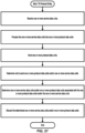
- the method includes receiving - by a packet data convergence protocol (PDCP) layer of a first transmitting device from a radio resource control (RRC) layer - a configuration information of whether to send an indication of service data unit (SDU) discard; and determining - by the PDCP layer of the first transmitting device - a transmission failure of at least one PDCP service data unit (SDU), wherein a plurality of PDCP SDUs, comprising a data unit of a data flow, comprise the at least one PDCP SDU; discarding, by the PDCP layer of the first transmitting device and based on the determining, the plurality of PDCP SDUs; and sending - by the PDCP layer of the first transmitting device and based on the configuration information - a PDCP control protocol data unit (PDU) indicating that the plurality of PDCP SDUs
- PDU PDCP control protocol data unit
- Embodiments may be configured to operate as needed.
- the disclosed mechanism may be performed when certain criteria are met, for example, in a wireless device, a base station, a radio environment, a network, a combination of the above, and/or the like.
- Example criteria may be based, at least in part, on for example, wireless device or network node configurations, traffic load, initial system set up, packet sizes, traffic characteristics, a combination of the above, and/or the like.
- various example embodiments may be applied. Therefore, it may be possible to implement example embodiments that selectively implement disclosed protocols.
- a base station may communicate with a mix of wireless devices.
- Wireless devices and/or base stations may support multiple technologies, and/or multiple releases of the same technology.
- Wireless devices may have one or more specific capabilities.
- this disclosure may refer to a base station communicating with a plurality of wireless devices, this disclosure may refer to a subset of the total wireless devices in a coverage area.
- This disclosure may refer to, for example, a plurality of wireless devices of a given LTE or 5G release with a given capability and in a given sector of the base station.
- the plurality of wireless devices in this disclosure may refer to a selected plurality of wireless devices, and/or a subset of total wireless devices in a coverage area which perform according to disclosed methods, and/or the like.
- There may be a plurality of base stations or a plurality of wireless devices in a coverage area that may not comply with the disclosed methods, for example, those wireless devices or base stations may perform based on older releases of LTE or 5G technology.
- phrases “based on”, “in response to”, “depending on”, “employing”, “using”, and similar phrases indicate the presence and/or influence of a particular factor and/or condition on an event and/or action, but do not exclude unenumerated factors and/or conditions from also being present and/or influencing the event and/or action. For example, if action X is performed “based on” condition Y, this is to be interpreted as the action being performed “based at least on” condition Y. For example, if the performance of action X is performed when conditions Y and Z are both satisfied, then the performing of action X may be described as being "based on Y".
- Evolved Node B 4G, Long Term Evolution (LTE), and/or Evolved Universal Terrestrial Radio Access (E-UTRA) standards may use the term Evolved Node B (eNB).
- 5G and/or New Radio (NR) standards may describe AN 102 as a next-generation radio access network (NG-RAN) and may refer to base stations as Next Generation eNB (ng-eNB) and/or Generation Node B (gNB).
- Future standards for example, 6G, 7G, 8G may use new terminology to refer to the elements which implement the methods described in the present disclosure (e.g., wireless devices, base stations, ANs, CNs, and/or components thereof).
- the one or more DNs 158 may comprise public DNs (e.g., the Internet), private DNs, and/or intra-operator DNs. Relative to corresponding components illustrated in FIG. 1A , these components may represent specific implementations and/or terminology.
- Each of the Uu, Xn, and NG interfaces may be associated with a protocol stack.
- the protocol stacks may include a user plane (UP) and a control plane (CP).
- user plane data may include data pertaining to users of the UEs 151, for example, internet content downloaded via a web browser application, sensor data uploaded via a tracking application, or email data communicated to or from an email server.
- Control plane data may comprise signaling and messages that facilitate packaging and routing of user plane data so that it can be exchanged with the DN(s).
- the NG interface for example, may be divided into an NG user plane interface (NG-U) and an NG control plane interface (NG-C).
- the NG-U interface may provide delivery of user plane data between the base stations and the one or more user plane network functions 155B.
- the NG-C interface may be used for control signaling between the base stations and the one or more control plane network functions 155A.
- the NG-C interface may provide, for example, NG interface management, UE context management, UE mobility management, transport of NAS messages, paging, PDU session management, and configuration transfer and/or warning message transmission.
- the NG-C interface may support transmission of user data (for example, a small data transmission for an loT device).
- One or more of the base stations of the NG-RAN 152 may be split into a central unit (CU) and one or more distributed units (DUs).
- a CU may be coupled to one or more DUs via an F1 interface.
- the CU may handle one or more upper layers in the protocol stack and the DU may handle one or more lower layers in the protocol stack.
- the CU may handle RRC, PDCP, and SDAP, and the DU may handle RLC, MAC, and PHY.
- the one or more DUs may be in geographically diverse locations relative to the CU and/or each other. Accordingly, the CU/DU split architecture may permit increased coverage and/or better coordination.
- the gNBs 152A and ng-eNBs 152B may provide different user plane and control plane protocol termination towards the UEs 151.
- the gNB 154A may provide new radio (NR) protocol terminations over a Uu interface associated with a first protocol stack.
- the ng-eNBs 152B may provide Evolved UMTS Terrestrial Radio Access (E-UTRA) protocol terminations over a Uu interface associated with a second protocol stack.
- E-UTRA Evolved UMTS Terrestrial Radio Access
- the 5G-CN 155 may authenticate UEs 151, set up end-to-end connections between UEs 151 and the one or more DNs 158, and provide charging functionality.
- the 5G-CN 155 may be based on a service-based architecture, in which the NFs making up the 5G-CN 155 offer services to each other and to other elements of the communication network 150 via interfaces.
- the 5G-CN 155 may include any number of other NFs and any number of instances of each NF.
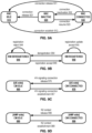
- FIG. 2A, FIG. 2B, FIG. 2C, and FIG. 2D illustrate various examples of a framework for a service-based architecture within a core network.
- a service may be sought by a service consumer and provided by a service producer.
- an NF may determine where such as service can be obtained.
- the NF may communicate with a network repository function (NRF).
- NRF network repository function
- an NF that provides one or more services may register with a network repository function (NRF).
- the NRF may store data relating to the one or more services that the NF is prepared to provide to other NFs in the service-based architecture.
- a consumer NF may query the NRF to discover a producer NF (for example, by obtaining from the NRF a list of NF instances that provide a particular service).
- an NF 211 may send a request 221 to an NF 212 (a producer NF).
- the request 221 may be a request for a particular service and may be sent based on a discovery that NF 212 is a producer of that service.
- the request 221 may comprise data relating to NF 211 and/or the requested service.
- the NF 212 may receive request 221, perform one or more actions associated with the requested service (e.g., retrieving data), and provide a response 221.
- the one or more actions performed by the NF 212 may be based on request data included in the request 221, data stored by NF 212, and/or data retrieved by NF 212.
- the response 222 may notify NF 211 that the one or more actions have been completed.
- the response 222 may comprise response data relating to NF 212, the one or more actions, and/or the requested service.
- an NF 231 sends a request 241 to an NF 232.
- part of the service produced by NF 232 is to send a request 242 to an NF 233.
- the NF 233 may perform one or more actions and provide a response 243 to NF 232.
- NF 232 may send a response 244 to NF 231.
- a single NF may perform the role of producer of services, consumer of services, or both.
- a particular NF service may include any number of nested NF services produced by one or more other NFs.
- the sending of the notifications 263, 264 may be based on a determination that a condition has occurred.
- the notifications 263, 264 may be based on a determination that a particular event has occurred, a determination that a particular condition is outstanding, and/or a determination that a duration of time associated with the subscription has elapsed (for example, a period associated with a subscription for periodic notifications).
- NF 252 may send notifications 263, 264 to NFs 251, 253 simultaneously and/or in response to the same condition.
- the NF 252 may provide notifications at different times and/or in response to different notification conditions.
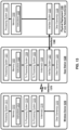
- the NFs depicted in FIG. 3 include a user plane function (UPF) 305, an access and mobility management function (AMF) 312, a session management function (SMF) 314, a policy control function (PCF) 320, a network repository function (NRF) 330, a network exposure function (NEF) 340, a unified data management (UDM) 350, an authentication server function (AUSF) 360, a network slice selection function (NSSF) 370, a charging function (CHF) 380, a network data analytics function (NWDAF) 390, and an application function (AF) 399.
- UPF user plane function
- AMF access and mobility management function
- SMF session management function
- PCF policy control function
- NRF network repository function
- NEF network exposure function
- UDM unified data management
- AUSF authentication server function
- NSSF network slice selection function
- CHF charging function
- NWDAF network data analytics function
- AF application function
- the AMF 312 depicted in FIG. 3 may control UE access to the core network.
- the UE 301 may register with the network via AMF 312. It may be necessary for UE 301 to register prior to establishing a PDU session.
- the AMF 312 may manage a registration area of UE 301, enabling the network to track the physical location of UE 301 within the network.
- AMF 312 may manage UE mobility, for example, handovers from one AN or portion thereof to another.
- AMF 312 may perform registration updates and/or page the UE to transition the UE to connected mode.
- the AMF 312 may receive, from UE 301, non-access stratum (NAS) messages transmitted in accordance with NAS protocol.
- NAS messages relate to communications between UE 301 and the core network. Although NAS messages may be relayed to AMF 312 via AN 302, they may be described as communications via the N1 interface.
- NAS messages may facilitate UE registration and mobility management, for example, by authenticating, identifying, configuring, and/or managing a connection of UE 301.
- NAS messages may support session management procedures for maintaining user plane connectivity and quality of service (QoS) of a session between UE 301 and DN 309. If the NAS message involves session management, AMF 312 may send the NAS message to SMF 314.
- QoS quality of service
- the SMF 314 depicted in FIG. 3 may establish, modify, and/or release a PDU session based on messaging received UE 301.
- the SMF 314 may allocate, manage, and/or assign an IP address to UE 301, for example, upon establishment of a PDU session.
- a UE with multiple PDU sessions may be associated with a different SMF for each PDU session.
- SMF 314 may select one or more UPFs to handle a PDU session and may control the handling of the PDU session by the selected UPF by providing rules for packet handling (PDR, FAR, QER, etc.). Rules relating to QoS and/or charging for a particular PDU session may be obtained from PCF 320 and provided to UPF 305.
- the NEF 340 depicted in FIG. 3 may provide an interface to external domains, permitting external domains to selectively access the control plane of the communication network 300.
- the external domain may comprise, for example, third-party network functions, application functions, etc.
- the NEF 340 may act as a proxy between external elements and network functions such as AMF 312, SMF 314, PCF 320, UDM 350, etc.
- NEF 340 may determine a location or reachability status of UE 301 based on reports from AMF 312, and provide status information to an external element.
- an external element may provide, via NEF 340, information that facilitates the setting of parameters for establishment of a PDU session.
- the NEF 340 may determine which data and capabilities of the control plane are exposed to the external domain.
- the NEF 340 may provide secure exposure that authenticates and/or authorizes an external entity to which data or capabilities of the communication network 300 are exposed.
- the NEF 340 may selectively control the exposure such that the internal architecture of the core network is hidden from the
- the UDM 350 may provide data storage for other NFs.
- the UDM 350 may permit a consolidated view of network information that may be used to ensure that the most relevant information can be made available to different NFs from a single resource.
- the UDM 350 may store and/or retrieve information from a unified data repository (UDR). For example, UDM 350 may obtain user subscription data relating to UE 301 from the UDR.
- UDR unified data repository
- the AUSF 360 may support mutual authentication of UE 301 by the core network and authentication of the core network by UE 301.
- the AUSF 360 may perform key agreement procedures and provide keying material that can be used to improve security.
- the NSSF 370 may select one or more network slices to be used by the UE 301.
- the NSSF 370 may select a slice based on slice selection information.
- the NSSF 370 may receive Single Network Slice Selection Assistance Information (S-NSSAI) and map the S-NSSAI to a network slice instance identifier (NSI).
- S-NSSAI Single Network Slice Selection Assistance Information
- NSI network slice instance identifier
- the CHF 380 may control billing-related tasks associated with UE 301.
- UPF 305 may report traffic usage associated with UE 301 to SMF 314.
- the SMF 314 may collect usage data from UPF 305 and one or more other UPFs. The usage data may indicate how much data is exchanged, what DN the data is exchanged with, a network slice associated with the data, or any other information that may influence billing.
- the SMF 314 may share the collected usage data with the CHF.
- the CHF may use the collected usage data to perform billing-related tasks associated with UE 301.
- the CHF may, depending on the billing status of UE 301, instruct SMF 314 to limit or influence access of UE 301 and/or to provide billing-related notifications to UE 301.
- the NWDAF 390 may collect and analyze data from other network functions and offer data analysis services to other network functions. As an example, NWDAF 390 may collect data relating to a load level for a particular network slice instance from UPF 305, AMF 312, and/or SMF 314. Based on the collected data, NWDAF 390 may provide load level data to the PCF 320 and/or NSSF 370, and/or notify the PC220 and/or NSSF 370 if load level for a slice reaches and/or exceeds a load level threshold.
- the AF 399 may be outside the core network, but may interact with the core network to provide information relating to the QoS requirements or traffic routing preferences associated with a particular application.
- the AF 399 may access the core network based on the exposure constraints imposed by the NEF 340. However, an operator of the core network may consider the AF 399 to be a trusted domain that can access the network directly.
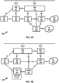
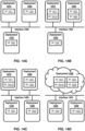
- FIGS. 4A, 4B , and 5 illustrate other examples of core network architectures that are analogous in some respects to the core network architecture 300 depicted in FIG. 3 .
- some of the core network elements depicted in FIG. 3 are omitted.
- Many of the elements depicted in FIGS. 4A, 4B , and 5 are analogous in some respects to elements depicted in FIG. 3 .
- some of the details relating to their functions or operation are omitted.
- FIG. 4A illustrates an example of a core network architecture 400A comprising an arrangement of multiple UPFs.
- Core network architecture 400A includes a UE 401, an AN 402, an AMF 412, and an SMF 414.
- FIG. 4A depicts multiple UPFs, including a UPF 405, a UPF 406, and a UPF 407, and multiple DNs, including a DN 408 and a DN 409.
- Each of the multiple UPFs 405, 406, 407 may communicate with the SMF 414 via an N4 interface.
- the DNs 408, 409 communicate with the UPFs 405, 406, respectively, via N6 interfaces.
- the multiple UPFs 405, 406, 407 may communicate with one another via N9 interfaces.
- the UPFs 405, 406, 407 may perform traffic detection, in which the UPFs identify and/or classify packets. Packet identification may be performed based on packet detection rules (PDR) provided by the SMF 414.
- PDR packet detection rules
- a PDR may include packet detection information comprising one or more of: a source interface, a UE IP address, core network (CN) tunnel information (e.g., a CN address of an N3/N9 tunnel corresponding to a PDU session), a network instance identifier, a quality of service flow identifier (QFI), a filter set (for example, an IP packet filter set or an ethernet packet filter set), and/or an application identifier.
- CN core network
- QFI quality of service flow identifier
- filter set for example, an IP packet filter set or an ethernet packet filter set
- an application identifier for example, an IP packet filter set or an ethernet packet filter set
- a PDR may further indicate rules for handling the packet upon detection thereof.
- the rules may include, for example, forwarding action rules (FARs), multi-access rules (MARs), usage reporting rules (URRs), QoS enforcement rules (QERs), etc.
- FARs forwarding action rules
- MARs multi-access rules
- URRs usage reporting rules
- QERs QoS enforcement rules
- the PDR may comprise one or more FAR identifiers, MAR identifiers, URR identifiers, and/or QER identifiers. These identifiers may indicate the rules that are prescribed for the handling of a particular detected packet.
- the UPF 405 may perform traffic forwarding in accordance with a FAR.
- the FAR may indicate that a packet associated with a particular PDR is to be forwarded, duplicated, dropped, and/or buffered.
- the FAR may indicate a destination interface, for example, "access" for downlink or "core" for uplink.
- the FAR may indicate a buffering action rule (BAR).
- BAR buffering action rule
- UPF 405 may perform data buffering of a certain number downlink packets if a PDU session is deactivated.
- the UPF 405 may perform QoS enforcement in accordance with a QER.
- the QER may indicate a guaranteed bitrate that is authorized and/or a maximum bitrate to be enforced for a packet associated with a particular PDR.
- the QER may indicate that a particular guaranteed and/or maximum bitrate may be for uplink packets and/or downlink packets.
- the UPF 405 may mark packets belonging to a particular QoS flow with a corresponding QFI. The marking may enable a recipient of the packet to determine a QoS of the packet.
- the UPF 405 may provide usage reports to the SMF 414 in accordance with a URR.
- the URR may indicate one or more triggering conditions for generation and reporting of the usage report, for example, immediate reporting, periodic reporting, a threshold for incoming uplink traffic, or any other suitable triggering condition.
- the URR may indicate a method for measuring usage of network resources, for example, data volume, duration, and/or event.
- the DNs 408, 409 may comprise public DNs (e.g., the Internet), private DNs (e.g., private, internal corporate-owned DNs), and/or intra-operator DNs.
- Each DN may provide an operator service and/or a third-party service.
- the service provided by a DN may be the Internet, an IP multimedia subsystem (IMS), an augmented or virtual reality network, an edge computing or mobile edge computing (MEC) network, etc.
- Each DN may be identified using a data network name (DNN).
- the UE 401 may be configured to establish a first logical connection with DN 408 (a first PDU session), a second logical connection with DN 409 (a second PDU session), or both simultaneously (first and second PDU sessions).
- Each PDU session may be associated with at least one UPF configured to operate as a PDU session anchor (PSA, or "anchor").
- PSA PDU session anchor
- the anchor may be a UPF that provides an N6 interface with a DN.
- UPF 405 may be the anchor for the first PDU session between UE 401 and DN 408, whereas the UPF 406 may be the anchor for the second PDU session between UE 401 and DN 409.
- the core network may use the anchor to provide service continuity of a particular PDU session (for example, IP address continuity) as UE 401 moves from one access network to another.
- a particular PDU session for example, IP address continuity
- the data path may include UPF 405 acting as anchor.
- the UE 401 later moves into the coverage area of the AN 402.
- the SMF 414 may allocate, manage, and/or assign an IP address to UE 401, for example, upon establishment of a PDU session.
- the SMF 414 may maintain an internal pool of IP addresses to be assigned.
- the SMF 414 may, if necessary, assign an IP address provided by a dynamic host configuration protocol (DHCP) server or an authentication, authorization, and accounting (AAA) server.
- IP address management may be performed in accordance with a session and service continuity (SSC) mode.
- SSC mode 1 an IP address of UE 401 may be maintained (and the same anchor UPF may be used) as the wireless device moves within the network.
- the selected AMF may be, for example, the same AMF that is used by UE 401 for 3GPP access (AMF 412 in the present example).
- the N31WF 404 may communicate with AMF 412 via an N2 interface.
- the UPF 405 may be selected and N31WF 404 may communicate with UPF 405 via an N3 interface.
- the UPF 405 may be a PDU session anchor (PSA) and may remain the anchor for the PDU session even as UE 401 shifts between trusted access and untrusted access.
- PSA PDU session anchor
- FIG. 5 illustrates an example of a core network architecture 500 in which a UE 501 is in a roaming scenario.
- UE 501 is a subscriber of a first PLMN (a home PLMN, or HPLMN) but attaches to a second PLMN (a visited PLMN, or VPLMN).
- Core network architecture 500 includes UE 501, an AN 502, a UPF 505, and a DN 508.
- the AN 502 and UPF 505 may be associated with a VPLMN.
- the VPLMN may manage the AN 502 and UPF 505 using core network elements associated with the VPLMN, including an AMF 512, an SMF 514, a PCF 520, an NRF 530, an NEF 540, and an NSSF 570.
- An AF 599 may be adjacent the core network of the VPLMN.
- the UE 501 may not be a subscriber of the VPLMN.
- the AMF 512 may authorize UE 501 to access the network based on, for example, roaming restrictions that apply to UE 501.
- it may be necessary for the core network of the VPLMN to interact with core network elements of a HPLMN of UE 501, in particular, a PCF 521, an NRF 531, an NEF 541, a UDM 551, and/or an AUSF 561.
- the VPLMN and HPLMN may communicate using an N32 interface connecting respective security edge protection proxies (SEPPs).
- SEPPs security edge protection proxies
- FIG. 5 the respective SEPPs are depicted as a VSEPP 590 and an HSEPP 591.
- the VPLMN may authenticate UE 501 and/or obtain subscription data of UE 501 by accessing, via the SEPPs, the UDM 551 and AUSF 561 of the HPLMN.
- the core network architecture 500 depicted in FIG. 5 may be referred to as a local breakout configuration, in which UE 501 accesses DN 508 using one or more UPFs of the VPLMN (i.e., UPF 505).
- UPF 505 UPFs of the VPLMN
- other configurations are possible.
- UE 501 may access a DN using one or more UPFs of the HPLMN.
- an N9 interface may run parallel to the N32 interface, crossing the frontier between the VPLMN and the HPLMN to carry user plane data.
- One or more SMFs of the respective PLMNs may communicate via the N32 interface to coordinate session management for UE 501.
- the SMFs may control their respective UPFs on either side of the frontier.
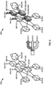
- FIG. 6 illustrates an example of network slicing.
- Network slicing may refer to division of shared infrastructure (e.g., physical infrastructure) into distinct logical networks. These distinct logical networks may be independently controlled, isolated from one another, and/or associated with dedicated resources.
- Network architecture 600B is an example of a sliced physical network divided into multiple logical networks.
- the physical network is divided into three logical networks, referred to as slice A, slice B, and slice C.
- UE 601A may be served by AN 602A, UPF 605A, AMF 612, and SMF 614A.
- UE 601B may be served by AN 602B, UPF 605B, AMF 612, and SMF 614B.
- UE 601C may be served by AN 602C, UPF 605C, AMF 612, and SMF 614C.
- the respective UEs 601 communicate with different network elements from a logical perspective, these network elements may be deployed by a network operator using the same physical network elements.
- slice A may correspond to enhanced mobile broadband (eMBB) service.
- Mobile broadband may refer to internet access by mobile users, commonly associated with smartphones.
- Slice B may correspond to ultra-reliable low-latency communication (URLLC), which focuses on reliability and speed. Relative to eMBB, URLLC may improve the feasibility of use cases such as autonomous driving and telesurgery.
- URLLC ultra-reliable low-latency communication
- Slice C may correspond to massive machine type communication (mMTC), which focuses on low-power services delivered to a large number of users.
- slice C may be optimized for a dense network of battery-powered sensors that provide small amounts of data at regular intervals. Many mMTC use cases would be prohibitively expensive if they operated using an eMBB or URLLC network.
- each of the UEs 601 has its own network slice.
- a single slice may serve any number of UEs and a single UE may operate using any number of slices.
- the AN 602, UPF 605 and SMF 614 are separated into three separate slices, whereas the AMF 612 is unsliced.
- a network operator may deploy any architecture that selectively utilizes any mix of sliced and unsliced network elements, with different network elements divided into different numbers of slices.
- FIG. 6 only depicts three core network functions, it will be understood that other core network functions may be sliced as well.
- a PLMN that supports multiple network slices may maintain a separate network repository function (NFR) for each slice, enabling other NFs to discover network services associated with that slice.
- NFR network repository function
- Network slice selection may be controlled by an AMF, or alternatively, by a separate network slice selection function (NSSF).
- a network operator may define and implement distinct network slice instances (NSIs).
- Each NSI may be associated with single network slice selection assistance information (S-NSSAI).
- the S-NSSAI may include a particular slice/service type (SST) indicator (indicating eMBB, URLLC, mMTC, etc.).
- SST slice/service type
- a particular tracking area may be associated with one or more configured S-NSSAls.
- UEs may identify one or more requested and/or subscribed S-NSSAIs (e.g., during registration).
- the network may indicate to the UE one or more allowed and/or rejected S-NSSAls.
- the S-NSSAI may further include a slice differentiator (SD) to distinguish between different tenants of a particular slice and/or service type.
- SD slice differentiator
- a tenant may be a customer (e.g., vehicle manufacture, service provider, etc.) of a network operator that obtains (for example, purchases) guaranteed network resources and/or specific policies for handling its subscribers.
- the network operator may configure different slices and/or slice types, and use the SD to determine which tenant is associated with a particular slice.
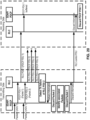
- FIG. 7A, FIG. 7B, and FIG. 7C illustrate a user plane (UP) protocol stack, a control plane (CP) protocol stack, and services provided between protocol layers of the UP protocol stack.
- UP user plane
- CP control plane
- the layers may be associated with an open system interconnection (OSI) model of computer networking functionality.
- OSI open system interconnection
- layer 1 may correspond to the bottom layer, with higher layers on top of the bottom layer.
- Layer 1 may correspond to a physical layer, which is concerned with the physical infrastructure used for transfer of signals (for example, cables, fiber optics, and/or radio frequency transceivers).
- layer 1 may comprise a physical layer (PHY).
- PHY physical layer
- Layer 2 may correspond to a data link layer. Layer 2 may be concerned with packaging of data (into, e.g., data frames) for transfer, between nodes of the network, using the physical infrastructure of layer 1.
- layer 2 may comprise a media access control layer (MAC), a radio link control layer (RLC), a packet data convergence layer (PDCP), and a service data application protocol layer (SDAP).
- MAC media access control layer
- RLC radio link control layer
- PDCP packet data convergence layer
- SDAP service data application protocol layer
- Layer 3 may correspond to a network layer. Layer 3 may be concerned with routing of the data which has been packaged in layer 2. Layer 3 may handle prioritization of data and traffic avoidance. In NR, layer 3 may comprise a radio resource control layer (RRC) and a non-access stratum layer (NAS). Layers 4 through 7 may correspond to a transport layer, a session layer, a presentation layer, and an application layer.
- the application layer interacts with an end user to provide data associated with an application. In an example, an end user implementing the application may generate data associated with the application and initiate sending of that information to a targeted data network (e.g., the Internet, an application server, etc.).
- a targeted data network e.g., the Internet, an application server, etc.
- each layer in the OSI model may manipulate and/or repackage the information and deliver it to a lower layer.
- the manipulated and/or repackaged information may be exchanged via physical infrastructure (for example, electrically, optically, and/or electromagnetically).
- the information will be unpackaged and provided to higher and higher layers, until it once again reaches the application layer in a form that is usable by the targeted data network (e.g., the same form in which it was provided by the end user).
- the data network may perform this procedure in reverse.
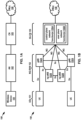
- FIG. 7A illustrates a user plane protocol stack.
- the user plane protocol stack may be a new radio (NR) protocol stack for a Uu interface between a UE 701 and a gNB 702.
- NR new radio
- the UE 701 may implement PHY 731 and the gNB 702 may implement PHY 732.
- the UE 701 may implement MAC 741, RLC 751, PDCP 761, and SDAP 771.
- the gNB 702 may implement MAC 742, RLC 752, PDCP 762, and SDAP 772.
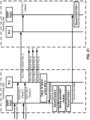
- FIG. 7B illustrates a control plane protocol stack.
- the control plane protocol stack may be an NR protocol stack for the Uu interface between the UE 701 and the gNB 702 and/or an N1 interface between the UE 701 and an AMF 712.
- the UE 701 may implement PHY 731 and the gNB 702 may implement PHY 732.
- the UE 701 may implement MAC 741, RLC 751, PDCP 761, RRC 781, and NAS 791.
- the gNB 702 may implement MAC 742, RLC 752, PDCP 762, and RRC 782.
- the AMF 712 may implement NAS 792.
- the NAS may be concerned with the non-access stratum, in particular, communication between the UE 701 and the core network (e.g., the AMF 712). Lower layers may be concerned with the access stratum, for example, communication between the UE 701 and the gNB 702. Messages sent between the UE 701 and the core network may be referred to as NAS messages.
- a NAS message may be relayed by the gNB 702, but the content of the NAS message (e.g., information elements of the NAS message) may not be visible to the gNB 702.
- FIG. 7C illustrates an example of services provided between protocol layers of the NR user plane protocol stack illustrated in FIG. 7A .
- the UE 701 may receive services through a PDU session, which may be a logical connection between the UE 701 and a data network (DN).
- the UE 701 and the DN may exchange data packets associated with the PDU session.
- the PDU session may comprise one or more quality of service (QoS) flows.
- SDAP 771 and SDAP 772 may perform mapping and/or demapping between the one or more QoS flows of the PDU session and one or more radio bearers (e.g., data radio bearers).
- QoS quality of service
- the mapping between the QoS flows and the data radio bearers may be determined in the SDAP 772 by the gNB 702, and the UE 701 may be notified of the mapping (e.g., based on control signaling and/or reflective mapping).
- the SDAP 772 of the gNB 220 may mark downlink packets with a QoS flow indicator (QFI) and deliver the downlink packets to the UE 701.
- QFI QoS flow indicator
- the UE 701 may determine the mapping based on the QFI of the downlink packets.
- PDCP 761 and PDCP 762 may perform header compression and/or decompression. Header compression may reduce the amount of data transmitted over the physical layer.
- the PDCP 761 and PDCP 762 may perform ciphering and/or deciphering. Ciphering may reduce unauthorized decoding of data transmitted over the physical layer (e.g., intercepted on an air interface), and protect data integrity (e.g., to ensure control messages originate from intended sources).
- the PDCP 761 and PDCP 762 may perform retransmissions of undelivered packets, in-sequence delivery and reordering of packets, duplication of packets, and/or identification and removal of duplicate packets. In a dual connectivity scenario, PDCP 761 and PDCP 762 may perform mapping between a split radio bearer and RLC channels.
- RLC 751 and RLC 752 may perform segmentation, retransmission through Automatic Repeat Request (ARQ).
- the RLC 751 and RLC 752 may perform removal of duplicate data units received from MAC 741 and MAC 742, respectively.
- the RLCs 213 and 223 may provide RLC channels as a service to PDCPs 214 and 224, respectively.
- MAC 741 and MAC 742 may perform multiplexing and/or demultiplexing of logical channels.
- MAC 741 and MAC 742 may map logical channels to transport channels.
- UE 701 may, in MAC 741, multiplex data units of one or more logical channels into a transport block.
- the UE 701 may transmit the transport block to the gNB 702 using PHY 731.
- the gNB 702 may receive the transport block using PHY 732 and demultiplex data units of the transport blocks back into logical channels.
- MAC 741 and MAC 742 may perform error correction through Hybrid Automatic Repeat Request (HARQ), logical channel prioritization, and/or padding.
- HARQ Hybrid Automatic Repeat Request
- FIG. 8 illustrates an example of a quality of service (QoS) model for differentiated data exchange.
- QoS quality of service
- the QoS model facilitates prioritization of certain packet or protocol data units (PDUs), also referred to as packets. For example, higher-priority packets may be exchanged faster and/or more reliably than lower-priority packets.
- PDUs protocol data units
- the network may devote more resources to exchange of high-QoS packets.
- a PDU session 810 is established between UE 801 and UPF 805.
- the PDU session 810 may be a logical connection enabling the UE 801 to exchange data with a particular data network (for example, the Internet).
- the UE 801 may request establishment of the PDU session 810.
- the UE 801 may, for example, identify the targeted data network based on its data network name (DNN).
- the PDU session 810 may be managed, for example, by a session management function (SMF, not shown).
- SMF session management function
- the SMF may select the UPF 805 (and optionally, one or more other UPFs, not shown).
- One or more applications associated with UE 801 may generate uplink packets 812A-812E associated with the PDU session 810.
- UE 801 may apply QoS rules 814 to uplink packets 812A-812E.
- the QoS rules 814 may be associated with PDU session 810 and may be determined and/or provided to the UE 801 when PDU session 810 is established and/or modified.
- UE 801 may classify uplink packets 812A-812E, map each of the uplink packets 812A-812E to a QoS flow, and/or mark uplink packets 812A-812E with a QoS flow indicator (QFI).
- QFI QoS flow indicator
- the QFI indicates how the packet should be handled in accordance with the QoS model.
- uplink packets 812A, 812B are mapped to QoS flow 816A
- uplink packet 812C is mapped to QoS flow 816B
- the remaining packets are mapped to QoS flow 816C.
- the QoS flows may be the finest granularity of QoS differentiation in a PDU session.
- three QoS flows 816A-816C are illustrated. However, it will be understood that there may be any number of QoS flows.
- Some QoS flows may be associated with a guaranteed bit rate (GBR QoS flows) and others may have bit rates that are not guaranteed (non-GBR QoS flows).
- QoS flows may also be subject to per-UE and per-session aggregate bit rates.
- One of the QoS flows may be a default QoS flow.
- the QoS flows may have different priorities. For example, QoS flow 816A may have a higher priority than QoS flow 816B, which may have a higher priority than QoS flow 816C.
- QoS flows may be associated with flow bit rates.
- a particular QoS flow may be associated with a guaranteed flow bit rate (GFBR) and/or a maximum flow bit rate (MFBR).
- QoS flows may be associated with specific packet delay budgets (PDBs), packet error rates (PERs), and/or maximum packet loss rates.
- PDBs packet delay budgets
- PERs packet error rates
- QoS flows may also be subject to per-UE and per-session aggregate bit rates.
- UE 801 may apply resource mapping rules 818 to the QoS flows 816A-816C.
- the air interface between UE 801 and AN 802 may be associated with resources 820.
- QoS flow 816A is mapped to resource 820A
- QoS flows 816B, 816C are mapped to resource 820B.
- the resource mapping rules 818 may be provided by the AN 802. In order to meet QoS requirements, the resource mapping rules 818 may designate more resources for relatively high-priority QoS flows.
- a high-priority QoS flow such as QoS flow 816A may be more likely to obtain the high flow bit rate, low packet delay budget, or other characteristic associated with QoS rules 814.
- the resources 820 may comprise, for example, radio bearers.
- the radio bearers (e.g., data radio bearers) may be established between the UE 801 and the AN 802.
- the radio bearers in 5G, between the UE 801 and the AN 802 may be distinct from bearers in LTE, for example, Evolved Packet System (EPS) bearers between a UE and a packet data network gateway (PGW), S1 bearers between an eNB and a serving gateway (SGW), and/or an S5/S8 bearer between an SGW and a PGW.
- EPS Evolved Packet System
- PGW packet data network gateway
- SGW serving gateway
- S5/S8 bearer between an SGW and a PGW.
- AN 802 may separate packets into respective QoS flows 856A-856C based on QoS profiles 828.
- the QoS profiles 828 may be received from an SMF.
- Each QoS profile may correspond to a QFI, for example, the QFI marked on the uplink packets 812A-812E.
- Each QoS profile may include QoS parameters such as 5G QoS identifier (5QI) and an allocation and retention priority (ARP).
- 5QI 5G QoS identifier
- ARP allocation and retention priority
- the QoS profile for non-GBR QoS flows may further include additional QoS parameters such as a reflective QoS attribute (RQA).
- the QoS profile for GBR QoS flows may further include additional QoS parameters such as a guaranteed flow bit rate (GFBR), a maximum flow bit rate (MFBR), and/or a maximum packet loss rate.
- GFBR guaranteed flow bit rate
- MFBR maximum flow bit rate
- the 5QI may be a standardized 5QI which have one-to-one mapping to a standardized combination of 5G QoS characteristics per well-known services.
- the 5QI may be a dynamically assigned 5QI which the standardized 5QI values are not defined.
- the 5QI may represent 5G QoS characteristics.
- the 5QI may comprise a resource type, a default priority level, a packet delay budget (PDB), a packet error rate (PER), a maximum data burst volume, and/or an averaging window.
- the resource type may indicate a non-GBR QoS flow, a GBR QoS flow or a delay-critical GBR QoS flow.
- the averaging window may represent a duration over which the GFBR and/or MFBR is calculated.
- ARP may be a priority level comprising pre-emption capability and a pre-emption vulnerability. Based on the ARP, the AN 802 may apply admission control for the QoS flows in a case of resource limitations.
- the AN 802 may select one or more N3 tunnels 850 for transmission of the QoS flows 856A-856C. After the packets are divided into QoS flows 856A-856C, the packet may be sent to UPF 805 (e.g., towards a DN) via the selected one or more N3 tunnels 850.
- the UPF 805 may verify that the QFIs of the uplink packets 812A-812E are aligned with the QoS rules 814 provided to the UE 801.
- the UPF 805 may measure and/or count packets and/or provide packet metrics to, for example, a PCF.
- the figure also illustrates a process for downlink.
- one or more applications may generate downlink packets 852A-852E.
- the UPF 805 may receive downlink packets 852A-852E from one or more DNs and/or one or more other UPFs.
- UPF 805 may apply packet detection rules (PDRs) 854 to downlink packets 852A-852E.
- PDRs packet detection rules
- UPF 805 may map packets 852A-852E into QoS flows.
- downlink packets 852A, 852B are mapped to QoS flow 856A
- downlink packet 852C is mapped to QoS flow 856B
- the remaining packets are mapped to QoS flow 856C.
- the QoS flows 856A-856C may be sent to AN 802.
- the AN 802 may apply resource mapping rules to the QoS flows 856A-856C.
- QoS flow 856A is mapped to resource 820A
- QoS flows 856B, 856C are mapped to resource 820B.
- the resource mapping rules may designate more resources to high-priority QoS flows.
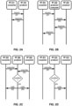
- FIGS. 9A- 9D illustrate example states and state transitions of a wireless device (e.g., a UE).
- the wireless device may have a radio resource control (RRC) state, a registration management (RM) state, and a connection management (CM) state.
- RRC radio resource control
- RM registration management
- CM connection management
- FIG. 9A is an example diagram showing RRC state transitions of a wireless device (e.g., a UE).
- the UE may be in one of three RRC states: RRC idle 910, (e.g., RRC _IDLE), RRC inactive 920 (e.g., RRC _INACTIVE), or RRC connected 930 (e.g., RRC _CONNECTED).
- RRC idle 910 e.g., RRC _IDLE
- RRC inactive 920 e.g., RRC _INACTIVE
- RRC connected 930 e.g., RRC _CONNECTED
- the UE may implement different RAN-related control-plane procedures depending on its RRC state.
- Other elements of the network for example, a base station, may track the RRC state of one or more UEs and implement RAN-related control-plane procedures appropriate to the RRC state of each.
- the RRC state may transition from RRC connected 930 to RRC idle 910 through a connection release procedure 930 or to RRC inactive 920 through a connection inactivation procedure 932.
- RRC idle 910 an RRC context may not be established for the UE.
- the UE may not have an RRC connection with a base station.
- the UE may be in a sleep state for a majority of the time (e.g., to conserve battery power).
- the UE may wake up periodically (e.g., once in every discontinuous reception cycle) to monitor for paging messages from the access network.
- Mobility of the UE may be managed by the UE through a procedure known as cell reselection.
- the RRC state may transition from RRC idle 910 to RRC connected 930 through a connection establishment procedure 913, which may involve a random access procedure, as discussed in greater detail below.
- RRC inactive 920 the RRC context previously established is maintained in the UE and the base station. This may allow for a fast transition to RRC connected 930 with reduced signaling overhead as compared to the transition from RRC idle 910 to RRC connected 930.
- the RRC state may transition to RRC connected 930 through a connection resume procedure 923.
- the RRC state may transition to RRC idle 910 though a connection release procedure 921 that may be the same as or similar to connection release procedure 931.
- An RRC state may be associated with a mobility management mechanism.
- mobility may be managed by the UE through cell reselection.
- the purpose of mobility management in RRC idle 910 and/or RRC inactive 920 is to allow the network to be able to notify the UE of an event via a paging message without having to broadcast the paging message over the entire mobile communications network.
- the mobility management mechanism used in RRC idle 910 and/or RRC inactive 920 may allow the network to track the UE on a cell-group level so that the paging message may be broadcast over the cells of the cell group that the UE currently resides within instead of the entire communication network. Tracking may be based on different granularities of grouping.
- RAN area identifier RAI
- TAI tracking area identifier
- Tracking areas may be used to track the UE at the CN level.
- the CN may provide the UE with a list of TAls associated with a UE registration area. If the UE moves, through cell reselection, to a cell associated with a TAI not included in the list of TAls associated with the UE registration area, the UE may perform a registration update with the CN to allow the CN to update the UE's location and provide the UE with a new the UE registration area.
- RAN areas may be used to track the UE at the RAN level.
- the UE may be assigned a RAN notification area.
- a RAN notification area may comprise one or more cell identities, a list of RAls, and/or a list of TAls.
- a base station may belong to one or more RAN notification areas.
- a cell may belong to one or more RAN notification areas. If the UE moves, through cell reselection, to a cell not included in the RAN notification area assigned to the UE, the UE may perform a notification area update with the RAN to update the UE's RAN notification area.
- a base station storing an RRC context for a UE or a last serving base station of the UE may be referred to as an anchor base station.
- An anchor base station may maintain an RRC context for the UE at least during a period of time that the UE stays in a RAN notification area of the anchor base station and/or during a period of time that the UE stays in RRC inactive 920.
- FIG. 9B is an example diagram showing registration management (RM) state transitions of a wireless device (e.g., a UE).
- the states are RM deregistered 940, (e.g., RM-DEREGISTERED) and RM registered 950 (e.g., RM-REGISTERED).
- RM deregistered 940 the UE is not registered with the network, and the UE is not reachable by the network. In order to be reachable by the network, the UE must perform an initial registration. As an example, the UE may register with an AMF of the network. If registration is rejected (registration reject 944), then the UE remains in RM deregistered 940. If registration is accepted (registration accept 945), then the UE transitions to RM registered 950. While the UE is RM registered 950, the network may store, keep, and/or maintain a UE context for the UE. The UE context may be referred to as wireless device context.
- the UE context corresponding to network registration may be different from the RRC context corresponding to RRC state (maintained by an access network, .e.g., a base station).
- the UE context may comprise a UE identifier and a record of various information relating to the UE, for example, UE capability information, policy information for access and mobility management of the UE, lists of allowed or established slices or PDU sessions, and/or a registration area of the UE (i.e., a list of tracking areas covering the geographical area where the wireless device is likely to be found).
- the network may store the UE context of the UE, and if necessary use the UE context to reach the UE. Moreover, some services may not be provided by the network unless the UE is registered.
- the UE may update its UE context while remaining in RM registered 950 (registration update accept 955). For example, if the UE leaves one tracking area and enters another tracking area, the UE may provide a tracking area identifier to the network.
- the network may deregister the UE, or the UE may deregister itself (deregistration 954). For example, the network may automatically deregister the wireless device if the wireless device is inactive for a certain amount of time. Upon deregistration, the UE may transition to RM deregistered 940.
- FIG. 9C is an example diagram showing connection management (CM) state transitions of a wireless device (e.g., a UE), shown from a perspective of the wireless device.
- the UE may be in CM idle 960 (e.g., CM-IDLE) or CM connected 970 (e.g., CM-CONNECTED).
- the UE can communicate with core network functions using NAS signaling.
- the UE may exchange NAS signaling with an AMF for registration management purposes, service request procedures, and/or authentication procedures.
- the UE may exchange NAS signaling, with an SMF, to establish and/or modify a PDU session.
- the network may disconnect the UE, or the UE may disconnect itself (AN signaling connection release 976). For example, if the UE transitions to RM deregistered 940, then the UE may also transition to CM idle 960. When the UE transitions to CM idle 960, the network may deactivate a user plane connection of a PDU session of the UE.
- AMF#2 retrieves access and mobility (AM) policies from the PCF.
- the AMF#2 may provide subscription data of the UE to the PCF.
- the PCF may determine access and mobility policies for the UE based on the subscription data, network operator data, current network conditions, and/or other suitable information. For example, the owner of a first UE may purchase a higher level of service than the owner of a second UE.
- the PCF may provide the rules associated with the different levels of service. Based on the subscription data of the respective UEs, the network may apply different policies which facilitate different levels of service.
- the network may authenticate the UE. Authentication may require participation of the UE, an AUSF, and/or a UDM, for example, similar to authentication described elsewhere in the present disclosure. In some cases (for example, if the UE has recently been authenticated), the authentication at 1150 may be skipped.
- the AMF and SMF may perform a PDU session update.
- the SMF may provide the AMF with one or more UPF tunnel endpoint identifiers.
- the UE may receive, at 1170, a NAS service accept message from the AMF via the AN. After the user plane resource is configured, the UE may transmit uplink data (for example, the uplink data that caused the UE to trigger the service request procedure).
- uplink data for example, the uplink data that caused the UE to trigger the service request procedure.
- the SMF may update a PCF for purposes of policy control. For example, if a location of the UE has changed, the SMF may notify the PCF of the UE's a new location.
- the SMF and UPF may perform a session modification.
- the session modification may be performed using N4 session modification messages.
- the UPF may transmit downlink data (for example, the downlink data that caused the UPF to trigger the network-triggered service request procedure) to the UE.
- the transmitting of the downlink data may be based on the one or more AN tunnel endpoint identifiers of the AN.
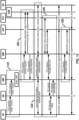
- FIG. 12 illustrates an example of a protocol data unit (PDU) session establishment procedure for a wireless device (e.g., a UE).
- the UE may determine to transmit the PDU session establishment request to create a new PDU session, to hand over an existing PDU session to a 3GPP network, or for any other suitable reason.
- PDU protocol data unit
- the UE initiates PDU session establishment.
- the UE may transmit a PDU session establishment request to an AMF via an AN.
- the PDU session establishment request may be a NAS message.
- the PDU session establishment request may indicate: a PDU session ID; a requested PDU session type (new or existing); a requested DN (DNN); a requested network slice (S-NSSAI); a requested SSC mode; and/or any other suitable information.
- the PDU session ID may be generated by the UE.
- the PDU session type may be, for example, an Internet Protocol (IP)-based type (e.g., IPv4, IPv6, or dual stack IPv4/IPv6), an Ethernet type, or an unstructured type.
- IP Internet Protocol
- the AMF may select an SMF based on the PDU session establishment request.
- the requested PDU session may already be associated with a particular SMF.
- the AMF may store a UE context of the UE, and the UE context may indicate that the PDU session ID of the requested PDU session is already associated with the particular SMF.
- the AMF may select the SMF based on a determination that the SMF is prepared to handle the requested PDU session.
- the requested PDU session may be associated with a particular DNN and/or S-NSSAI, and the SMF may be selected based on a determination that the SMF can manage a PDU session associated with the particular DNN and/or S-NSSAI.
- the SMF may subscribe for updates to the subscription data, so that the PCF will send new information if the subscription data of the UE changes.
- the SMF may transmit a PDU session context response to the AMG.
- the PDU session context response may be a Nsmf_ PDUSession_ CreateSMContext Response and/or a Nsmf_PDUSession_UpdateSMContext Response.
- the PDU session context response may include a session management context ID.
- secondary authorization/authentication may be performed, if necessary.
- the secondary authorization/authentication may involve the UE, the AMF, the SMF, and the DN.
- the SMF may access the DN via a Data Network Authentication, Authorization and Accounting (DN AAA) server.
- DN AAA Data Network Authentication, Authorization and Accounting
- the network sets up a data path for uplink data associated with the PDU session.
- the SMF may select a PCF and establish a session management policy association. Based on the association, the PCF may provide an initial set of policy control and charging rules (PCC rules) for the PDU session.
- PCC rules policy control and charging rules
- the PCF may indicate, to the SMF, a method for allocating an IP address to the PDU Session, a default charging method for the PDU session, an address of the corresponding charging entity, triggers for requesting new policies, etc.
- the PCF may also target a service data flow (SDF) comprising one or more PDU sessions.
- SDF service data flow
- the PCF may indicate, to the SMF, policies for applying QoS requirements, monitoring traffic (e.g., for charging purposes), and/or steering traffic (e.g., by using one or more particular N6 interfaces).
- the SMF may determine and/or allocate an IP address for the PDU session.
- the SMF may select one or more UPFs (a single UPF in the example of FIG. 12 ) to handle the PDU session.
- the SMF may send an N4 session message to the selected UPF.
- the N4 session message may be an N4 Session Establishment Request and/or an N4 Session Modification Request.
- the N4 session message may include packet detection, enforcement, and reporting rules associated with the PDU session.
- the UPF may acknowledge by sending an N4 session establishment response and/or an N4 session modification response.
- the SMF may send PDU session management information to the AMF.
- the PDU session management information may be a session service request (e.g., Namf_Communication_N1 N2MessageTransfer) message.
- the PDU session management information may include the PDU session ID.
- the PDU session management information may be a NAS message.
- the PDU session management information may include N1 session management information and/or N2 session management information.
- the N1 session management information may include a PDU session establishment accept message.
- the PDU session establishment accept message may include tunneling endpoint information of the UPF and quality of service (QoS) information associated with the PDU session.
- QoS quality of service
- the UE may optionally send uplink data associated with the PDU session. As shown in FIG. 12 , the uplink data may be sent to a DN associated with the PDU session via the AN and the UPF.
- the network may update the PDU session context.
- the AMF may transmit a PDU session context update request to the SMF.
- the PDU session context update request may be a Nsmf_PDUSession_UpdateSMContext Request.
- the PDU session context update request may include the N2 session management information received from the AN.
- the SMF may acknowledge the PDU session context update.
- the acknowledgement may be a Nsmf_PDUSession_UpdateSMContext Response.
- the acknowledgement may include a subscription requesting that the SMF be notified of any UE mobility event.
- the SMF may send an N4 session message to the UPF.
- the N4 session message may be an N4 Session Modification Request.
- the N4 session message may include tunneling endpoint information of the AN.
- the N4 session message may include forwarding rules associated with the PDU session.
- the UPF may acknowledge by sending an N4 session modification response.
- the UPF may relay downlink data associated with the PDU session. As shown in FIG. 12 , the downlink data may be received from a DN associated with the PDU session via the AN and the UPF.
- the RLC control PDU may comprise information on the one or more RLC PDUs and/or one or more segments of one or more RLC SDUs and/or one or more RLC SDUs that the transmitting RLC entity aborts transmission.
- the information on the one or more RLC PDUs and/or one or more segments of one or more RLC SDUs and/or the one or more RLC SDUs may comprise one or more sequence numbers associated with the one or more RLC PDUs and/or one or more segments of one or more RLC SDUs and/or the one or more RLC SDUs.
- the receiving RLC entity may update one or more local variables associated with operation of the receiving RLC entity.
- the receiving RLC entity may update one or more local variables associated with one or more sequence numbers (e.g., sequence numbers of next expected RLC SDU and/or sequence numbers of one or more segments of one or more RLC SDUs and/or sequence numbers of acknowledged RLC SDUs and/or sequence numbers associated with a reception/receiving window, etc.)
- the receiving RLC entity may determine one or more RLC PDUs and/or one or more segments of one or more RLC SDUs and/or RLC SDU segments associated with the identified one or more RLC SDUs and/or one or more segments of one or more RLC SDUs and/or one or more RLC SDUs.
- a first transmitting protocol entity may receive one or more packets (e.g., SDUs) from a higher layer (e.g., a SDAP entity, a PDCP entity, an IP entity, and TCP entity and so on).
- the one or more packets may comprise at least one or more packet headers and/or one or more packet payloads.
- the one or more packet payloads may comprise one or more ADUs and/or one or more bytes of one or more ADUs and/or one or more SDUs (e.g., PDCP SDUs, SDAP SDUs, RLC SDUs).
- the third associated ADU information may indicate that an identity of a ADU associated with the third packet is 2.
- the one or more associated ADU information may indicate that the first packet and the second packet are associated.
- the one or more associated ADU information may indicate that the first packet and the third packet are not associated.
- a transmitting PDCP entity may deliver the first PDCP PDU to a transmitting RLC entity.
- the transmitting RLC entity may receive a first RLC SDU (e.g., the first PDCP PDU, PDCP PDU 1, RLC SDU 1).
- the transmitting RLC entity may process the first RLC SDU and may construct one or more RLC PDUs.
- the one or more RLC PDUs may comprise a first RLC PDU (RLC PDU 1).
- the transmitting RLC entity may deliver the one or more RLC PDUs to the MAC entity for transmission.
- One or more RLC PDUs and/or one or more RLC SDUs sent by the transmitting RLC entity may be successfully delivered to a receiving RLC entity.
- One or more RLC PDUs and/or one or more RLC SDU sent by the transmitting RLC entity may not be successfully delivered to the receiving RLC entity.
- the first RLC PDU and/or the first RLC SDU may be successfully delivered to the receiving RLC entity.
- the receiving RLC entity may buffer the successfully received one or more RLC PDUs and/or one or more RLC SDUs in a memory.
- the receiving RLC entity may deliver the one or more successfully received RLC SDUs to a receiving PDCP entity.
- the second RLC PDU and/or the second RLC SDU may not be successfully delivered to the receiving RLC entity.
- the transmitting RLC entity may retransmit the second RLC PDU and/or the second RLC SDU for several times.
- the transmitting RLC entity may determine that the transmission of the RLC PDU 2 and/or the second RLC SDU fails.
- the determination that the transmission of the RLC PDU 2 and/or the second RLC SDU fails may be that the transmitting RLC entity stops transmission of the RLC PDU 2 and/or the RLC SDU 2.
- the determination that the transmission of the RLC PDU 2 and/or the second RLC SDU fails may be that that the transmitting RLC entity aborts the transmission of the RLC PDU 2 and/or the RLC SDU 2.
- the determination that the transmission of the RLC PDU 2 fails may be that that the delivery of the RLC SDU 2 and/or the second RLC SDU fails.
- the transmitting RLC entity may send a delivery information to the transmitting PDCP entity.
- the delivery information may indicate that delivery of a PDCP PDU (e.g., the second PDCP PDU, the second RLC SDU) fails and/or that delivery of a RLC SDU (e.g., the second RLC SDU) fails.
- the delivery information may indicate that an error occurs for the delivery of the PDCP PDU and/or the RLC SDU.
- the transmitting PDCP entity may determine to discard the PDCP PDU indicated by the delivery information. In an example, based on the delivery information, the transmitting PDCP entity may determine to discard a PDCP SDU (e.g., the second PDCP SDU, the second packet) associated with a PDCP PDU indicated by the delivery information. Based on the delivery information from the RLC transmitting entity, the transmitting PDCP entity may determine an ADU information associated with the PDCP PDU.
- a PDCP SDU e.g., the second PDCP SDU, the second packet
- the transmitting PDCP entity may determine that the first packet (e.g., the first PDCP SDU) is associated with the second packet. Based on the determination, the transmitting PDCP entity may discard the first packet (e.g., the first PDCP SDU) and/or the first PDCP PDU. For example, based on that the ADU information associated with the third packet, the transmitting PDCP entity may determine that the third packet (e.g., the third PDCP SDU) is not associated with the second packet. Based on the determination, the transmitting PDCP entity may not discard the third packet (e.g., the third PDCP SDU) and/or the third PDCP PDU.
- the first packet e.g., the first PDCP SDU
- the transmitting PDCP entity may determine that the third packet (e.g., the third PDCP SDU) is associated with the second packet. Based on the determination, the transmitting PDCP entity may not discard the third packet (e.g., the third PDCP
- the transmitting PDCP entity may send a PDCP status report (e.g., PDCP control PDU, PDCP sender report) to a receiving PDCP entity.
- the PDCP status report may comprise information that one or more PDCP SDUs (e.g., the first PDCP SDU, the second PDCP SDU) are discarded and/or are not transmitted.
- the PDCP status report may comprise information that the transmission of the one or more PDCP SDUs (e.g., first PDCP SDU, the second PDCP SDU) are stopped and/or aborted.
- the PDCP status report may comprise information of one or more PDCP SDUs that the transmitting PDCP entity may or may not transmit.
- the PDCP status report may comprise information of the one or more PDCP PDUs associated with one or more ADUs.
- the PDCP status report may comprise information of one or more sequence numbers which the transmitting PDCP entity may transmit.
- the receiving PDCP entity may receive the PDCP control PDU. Based on the received PDCP control PDU, the receiving PDCP entity may identify one or more PDCP PDUs and/or one or more PDCP SDUs that the transmitting PDCP entity does not transmit and/or stops transmission and/or aborts transmission and/or discards. For example, for the identified one or more PDCP PDUs and/or one or more PDCP SDUs, the receiving PDCP entity may behave as if one or more PDCP PDUs and/or one or more PDCP SDUs are received. For example, based on the PDCP control PDU, the receiving PDCP entity may update local variables associated with operation of the receiving PDCP entity.
- the receiving PDCP entity may update local variable associated with a sequence number of next expected PDCP PDU/SDU and/or a sequence number associated with a reception window. For example, for the identified one or more PDCP PDUs and/or one or more PDCP SDUs, the receiving PDCP entity may discard the identified one or more PDCP PDUs and/or one or more PDCP SDUs. For example, for the identified one or more PDCP PDUs and/or one or more PDCP SDUs, the receiving PDCP entity may indicate to a receiving RLC entity, information of the one or more RLC SDUs associated with the identified one or more PDCP PDUs.
- the receiving RLC entity may determine one or more RLC PDUs and/or RLC SDUs to discard. Based on the indication from the receiving PDCP entity, the receiving RLC entity may determine one or more RLC PDUs and/or RLC SDUs that are not transmitted. Based on the indication from the receiving PDCP entity, the receiving RLC entity may determine one or more RLC PDUs and/or RLC SDUs that the receiving RLC entity needs not to wait for reception. Based on the indication from the receiving PDCP entity, the receiving RLC entity may update one or more local variables (e.g., one or more sequence numbers, one or more times).
- one or more local variables e.g., one or more sequence numbers, one or more times.
- FIG. 22 may depict one example embodiment of the present disclosure.
- the transmitting PDCP entity may start a timer for the PDCP SDU.
- the timer may be associated with discarding of the PDCP SDU. If the transmitting PDCP entity receive an indication that a PDCP PDU associated with the PDCP SDU is delivered, the transmitting PDCP entity may stop the timer. If the timer for the PDCP SDU expires, the transmitting PDCP entity may discard the PDCP SDU and/or the PDCP PDU associated with the PDCP SDU.
- the transmitting PDCP entity may indicate a transmitting RLC entity to discard a RLC SDU associated with the PDCP PDU. If the timer for the PDCP SDU expires, the transmitting PDCP entity may indicate a receiving PDCP entity that the transmission of the PDCP SDU fails and/or is stopped.
- the transmitting PDCP entity may receive one or more PDCP SDUs.
- the one or more PDCP SDUs may comprise a first PDCP SDU and a second PDCP SDU.
- the transmitting PDCP entity may further receive one or more ADU information associated with the one or more PDCP SDUs.
- a first ADU information associated with the first PDCP SDU may comprise information that a first ADU identification associated with the first PDCP SDU may be 1.
- a second ADU information associated with the second PDCP SDU may comprise information that a second ADU identification associated with the second PDCP SDU may be 1.
- the transmitting PDCP entity may start a timer.
- the transmitting PDCP entity may deliver a first PDCP PDU associated with the first PDCP SDU to a transmitting RLC entity.
- the transmitting PDCP entity may not receive an indication that the first PDCP PDU is delivered.
- the timer for the first PDCP SDU may expire. If the timer for the PDCP SDU expires, the transmitting PDCP entity may determine to discard the PDCP SDU. For example, the transmitting PDCP entity may determine to discard the first PDCP SDU.
- the transmitting PDCP entity may perform procedure as shown in the example of FIG. 17 , FIG. 18 , FIG. 19 , FIG. 20 , FIG. 21 .
- the transmitting PDCP entity may act as if the PDCP SDU (and/or the PDCP PDU associated with the PDCP PDU) associated with the expired timer may be indicated in the delivery information.
- the transmitting PDCP entity may act as if the first PDCP SDU and/or the first PDCP PDU is indicated by a delivery information from a RLC entity.
- the delivery information may be that the transmission of the PDCP PDU fails/stops.
- the behavior of a PDCP entity as shown in the example of FIG. 17 , FIG. 18 , FIG. 19 , FIG. 20 , FIG. 21 may be triggered by an expiry of a timer, instead of receiving a delivery information from a RLC entity.
- the transmitting PDCP entity may determine an ADU information associated with the PDCP SDU of timer expiry (e.g., the first PDCP SDU).
- the transmitting PDCP entity may determine an ADU information (e.g., an identity of the ADU) associated with the PDCP SDU.
- the transmitting PDCP entity may determine that the identity of the ADU associated with the PDCP SDU is 1.
- the transmitting PDCP entity may further determine one or more PDCP SDUs (e.g., packets) associated with the ADU information.
- the transmitting PDCP entity may determine that the first packet (e.g., the first PDCP SDU) is associated with the second packet (e.g., the second PDCP SDU). Based on the determination, the transmitting PDCP entity may discard the second packet (e.g., the second PDCP SDU) and/or the second PDCP PDU.
- the first packet e.g., the first PDCP SDU
- the second packet e.g., the second PDCP SDU
- the transmitting PDCP entity may send a PDCP status report (e.g., PDCP control PDU, PDCP sender report) to a receiving PDCP entity.
- the PDCP status report may comprise information that one or more PDCP SDUs (e.g., the first PDCP SDU) are discarded and/or are not transmitted.
- the PDCP status report may comprise information that the transmission of the one or more PDCP SDUs (e.g., first PDCP SDU) and/or one or more PDCP PDUs are stopped and/or aborted.
- the PDCP status report may comprise information of one or more PDCP SDUs and/or one or more PDCP PDUs that the transmitting PDCP entity may or may not transmit.
- the PDCP status report may comprise information of the one or more PDCP PDUs/SDUs associated with one or more ADUs.
- the PDCP status report may comprise information of a sequence number from which the transmitting PDCP entity may transmit.
- the transmitting PDCP entity may indicate to the transmitting RLC entity that the second PDCP PDU (a second RLC SDU) needs to be discarded.
- the transmitting PDCP entity may indicate to the transmitting RLC entity that the first RLC SDU needs to be discarded.
- the PDCP entity may indicate to the transmitting RLC entity that the transmitting RLC entity needs to discard one or more RLC SDUs, based on ADU information.
- the transmitting RLC entity may send a RLC control PDU (e.g., RLC status PDU, RLC sender status report) to the receiving RLC entity.
- a RLC control PDU e.g., RLC status PDU, RLC sender status report
- the RLC control PDU may comprise information on the one or more RLC PDUs and/or one or more RLC SDUs that the transmitting RLC entity does not transmit and/or discard.
- the RLC control PDU may comprise information on the one or more RLC PDUs and/or one or more RLC SDUs that the transmitting RLC entity stops transmission.
- the RLC control PDU may comprise information on the one or more RLC PDUs and/or one or more RLC SDUs that the transmitting RLC entity aborts transmission.
- the information on the one or more RLC PDUs and/or the one or more RLC SDUs may comprise one or more sequence numbers associated with the one or more RLC PDUs and/or the one or more RLC SDUs. For example, based on the indication from the transmitting PDCP entity that the first RLC SDU needs to be discarded, the RLC control PDU may comprise information that the first RLC PDU and/or the first RLC SDU needs to be discarded.
- the transmitting PDCP entity may deliver one or more PDCP PDUs to a transmitting RLC entity.
- the transmitting PDCP entity may deliver one or more ADU information associated with the one or more PDCP PDUs.
- the transmitting RLC entity may receive a first RLC SDU (e.g., the first PDCP PDU) with a first ADU information.
- the transmitting RLC entity may receive a second RLC SDU (e.g., the second PDCP PDU) with a second ADU information.
- the transmitting RLC entity may receive a third RLC SDU (e.g., the third PDCP PDU) with a third ADU information.
- the ADU information associated with the first RLC SDU and/or the second RLC SDU may indicate that the ADU identity is 1.
- the ADU information associated with third RLC SDU may indicate that the ADU identity is 2.
- the transmitting entity may compose one or more protocol data units (e.g., PDUs, PDCP PDUs, RLC PDUs, SDAP PDUs, MAC PDUs), based on the one or more service data units.
- the transmitting entity may send the one or more protocol data units and/or may deliver the one or more protocol data units to lower layers (e.g., a RLC entity, a MAC entity, a PDCP entity, a PHY entity).
Landscapes
- Engineering & Computer Science (AREA)
- Computer Networks & Wireless Communication (AREA)
- Signal Processing (AREA)
- Computer Security & Cryptography (AREA)
- Mobile Radio Communication Systems (AREA)
- Data Exchanges In Wide-Area Networks (AREA)
Claims (14)
- Verfahren, umfassend:Empfangen, durch eine Paketdaten-Konvergenzprotokoll(Packet Data Convergence Protocol - PDCP)-Schicht einer ersten sendenden Vorrichtung von einer Funkressourcensteuerungs(Radio Resource Control - RRC)-Schicht, einer Konfigurationsinformation, die angibt, ob eine Anzeige der verworfenen Dienstdateneinheit (Service Data Unit - SDU) gesendet werden soll;Bestimmen, durch die PDCP-Schicht der ersten sendenden Vorrichtung, eines Übertragungsfehlers von zumindest einer PDCP-Dienstdateneinheit, SDU, wobei eine Vielzahl von PDCP-SDU, umfassend eine Dateneinheit eines Datenflusses, die zumindest eine PDCP-SDU umfassen;Verwerfen der Vielzahl von PDCP-SDU durch die PDCP-Schicht der ersten sendenden Vorrichtung und basierend auf dem Bestimmen; undSenden, durch die PDCP-Schicht der ersten sendenden Vorrichtung und basierend auf den Konfigurationsinformationen, einer PDCP-Steuerprotokolldateneinheit, PDU, die anzeigt, dass die Vielzahl von PDCP-SDU verworfen wird.
- Verfahren nach Anspruch 1, ferner umfassend die Übertragung der Vielzahl von Paketen, die der Dateneinheit des Datenflusses zugeordnet sind, durch die erste sendende Vorrichtung an eine zweite Vorrichtung.
- Verfahren nach Anspruch 1, ferner umfassend das Identifizieren der Vielzahl von PDCP-SDUs durch die PDCP-Schicht der ersten sendenden Vorrichtung.
- Verfahren nach Anspruch 1, wobei die PDCP-Steuerungs-PDU Informationen von einer oder mehreren Sequenznummern der Vielzahl von PDCP-SDUs umfasst, die die DU umfassen.
- Verfahren nach Anspruch 4, wobei die zweite Schicht eine Funkverbindungssteuerungs(Radio Link Control - RLC)-Schicht umfasst.
- Verfahren nach Anspruch 1, wobei die PDCP-Schicht der ersten sendenden Vorrichtung den Übertragungsfehler basierend auf dem Ablauf einer Zeitdauer bestimmt, die zumindest der PDCP-SDU zugeordnet ist.
- Verfahren nach Anspruch 6, wobei die PDCP-Schicht der ersten sendenden Vorrichtung:die Zeitdauer startet, die zumindest der einen PDCP SDU zugeordnet ist, wenn die PDCP SDU empfangen wird; unddie Zeitdauer anhält, die zumindest der einen PDCP SDU zugeordnet ist, wenn die erste sendende Vorrichtung eine Angabe empfängt, dass zumindest die eine PDCP SDU von einer zweiten Vorrichtung empfangen wird.
- Verfahren nach einem der Ansprüche 1 bis 7, wobei die Angabe, dass die Vielzahl von PDCU-SDUs verworfen wird, über Folgendes gesendet wird
einen Paketdaten-Konvergenzprotokoll(PDCP)-Statusbericht. - Verfahren nach Anspruch 1, wobei die Angabe, dass die Vielzahl von PDCP-SDUs verworfen wird, Informationen umfasst, die angeben, dass eine zweite Vorrichtung jedes der Vielzahl von Paketen verwerfen muss.
- Verfahren nach einem der Ansprüche 1 bis 9, wobei die erste sendende Vorrichtung die Vielzahl von Paketen von einer Anwendung empfängt.
- Verfahren nach einem der Ansprüche 1 bis 10, ferner umfassend das Empfangen der ersten sendenden Vorrichtung durch die PDCP-Schicht, mindestens eines von:einer Bestätigung der Angabe, dass die Vielzahl von PDCP-SDUs verworfen wird;einer Angabe, dass die Vielzahl von PDCP-SDUs verworfen wird; oderaktualisierter Parameter.
- Verfahren nach einem der Ansprüche 1 bis 11, ferner umfassend das Entfernen der Dateneinheit aus einem Speicher der ersten sendenden Vorrichtung durch die PDCP-Schicht der ersten sendenden Vorrichtung, basierend auf dem Bestimmen, die Vielzahl von PDCP-SDUs zu verwerfen.
- Erste sendende Vorrichtung, umfassend einen oder mehrere Prozessoren und einen Speicher, der Anweisungen speichert, die bei Ausführung durch den einen oder die mehreren Prozessoren die erste sendende Vorrichtung veranlassen, das Verfahren nach einem der Ansprüche 1 bis 12 durchzuführen.
- Nicht transitorisches computerlesbares Medium, das Anweisungen umfasst, die bei Ausführung durch einen oder mehrere Prozessoren einer ersten sendenden Vorrichtung die erste sendende Vorrichtung dazu veranlassen, das Verfahren nach einem der Ansprüche 1-12 durchzuführen.
Priority Applications (1)
| Application Number | Priority Date | Filing Date | Title |
|---|---|---|---|
| EP25186171.2A EP4629588A3 (de) | 2022-01-21 | 2023-01-20 | Dateneinheitsverarbeitung |
Applications Claiming Priority (2)
| Application Number | Priority Date | Filing Date | Title |
|---|---|---|---|
| US202263301541P | 2022-01-21 | 2022-01-21 | |
| PCT/US2023/011252 WO2023141280A1 (en) | 2022-01-21 | 2023-01-20 | Data unit processing |
Related Child Applications (1)
| Application Number | Title | Priority Date | Filing Date |
|---|---|---|---|
| EP25186171.2A Division EP4629588A3 (de) | 2022-01-21 | 2023-01-20 | Dateneinheitsverarbeitung |
Publications (2)
| Publication Number | Publication Date |
|---|---|
| EP4352937A1 EP4352937A1 (de) | 2024-04-17 |
| EP4352937B1 true EP4352937B1 (de) | 2025-07-02 |
Family
ID=85328646
Family Applications (2)
| Application Number | Title | Priority Date | Filing Date |
|---|---|---|---|
| EP23706886.1A Active EP4352937B1 (de) | 2022-01-21 | 2023-01-20 | Dateneinheitsverarbeitung |
| EP25186171.2A Pending EP4629588A3 (de) | 2022-01-21 | 2023-01-20 | Dateneinheitsverarbeitung |
Family Applications After (1)
| Application Number | Title | Priority Date | Filing Date |
|---|---|---|---|
| EP25186171.2A Pending EP4629588A3 (de) | 2022-01-21 | 2023-01-20 | Dateneinheitsverarbeitung |
Country Status (6)
| Country | Link |
|---|---|
| US (2) | US12255829B2 (de) |
| EP (2) | EP4352937B1 (de) |
| JP (1) | JP7686214B2 (de) |
| KR (1) | KR102808902B1 (de) |
| CN (1) | CN118923099A (de) |
| WO (1) | WO2023141280A1 (de) |
Families Citing this family (5)
| Publication number | Priority date | Publication date | Assignee | Title |
|---|---|---|---|---|
| GB201820044D0 (en) | 2018-10-29 | 2019-01-23 | Univ Oxford Innovation Ltd | Radiomic signature of an epicardial region |
| US12531671B2 (en) * | 2022-01-31 | 2026-01-20 | Qualcomm Incorporated | Techniques for application data unit signaling |
| CN121056928A (zh) * | 2024-05-31 | 2025-12-02 | 华为技术有限公司 | 一种通信方法、装置及系统 |
| US20260012841A1 (en) * | 2024-07-03 | 2026-01-08 | Lenovo (Singapore) Pte Ltd | Enhanced pdcp operation for delay-critical services |
| WO2026033355A1 (en) * | 2024-08-08 | 2026-02-12 | Nokia Technologies Oy | Indicating discarding of transmitted data unit |
Family Cites Families (24)
| Publication number | Priority date | Publication date | Assignee | Title |
|---|---|---|---|---|
| US6330435B1 (en) | 1999-03-18 | 2001-12-11 | Telefonaktiebolaget Lm Ericsson (Publ) | Data packet discard notification |
| SE0302685D0 (sv) | 2003-10-07 | 2003-10-07 | Ericsson Telefon Ab L M | Method and arrangement in a telecommunication system |
| KR101513033B1 (ko) | 2007-09-18 | 2015-04-17 | 엘지전자 주식회사 | 다중 계층 구조에서 QoS를 보장하기 위한 방법 |
| WO2009045945A2 (en) | 2007-10-01 | 2009-04-09 | Interdigital Patent Holdings, Inc. | Method and apparatus for pcdp discard |
| JP5445065B2 (ja) | 2009-11-25 | 2014-03-19 | セイコーエプソン株式会社 | 剪断力検出素子、触覚センサー、および把持装置 |
| US8537859B2 (en) * | 2010-02-26 | 2013-09-17 | Hewlett-Packard Development Company, L.P. | Reassembly of mini-packets in a buffer |
| CN105191184B (zh) * | 2013-03-14 | 2019-08-20 | 苹果公司 | 具有错误故障转移过程的支持大量客户端的媒体递送服务协议 |
| EP2830352A1 (de) * | 2013-07-24 | 2015-01-28 | Panasonic Intellectual Property Corporation of America | Effizienter Verwerfungsmechanismus in kleinzelligem Einsatz |
| US9473416B2 (en) | 2014-01-30 | 2016-10-18 | Qualcomm Incorporated | Enhanced techniques of TCP ACK transmission in uplink |
| US10448273B2 (en) * | 2015-10-05 | 2019-10-15 | Lg Electronics Inc. | Method for transmitting a queuing delay measurement report in a wireless communication system and a device therefor |
| JP2020036051A (ja) * | 2016-12-28 | 2020-03-05 | 株式会社Nttドコモ | ユーザ装置、及びデータ送信方法 |
| KR102721539B1 (ko) * | 2017-02-02 | 2024-10-25 | 노키아 테크놀로지스 오와이 | 통신시스템에서의 데이터 처리 방법 |
| US10405231B2 (en) * | 2017-04-24 | 2019-09-03 | Motorola Mobility Llc | Switching between packet duplication operating modes |
| WO2019019015A1 (zh) * | 2017-07-25 | 2019-01-31 | 北京小米移动软件有限公司 | 数据传输方法及装置、电子设备和计算机可读存储介质 |
| CN110383880B (zh) | 2017-08-11 | 2022-12-23 | Lg电子株式会社 | 用于发送数据单元的方法和设备 |
| US10855814B2 (en) * | 2017-10-20 | 2020-12-01 | Comcast Cable Communications, Llc | Non-access stratum capability information |
| US11533136B2 (en) | 2018-01-11 | 2022-12-20 | Telefonaktiebolaget Lm Ericsson (Publ) | Discard of PDCP PDU submitted for transmission |
| US11129234B2 (en) | 2018-02-13 | 2021-09-21 | FG Innovation Company Limited | Methods for packet data convergence protocol (PDCP) duplication operations and devices using the same |
| WO2020061966A1 (zh) * | 2018-09-27 | 2020-04-02 | 华为技术有限公司 | 数据传输的方法和装置 |
| WO2020218818A1 (en) * | 2019-04-26 | 2020-10-29 | Samsung Electronics Co., Ltd. | Method and apparatus for measuring frequency in wireless communication system |
| EP4226596A1 (de) | 2020-10-08 | 2023-08-16 | Telefonaktiebolaget LM Ericsson (publ) | Pdcp-auswerfzeitgeber einer gruppe für dienste mit niedriger latenz |
| WO2022081073A1 (en) * | 2020-10-16 | 2022-04-21 | Telefonaktiebolaget Lm Ericsson (Publ) | Packet transmission and reception in a wireless communication network |
| AU2021480242A1 (en) | 2021-12-23 | 2024-04-11 | Lenovo (Beijing) Limited | Methods and apparatuses for supporting a packet discarding operation in a pdcp layer due to a packet loss |
| WO2023130453A1 (en) * | 2022-01-10 | 2023-07-13 | Mediatek Singapore Pte. Ltd. | Methods and apparatus of packet classification for xr traffic |
-
2023
- 2023-01-20 JP JP2024543145A patent/JP7686214B2/ja active Active
- 2023-01-20 CN CN202380018020.9A patent/CN118923099A/zh active Pending
- 2023-01-20 EP EP23706886.1A patent/EP4352937B1/de active Active
- 2023-01-20 KR KR1020247027590A patent/KR102808902B1/ko active Active
- 2023-01-20 EP EP25186171.2A patent/EP4629588A3/de active Pending
- 2023-01-20 WO PCT/US2023/011252 patent/WO2023141280A1/en not_active Ceased
- 2023-11-21 US US18/516,268 patent/US12255829B2/en active Active
-
2025
- 2025-02-06 US US19/047,272 patent/US20250184279A1/en active Pending
Also Published As
| Publication number | Publication date |
|---|---|
| US20240089795A1 (en) | 2024-03-14 |
| WO2023141280A1 (en) | 2023-07-27 |
| KR102808902B1 (ko) | 2025-05-15 |
| US12255829B2 (en) | 2025-03-18 |
| CA3241934A1 (en) | 2023-07-27 |
| JP2025504865A (ja) | 2025-02-19 |
| EP4352937A1 (de) | 2024-04-17 |
| US20250184279A1 (en) | 2025-06-05 |
| KR20240137045A (ko) | 2024-09-19 |
| JP7686214B2 (ja) | 2025-06-02 |
| CN118923099A (zh) | 2024-11-08 |
| EP4629588A3 (de) | 2025-11-12 |
| EP4629588A2 (de) | 2025-10-08 |
Similar Documents
| Publication | Publication Date | Title |
|---|---|---|
| EP4118926B1 (de) | Tunnelausfallverfahren,vorrichtung und computerlesbarer datenträger | |
| EP4305877B1 (de) | Mobilität in nichtöffentlichen netzwerken | |
| WO2022204042A1 (en) | Routing between networks based on identifiers | |
| EP4118925B1 (de) | Träger für tunnelung | |
| EP4342254B1 (de) | Dateneinheit in einem drahtlosen system | |
| EP4352937B1 (de) | Dateneinheitsverarbeitung | |
| EP4315915A1 (de) | Ressourcenzuweisung in einem nichtöffentlichen netzwerk | |
| EP4602860B1 (de) | Berichterstattung von mediendaten | |
| WO2022133006A1 (en) | Modifying pdu sessions in underlay networks | |
| WO2024097064A1 (en) | Base station user plane congestion control | |
| US20250280324A1 (en) | Media Data Delivery | |
| CA3241934C (en) | Data unit processing | |
| WO2025174611A1 (en) | Media data delivery configuration | |
| WO2025170815A1 (en) | Media data delivery handling for uplink transmission with discarding of an fec pdu upon activation of discarding | |
| WO2025170817A1 (en) | Media data delivery node | |
| WO2024254163A1 (en) | Admission control of wireless device |
Legal Events
| Date | Code | Title | Description |
|---|---|---|---|
| STAA | Information on the status of an ep patent application or granted ep patent |
Free format text: STATUS: UNKNOWN |
|
| STAA | Information on the status of an ep patent application or granted ep patent |
Free format text: STATUS: THE INTERNATIONAL PUBLICATION HAS BEEN MADE |
|
| STAA | Information on the status of an ep patent application or granted ep patent |
Free format text: STATUS: EXAMINATION IS IN PROGRESS |
|
| PUAI | Public reference made under article 153(3) epc to a published international application that has entered the european phase |
Free format text: ORIGINAL CODE: 0009012 |
|
| 17P | Request for examination filed |
Effective date: 20240111 |
|
| AK | Designated contracting states |
Kind code of ref document: A1 Designated state(s): AL AT BE BG CH CY CZ DE DK EE ES FI FR GB GR HR HU IE IS IT LI LT LU LV MC ME MK MT NL NO PL PT RO RS SE SI SK SM TR |
|
| GRAP | Despatch of communication of intention to grant a patent |
Free format text: ORIGINAL CODE: EPIDOSNIGR1 |
|
| STAA | Information on the status of an ep patent application or granted ep patent |
Free format text: STATUS: GRANT OF PATENT IS INTENDED |
|
| RIC1 | Information provided on ipc code assigned before grant |
Ipc: H04W 28/06 20090101ALN20240829BHEP Ipc: H04W 28/04 20090101ALN20240829BHEP Ipc: H04L 47/32 20220101ALI20240829BHEP Ipc: H04L 47/33 20220101AFI20240829BHEP |
|
| DAV | Request for validation of the european patent (deleted) | ||
| DAX | Request for extension of the european patent (deleted) | ||
| RIC1 | Information provided on ipc code assigned before grant |
Ipc: H04W 28/06 20090101ALN20240910BHEP Ipc: H04W 28/04 20090101ALN20240910BHEP Ipc: H04L 47/32 20220101ALI20240910BHEP Ipc: H04L 47/33 20220101AFI20240910BHEP |
|
| INTG | Intention to grant announced |
Effective date: 20240918 |
|
| GRAJ | Information related to disapproval of communication of intention to grant by the applicant or resumption of examination proceedings by the epo deleted |
Free format text: ORIGINAL CODE: EPIDOSDIGR1 |
|
| STAA | Information on the status of an ep patent application or granted ep patent |
Free format text: STATUS: EXAMINATION IS IN PROGRESS |
|
| GRAP | Despatch of communication of intention to grant a patent |
Free format text: ORIGINAL CODE: EPIDOSNIGR1 |
|
| STAA | Information on the status of an ep patent application or granted ep patent |
Free format text: STATUS: GRANT OF PATENT IS INTENDED |
|
| INTC | Intention to grant announced (deleted) | ||
| INTG | Intention to grant announced |
Effective date: 20250131 |
|
| RIC1 | Information provided on ipc code assigned before grant |
Ipc: H04W 28/06 20090101ALN20250124BHEP Ipc: H04W 28/04 20090101ALN20250124BHEP Ipc: H04L 47/32 20220101ALI20250124BHEP Ipc: H04L 47/33 20220101AFI20250124BHEP |
|
| GRAS | Grant fee paid |
Free format text: ORIGINAL CODE: EPIDOSNIGR3 |
|
| GRAA | (expected) grant |
Free format text: ORIGINAL CODE: 0009210 |
|
| STAA | Information on the status of an ep patent application or granted ep patent |
Free format text: STATUS: THE PATENT HAS BEEN GRANTED |
|
| AK | Designated contracting states |
Kind code of ref document: B1 Designated state(s): AL AT BE BG CH CY CZ DE DK EE ES FI FR GB GR HR HU IE IS IT LI LT LU LV MC ME MK MT NL NO PL PT RO RS SE SI SK SM TR |
|
| REG | Reference to a national code |
Ref country code: GB Ref legal event code: FG4D |
|
| REG | Reference to a national code |
Ref country code: CH Ref legal event code: EP |
|
| REG | Reference to a national code |
Ref country code: DE Ref legal event code: R096 Ref document number: 602023004544 Country of ref document: DE |
|
| REG | Reference to a national code |
Ref country code: IE Ref legal event code: FG4D |
|
| REG | Reference to a national code |
Ref country code: NL Ref legal event code: FP |
|
| PG25 | Lapsed in a contracting state [announced via postgrant information from national office to epo] |
Ref country code: PT Free format text: LAPSE BECAUSE OF FAILURE TO SUBMIT A TRANSLATION OF THE DESCRIPTION OR TO PAY THE FEE WITHIN THE PRESCRIBED TIME-LIMIT Effective date: 20251103 |
|
| REG | Reference to a national code |
Ref country code: AT Ref legal event code: MK05 Ref document number: 1810583 Country of ref document: AT Kind code of ref document: T Effective date: 20250702 |
|
| PG25 | Lapsed in a contracting state [announced via postgrant information from national office to epo] |
Ref country code: IS Free format text: LAPSE BECAUSE OF FAILURE TO SUBMIT A TRANSLATION OF THE DESCRIPTION OR TO PAY THE FEE WITHIN THE PRESCRIBED TIME-LIMIT Effective date: 20251102 |
|
| PG25 | Lapsed in a contracting state [announced via postgrant information from national office to epo] |
Ref country code: NO Free format text: LAPSE BECAUSE OF FAILURE TO SUBMIT A TRANSLATION OF THE DESCRIPTION OR TO PAY THE FEE WITHIN THE PRESCRIBED TIME-LIMIT Effective date: 20251002 |
|
| REG | Reference to a national code |
Ref country code: LT Ref legal event code: MG9D |
|
| PG25 | Lapsed in a contracting state [announced via postgrant information from national office to epo] |
Ref country code: AT Free format text: LAPSE BECAUSE OF FAILURE TO SUBMIT A TRANSLATION OF THE DESCRIPTION OR TO PAY THE FEE WITHIN THE PRESCRIBED TIME-LIMIT Effective date: 20250702 |
|
| PG25 | Lapsed in a contracting state [announced via postgrant information from national office to epo] |
Ref country code: FI Free format text: LAPSE BECAUSE OF FAILURE TO SUBMIT A TRANSLATION OF THE DESCRIPTION OR TO PAY THE FEE WITHIN THE PRESCRIBED TIME-LIMIT Effective date: 20250702 |
|
| PG25 | Lapsed in a contracting state [announced via postgrant information from national office to epo] |
Ref country code: HR Free format text: LAPSE BECAUSE OF FAILURE TO SUBMIT A TRANSLATION OF THE DESCRIPTION OR TO PAY THE FEE WITHIN THE PRESCRIBED TIME-LIMIT Effective date: 20250702 |
|
| PG25 | Lapsed in a contracting state [announced via postgrant information from national office to epo] |
Ref country code: GR Free format text: LAPSE BECAUSE OF FAILURE TO SUBMIT A TRANSLATION OF THE DESCRIPTION OR TO PAY THE FEE WITHIN THE PRESCRIBED TIME-LIMIT Effective date: 20251003 |
|
| PG25 | Lapsed in a contracting state [announced via postgrant information from national office to epo] |
Ref country code: CZ Free format text: LAPSE BECAUSE OF FAILURE TO SUBMIT A TRANSLATION OF THE DESCRIPTION OR TO PAY THE FEE WITHIN THE PRESCRIBED TIME-LIMIT Effective date: 20250702 Ref country code: SE Free format text: LAPSE BECAUSE OF FAILURE TO SUBMIT A TRANSLATION OF THE DESCRIPTION OR TO PAY THE FEE WITHIN THE PRESCRIBED TIME-LIMIT Effective date: 20250702 |
|
| PG25 | Lapsed in a contracting state [announced via postgrant information from national office to epo] |
Ref country code: LV Free format text: LAPSE BECAUSE OF FAILURE TO SUBMIT A TRANSLATION OF THE DESCRIPTION OR TO PAY THE FEE WITHIN THE PRESCRIBED TIME-LIMIT Effective date: 20250702 |
|
| PG25 | Lapsed in a contracting state [announced via postgrant information from national office to epo] |
Ref country code: PL Free format text: LAPSE BECAUSE OF FAILURE TO SUBMIT A TRANSLATION OF THE DESCRIPTION OR TO PAY THE FEE WITHIN THE PRESCRIBED TIME-LIMIT Effective date: 20250702 Ref country code: BG Free format text: LAPSE BECAUSE OF FAILURE TO SUBMIT A TRANSLATION OF THE DESCRIPTION OR TO PAY THE FEE WITHIN THE PRESCRIBED TIME-LIMIT Effective date: 20250702 |
|
| PG25 | Lapsed in a contracting state [announced via postgrant information from national office to epo] |
Ref country code: RS Free format text: LAPSE BECAUSE OF FAILURE TO SUBMIT A TRANSLATION OF THE DESCRIPTION OR TO PAY THE FEE WITHIN THE PRESCRIBED TIME-LIMIT Effective date: 20251002 |
|
| PG25 | Lapsed in a contracting state [announced via postgrant information from national office to epo] |
Ref country code: ES Free format text: LAPSE BECAUSE OF FAILURE TO SUBMIT A TRANSLATION OF THE DESCRIPTION OR TO PAY THE FEE WITHIN THE PRESCRIBED TIME-LIMIT Effective date: 20250702 |
|
| PGFP | Annual fee paid to national office [announced via postgrant information from national office to epo] |
Ref country code: NL Payment date: 20260128 Year of fee payment: 4 |