EP4352443B1 - Loading system for linkless ammunition - Google Patents
Loading system for linkless ammunition Download PDFInfo
- Publication number
- EP4352443B1 EP4352443B1 EP22732334.2A EP22732334A EP4352443B1 EP 4352443 B1 EP4352443 B1 EP 4352443B1 EP 22732334 A EP22732334 A EP 22732334A EP 4352443 B1 EP4352443 B1 EP 4352443B1
- Authority
- EP
- European Patent Office
- Prior art keywords
- ammunitions
- axis
- feeding assembly
- linkless
- elevating
- Prior art date
- Legal status (The legal status is an assumption and is not a legal conclusion. Google has not performed a legal analysis and makes no representation as to the accuracy of the status listed.)
- Active
Links
Images



Classifications
-
- F—MECHANICAL ENGINEERING; LIGHTING; HEATING; WEAPONS; BLASTING
- F41—WEAPONS
- F41A—FUNCTIONAL FEATURES OR DETAILS COMMON TO BOTH SMALLARMS AND ORDNANCE, e.g. CANNONS; MOUNTINGS FOR SMALLARMS OR ORDNANCE
- F41A9/00—Feeding or loading of ammunition; Magazines; Guiding means for the extracting of cartridges
- F41A9/01—Feeding of unbelted ammunition
- F41A9/02—Feeding of unbelted ammunition using wheel conveyors, e.g. star-wheel-shaped conveyors
-
- F—MECHANICAL ENGINEERING; LIGHTING; HEATING; WEAPONS; BLASTING
- F41—WEAPONS
- F41A—FUNCTIONAL FEATURES OR DETAILS COMMON TO BOTH SMALLARMS AND ORDNANCE, e.g. CANNONS; MOUNTINGS FOR SMALLARMS OR ORDNANCE
- F41A27/00—Gun mountings permitting traversing or elevating movement, e.g. gun carriages
-
- F—MECHANICAL ENGINEERING; LIGHTING; HEATING; WEAPONS; BLASTING
- F41—WEAPONS
- F41A—FUNCTIONAL FEATURES OR DETAILS COMMON TO BOTH SMALLARMS AND ORDNANCE, e.g. CANNONS; MOUNTINGS FOR SMALLARMS OR ORDNANCE
- F41A9/00—Feeding or loading of ammunition; Magazines; Guiding means for the extracting of cartridges
- F41A9/01—Feeding of unbelted ammunition
- F41A9/04—Feeding of unbelted ammunition using endless-chain belts carrying a plurality of ammunition
Definitions
- the present invention relates to an installation provided with a linkless ammunition loading system, in particular for artillery installations.
- US 1,332,060 A describes an installation comprising a traversing portion configured to be rotatably mounted and supported on a stationary support structure, so as to rotate about a traversing axis.
- An elevating portion is rotatably supported by the traversing portion about an elevating axis substantially perpendicular to the traversing axis.
- a firearm assembly is supported by the elevating portion and comprises a barrel configured to fire ammunitions through itself.
- a magazine is carried by the traversing portion and is configured to contain a plurality of linkless ammunitions to be fed to the barrel.
- a feeding assembly is configured to transfer the linkless ammunitions from the magazine to the barrel for firing the linkless ammunitions.
- the feeding assembly is carried by the elevating portion.
- a transfer device is configured to transfer the linkless ammunitions from the magazine to the feeding assembly..
- US 4,492,144 A discloses a slip ring for the transport of linkless ammunition and fired cases between a supply means which is stationary with respect to a support and a gun which is journaled for rotation about an axis with respect to said support, comprising: a first transport means which is stationary with respect to said support and is adapted to be driven by the gun; a second transport means which is journaled for rotation about said axis with said support, and a differential means disposed between said first and second transport means and journaled for rotation about said axis with respect to said first and second transport means, said differential means including a plurality of compartments, each for receiving a respective round or case, said first and second transport means each respectively inserting into, or extracting rounds or cases from, said compartments, said first transport means directly coupled to and driving said differential means which is directly coupled to and drives said second transport means.
- US 4,840,108 A discloses an ammunition infeed apparatus for an automatic firing weapon.
- This ammunition infeed apparatus comprises an ammunition container filled with a plurality of ammunition loading or cartridge clips.
- the ammunition container rotates with the firing weapon about the azimuth axis.
- a device for the ejection of the full ammunition loading clips from the ammunition container a device for the extraction or stripping of the cartridges or ammunition from the ammunition loading clips.
- This extraction or stripping device comprises an endless conveyor band.
- a flexible endless chain for the transport of the ammunition or cartridges stripped from the ammunition loading clips to the firing weapon.
- the installation provided with the loading system offers the following advantages, which are in particular due to some preferred, though not essential, aspects of the present invention:
- numeral 1 designates as a whole a turret equipped with an artillery installation 10.
- Installation 10 is particularly suitable for installation on terrestrial vehicles, e.g. armoured vehicles such as tanks. Nevertheless, it may be used for other applications as well, e.g. aircraft, ships or fixed installations.
- terrestrial vehicles e.g. armoured vehicles such as tanks. Nevertheless, it may be used for other applications as well, e.g. aircraft, ships or fixed installations.
- installation 10 is represented by means of a block diagram, whereas in Figure 3 the construction details of such installation 10 are shown in a perspective rear view.
- artillery installation 10 comprises a traversing portion or mass 12, an elevating portion or mass 14, and a firearm assembly 16.
- Traversing mass 12 is configured to be rotatably mounted and supported on a stationary support structure (not numbered), so as to rotate about a substantially vertical traversing (or azimuthal) axis Z.
- Elevating mass 14 is rotatably supported by traversing mass 12 about an elevating axis Y, which is substantially horizontal and perpendicular to vertical axis Z.
- elevating axis Y substantially corresponds to an axis entering perpendicularly through the sheet plane.
- typically traversing mass 12 and elevating mass 14 are mutually assembled by means of a pair of cheeks (details not shown) fixed to traversing mass 12, whereon elevation bearings are mounted, particularly at elevating axis Y).
- firearm assembly 16 is in turn supported by elevating mass 14. Moreover, firearm assembly 16 comprises a barrel 18 configured to fire ammunitions A.
- barrel 18 is a cannon, e.g. having a calibre of 30mm.
- Installation 10 comprises also a magazine 20 configured to contain a plurality of ammunitions A to be fed to barrel 18.
- magazine 20 is configured to automatically move the plurality of ammunitions A.
- ammunitions A contained in the magazine are of the type not mutually connected by links -also referred to as linkless ammunitions.
- Magazine 20 is carried by traversing mass 12 and is operatively integral therewith; in particular, as will be further explained hereinafter, magazine 20 is separate and distinct from elevating mass 14.
- magazine 20 has, at its outlet, a star-element conveyor of a per se known type (not numbered), which dispenses ammunitions A out of itself.
- Artillery installation 10 further comprises a feeding assembly 22 configured to transfer ammunitions A coming from magazine 20 to barrel 18, for such ammunitions A to be fired through the latter.
- feeding assembly 22 is carried by elevating mass 14 and is operatively integral therewith; in particular, unlike magazine 20, feeding assembly 22 is separate and distinct from traversing mass 12.
- artillery installation 10 comprises a transfer device (or "exchanger") 24 configured to transfer ammunitions A from magazine 20 to feeding assembly 22.
- transfer device 24 is mounted on traversing mass 12.
- transfer device 24 is mounted in proximity to the elevating axis Y.
- Feeding assembly 22 comprises a conveying guide 26 mounted on elevating mass 14 and defining a path for transporting ammunitions A from transfer device 24 towards barrel 18.
- the inlet of feeding assembly 22 substantially coincides with the inlet of conveying guide 26, and both are designated by the same reference numeral 25.
- Ammunitions A are intended to enter - and subsequently slide - therein with their side facing conveying duct 26.
- conveying guide 26 is advantageously provided as a rigid conduit.
- conveying guide 26 defines an open path, in particular a path shaped as a whole as a horizontally turned J. Moreover, the path defined by conveying guide 26 extends in three dimensions in space and, being compact, makes it possible to reduce the total transversal and lateral dimensions of feeding assembly 22.
- the rigid conduit formed by conveying guide 26 is, for example, implemented as an open channel in which ammunitions A can slide.
- such rigid conduit has a substantially rectangular cross-section, suitable for receiving ammunitions A with their side facing forwards and for directing them towards barrel 18.
- said conveying conduit or channel is rigid.
- Transfer device 24 is configured to pick up ammunitions A as they exit magazine 20 and supply them to inlet 25 of conveying guide 26.
- arrows schematically indicate the path followed by ammunitions A between magazine 20 and conveying guide 26.
- the arrow designated as P0 indicates the magazine path initially followed by ammunitions A exiting magazine 20, which are then picked up by transfer device 24.
- the arrow designated as P1 indicates the conveyance path followed by ammunitions A going through conveying guide 26.
- conveyance path P1 is substantially curvilinear and bends upwards, rotating by about 180°, thus "overturning" the ammunitions from their previous orientation at inlet 25 of conveying guide 26.
- Transfer device 24 additionally comprises a star element 27, in particular a three-lobed one, rotatably supported about a rotation axis W situated in proximity to the elevating axis Y.
- star element 27 is aligned with feeding assembly 22.
- Multi-lobed star element 27 is configured to rotate and pick up ammunitions A exiting magazine 20 and supply them to inlet 25 of feeding assembly 22, and in particular to the conduit formed by conveying guide 26, for moving them towards barrel 18. As can be seen, ammunitions A are picked up laterally by star element 27 from the outlet of magazine 20, and are then delivered to inlet 25 of conveying guide 26 (in particular, to the inlet of the rigid conduit defined by the latter).
- Inlet 25 of conveying guide 26 (e.g. the inlet of the rigid conduit defined by the latter) is located at the elevating axis Y, being in particular crossed transversally by the latter.
- rotation axis W is substantially parallel to elevating axis Y; in the embodiment illustrated herein, the distance between rotation axis W and elevating axis Y is such that, in at least a part of the rotation path of star element 27, the centre of ammunition A to be picked up by star element 27 lies substantially on elevating axis Y.
- the rotation axis W is spaced apart vertically (i.e. along the direction of the traversing axis Z) from elevating axis Y.
- transfer device 24 may advantageously be driven by a motor, e.g. via a gear transmission that controls the rotation of star element 27 about rotation axis W.
- Feeding assembly 22 further comprises a conveying mechanism 28 configured to push ammunitions A along conveying guide 26.
- conveying mechanism 28 may be driven by means of a motor (not shown) and/or manually, e.g. by means of a crank 29.
- the transmission of the motion from conveying mechanism 28 in elevating mass 14 to transfer device 24 in traversing mass 12 may occur through a mechanical connection consisting of a differential gear (not shown in the drawing) that ensures synchronized motion.
- Conveying mechanism 28 comprises a hollow sliding structure 30 and a conveying chain 32 sliding in the cavity defined by sliding structure 30. Some exemplary technical features of conveying chain 32 are visible in more detail in Figures 7, 8 and 8a .
- Conveying mechanism 28 comprises also a plurality of pushing members 34 sliding in conveying guide 26 and carried by conveying chain 32.
- Each one of pushing members 34 is configured for pushing a respective ammunition A adjacent thereto, which is guided by conveying guide 26.
- Sliding structure 30 extends substantially parallel to conveying guide 26.
- sliding structure 30 is fixed to conveying guide 26, e.g. being surrounded along at least a part of its extension by conveying guide 26.
- sliding structure 30 is essentially a rail in which conveying chain 32 slides and from/by which pushing members 34 are suspended and/or supported, which then extend and slide in uconveying guide 26.
- the rail comprises a plurality of rail portions 30a, 30b, extending parallel to and facing each other.
- Conveying chain 32 forms a closed loop and is configured to transmit a forward motion to pushing members 34 mounted thereon.
- conveying chain 32 comprises a plurality of chain links 36 mutually connected in an articulated manner. More in detail, chain links 36 can move, in particular by rotating in different planes, in order to follow the path delimited by conveying guide 26.
- each one of pushing members 34 is shaped substantially as a widened fork, the neck of which - which protrudes and is supported by respective chain link 36 - branches off laterally into two arms.
- each one of chain links 36 substantially defines a closed-loop shape (e.g. wherein the closed loop forms a substantially rectangular or square shape).
- each closed loop defined by each chain link 36 lies in a plane perpendicular to the plane in which the previous and/or next chain link 36 lies.
- reference number 36a and 36b designate two adjacent chain links.
- the link 36a is joined to link 36b by means of a connection that - as will be described in more detail below - provides such two components with three degrees of freedom, thus differing from a traditional chain (e.g. a bicycle chain) .
- pushing members 34 are arranged along conveying chain 32 spaced out by a predetermined distance, so that between two pushing members 34 a corresponding ammunition A can be housed, which must be guidedly transported along conveying guide 26.
- each one of pushing members 34 is mounted on a respective chain link 36 at predetermined intervals (e.g. at regular and periodic intervals) along conveying chain 32. More particularly, each one of pushing members 34 is mounted after a predefined number of successive chain links 36, depending on the diameter or calibre of the ammunition A to be conveyed.
- each pushing member 34 is fixedly mounted to the respective chain link 36 along a mounting axis x1 substantially perpendicular to conveying chain 32.
- chain links 36 carry respective sliding pins 38 on their sides.
- sliding pins 38 rotatably support rollers 40 around themselves.
- Sliding pins 38 slide, preferably via rollers 40, within sliding structure 30, which, as aforementioned, substantially defines a rail along which conveying chain 32 is configured to slide and/or by which it is configured to be supported.
- each roller 40 carried by the respective sliding pin 38 engages into a respective rail portion 30a, 30b that contributes to defining the sliding structure 30.
- chain links 36 to which ppushing members 34 are mounted have no associated sliding pin (and roller).
- each one of rail portions 30a, 30b has a C-shape capable of receiving rollers 40 preferably carried by respective sliding pins 38 protruding from chain links 36, so as to guide and support conveying chain 32 as it moves in space.
- each one of the horizontal chain links 36a has a lateral sliding pin 38a that protrudes from laterally opposite sides.
- the ends of lateral sliding pin 38a engage, under the sliding action of rollers 40, into corresponding lateral rail portions 30a of sliding structure 30.
- each vertical chain link 36b (e.g. when it lacks and does not support an associated pushing member 34) has respective central sliding pin 38b protruding from conveying chain 32 on the side axially opposite to the side from which pushing members 34 extend.
- the end of central sliding pin 38b slidably engages into a corresponding central rail portion 30b of sliding structure 30.
- each pushing member 34 is supported along its mounting axis x1 through the interposition of an additional roller 40 between it and chain link 36.
- roller 40 is rotatably mounted to chain link 36, while at the other end it is rotatably integral with pushing member 34.
- FIG. 8b and 8c there is shown a further implementation variant of conveying chain 32.
- a lever 35 is associated with each pushing member 34.
- lever 35 is mounted to pushing member 34 and is elastically stressed so that it abuts against ammunition A. In this manner, considering that when viewing Figures 8b and 8c the ammunition feeding direction is from right to left, each ammunition A is pushed against the previous pushing member 34 by lever 35 mounted to the next pushing member 34.
- lever 35 is moved angularly away from pushing member 34 about a thrust axis x2, e.g. substantially perpendicular to mounting axis x1.
- a thrust spring 37 is provided, which is mounted between pushing member 34 and lever 35. Thrust spring 37 abuts on pushing member 34 at one end and on lever 35 at the other end.
- thrust spring 37 is, advantageously, a torsion spring.
- chain links 36 consist of a C-shaped body 39 whose ends are crossed by a respective sliding pin 38; in other words, the closed-loop shape of each chain link 36 is defined by C-shaped body 39 and by a respective sliding pin 38.
- each chain link 36 is connected to adjacent chain link 36 by means of respective sliding pin 38, which fits through a through bore 41 formed in the intermediate portion of C-shaped body 39 belonging to adjacent chain link 36, situated between the ends of chain link 36.
- each vertical link 36b is connected to adjacent horizontal link 36a by means of central sliding pin 38b that fits through the (first) through bore 41a formed in the intermediate portion of horizontal C-shaped body 39a.
- each horizontal link 36a is connected to adjacent vertical link 36b by means of lateral sliding pin 38a that fits through the (second) through bore 41b formed in the intermediate portion of vertical C-shaped body 39b.
- conveying mechanism 28 further comprises a pair of gear wheels 42 cooperating with conveying chain 32 in order to move it along sliding structure 30.
- sliding structure 30 is interrupted and allows sliding pins 38 of chain links 36 to engage with the crown formed by each one of gear wheels 42 in order to achieve the movement of conveying chain 32.
- lateral sliding pins 38a are engaged between successive teeth of gear wheels 42.
- central sliding pins 38b are engaged into an annular groove (not visible in the drawings) provided on each gear wheel 42; this limits the lateral displacement of chain links 36.
- feeding assembly 22 comprises also a loading guide 46 situated between conveying guide 26 and barrel 18. More in detail, loading guide 46 is adjacent to the outlet of conveying guide 26 at one end and adjacent to the inlet of barrel 18 at the other end.
- loading guide 46 defines a substantially straight and ascending loading path P2 for the ammunitions coming from conveying guide 26 and directed towards barrel 18.
- Feeding assembly 22 further comprises a loading mechanism 48 configured to push the ammunitions A along loading guide 46 and towards the inlet of barrel 18.
- loading mechanism 48 comprises a plurality of loading star elements 50 arranged in series and mutually adjacent. Loading star elements 50 are configured to rotate and engage in succession ammunitions A which have come sideways from conveying guide 26 and which have arrived - still with a lateral orientation - at loading guide 46, so as to cause them to advance up to the inlet of barrel 18.
- loading mechanism 48 is rigidly connected to firearm assembly 16, so that the actuation of the whole feeding assembly is regulated by firearm assembly 16 itself.
Landscapes
- Engineering & Computer Science (AREA)
- General Engineering & Computer Science (AREA)
- Specific Conveyance Elements (AREA)
- Load-Engaging Elements For Cranes (AREA)
- Jib Cranes (AREA)
- Emergency Lowering Means (AREA)
- Special Conveying (AREA)
- Warehouses Or Storage Devices (AREA)
Description
- The present invention relates to an installation provided with a linkless ammunition loading system, in particular for artillery installations.
- Installations are known in the industry which are provided with linkless ammunition loading systems; in this respect, it would be desirable to make available further installations including loading systems differing from those currently known in the art.
-
US 1,332,060 A describes an installation comprising a traversing portion configured to be rotatably mounted and supported on a stationary support structure, so as to rotate about a traversing axis. An elevating portion is rotatably supported by the traversing portion about an elevating axis substantially perpendicular to the traversing axis. A firearm assembly is supported by the elevating portion and comprises a barrel configured to fire ammunitions through itself. A magazine is carried by the traversing portion and is configured to contain a plurality of linkless ammunitions to be fed to the barrel. A feeding assembly is configured to transfer the linkless ammunitions from the magazine to the barrel for firing the linkless ammunitions. The feeding assembly is carried by the elevating portion. A transfer device is configured to transfer the linkless ammunitions from the magazine to the feeding assembly.. -
US 4,492,144 A discloses a slip ring for the transport of linkless ammunition and fired cases between a supply means which is stationary with respect to a support and a gun which is journaled for rotation about an axis with respect to said support, comprising: a first transport means which is stationary with respect to said support and is adapted to be driven by the gun; a second transport means which is journaled for rotation about said axis with said support, and a differential means disposed between said first and second transport means and journaled for rotation about said axis with respect to said first and second transport means, said differential means including a plurality of compartments, each for receiving a respective round or case, said first and second transport means each respectively inserting into, or extracting rounds or cases from, said compartments, said first transport means directly coupled to and driving said differential means which is directly coupled to and drives said second transport means. -
US 4,840,108 A discloses an ammunition infeed apparatus for an automatic firing weapon. This ammunition infeed apparatus comprises an ammunition container filled with a plurality of ammunition loading or cartridge clips. The ammunition container rotates with the firing weapon about the azimuth axis. There is also provided a device for the ejection of the full ammunition loading clips from the ammunition container, a device for the extraction or stripping of the cartridges or ammunition from the ammunition loading clips. This extraction or stripping device comprises an endless conveyor band. Also provided is a flexible endless chain for the transport of the ammunition or cartridges stripped from the ammunition loading clips to the firing weapon. - It is one object of the present invention to realize an installation provided with an improved loading system capable of overcoming the drawbacks of the techniques currently available on the market.
- According to the present invention, this and other objects are achieved through an installation provided with a loading system having the technical features set out in the appended independent claim.
- It is understood that the appended claims are an integral part of the technical teachings provided in the following detailed description of the present invention. In particular, the appended dependent claims define some preferred embodiments of the present invention that include some optional technical features.
- In particular, the installation provided with the loading system offers the following advantages, which are in particular due to some preferred, though not essential, aspects of the present invention:
- loading of linkless ammunitions;
- heightwise and widthwise compact automatic loading, resulting in reduced turret volumes;
- smaller front area to be protected because, due to the fact that ammunition storage is moved to the traversing mass, the turret geometry is reduced and the inertia variation caused by the movements of the ammunitions in the elevating mass is cancelled;
- since there are no links connecting the ammunitions, the typical ballistic window for discharging such links is eliminated;
- possibility of loading the firearm with different ammunition types per feeding branch;
- possibility of replenishment of two separate magazines in the traversing mass directly from the crew space, which is situated within the hull under the turret base plane and is therefore separated from the rest of the vehicle by a ballistic protection; this facilitates the replenishment operation, while at the same time improving crew safety, since it is not necessary to climb up into the turret space.
- Further features and advantages of the present invention will become apparent in light of the following detailed description, provided herein merely as a non-limiting example and referring, in particular, to the annexed drawings as summarized below.
-
-
Figures 1 and 1a show, respectively, a perspective front top view and a partially transparent perspective rear top view, both of which concern a turret whereon an installation comprising a loading system according to the present invention has been mounted. -
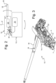
Figure 2 shows a block diagram of an installation comprising a loading system obtained in accordance with an exemplary embodiment of the present invention. -
Figure 3 shows a partial perspective rear top view of the installation comprising the loading system shown in the preceding figures. -
Figure 4 shows a partially transparent perspective view, magnified compared withFigure 3 , of an ammunition feeding assembly for the installation shown in the preceding figures. -
Figure 5 shows a perspective view, further magnified compared withFigure 3 , concerning an ammunition transfer device for the feeding assembly shown inFigure 4 . -
Figure 6 shows a partially transparent perspective view, further magnified compared withFigure 3 , concerning an ammunition conveying guide of the feeding assembly shown inFigure 4 . -
Figures 7 and 8 show, respectively, side views and perspective of the feeding mechanism of the feeding assembly shown in the preceding figures, which includes a chain. These figures also show ammunition pushing members. -
Figure 8a is a schematic view that shows how the chain is guided along its path, in particular by rollers of the chain itself, shown in the preceding figures. -
Figures 8b and 8c are views similar to those ofFigures 7 and 8 , which show an implementation variant of the previously shown chain. -
Figures 8d and 8e are views showing one possible and illustrative linking method that can be adopted for the links of the chain shown inFigures 7, 8 and 8a and respectively, of the one shown inFigures 8b and 8c . -
Figure 9 is a side view of an ammunition loading guide of the feeding assembly, which allows the transfer of ammunitions from the last section of the chain to the firearm inlet. - For completeness' sake, the following is a list of alphanumerical references and names used herein to identify parts, elements and components illustrated in the above-summarized drawings.
- Z. Traversing axis
- Y. Elevating axis
- x1. Mounting axis
- x2. Thrust axis
- W. Star element rotation axis
- P0. Magazine path
- P1. Conveying path
- P2. Loading path
- A. Ammunitions
- 1. Turret
- 10. Artillery installation
- 12. Traversing mass
- 14. Elevating mass
- 16. Firearm assembly
- 18. Barrel
- 20. Magazine
- 22. Feeding assembly
- 24. Transfer device
- 25. Inlet of the feeding assembly and conveying guide
- 26. Conveying guide
- 27. Star element
- 28. Conveying mechanism
- 29. Crank
- 30. Sliding structure
- 30a. Lateral rail portion
- 30b. Central rail portion
- 32. Conveying chain
- 34. Pushing members
- 35. Lever
- 36. Chain links
- 36a. Horizontal chain links
- 36b. Vertical chain links
- 37. Thrust spring
- 38. Sliding pins
- 38a. Lateral sliding pins
- 38b. Central sliding pins
- 39. C-shaped bodies
- 39a. Horizontal C-shaped bodies
- 39b. Vertical C-shaped bodies
- 40. Rollers
- 41. Through bores
- 41a. (First) through bores
- 41b. (Second) through bores
- 42. Gear wheels
- 46. Loading guide
- 48. Loading mechanism
- 50. Loading star elements
- With reference to
Figures 1 and 1a , numeral 1 designates as a whole a turret equipped with anartillery installation 10. -
Installation 10 is particularly suitable for installation on terrestrial vehicles, e.g. armoured vehicles such as tanks. Nevertheless, it may be used for other applications as well, e.g. aircraft, ships or fixed installations. - With reference to
Figure 2 ,installation 10 is represented by means of a block diagram, whereas inFigure 3 the construction details ofsuch installation 10 are shown in a perspective rear view. In a per se known manner,artillery installation 10 comprises a traversing portion ormass 12, an elevating portion ormass 14, and afirearm assembly 16. - Traversing
mass 12 is configured to be rotatably mounted and supported on a stationary support structure (not numbered), so as to rotate about a substantially vertical traversing (or azimuthal) axis Z. - Elevating
mass 14 is rotatably supported by traversingmass 12 about an elevating axis Y, which is substantially horizontal and perpendicular to vertical axis Z. In particular, when viewingFigure 2 , elevating axis Y substantially corresponds to an axis entering perpendicularly through the sheet plane. In a per se known manner, typically traversingmass 12 and elevatingmass 14 are mutually assembled by means of a pair of cheeks (details not shown) fixed to traversingmass 12, whereon elevation bearings are mounted, particularly at elevating axis Y). - A
firearm assembly 16 is in turn supported by elevatingmass 14. Moreover,firearm assembly 16 comprises abarrel 18 configured to fire ammunitions A. In the embodiment illustrated herein,barrel 18 is a cannon, e.g. having a calibre of 30mm. -
Installation 10 comprises also amagazine 20 configured to contain a plurality of ammunitions A to be fed tobarrel 18. In particular,magazine 20 is configured to automatically move the plurality of ammunitions A. Furthermore, ammunitions A contained in the magazine are of the type not mutually connected by links -also referred to as linkless ammunitions. -
Magazine 20 is carried by traversingmass 12 and is operatively integral therewith; in particular, as will be further explained hereinafter,magazine 20 is separate and distinct from elevatingmass 14. - In the embodiment illustrated herein,
magazine 20 has, at its outlet, a star-element conveyor of a per se known type (not numbered), which dispenses ammunitions A out of itself. -
Artillery installation 10 further comprises a feedingassembly 22 configured to transfer ammunitions A coming frommagazine 20 tobarrel 18, for such ammunitions A to be fired through the latter. - In the embodiment illustrated herein, feeding
assembly 22 is carried by elevatingmass 14 and is operatively integral therewith; in particular, unlikemagazine 20, feedingassembly 22 is separate and distinct from traversingmass 12. - Furthermore,
artillery installation 10 comprises a transfer device (or "exchanger") 24 configured to transfer ammunitions A frommagazine 20 to feedingassembly 22. - In particular,
transfer device 24 is mounted on traversingmass 12. - The following will describe further technical features of this exemplary embodiment of the present invention.
- In the implementation example illustrated herein,
transfer device 24 is mounted in proximity to the elevating axis Y. - As will be described in more detail below, also with reference to some preferred and optional technical features of the present invention, due to this arrangement of
transfer device 24 the mutual arrangement betweentransfer device 24, carried by traversingmass 12, andinlet 25 of feedingassembly 22, carried by elevatingmass 14, always remains substantially the same for any angle of elevation assumed by elevatingmass 14 relative to traversingmass 12 about elevating axis Y; therefore, ammunitions A can be conveyed frommagazine 20 to barrel 18 (through feeding assembly 22) in any mutual operating condition of traversingmass 12 and elevatingmass 14 ofartillery installation 10. - With particular reference to
Figure 4 , there is shown a magnified view of feedingassembly 22 visible in the preceding figures. - Feeding
assembly 22 comprises a conveyingguide 26 mounted on elevatingmass 14 and defining a path for transporting ammunitions A fromtransfer device 24 towardsbarrel 18. In the illustrated embodiment, the inlet of feedingassembly 22 substantially coincides with the inlet of conveyingguide 26, and both are designated by thesame reference numeral 25. - In particular,
inlet 25 of conveyingguide 26, whereat ammunitions A coming frommagazine 20 are made to arrive via a star element, e.g. a three-lobed one (not numbered inFigure 4 ), is situated in the vicinity of e elevating axis Y. Ammunitions A are intended to enter - and subsequently slide - therein with their side facing conveyingduct 26. As will be further described below, conveyingguide 26 is advantageously provided as a rigid conduit. - With particular reference to
Figures 4 and6 , conveyingguide 26 defines an open path, in particular a path shaped as a whole as a horizontally turned J. Moreover, the path defined by conveyingguide 26 extends in three dimensions in space and, being compact, makes it possible to reduce the total transversal and lateral dimensions of feedingassembly 22. - The rigid conduit formed by conveying
guide 26 is, for example, implemented as an open channel in which ammunitions A can slide. In particular, such rigid conduit has a substantially rectangular cross-section, suitable for receiving ammunitions A with their side facing forwards and for directing them towardsbarrel 18. Furthermore, said conveying conduit or channel is rigid. -
Transfer device 24 is configured to pick up ammunitions A as they exitmagazine 20 and supply them toinlet 25 of conveyingguide 26. - In
Figures 5 and6 , for completeness' sake, arrows schematically indicate the path followed by ammunitions A betweenmagazine 20 and conveyingguide 26. In particular, the arrow designated as P0 indicates the magazine path initially followed by ammunitions A exitingmagazine 20, which are then picked up bytransfer device 24. The arrow designated as P1 indicates the conveyance path followed by ammunitions A going through conveyingguide 26. As shown more clearly inFigure 6 , conveyance path P1 is substantially curvilinear and bends upwards, rotating by about 180°, thus "overturning" the ammunitions from their previous orientation atinlet 25 of conveyingguide 26. -
Transfer device 24 additionally comprises astar element 27, in particular a three-lobed one, rotatably supported about a rotation axis W situated in proximity to the elevating axis Y. In the implementation example illustrated herein,star element 27 is aligned with feedingassembly 22. -
Multi-lobed star element 27 is configured to rotate and pick up ammunitions A exitingmagazine 20 and supply them toinlet 25 of feedingassembly 22, and in particular to the conduit formed by conveyingguide 26, for moving them towardsbarrel 18. As can be seen, ammunitions A are picked up laterally bystar element 27 from the outlet ofmagazine 20, and are then delivered toinlet 25 of conveying guide 26 (in particular, to the inlet of the rigid conduit defined by the latter). -
Inlet 25 of conveying guide 26 (e.g. the inlet of the rigid conduit defined by the latter) is located at the elevating axis Y, being in particular crossed transversally by the latter. - Preferably, rotation axis W is substantially parallel to elevating axis Y; in the embodiment illustrated herein, the distance between rotation axis W and elevating axis Y is such that, in at least a part of the rotation path of
star element 27, the centre of ammunition A to be picked up bystar element 27 lies substantially on elevating axis Y. - In particular, the rotation axis W is spaced apart vertically (i.e. along the direction of the traversing axis Z) from elevating axis Y.
- According to a further embodiment,
transfer device 24 may advantageously be driven by a motor, e.g. via a gear transmission that controls the rotation ofstar element 27 about rotation axis W. - Feeding
assembly 22 further comprises a conveyingmechanism 28 configured to push ammunitions A along conveyingguide 26. In particular, conveyingmechanism 28 may be driven by means of a motor (not shown) and/or manually, e.g. by means of acrank 29. - According to one possible embodiment of the present invention, the transmission of the motion from conveying
mechanism 28 in elevatingmass 14 to transferdevice 24 in traversingmass 12 may occur through a mechanical connection consisting of a differential gear (not shown in the drawing) that ensures synchronized motion. - Conveying
mechanism 28 comprises a hollow slidingstructure 30 and a conveyingchain 32 sliding in the cavity defined by slidingstructure 30. Some exemplary technical features of conveyingchain 32 are visible in more detail inFigures 7, 8 and 8a . - Conveying
mechanism 28 comprises also a plurality of pushingmembers 34 sliding in conveyingguide 26 and carried by conveyingchain 32. Each one of pushingmembers 34 is configured for pushing a respective ammunition A adjacent thereto, which is guided by conveyingguide 26. - Sliding
structure 30 extends substantially parallel to conveyingguide 26. In particular, slidingstructure 30 is fixed to conveyingguide 26, e.g. being surrounded along at least a part of its extension by conveyingguide 26. - Furthermore, as will be described more in detail hereinafter, preferably sliding
structure 30 is essentially a rail in which conveyingchain 32 slides and from/by which pushingmembers 34 are suspended and/or supported, which then extend and slide inuconveying guide 26. In particular, the rail comprises a plurality ofrail portions - Conveying
chain 32 forms a closed loop and is configured to transmit a forward motion to pushingmembers 34 mounted thereon. Also, conveyingchain 32 comprises a plurality ofchain links 36 mutually connected in an articulated manner. More in detail, chain links 36 can move, in particular by rotating in different planes, in order to follow the path delimited by conveyingguide 26. - In the embodiment illustrated herein, each one of pushing
members 34 is shaped substantially as a widened fork, the neck of which - which protrudes and is supported by respective chain link 36 - branches off laterally into two arms. - In the embodiment illustrated herein, each one of
chain links 36 substantially defines a closed-loop shape (e.g. wherein the closed loop forms a substantially rectangular or square shape). - As shown in detail in
Figures 7 and 8 , each closed loop defined by eachchain link 36 lies in a plane perpendicular to the plane in which the previous and/ornext chain link 36 lies. In this regard, by way of example, inFigure 7 ,reference number Figure 7 , thelink 36a is joined to link 36b by means of a connection that - as will be described in more detail below - provides such two components with three degrees of freedom, thus differing from a traditional chain (e.g. a bicycle chain) . - In particular, pushing
members 34 are arranged along conveyingchain 32 spaced out by a predetermined distance, so that between two pushing members 34 a corresponding ammunition A can be housed, which must be guidedly transported along conveyingguide 26. In particular, each one of pushingmembers 34 is mounted on a respective chain link 36 at predetermined intervals (e.g. at regular and periodic intervals) along conveyingchain 32. More particularly, each one of pushingmembers 34 is mounted after a predefined number of successive chain links 36, depending on the diameter or calibre of the ammunition A to be conveyed. - Furthermore, each pushing
member 34 is fixedly mounted to the respective chain link 36 along a mounting axis x1 substantially perpendicular to conveyingchain 32. - As it will be further described below, chain links 36 carry respective sliding
pins 38 on their sides. - In particular, sliding
pins 38rotatably support rollers 40 around themselves. Sliding pins 38 slide, preferably viarollers 40, within slidingstructure 30, which, as aforementioned, substantially defines a rail along which conveyingchain 32 is configured to slide and/or by which it is configured to be supported. - In particular, each
roller 40 carried by the respective slidingpin 38 engages into arespective rail portion structure 30. In the embodiment illustrated herein, chain links 36 to which ppushingmembers 34 are mounted have no associated sliding pin (and roller). - As illustrated in
Figure 8a , each one ofrail portions rollers 40 preferably carried by respective slidingpins 38 protruding fromchain links 36, so as to guide andsupport conveying chain 32 as it moves in space. - More in detail, still with reference to the embodiment illustrated by way of example in
Figures 7 and 8 , each one of thehorizontal chain links 36a has alateral sliding pin 38a that protrudes from laterally opposite sides. The ends oflateral sliding pin 38a engage, under the sliding action ofrollers 40, into correspondinglateral rail portions 30a of slidingstructure 30. - Conversely, each
vertical chain link 36b (e.g. when it lacks and does not support an associated pushing member 34) has respective central slidingpin 38b protruding from conveyingchain 32 on the side axially opposite to the side from which pushingmembers 34 extend. The end of central slidingpin 38b slidably engages into a correspondingcentral rail portion 30b of slidingstructure 30. - In the embodiment illustrated herein, each pushing
member 34 is supported along its mounting axis x1 through the interposition of anadditional roller 40 between it andchain link 36. In particular, at oneend roller 40 is rotatably mounted tochain link 36, while at the other end it is rotatably integral with pushingmember 34. - With reference to
Figures 8b and 8c , there is shown a further implementation variant of conveyingchain 32. Compared with the conveying chain illustrated inFigures 7, 8 and 8a , alever 35 is associated with each pushingmember 34. In particular,lever 35 is mounted to pushingmember 34 and is elastically stressed so that it abuts against ammunition A. In this manner, considering that when viewingFigures 8b and 8c the ammunition feeding direction is from right to left, each ammunition A is pushed against the previous pushingmember 34 bylever 35 mounted to the next pushingmember 34. - Moreover,
lever 35 is moved angularly away from pushingmember 34 about a thrust axis x2, e.g. substantially perpendicular to mounting axis x1. In particular, athrust spring 37 is provided, which is mounted between pushingmember 34 andlever 35.Thrust spring 37 abuts on pushingmember 34 at one end and onlever 35 at the other end. In the implementation variant illustrated herein, thrustspring 37 is, advantageously, a torsion spring. - With reference to
Figures 8d and 8e , there is shown an exemplary way of linking chain links 36. In the embodiment illustrated herein, chain links 36 consist of a C-shapedbody 39 whose ends are crossed by a respective slidingpin 38; in other words, the closed-loop shape of eachchain link 36 is defined by C-shapedbody 39 and by a respective slidingpin 38. - In addition, still with reference to
Figures 8d and 8e , eachchain link 36 is connected toadjacent chain link 36 by means of respective slidingpin 38, which fits through a throughbore 41 formed in the intermediate portion of C-shapedbody 39 belonging toadjacent chain link 36, situated between the ends ofchain link 36. For example, eachvertical link 36b is connected to adjacenthorizontal link 36a by means of central slidingpin 38b that fits through the (first) throughbore 41a formed in the intermediate portion of horizontal C-shapedbody 39a. Vice versa, eachhorizontal link 36a is connected to adjacentvertical link 36b by means of lateral slidingpin 38a that fits through the (second) throughbore 41b formed in the intermediate portion of vertical C-shapedbody 39b. - With particular reference to
Figures 6 and9 , conveyingmechanism 28 further comprises a pair ofgear wheels 42 cooperating with conveyingchain 32 in order to move it along slidingstructure 30. In particular, atgear wheels 42 slidingstructure 30 is interrupted and allows slidingpins 38 ofchain links 36 to engage with the crown formed by each one ofgear wheels 42 in order to achieve the movement of conveyingchain 32. More particularly,lateral sliding pins 38a are engaged between successive teeth ofgear wheels 42. Even more particularly, central slidingpins 38b are engaged into an annular groove (not visible in the drawings) provided on eachgear wheel 42; this limits the lateral displacement of chain links 36. - With particular reference to
Figure 9 , feedingassembly 22 comprises also aloading guide 46 situated between conveyingguide 26 andbarrel 18. More in detail, loadingguide 46 is adjacent to the outlet of conveyingguide 26 at one end and adjacent to the inlet ofbarrel 18 at the other end. - In the embodiment illustrated herein, loading
guide 46 defines a substantially straight and ascending loading path P2 for the ammunitions coming from conveyingguide 26 and directed towardsbarrel 18. - Feeding
assembly 22 further comprises aloading mechanism 48 configured to push the ammunitions A along loadingguide 46 and towards the inlet ofbarrel 18. In particular,loading mechanism 48 comprises a plurality of loadingstar elements 50 arranged in series and mutually adjacent. Loadingstar elements 50 are configured to rotate and engage in succession ammunitions A which have come sideways from conveyingguide 26 and which have arrived - still with a lateral orientation - atloading guide 46, so as to cause them to advance up to the inlet ofbarrel 18. - In particular,
loading mechanism 48 is rigidly connected tofirearm assembly 16, so that the actuation of the whole feeding assembly is regulated byfirearm assembly 16 itself. - Of course, without prejudice to the principle of the invention, the forms of embodiment and the implementation details may be extensively varied from those described and illustrated herein by way of non-limiting example, without however departing from the scope of the invention as set out in the appended claims.
Claims (7)
- Linkless ammunition loading installation (10) comprising:- a traversing portion (12) configured to be rotatably mounted and supported on a stationary support structure, so as to rotate about a traversing axis (Z),- an elevating portion (14) rotatably supported by said traversing portion (12) about an elevating axis (Y) perpendicular to the traversing axis (Z),- a firearm assembly (16) supported by the elevating portion (14) and comprising a barrel (18) configured to fire ammunitions (A) through itself,- a magazine (20) carried by said traversing portion (12) and configured to contain a plurality of linkless ammunitions (A) to be fed to said barrel (18),- a feeding assembly (22) configured to transfer the linkless ammunitions (A) from said magazine (20) to said barrel (18) for firing said linkless ammunitions (A), said feeding assembly (22) being carried by said elevating portion (14), and- a transfer device (24) configured to transfer said linkless ammunitions (A) from said magazine (20) to said feeding assembly (22);wherein said magazine (20) is separate and distinct from said elevating portion (14), and said feeding assembly (22) is separate and distinct from said traversing portion (12); andwherein said transfer device (24) is mounted on said traversing portion (12) and comprises a star element (27) rotatably supported about a rotation axis (W);wherein said feeding assembly (22) comprises a conveying guide (26) mounted on said elevating portion (14) and defining a path for transporting said linkless ammunitions (A) from said transfer device (24) towards said barrel (18);said installation being characterized in that said rotation axis (W) is parallel to said elevation axis (Y);in that the centre of ammunition (A) to be picked up by said star element (27) lies on said elevating axis (Y) during a part of the rotation path of said star element (27);in that said rotation axis (W) is spaced apart from said elevating axis (Y) along the direction of said traversing axis (Z);in that said conveying guide (26) is provided as a rigid conduit;in that said conveying guide (26) has an inlet (25) which is located at said elevating axis (Y); andin that said inlet (25) is crossed transversally by said elevating axis (Y).
- Installation according to claim 1, wherein said star element (27) is aligned with the feeding assembly (22) for rotating and picking up said linkless ammunitions (A) exiting said magazine (20) and supplying them to the inlet (25) of said feeding assembly (22).
- Installation according to any of the preceding claims, wherein said feeding assembly (22) further comprises a conveying mechanism (28) configured to push said linkless ammunitions (A) along said conveying guide (26).
- Installation according to claim 3, wherein said conveying mechanism (28) comprises:- a hollow sliding structure (30),- a conveying chain (32) sliding in the cavity defined by said sliding structure (30), and- a plurality of pushing members (34) sliding in said conveying guide (26) and carried by the conveying chain (32), each one of said pushing members (34) being configured for pushing a respective linkless ammunition (A) adjacent thereto.
- Installation according to claim 4, wherein said sliding structure (30) comprises a guide (30a, 30b) in which said conveying chain (32) slides and from/by which said pushing members (34) are suspended and/or supported.
- Installation according to any one of the preceding claims, wherein said feeding assembly (22) further comprises a loading guide (46) situated between said conveying guide (26) and said barrel (18).
- Installation according to claim 6, wherein said feeding assembly (22) further comprises a loading mechanism (48) configured to push said linkless ammunitions (A) along said loading guide (46) towards the inlet of said barrel (18).
Applications Claiming Priority (2)
| Application Number | Priority Date | Filing Date | Title |
|---|---|---|---|
| IT102021000014819A IT202100014819A1 (en) | 2021-06-08 | 2021-06-08 | Facility equipped with an ammunition loading system. |
| PCT/IB2022/055273 WO2022259131A1 (en) | 2021-06-08 | 2022-06-07 | Loading system for linkless ammunition |
Publications (3)
| Publication Number | Publication Date |
|---|---|
| EP4352443A1 EP4352443A1 (en) | 2024-04-17 |
| EP4352443B1 true EP4352443B1 (en) | 2025-04-23 |
| EP4352443C0 EP4352443C0 (en) | 2025-04-23 |
Family
ID=77519664
Family Applications (1)
| Application Number | Title | Priority Date | Filing Date |
|---|---|---|---|
| EP22732334.2A Active EP4352443B1 (en) | 2021-06-08 | 2022-06-07 | Loading system for linkless ammunition |
Country Status (8)
| Country | Link |
|---|---|
| US (1) | US12287169B2 (en) |
| EP (1) | EP4352443B1 (en) |
| KR (1) | KR20240028349A (en) |
| CN (1) | CN117859038A (en) |
| BR (1) | BR112023025518A2 (en) |
| CA (1) | CA3218622A1 (en) |
| IT (1) | IT202100014819A1 (en) |
| WO (1) | WO2022259131A1 (en) |
Citations (2)
| Publication number | Priority date | Publication date | Assignee | Title |
|---|---|---|---|---|
| US1332060A (en) * | 1918-10-15 | 1920-02-24 | Pacilli Leonardo | Recoll-operated ordnance |
| US10132581B2 (en) * | 2012-06-05 | 2018-11-20 | Rafael Advanced Defense Systems, Ltd. | Belt/metallic link chain loaded ammunition feeder in a remote controlled weapon station |
Family Cites Families (13)
| Publication number | Priority date | Publication date | Assignee | Title |
|---|---|---|---|---|
| US2971438A (en) * | 1951-05-11 | 1961-02-14 | Paul L Fox | Off-mount magazine ammunition transfer mechanism |
| CH379969A (en) * | 1959-02-13 | 1964-07-15 | Oerlikon Buehrle Ag | Ammunition magazine for automatic firearms |
| US4244271A (en) * | 1979-01-10 | 1981-01-13 | The United States Of America As Represented By The Secretary Of The Air Force | Ammunition feed timing mechanism |
| US4440061A (en) * | 1981-04-20 | 1984-04-03 | Paccar Inc. | Gun traverse apparatus |
| US4492144A (en) * | 1982-04-05 | 1985-01-08 | General Electric Company | Transport mechanism for ammunition |
| US4681018A (en) * | 1982-11-26 | 1987-07-21 | Heckler & Koch Gmbh | Cartridge feed mechanism |
| US4840108A (en) * | 1987-05-08 | 1989-06-20 | Werkzeugmaschinenfabrick Oerlikon-Buhrle Ag | Apparatus for the infeed of ammunition from an ammunition container to an automatic firing weapon |
| EP0405177A1 (en) * | 1989-06-30 | 1991-01-02 | Werkzeugmaschinenfabrik Oerlikon-Bührle AG | Device for feeding with cartridges a gun which is moveable in elevation |
| JPH081356B2 (en) * | 1993-11-29 | 1996-01-10 | 防衛庁技術研究本部長 | Ammunition supply device |
| SE513006C2 (en) * | 1999-01-20 | 2000-06-19 | Bofors Weapon Sys Ab | Method and apparatus for handling artillery grenades when loading artillery pieces |
| FR2823176B1 (en) * | 2001-04-06 | 2003-07-04 | Giat Ind Sa | METHOD AND SYSTEM FOR AUTOMATICALLY LOADING A WEAPON MOUNTED ON A VESSEL |
| US8215225B1 (en) * | 2010-06-03 | 2012-07-10 | The United States Of America As Represented By The Secretary Of The Army | Large caliber autoloader |
| BE1023730B1 (en) * | 2015-12-17 | 2017-06-30 | Cockerill Maintenance & Ingenierie S.A. | MEDIUM SIZE FEEDING DEVICE WITH ROTATING PLATE |
-
2021
- 2021-06-08 IT IT102021000014819A patent/IT202100014819A1/en unknown
-
2022
- 2022-06-07 CA CA3218622A patent/CA3218622A1/en active Pending
- 2022-06-07 BR BR112023025518A patent/BR112023025518A2/en unknown
- 2022-06-07 WO PCT/IB2022/055273 patent/WO2022259131A1/en not_active Ceased
- 2022-06-07 CN CN202280041065.3A patent/CN117859038A/en active Pending
- 2022-06-07 KR KR1020237044129A patent/KR20240028349A/en active Pending
- 2022-06-07 US US18/566,040 patent/US12287169B2/en active Active
- 2022-06-07 EP EP22732334.2A patent/EP4352443B1/en active Active
Patent Citations (2)
| Publication number | Priority date | Publication date | Assignee | Title |
|---|---|---|---|---|
| US1332060A (en) * | 1918-10-15 | 1920-02-24 | Pacilli Leonardo | Recoll-operated ordnance |
| US10132581B2 (en) * | 2012-06-05 | 2018-11-20 | Rafael Advanced Defense Systems, Ltd. | Belt/metallic link chain loaded ammunition feeder in a remote controlled weapon station |
Also Published As
| Publication number | Publication date |
|---|---|
| CN117859038A (en) | 2024-04-09 |
| US12287169B2 (en) | 2025-04-29 |
| CA3218622A1 (en) | 2022-12-15 |
| BR112023025518A2 (en) | 2024-02-27 |
| IT202100014819A1 (en) | 2022-12-08 |
| KR20240028349A (en) | 2024-03-05 |
| US20240280338A1 (en) | 2024-08-22 |
| EP4352443A1 (en) | 2024-04-17 |
| WO2022259131A1 (en) | 2022-12-15 |
| EP4352443C0 (en) | 2025-04-23 |
Similar Documents
| Publication | Publication Date | Title |
|---|---|---|
| US8833228B2 (en) | System and a method for protected reloading of a remote controlled weapon station | |
| US5103712A (en) | Ammunition reloading system and operating method | |
| US4326446A (en) | Linkage of actuating system for elevating gun mount | |
| US5392685A (en) | Automatic cannon with carbioid-shaped shell chamber path | |
| US4381693A (en) | Military equipment comprising a turret carrying an external large caliber gun | |
| US9777976B2 (en) | Spent cartridges router | |
| JPH02133800A (en) | Projectile-feed device | |
| US12287169B2 (en) | Installation provided with linkless ammunition loading system | |
| US6272967B1 (en) | Modular ammunition storage and retrieval system | |
| US4344350A (en) | Crossfeeder | |
| JPS58214795A (en) | Feeder for ammunition of automatic firearm | |
| US3170372A (en) | Loader and magazine mechanism | |
| US5289754A (en) | Redundant ammunition flow device | |
| US3169445A (en) | Magazine mechanism | |
| US7836812B2 (en) | Propellant charge feed or supply means | |
| KR102940763B1 (en) | Automatic reloading device for a weapon with dual ammunition magazine feed, and weapon system comprising it | |
| EP0038847A1 (en) | Two stage shell feeding apparatus with shell feeding path control | |
| US2905056A (en) | Feeder device for the automatic loading of guns | |
| HK40108351A (en) | Loading system for linkless ammunition | |
| US3596557A (en) | Positioning device for correcting mislinked ammunition | |
| RU2850013C1 (en) | Automatic gun loading system | |
| EP1216392B1 (en) | Ammunition handling system | |
| EP4698841A1 (en) | Magazine for an artillery installation, provided with a guide structure | |
| KR0133680Y1 (en) | Shot feeder | |
| EP2856065A1 (en) | Belt/metallic link chain loaded ammunition feeder in a remote controlled weapon station |
Legal Events
| Date | Code | Title | Description |
|---|---|---|---|
| STAA | Information on the status of an ep patent application or granted ep patent |
Free format text: STATUS: UNKNOWN |
|
| STAA | Information on the status of an ep patent application or granted ep patent |
Free format text: STATUS: THE INTERNATIONAL PUBLICATION HAS BEEN MADE |
|
| PUAI | Public reference made under article 153(3) epc to a published international application that has entered the european phase |
Free format text: ORIGINAL CODE: 0009012 |
|
| STAA | Information on the status of an ep patent application or granted ep patent |
Free format text: STATUS: REQUEST FOR EXAMINATION WAS MADE |
|
| 17P | Request for examination filed |
Effective date: 20231227 |
|
| AK | Designated contracting states |
Kind code of ref document: A1 Designated state(s): AL AT BE BG CH CY CZ DE DK EE ES FI FR GB GR HR HU IE IS IT LI LT LU LV MC MK MT NL NO PL PT RO RS SE SI SK SM TR |
|
| DAV | Request for validation of the european patent (deleted) | ||
| DAX | Request for extension of the european patent (deleted) | ||
| GRAP | Despatch of communication of intention to grant a patent |
Free format text: ORIGINAL CODE: EPIDOSNIGR1 |
|
| STAA | Information on the status of an ep patent application or granted ep patent |
Free format text: STATUS: GRANT OF PATENT IS INTENDED |
|
| INTG | Intention to grant announced |
Effective date: 20241120 |
|
| GRAS | Grant fee paid |
Free format text: ORIGINAL CODE: EPIDOSNIGR3 |
|
| GRAA | (expected) grant |
Free format text: ORIGINAL CODE: 0009210 |
|
| STAA | Information on the status of an ep patent application or granted ep patent |
Free format text: STATUS: THE PATENT HAS BEEN GRANTED |
|
| AK | Designated contracting states |
Kind code of ref document: B1 Designated state(s): AL AT BE BG CH CY CZ DE DK EE ES FI FR GB GR HR HU IE IS IT LI LT LU LV MC MK MT NL NO PL PT RO RS SE SI SK SM TR |
|
| REG | Reference to a national code |
Ref country code: GB Ref legal event code: FG4D |
|
| REG | Reference to a national code |
Ref country code: CH Ref legal event code: EP |
|
| REG | Reference to a national code |
Ref country code: DE Ref legal event code: R096 Ref document number: 602022013616 Country of ref document: DE |
|
| REG | Reference to a national code |
Ref country code: IE Ref legal event code: FG4D |
|
| U01 | Request for unitary effect filed |
Effective date: 20250515 |
|
| U07 | Unitary effect registered |
Designated state(s): AT BE BG DE DK EE FI FR IT LT LU LV MT NL PT RO SE SI Effective date: 20250521 |
|
| U20 | Renewal fee for the european patent with unitary effect paid |
Year of fee payment: 4 Effective date: 20250603 |
|
| REG | Reference to a national code |
Ref country code: GR Ref legal event code: EP Ref document number: 20250401464 Country of ref document: GR Effective date: 20250808 |
|
| PG25 | Lapsed in a contracting state [announced via postgrant information from national office to epo] |
Ref country code: ES Free format text: LAPSE BECAUSE OF FAILURE TO SUBMIT A TRANSLATION OF THE DESCRIPTION OR TO PAY THE FEE WITHIN THE PRESCRIBED TIME-LIMIT Effective date: 20250423 |
|
| PG25 | Lapsed in a contracting state [announced via postgrant information from national office to epo] |
Ref country code: NO Free format text: LAPSE BECAUSE OF FAILURE TO SUBMIT A TRANSLATION OF THE DESCRIPTION OR TO PAY THE FEE WITHIN THE PRESCRIBED TIME-LIMIT Effective date: 20250723 |
|
| PG25 | Lapsed in a contracting state [announced via postgrant information from national office to epo] |
Ref country code: PL Free format text: LAPSE BECAUSE OF FAILURE TO SUBMIT A TRANSLATION OF THE DESCRIPTION OR TO PAY THE FEE WITHIN THE PRESCRIBED TIME-LIMIT Effective date: 20250423 |
|
| PG25 | Lapsed in a contracting state [announced via postgrant information from national office to epo] |
Ref country code: HR Free format text: LAPSE BECAUSE OF FAILURE TO SUBMIT A TRANSLATION OF THE DESCRIPTION OR TO PAY THE FEE WITHIN THE PRESCRIBED TIME-LIMIT Effective date: 20250423 |
|
| PG25 | Lapsed in a contracting state [announced via postgrant information from national office to epo] |
Ref country code: RS Free format text: LAPSE BECAUSE OF FAILURE TO SUBMIT A TRANSLATION OF THE DESCRIPTION OR TO PAY THE FEE WITHIN THE PRESCRIBED TIME-LIMIT Effective date: 20250723 |
|
| PG25 | Lapsed in a contracting state [announced via postgrant information from national office to epo] |
Ref country code: IS Free format text: LAPSE BECAUSE OF FAILURE TO SUBMIT A TRANSLATION OF THE DESCRIPTION OR TO PAY THE FEE WITHIN THE PRESCRIBED TIME-LIMIT Effective date: 20250823 |
|
| PG25 | Lapsed in a contracting state [announced via postgrant information from national office to epo] |
Ref country code: SM Free format text: LAPSE BECAUSE OF FAILURE TO SUBMIT A TRANSLATION OF THE DESCRIPTION OR TO PAY THE FEE WITHIN THE PRESCRIBED TIME-LIMIT Effective date: 20250423 |
|
| PG25 | Lapsed in a contracting state [announced via postgrant information from national office to epo] |
Ref country code: CZ Free format text: LAPSE BECAUSE OF FAILURE TO SUBMIT A TRANSLATION OF THE DESCRIPTION OR TO PAY THE FEE WITHIN THE PRESCRIBED TIME-LIMIT Effective date: 20250423 |
|
| PG25 | Lapsed in a contracting state [announced via postgrant information from national office to epo] |
Ref country code: SK Free format text: LAPSE BECAUSE OF FAILURE TO SUBMIT A TRANSLATION OF THE DESCRIPTION OR TO PAY THE FEE WITHIN THE PRESCRIBED TIME-LIMIT Effective date: 20250423 |
|
| REG | Reference to a national code |
Ref country code: CH Ref legal event code: H13 Free format text: ST27 STATUS EVENT CODE: U-0-0-H10-H13 (AS PROVIDED BY THE NATIONAL OFFICE) Effective date: 20260127 |
|
| PG25 | Lapsed in a contracting state [announced via postgrant information from national office to epo] |
Ref country code: MC Free format text: LAPSE BECAUSE OF FAILURE TO SUBMIT A TRANSLATION OF THE DESCRIPTION OR TO PAY THE FEE WITHIN THE PRESCRIBED TIME-LIMIT Effective date: 20250423 |
|
| PLBE | No opposition filed within time limit |
Free format text: ORIGINAL CODE: 0009261 |
|
| STAA | Information on the status of an ep patent application or granted ep patent |
Free format text: STATUS: NO OPPOSITION FILED WITHIN TIME LIMIT |
|
| REG | Reference to a national code |
Ref country code: CH Ref legal event code: L10 Free format text: ST27 STATUS EVENT CODE: U-0-0-L10-L00 (AS PROVIDED BY THE NATIONAL OFFICE) Effective date: 20260304 |
|
| 26N | No opposition filed |
Effective date: 20260126 |
|
| PG25 | Lapsed in a contracting state [announced via postgrant information from national office to epo] |
Ref country code: IE Free format text: LAPSE BECAUSE OF NON-PAYMENT OF DUE FEES Effective date: 20250607 |
|
| PG25 | Lapsed in a contracting state [announced via postgrant information from national office to epo] |
Ref country code: CH Free format text: LAPSE BECAUSE OF NON-PAYMENT OF DUE FEES Effective date: 20250630 |
|
| U20 | Renewal fee for the european patent with unitary effect paid |
Year of fee payment: 5 Effective date: 20260331 |
|
| PGFP | Annual fee paid to national office [announced via postgrant information from national office to epo] |
Ref country code: GR Payment date: 20260618 Year of fee payment: 5 |
|
| PGFP | Annual fee paid to national office [announced via postgrant information from national office to epo] |
Ref country code: TR Payment date: 20260603 Year of fee payment: 5 |
|
| PG25 | Lapsed in a contracting state [announced via postgrant information from national office to epo] |
Ref country code: CY Free format text: LAPSE BECAUSE OF FAILURE TO SUBMIT A TRANSLATION OF THE DESCRIPTION OR TO PAY THE FEE WITHIN THE PRESCRIBED TIME-LIMIT Effective date: 20250423 |