EP4352339B1 - A method and a system for monitoring and on-line determining of a calorific value of solid fuel that is currently combusted in a boiler - Google Patents
A method and a system for monitoring and on-line determining of a calorific value of solid fuel that is currently combusted in a boiler Download PDFInfo
- Publication number
- EP4352339B1 EP4352339B1 EP22732261.7A EP22732261A EP4352339B1 EP 4352339 B1 EP4352339 B1 EP 4352339B1 EP 22732261 A EP22732261 A EP 22732261A EP 4352339 B1 EP4352339 B1 EP 4352339B1
- Authority
- EP
- European Patent Office
- Prior art keywords
- mill
- boiler
- solid fuel
- calorific value
- operational data
- Prior art date
- Legal status (The legal status is an assumption and is not a legal conclusion. Google has not performed a legal analysis and makes no representation as to the accuracy of the status listed.)
- Active
Links
Images


Classifications
-
- F—MECHANICAL ENGINEERING; LIGHTING; HEATING; WEAPONS; BLASTING
- F01—MACHINES OR ENGINES IN GENERAL; ENGINE PLANTS IN GENERAL; STEAM ENGINES
- F01K—STEAM ENGINE PLANTS; STEAM ACCUMULATORS; ENGINE PLANTS NOT OTHERWISE PROVIDED FOR; ENGINES USING SPECIAL WORKING FLUIDS OR CYCLES
- F01K13/00—General layout or general methods of operation of complete plants
- F01K13/02—Controlling, e.g. stopping or starting
-
- F—MECHANICAL ENGINEERING; LIGHTING; HEATING; WEAPONS; BLASTING
- F23—COMBUSTION APPARATUS; COMBUSTION PROCESSES
- F23C—METHODS OR APPARATUS FOR COMBUSTION USING FLUID FUEL OR SOLID FUEL SUSPENDED IN A CARRIER GAS OR AIR
- F23C1/00—Combustion apparatus specially adapted for combustion of two or more kinds of fuel simultaneously or alternately, at least one kind of fuel being either a fluid fuel or a solid fuel suspended in a carrier gas or air
- F23C1/12—Combustion apparatus specially adapted for combustion of two or more kinds of fuel simultaneously or alternately, at least one kind of fuel being either a fluid fuel or a solid fuel suspended in a carrier gas or air gaseous and pulverulent fuel
-
- F—MECHANICAL ENGINEERING; LIGHTING; HEATING; WEAPONS; BLASTING
- F23—COMBUSTION APPARATUS; COMBUSTION PROCESSES
- F23D—BURNERS
- F23D1/00—Burners for combustion of pulverulent fuel
-
- F—MECHANICAL ENGINEERING; LIGHTING; HEATING; WEAPONS; BLASTING
- F23—COMBUSTION APPARATUS; COMBUSTION PROCESSES
- F23G—CREMATION FURNACES; CONSUMING WASTE PRODUCTS BY COMBUSTION
- F23G5/00—Incineration of waste; Incinerator constructions; Details, accessories or control therefor
- F23G5/02—Incineration of waste; Incinerator constructions; Details, accessories or control therefor with pretreatment
- F23G5/033—Incineration of waste; Incinerator constructions; Details, accessories or control therefor with pretreatment comminuting or crushing
-
- F—MECHANICAL ENGINEERING; LIGHTING; HEATING; WEAPONS; BLASTING
- F23—COMBUSTION APPARATUS; COMBUSTION PROCESSES
- F23G—CREMATION FURNACES; CONSUMING WASTE PRODUCTS BY COMBUSTION
- F23G7/00—Incinerators or other apparatus for consuming industrial waste, e.g. chemicals
- F23G7/10—Incinerators or other apparatus for consuming industrial waste, e.g. chemicals of field or garden waste or biomasses
- F23G7/105—Incinerators or other apparatus for consuming industrial waste, e.g. chemicals of field or garden waste or biomasses of wood waste
-
- G—PHYSICS
- G01—MEASURING; TESTING
- G01K—MEASURING TEMPERATURE; MEASURING QUANTITY OF HEAT; THERMALLY-SENSITIVE ELEMENTS NOT OTHERWISE PROVIDED FOR
- G01K17/00—Measuring quantity of heat
-
- G—PHYSICS
- G01—MEASURING; TESTING
- G01N—INVESTIGATING OR ANALYSING MATERIALS BY DETERMINING THEIR CHEMICAL OR PHYSICAL PROPERTIES
- G01N33/00—Investigating or analysing materials by specific methods not covered by groups G01N1/00 - G01N31/00
- G01N33/22—Fuels; Explosives
- G01N33/222—Solid fuels, e.g. coal
-
- G—PHYSICS
- G06—COMPUTING OR CALCULATING; COUNTING
- G06N—COMPUTING ARRANGEMENTS BASED ON SPECIFIC COMPUTATIONAL MODELS
- G06N3/00—Computing arrangements based on biological models
- G06N3/02—Neural networks
- G06N3/04—Architecture, e.g. interconnection topology
- G06N3/044—Recurrent networks, e.g. Hopfield networks
- G06N3/0442—Recurrent networks, e.g. Hopfield networks characterised by memory or gating, e.g. long short-term memory [LSTM] or gated recurrent units [GRU]
-
- G—PHYSICS
- G06—COMPUTING OR CALCULATING; COUNTING
- G06N—COMPUTING ARRANGEMENTS BASED ON SPECIFIC COMPUTATIONAL MODELS
- G06N3/00—Computing arrangements based on biological models
- G06N3/02—Neural networks
- G06N3/08—Learning methods
- G06N3/09—Supervised learning
-
- F—MECHANICAL ENGINEERING; LIGHTING; HEATING; WEAPONS; BLASTING
- F22—STEAM GENERATION
- F22B—METHODS OF STEAM GENERATION; STEAM BOILERS
- F22B35/00—Control systems for steam boilers
- F22B35/18—Applications of computers to steam-boiler control
-
- F—MECHANICAL ENGINEERING; LIGHTING; HEATING; WEAPONS; BLASTING
- F23—COMBUSTION APPARATUS; COMBUSTION PROCESSES
- F23G—CREMATION FURNACES; CONSUMING WASTE PRODUCTS BY COMBUSTION
- F23G2209/00—Specific waste
- F23G2209/26—Biowaste
-
- F—MECHANICAL ENGINEERING; LIGHTING; HEATING; WEAPONS; BLASTING
- F23—COMBUSTION APPARATUS; COMBUSTION PROCESSES
- F23N—REGULATING OR CONTROLLING COMBUSTION
- F23N2221/00—Pretreatment or prehandling
- F23N2221/10—Analysing fuel properties, e.g. density, calorific
-
- G—PHYSICS
- G06—COMPUTING OR CALCULATING; COUNTING
- G06N—COMPUTING ARRANGEMENTS BASED ON SPECIFIC COMPUTATIONAL MODELS
- G06N3/00—Computing arrangements based on biological models
- G06N3/02—Neural networks
- G06N3/08—Learning methods
Definitions
- the present invention relates to monitoring combustion of solid fuel in a boiler and to on-line determining of a calorific value of the solid fuel currently combusted in the boiler, in particular in thermal power plants.
- Thermal power plants produce electricity as a result of energy conversions.
- the main component of a thermal power plant is a steam boiler, wherein fuel is combusted (usually fossil fuel - coal or natural gas, biomass, biogas or waste).
- fuel is combusted (usually fossil fuel - coal or natural gas, biomass, biogas or waste).
- the thermal energy from the steam boiler is used to heat, evaporate and superheat steam that feeds the turbine.
- the steam-powered turbine generates mechanical energy to drive a shaft of an electric generator.
- Large power plants may be equipped with several power blocks, wherein energy production processes are carried out such that they are at least partially separate (or usually independent of each other). These processes are carried out usually by means of independent elements, such as boilers, turbines, condensers, pumps, exchangers, generators and the like.
- thermal boilers have an efficiency in the range of 70 to 94%.
- the efficiency of the boiler results from the applied solutions, wear and tear of devices, irreversibility of thermal processes and process losses resulting from imperfect control and process errors. These losses get worse along with the lifetime of the boiler, which can be up to several decades.
- various types of monitoring systems are used in thermal power plants. The monitoring systems are used to monitor the operation of the power plant, including the boiler, and to generate information on how to optimise the operation of the power plant.
- DCS Distributed Control Systems
- DCS-based automation systems are used with implemented design process characteristics of boiler operation, obtained at the time of commissioning of the power plant or partially corrected after major overhauls. These characteristics become less and less useful as the service life and associated operational and technical changes progress.
- Information about the LHV (Lower Heating Value) of the fuel is necessary to accurately optimise the operation of the boiler, but in typical systems, fuel quality analysis is carried out with a significant delay, making it impossible to use the results of this analysis in real time.
- Possible solutions require an additional investment to upgrade the boiler infrastructure. In the case of boilers which have been in operation for several decades, solutions which do not interfere with the plant's infrastructure are preferred over new investments.
- the ability to achieve the required power in the block depends on the chemical energy reserves of fuel available at the solid fuel mills. Currently, the block operator has no knowledge of the energy potential available at the mills that prepare the solid fuel fed to the boiler. Information on the current calorific value would allow the determination of energy reserves both on the currently operating mill units, as well as on units that are currently shut down but ready to be switched on in case of the need to reach high loads of the power block.
- the system according to the invention solves the problems described above.
- the solution according to the invention enables precise on-line management and optimisation of the boiler operation, as well as significantly increases the operational awareness of boiler operators.
- the object of the invention is a method for on-line monitoring and determining a calorific value of a solid fuel that is currently combusted in a boiler that comprises a combustion chamber with a steam production system, to which the solid fuel is fed from at least one mill connected to a hopper.
- the method comprises measuring, on-line during the operation of the boiler, operational data of the boiler, and operational data of at least one mill.
- the operational data of the boiler are measured by means of sensors and comprise at least one of: temperature, pressure, steam flow; wherein the operational data of the at least one mill are measured by means of sensors and comprise at least one of: mill power, air pressure upstream of the mill, solid fuel feeder revolutions, air temperature upstream of the mill, temperature of the dust-air mixture downstream of the mill.
- the method further comprises collecting historical data of measurements of the calorific value of the solid fuel and the operational data of a power block, wherein the operational data of the power block include at least one of: lower heating value, mill characteristics, fuel flow rate and boiler efficiency, operational parameters of turbine, including flows, pressures and temperatures for live steam, superheated steam and secondary steam, operational data of the boiler, operational data of at least one mill, composition of exhaust gases, power of the block.
- the method also includes calculating energy balances of the steam production system, based on the collected historical data and depending on the amount of thermal energy input to the turbine generator set divided by the boiler efficiency.
- the method includes iteratively determining an efficiency of the boiler based on the historical data by: determining sets of mill characteristics depending on a calorific value of the solid fuel and operational data of the mill while combusting that solid fuel, wherein the mill characteristics include at least one operational parameter selected from the group consisting of: mill power, air pressure upstream of the mill, solid fuel feeder revolutions, air temperature upstream of the mill, temperature of the dust-air mixture downstream of the mill; determining a fuel mass flux based on the set of mill characteristics; and determining the actual calorific value of the fuel for the historical data.
- the method includes training a model based on artificial intelligence algorithms to predict the calorific value using the historical data of fuel calorific value and measured operational data of the boiler; and determining in real time, using the trained model, the calorific value of the solid fuel that is currently combusted.
- the historical data of the calorific value of the solid fuel are determined by means of laboratory measurements carried out cyclically or by measurement systems operating continuously, for the solid fuel prior to putting the solid fuel to the hopper.
- the method further comprises measuring, on-line during the operation of the boiler, data of ambient conditions, wherein the data of ambient conditions are measured by means of a sensor and comprise at least one of: ambient air temperature, ambient air pressure, ambient air humidity.
- the determined calorific value for the fuel that is currently combusted is stored in a database or the determined calorific value is directly used in other computational, analysis or advisory modules in order to optimise the boiler operation. If a plurality of mills are used, the available energy potential at the individual mills can be determined in the manner described herein.
- the energy balances take into account the amount of energy received by the live steam and the secondary steam from the boiler (for the calculated secondary steam flow).
- the boiler efficiency is determined by an indirect method (based on boiler losses) or by a direct method (known mass of the fuel entering the boiler).
- the mill characteristics are built using current data for established historical periods prior to their use in the calculations.
- the mill characteristics are selected so as to minimise the error in the amount of energy supplied to the boiler.
- the calorific value of the fuel is determined at particular time intervals.
- the invention also relates to a system for on-line monitoring and determining a calorific value of a solid fuel that is currently combusted in a boiler that comprises a combustion chamber with a steam production system to which the solid fuel is fed from at least one mill connected to a hopper.
- the system comprises an interface to sensors (15-1, 15-2, 15-3, 15-4, 13-1, 17-1) for measuring operational data of the boiler and operational data of at least one mill.
- the operational data of the boiler comprise at least one of: temperature, pressure, steam flow.
- the operational data of the at least one mill comprise at least one of: mill power, air pressure upstream of the mill, solid fuel feeder revolutions, air temperature upstream of the mill, temperature of the dust-air mixture downstream of the mill.
- the system also comprises an archive module for collecting historical data of solid fuel calorific value measurements and operational data of the power block, wherein the operational data of the power block include at least one of: lower heating value, mill characteristics, fuel flow rate and boiler efficiency, operational parameters of turbine, including flows, pressures and temperatures for live steam, superheated steam and secondary steam, operational data of the boiler, operational data of at least one mill, composition of exhaust gases, power of the block.
- the system further comprises a module for calculating energy balances of the steam production system on the basis of the historical data collected in the archive module and depending on the amount of thermal energy input to the turbine generator set divided by the boiler efficiency.
- the system also comprises a module for iterative determination (207-212) of boiler efficiency on the basis of historical data, configured to: determine sets of mill characteristics depending on a calorific value of the solid fuel and operational data of the mill while combusting that solid fuel, wherein the mill characteristics include at least one operational parameter selected from the group consisting of: mill power, air pressure upstream of the mill, solid fuel feeder revolutions, air temperature upstream of the mill, temperature of the dust-air mixture downstream of the mill; determine the fuel mass flux on the basis of the set of mill characteristics; and determine the actual calorific value of the fuel for historical data.
- the mill characteristics include at least one operational parameter selected from the group consisting of: mill power, air pressure upstream of the mill, solid fuel feeder revolutions, air temperature upstream of the mill, temperature of the dust-air mixture downstream of the mill.
- the system also comprises a model based on artificial intelligence algorithms for predicting calorific value, that is trained using historical data of fuel calorific value and measured operational data of the boiler, and once trained, configured to determine in real time the calorific value of the solid fuel that is currently combusted on the basis of the currently measured operational data of the boiler.
- the solution according to the invention provides the possibility to accurately optimise the combustion process by knowledge of the amount of energy input to the system, by implementing even more precise automatic control systems or operational decision support systems.
- the solution according to the invention provides the possibility of assessing the energy potential of the solid fuel mills and thus obtaining information on the ability of the power block to achieve the planned power at the currently operating mill units.
- the solution according to the invention provides the possibility to accurately assess on-line (i. e. on an ongoing basis) the quality of the operation of the power generation process, by determining on-line the efficiency of the boiler, and thus provides the possibility for the operator to eliminate areas that generate losses. This leads to maximising the use of the existing technical potential of the power plant.
- the solution according to the invention provides information to professionals responsible for operating the power block about the current calorific value of the fuel that is combusted and its susceptibility to milling, which results in increased operational awareness and enables implementation of operating practices precisely configured to the current conditions.
- the solution according to the invention does not require use of additional metering and hardware investments.
- Fig. 1 shows a simplified diagram of the boiler.
- the boiler comprises a combustion chamber 10 with a steam production system.
- the combustion chamber 10 comprises burners 11 to which solid fuel from mills 13 is supplied via dust-air ducts 12.
- Each mill 13 has its own mill hopper 14 with a solid fuel feeder that feeds the fuel to the mill.
- the mills 13 mill the solid fuel and separate undesirable components.
- Operational parameters of the mills 13 are measured by sensors 13-1 and comprise at least one of: mill power, air pressure upstream of the mill, solid fuel feeder revolutions, air temperature upstream of the mill, temperature of the dust-air mixture downstream of the mill.
- ambient conditions are measured by at least one sensor 17-1 (i.e. a single sensor located at a designated point within the facility or a plurality of sensors located at specific locations) and comprise at least one of: ambient air temperature, ambient air pressure, ambient air humidity, i.e. data on atmospheric conditions.
- a boiler drum 20 separates water from steam.
- Live steam having temperature T1, pressure P1 and flow F1 (measured, for example, as flow rate) is directed to a live steam superheater 30, wherein additional energy is supplied to the steam by raising its temperature and thus superheated steam having temperature T2, pressure P2 and flow F2 is fed to a highpressure section 41 of a turbine, wherein it is subject to expansion, releases some of its energy and returns to the boiler as secondary steam having temperature T3, pressure P3 and flow F3.
- a secondary steam superheater 40 heats the steam and the superheated steam having temperature T4, pressure P4 and flow F4 is directed to a medium-pressure and then to low-pressure section 42 of the turbine, wherein it releases its energy.
- the values of temperature, pressure and flow of the steam are measured by means of corresponding sensors 15-1, 15-2, 15-3, 15-4.
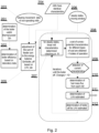
- Fig. 2 shows a flowchart for carrying out the method according to the invention.
- step 201 the boiler useful thermal power (Qin) is determined, which indicates the amount of energy transferred from the boiler 10 to the turbine 41, 42 in the form of steam.
- Qin the boiler useful thermal power
- step 202 the initial efficiency of the boiler is determined on the basis of historical 24-hour - average laboratory data of calorific value and the composition of the fuel, according to the PN-EN 12952-15:2004 standard.
- step 203 processing of measurement data from the environment of the coal mills is carried out so as to remove erroneous indication values generated by currently deactivated mills 13, e.g. the error of negative revolutions of feeders of a non-operating mill 13.
- step 204 it is initially assumed that mill characteristics are identical for all of the mills 13, which corresponds to the assumption that each mill hopper 14 contains a fuel with the same properties.
- step 205 Based on the data from steps 202, 203, 204, in step 205 the fuel mass flow rate is adjusted by selecting appropriate mill characteristics.
- the resulting fuel mass flux is related to the 24-hour-average laboratory calorific value, so that the balance of the amount of chemical energy of the fuel fed to the boiler is fulfilled.
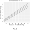
- step 207 for the steady states of boiler operation provided in step 206, linear mill characteristics 1-4 are created as shown in Fig. 3 (determining the dependence of the mass flow [expressed in t/h] on the load of the mill feeder motors (which is translated to coal feeder revolutions) [expressed in %]) based on determination coefficient metric R2.
- a set of mill characteristics is obtained, i.e. individual characteristics for different fuel qualities, which are a measure of the coal's susceptibility to milling, as for example shown in Fig. 3 .
- step 209 the current mill characteristics are detected (individually for each mill) based on the measured operational parameters of the coal mill, such as mill motor power, pressure of air entering the mill, revolutions of mill feeders.
- the mass flow of fuel fed by a particular mill is determined in step 210.
- the characteristic is selected depending on at least one currently measurement parameter of the mill (when the measured parameter is changed, another characteristic is selected).
- step 211 the estimated LHV of the fuel is determined based on the energy balances and the determined boiler efficiency and it is reported as the result of the procedure.
- LHV Q ⁇ in m ⁇ pal ⁇ ⁇ boiler wherein ⁇ pal is the mass flow of fuel
- step 212 the boiler efficiency for the thus estimated LHV is determined according to the PN-EN 12952-15:2004 standard.
- the boiler efficiency is determined on an ongoing basis (on-line) for a particular historical moment, e. g. for every minute. After updating the calorific value, the boiler efficiency is calculated again.
- the LHV estimated in step 211 and the boiler efficiency estimated in step 212 are provided as input to step 207, allowing a more accurate determination of the set of characteristics.
- steps 207-212 are performed iteratively until the boiler efficiency calculation error (i. e. the difference between successive iterations of steps 207-212) converges to a value below a predetermined threshold, for example of the order of 10 -3 .
- the calculation error is defined as
- the process described in Fig. 2 in steps 207-212 is implemented on historical data of the block operation (i.e. data collected over a certain period of time, for example several months or several years) and on laboratory data of fuel properties.
- the historical data and results prepared in this way in particular the estimated LHV, mill characteristics, fuel flow rate and boiler efficiency (after obtaining the error convergence) are used to train and test an artificial intelligence model configured to predict the current calorific value of the fuel.
- Other operational data of the block can be used as well, such as operational parameters of turbine, including flows, pressures and temperatures for live steam, superheated steam and secondary steam, operational data of the boiler, operational data of at least one mill, composition of exhaust gases, power of the block.
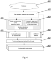
- Fig. 4 shows a simplified diagram of the module for on-line determination of calorific value.
- the data are retrieved from a database 401 (or other type of archive module), both for preparation and on-line operation of the model.
- the data are validated (by removing incorrect indications or by simulating their correct values and processed (e.g. by aggregation or by extracting averages from several measurement sensors) in order to obtain meaningful values for further modules.
- basic operational factors are determined, such as secondary steam flux (if not measured), boiler thermal power Q in , chemical energy of fuel supplied to the boiler q Pal , boiler losses and boiler efficiency.
- operation characteristics for the coal mills (as shown in Fig.
- the calorific value is recalculated for historical data which, in combination with the measurement sensor data retrieved in module 406 (i.e.: live and secondary steam parameters, mill system operational parameters, parameters of air supplied to the boiler, flue gas parameters, operating settings, flue gas denitrification system operational parameters, boiler support equipment operational parameters and atmospheric parameters), are used to train the model based on artificial intelligence algorithms 407 to determine the calorific value.
- the prepared model 408 predicts the current calorific value of the fuel based on the measurement data retrieved in module 406.
- An artificial intelligence model 408 based on recursive elements is used, which allows the effect of energy accumulation and the response delays of automation and control systems to be included in the model.
- the module 408 is trained by means of the module 407 such that the historical operational data of the boiler operation with the corresponding calorific value of the fuel is used for training the artificial intelligence model. Then, such trained model 408 can be used to predict on-line (i. e. on an ongoing basis) the calorific value of the fuel based on current operational data.
- Fig. 5 shows a simplified diagram of the method for determining the calorific value, which is a generalisation of the flowchart in Fig. 2 .
- step 501 the operation characteristics of the mill 13 for different types of coal are determined.
- step 502 current efficiency of the boiler is determined.
- step 503 current operation characteristics of the mill 13 are detected, and in step 504, calorific value of the fuel is determined on an ongoing basis (for example, for each minute).
Landscapes
- Engineering & Computer Science (AREA)
- General Engineering & Computer Science (AREA)
- Chemical & Material Sciences (AREA)
- Physics & Mathematics (AREA)
- Life Sciences & Earth Sciences (AREA)
- Mechanical Engineering (AREA)
- Combustion & Propulsion (AREA)
- General Physics & Mathematics (AREA)
- Health & Medical Sciences (AREA)
- Environmental & Geological Engineering (AREA)
- Theoretical Computer Science (AREA)
- General Health & Medical Sciences (AREA)
- Software Systems (AREA)
- Artificial Intelligence (AREA)
- Molecular Biology (AREA)
- Mathematical Physics (AREA)
- Evolutionary Computation (AREA)
- Data Mining & Analysis (AREA)
- Computational Linguistics (AREA)
- Sustainable Energy (AREA)
- Sustainable Development (AREA)
- Computing Systems (AREA)
- Biomedical Technology (AREA)
- Biophysics (AREA)
- Pathology (AREA)
- Immunology (AREA)
- Biochemistry (AREA)
- Analytical Chemistry (AREA)
- Medicinal Chemistry (AREA)
- Food Science & Technology (AREA)
- Wood Science & Technology (AREA)
- Thermal Sciences (AREA)
- Control Of Steam Boilers And Waste-Gas Boilers (AREA)
- Regulation And Control Of Combustion (AREA)
Applications Claiming Priority (2)
| Application Number | Priority Date | Filing Date | Title |
|---|---|---|---|
| EP21461552 | 2021-06-11 | ||
| PCT/EP2022/065842 WO2022258811A1 (en) | 2021-06-11 | 2022-06-10 | A method and a system for monitoring and on-line determining of a calorific value of solid fuel that is currently combusted in a boiler |
Publications (3)
| Publication Number | Publication Date |
|---|---|
| EP4352339A1 EP4352339A1 (en) | 2024-04-17 |
| EP4352339B1 true EP4352339B1 (en) | 2024-09-04 |
| EP4352339C0 EP4352339C0 (en) | 2024-09-04 |
Family
ID=77910730
Family Applications (1)
| Application Number | Title | Priority Date | Filing Date |
|---|---|---|---|
| EP22732261.7A Active EP4352339B1 (en) | 2021-06-11 | 2022-06-10 | A method and a system for monitoring and on-line determining of a calorific value of solid fuel that is currently combusted in a boiler |
Country Status (4)
| Country | Link |
|---|---|
| US (1) | US20240272016A1 (pl) |
| EP (1) | EP4352339B1 (pl) |
| PL (1) | PL4352339T3 (pl) |
| WO (1) | WO2022258811A1 (pl) |
Families Citing this family (1)
| Publication number | Priority date | Publication date | Assignee | Title |
|---|---|---|---|---|
| CN117606036B (zh) * | 2023-11-22 | 2024-06-04 | 广东宝杰环保科技有限公司 | 固体废物燃烧污染防治设备及其灰渣积聚预测方法 |
Family Cites Families (2)
| Publication number | Priority date | Publication date | Assignee | Title |
|---|---|---|---|---|
| US4969408A (en) * | 1989-11-22 | 1990-11-13 | Westinghouse Electric Corp. | System for optimizing total air flow in coal-fired boilers |
| US20120083933A1 (en) * | 2010-09-30 | 2012-04-05 | General Electric Company | Method and system to predict power plant performance |
-
2022
- 2022-06-10 US US18/568,823 patent/US20240272016A1/en active Pending
- 2022-06-10 WO PCT/EP2022/065842 patent/WO2022258811A1/en not_active Ceased
- 2022-06-10 EP EP22732261.7A patent/EP4352339B1/en active Active
- 2022-06-10 PL PL22732261.7T patent/PL4352339T3/pl unknown
Also Published As
| Publication number | Publication date |
|---|---|
| PL4352339T3 (pl) | 2024-11-04 |
| EP4352339C0 (en) | 2024-09-04 |
| US20240272016A1 (en) | 2024-08-15 |
| EP4352339A1 (en) | 2024-04-17 |
| WO2022258811A1 (en) | 2022-12-15 |
Similar Documents
| Publication | Publication Date | Title |
|---|---|---|
| US8140296B2 (en) | Method and apparatus for generalized performance evaluation of equipment using achievable performance derived from statistics and real-time data | |
| EP2444869B1 (en) | Method and apparatus for generalized performance evaluation of equipment using achievable performance derived from statistics and real-time data | |
| CN112859780B (zh) | 一种基于云数据、云计算的火电厂智慧燃烧控制方法 | |
| CN110458724B (zh) | 一种基于神经网络预测火电机组深度调峰能力的方法 | |
| CN112131517B (zh) | 一种垃圾焚烧电厂入炉垃圾低位热值的测算方法 | |
| CN101561676A (zh) | 火力发电机组部件剩余寿命在线监视与控制装置及方法 | |
| CN112395744B (zh) | 一种面向火电厂的设备安全性在线评价方法及系统 | |
| CN111753389B (zh) | 一种燃煤锅炉入炉原煤热值在线软测量方法和装置 | |
| EP4352339B1 (en) | A method and a system for monitoring and on-line determining of a calorific value of solid fuel that is currently combusted in a boiler | |
| US7398652B1 (en) | System for optimizing a combustion heating process | |
| CN113918881B (zh) | 基于分层多项式模型的飞灰含碳量软测量方法及监测系统 | |
| US6810358B1 (en) | Method to synchronize data when used for input/loss performance monitoring of a power plant | |
| US6230495B1 (en) | Method for optimizing fossil-fueled power stations | |
| Chong et al. | Prediction of gaseous emissions from a chain grate stoker boiler using neural networks of ARX structure | |
| US20130168971A1 (en) | Working fluid sensor system for power generation system | |
| Agbleze et al. | Modeling and control of subcritical coal-fired power plant components for fault detection | |
| EP2644850A1 (en) | A system for analyzing operation of power plant units and a method for analyzing operation of power plant units | |
| CN117421553A (zh) | 一种受热面汽水系统泄漏监测方法 | |
| CN113836794B (zh) | 一种软硬结合的飞灰含碳量在线监测方法 | |
| KR20240081633A (ko) | 발전용 플랜트의 운전장애 예측 방법 | |
| Hartner et al. | Model-based data reconciliation to improve accuracy and reliability of performance evaluation of thermal power plants | |
| CN111503656B (zh) | 一种生活垃圾燃烧发电优化系统、方法及存储介质 | |
| CN118091052B (zh) | 一种基于cems的二氧化碳在线监测方法及系统 | |
| RU2783863C1 (ru) | Способ комплексной оптимизации параметров энергоблока | |
| CN119802657A (zh) | 一种塔式锅炉燃烧效率的实时监测系统 |
Legal Events
| Date | Code | Title | Description |
|---|---|---|---|
| STAA | Information on the status of an ep patent application or granted ep patent |
Free format text: STATUS: UNKNOWN |
|
| STAA | Information on the status of an ep patent application or granted ep patent |
Free format text: STATUS: THE INTERNATIONAL PUBLICATION HAS BEEN MADE |
|
| STAA | Information on the status of an ep patent application or granted ep patent |
Free format text: STATUS: EXAMINATION IS IN PROGRESS |
|
| PUAI | Public reference made under article 153(3) epc to a published international application that has entered the european phase |
Free format text: ORIGINAL CODE: 0009012 |
|
| STAA | Information on the status of an ep patent application or granted ep patent |
Free format text: STATUS: REQUEST FOR EXAMINATION WAS MADE |
|
| GRAP | Despatch of communication of intention to grant a patent |
Free format text: ORIGINAL CODE: EPIDOSNIGR1 |
|
| STAA | Information on the status of an ep patent application or granted ep patent |
Free format text: STATUS: GRANT OF PATENT IS INTENDED |
|
| 17P | Request for examination filed |
Effective date: 20240104 |
|
| AK | Designated contracting states |
Kind code of ref document: A1 Designated state(s): AL AT BE BG CH CY CZ DE DK EE ES FI FR GB GR HR HU IE IS IT LI LT LU LV MC MK MT NL NO PL PT RO RS SE SI SK SM TR |
|
| RIC1 | Information provided on ipc code assigned before grant |
Ipc: G01N 33/22 20060101ALN20240328BHEP Ipc: G06N 3/08 20060101ALN20240328BHEP Ipc: G01K 17/00 20060101ALI20240328BHEP Ipc: F23G 7/10 20060101ALI20240328BHEP Ipc: F23G 5/033 20060101ALI20240328BHEP Ipc: F23D 1/00 20060101ALI20240328BHEP Ipc: F23C 1/12 20060101ALI20240328BHEP Ipc: F22B 35/18 20060101ALI20240328BHEP Ipc: F01K 13/02 20060101AFI20240328BHEP |
|
| DAV | Request for validation of the european patent (deleted) | ||
| DAX | Request for extension of the european patent (deleted) | ||
| INTG | Intention to grant announced |
Effective date: 20240416 |
|
| GRAS | Grant fee paid |
Free format text: ORIGINAL CODE: EPIDOSNIGR3 |
|
| GRAA | (expected) grant |
Free format text: ORIGINAL CODE: 0009210 |
|
| STAA | Information on the status of an ep patent application or granted ep patent |
Free format text: STATUS: THE PATENT HAS BEEN GRANTED |
|
| AK | Designated contracting states |
Kind code of ref document: B1 Designated state(s): AL AT BE BG CH CY CZ DE DK EE ES FI FR GB GR HR HU IE IS IT LI LT LU LV MC MK MT NL NO PL PT RO RS SE SI SK SM TR |
|
| REG | Reference to a national code |
Ref country code: GB Ref legal event code: FG4D |
|
| REG | Reference to a national code |
Ref country code: CH Ref legal event code: EP |
|
| REG | Reference to a national code |
Ref country code: IE Ref legal event code: FG4D |
|
| REG | Reference to a national code |
Ref country code: DE Ref legal event code: R096 Ref document number: 602022005907 Country of ref document: DE |
|
| U01 | Request for unitary effect filed |
Effective date: 20241001 |
|
| U07 | Unitary effect registered |
Designated state(s): AT BE BG DE DK EE FI FR IT LT LU LV MT NL PT RO SE SI Effective date: 20241024 |
|
| PG25 | Lapsed in a contracting state [announced via postgrant information from national office to epo] |
Ref country code: NO Free format text: LAPSE BECAUSE OF FAILURE TO SUBMIT A TRANSLATION OF THE DESCRIPTION OR TO PAY THE FEE WITHIN THE PRESCRIBED TIME-LIMIT Effective date: 20241204 |
|
| PG25 | Lapsed in a contracting state [announced via postgrant information from national office to epo] |
Ref country code: GR Free format text: LAPSE BECAUSE OF FAILURE TO SUBMIT A TRANSLATION OF THE DESCRIPTION OR TO PAY THE FEE WITHIN THE PRESCRIBED TIME-LIMIT Effective date: 20241205 |
|
| PG25 | Lapsed in a contracting state [announced via postgrant information from national office to epo] |
Ref country code: HR Free format text: LAPSE BECAUSE OF FAILURE TO SUBMIT A TRANSLATION OF THE DESCRIPTION OR TO PAY THE FEE WITHIN THE PRESCRIBED TIME-LIMIT Effective date: 20240904 |
|
| PG25 | Lapsed in a contracting state [announced via postgrant information from national office to epo] |
Ref country code: RS Free format text: LAPSE BECAUSE OF FAILURE TO SUBMIT A TRANSLATION OF THE DESCRIPTION OR TO PAY THE FEE WITHIN THE PRESCRIBED TIME-LIMIT Effective date: 20241204 Ref country code: ES Free format text: LAPSE BECAUSE OF FAILURE TO SUBMIT A TRANSLATION OF THE DESCRIPTION OR TO PAY THE FEE WITHIN THE PRESCRIBED TIME-LIMIT Effective date: 20240904 |
|
| PG25 | Lapsed in a contracting state [announced via postgrant information from national office to epo] |
Ref country code: RS Free format text: LAPSE BECAUSE OF FAILURE TO SUBMIT A TRANSLATION OF THE DESCRIPTION OR TO PAY THE FEE WITHIN THE PRESCRIBED TIME-LIMIT Effective date: 20241204 Ref country code: NO Free format text: LAPSE BECAUSE OF FAILURE TO SUBMIT A TRANSLATION OF THE DESCRIPTION OR TO PAY THE FEE WITHIN THE PRESCRIBED TIME-LIMIT Effective date: 20241204 Ref country code: HR Free format text: LAPSE BECAUSE OF FAILURE TO SUBMIT A TRANSLATION OF THE DESCRIPTION OR TO PAY THE FEE WITHIN THE PRESCRIBED TIME-LIMIT Effective date: 20240904 Ref country code: GR Free format text: LAPSE BECAUSE OF FAILURE TO SUBMIT A TRANSLATION OF THE DESCRIPTION OR TO PAY THE FEE WITHIN THE PRESCRIBED TIME-LIMIT Effective date: 20241205 Ref country code: ES Free format text: LAPSE BECAUSE OF FAILURE TO SUBMIT A TRANSLATION OF THE DESCRIPTION OR TO PAY THE FEE WITHIN THE PRESCRIBED TIME-LIMIT Effective date: 20240904 |
|
| PG25 | Lapsed in a contracting state [announced via postgrant information from national office to epo] |
Ref country code: IS Free format text: LAPSE BECAUSE OF FAILURE TO SUBMIT A TRANSLATION OF THE DESCRIPTION OR TO PAY THE FEE WITHIN THE PRESCRIBED TIME-LIMIT Effective date: 20250104 |
|
| PG25 | Lapsed in a contracting state [announced via postgrant information from national office to epo] |
Ref country code: SM Free format text: LAPSE BECAUSE OF FAILURE TO SUBMIT A TRANSLATION OF THE DESCRIPTION OR TO PAY THE FEE WITHIN THE PRESCRIBED TIME-LIMIT Effective date: 20240904 |
|
| PG25 | Lapsed in a contracting state [announced via postgrant information from national office to epo] |
Ref country code: SK Free format text: LAPSE BECAUSE OF FAILURE TO SUBMIT A TRANSLATION OF THE DESCRIPTION OR TO PAY THE FEE WITHIN THE PRESCRIBED TIME-LIMIT Effective date: 20240904 |
|
| PGFP | Annual fee paid to national office [announced via postgrant information from national office to epo] |
Ref country code: PL Payment date: 20250414 Year of fee payment: 4 |
|
| PLBE | No opposition filed within time limit |
Free format text: ORIGINAL CODE: 0009261 |
|
| STAA | Information on the status of an ep patent application or granted ep patent |
Free format text: STATUS: NO OPPOSITION FILED WITHIN TIME LIMIT |
|
| PGFP | Annual fee paid to national office [announced via postgrant information from national office to epo] |
Ref country code: TR Payment date: 20250526 Year of fee payment: 4 |
|
| PGFP | Annual fee paid to national office [announced via postgrant information from national office to epo] |
Ref country code: CZ Payment date: 20250523 Year of fee payment: 4 |
|
| U20 | Renewal fee for the european patent with unitary effect paid |
Year of fee payment: 4 Effective date: 20250628 |
|
| 26N | No opposition filed |
Effective date: 20250605 |