EP4351911B1 - Fuel tank venting system - Google Patents
Fuel tank venting system Download PDFInfo
- Publication number
- EP4351911B1 EP4351911B1 EP22732154.4A EP22732154A EP4351911B1 EP 4351911 B1 EP4351911 B1 EP 4351911B1 EP 22732154 A EP22732154 A EP 22732154A EP 4351911 B1 EP4351911 B1 EP 4351911B1
- Authority
- EP
- European Patent Office
- Prior art keywords
- fuel tank
- fuel
- venting system
- venting
- vapor
- Prior art date
- Legal status (The legal status is an assumption and is not a legal conclusion. Google has not performed a legal analysis and makes no representation as to the accuracy of the status listed.)
- Active
Links
Images


Classifications
-
- B—PERFORMING OPERATIONS; TRANSPORTING
- B60—VEHICLES IN GENERAL
- B60K—ARRANGEMENT OR MOUNTING OF PROPULSION UNITS OR OF TRANSMISSIONS IN VEHICLES; ARRANGEMENT OR MOUNTING OF PLURAL DIVERSE PRIME-MOVERS IN VEHICLES; AUXILIARY DRIVES FOR VEHICLES; INSTRUMENTATION OR DASHBOARDS FOR VEHICLES; ARRANGEMENTS IN CONNECTION WITH COOLING, AIR INTAKE, GAS EXHAUST OR FUEL SUPPLY OF PROPULSION UNITS IN VEHICLES
- B60K15/00—Arrangement in connection with fuel supply of combustion engines or other fuel consuming energy converters, e.g. fuel cells; Mounting or construction of fuel tanks
- B60K15/03—Fuel tanks
- B60K15/035—Fuel tanks characterised by venting means
-
- B—PERFORMING OPERATIONS; TRANSPORTING
- B60—VEHICLES IN GENERAL
- B60K—ARRANGEMENT OR MOUNTING OF PROPULSION UNITS OR OF TRANSMISSIONS IN VEHICLES; ARRANGEMENT OR MOUNTING OF PLURAL DIVERSE PRIME-MOVERS IN VEHICLES; AUXILIARY DRIVES FOR VEHICLES; INSTRUMENTATION OR DASHBOARDS FOR VEHICLES; ARRANGEMENTS IN CONNECTION WITH COOLING, AIR INTAKE, GAS EXHAUST OR FUEL SUPPLY OF PROPULSION UNITS IN VEHICLES
- B60K15/00—Arrangement in connection with fuel supply of combustion engines or other fuel consuming energy converters, e.g. fuel cells; Mounting or construction of fuel tanks
- B60K15/03—Fuel tanks
- B60K15/035—Fuel tanks characterised by venting means
- B60K15/03504—Fuel tanks characterised by venting means adapted to avoid loss of fuel or fuel vapour, e.g. with vapour recovery systems
- B60K2015/03514—Fuel tanks characterised by venting means adapted to avoid loss of fuel or fuel vapour, e.g. with vapour recovery systems with vapor recovery means
-
- B—PERFORMING OPERATIONS; TRANSPORTING
- B60—VEHICLES IN GENERAL
- B60K—ARRANGEMENT OR MOUNTING OF PROPULSION UNITS OR OF TRANSMISSIONS IN VEHICLES; ARRANGEMENT OR MOUNTING OF PLURAL DIVERSE PRIME-MOVERS IN VEHICLES; AUXILIARY DRIVES FOR VEHICLES; INSTRUMENTATION OR DASHBOARDS FOR VEHICLES; ARRANGEMENTS IN CONNECTION WITH COOLING, AIR INTAKE, GAS EXHAUST OR FUEL SUPPLY OF PROPULSION UNITS IN VEHICLES
- B60K15/00—Arrangement in connection with fuel supply of combustion engines or other fuel consuming energy converters, e.g. fuel cells; Mounting or construction of fuel tanks
- B60K15/03—Fuel tanks
- B60K15/035—Fuel tanks characterised by venting means
- B60K2015/03561—Venting means working at specific times
-
- B—PERFORMING OPERATIONS; TRANSPORTING
- B60—VEHICLES IN GENERAL
- B60K—ARRANGEMENT OR MOUNTING OF PROPULSION UNITS OR OF TRANSMISSIONS IN VEHICLES; ARRANGEMENT OR MOUNTING OF PLURAL DIVERSE PRIME-MOVERS IN VEHICLES; AUXILIARY DRIVES FOR VEHICLES; INSTRUMENTATION OR DASHBOARDS FOR VEHICLES; ARRANGEMENTS IN CONNECTION WITH COOLING, AIR INTAKE, GAS EXHAUST OR FUEL SUPPLY OF PROPULSION UNITS IN VEHICLES
- B60K15/00—Arrangement in connection with fuel supply of combustion engines or other fuel consuming energy converters, e.g. fuel cells; Mounting or construction of fuel tanks
- B60K15/03—Fuel tanks
- B60K15/035—Fuel tanks characterised by venting means
- B60K2015/03561—Venting means working at specific times
- B60K2015/03576—Venting during filling the reservoir
Definitions
- the invention relates to a fuel tank venting system for an automotive vehicle and an automotive vehicle comprising such a system. More precisely, the invention relates to on board refueling vapor recovery systems on automotive vehicle, especially on hybrid automotive vehicle.
- Such type of fuel vapor recovery system has a fuel vapor trap, or canister, that captures fuel vapors, a refueling valve and one or more vent valves that are located at the top of the fuel tank for handling the fuel vapors in the fuel tank.
- US 2020/0198462 A1 discloses a valve module for an operating fluid container system
- GB 2 588 778 A discloses a vapor canister for a vehicular evaporative emissions control system
- US 2018/0087475 A1 discloses a fuel tank system including an evaporative emissions control system
- US 2016/0298576 A1 discloses a fuel tank evaporative emissions control and diagnostic system.
- a Roll-Over Valve (ROV) is used to close the fuel system in case of a roll over event due to an accident of the vehicle; a fill limit vent valve (FLVV) is used to prevent overfilling of the tank.
- ROV Roll-Over Valve
- FLVV fill limit vent valve
- the use of these valves makes the fuel tank system very expensive and complicated to produce.
- the valves take a lot of place in the fuel system, especially inside the fuel tank, which means that the capacity of the tank can be unsatisfactory.
- the object of the invention is to overcome the disadvantages of the known venting system by providing a fuel tank venting system that is cheaper, simpler and space saving especially inside the fuel tank.
- the present invention thus provides a fuel tank venting system for an automotive vehicle comprising:
- a pressure relief valve is located between the normally closed shutter device and the fuel vapor trap, said valve being positioned in parallel with the normally closed shutter device.
- the entire fuel system is thus closed after refueling and during normal operation of the vehicle which contributes to the increase of the pressure in the fuel tank under the closed environment. It is known that the volatility of the fuel decreases when the pressure in the fuel tank increases. As a result, in a closed fuel tank system, no fuel vapor goes into the fuel vapor trap and nothing will be loaded on the fuel vapor trap.
- the fuel tank venting system is particularly advantageous on a hybrid automotive vehicle to reduce CO 2 emission.
- a hybrid automotive vehicle operates either by using only the electric motor, or only the engine, or both of them together, depending on the vehicle model.
- One particular principle of operation is as follows:
- the claimed fuel tank venting system allows a closed fuel tank system which helps to increase the pressure in the fuel tank and thus reduces the fuel vapor trap load, allowing to reduce CO 2 emission.
- valves such as ROV, OPV (Over Pressure Valve) or FLW that are usually present in the prior art, are replaced by the at least one orifice in the claimed fuel tank venting system which frees more room for fuel.
- ROV Open Pressure Valve
- OPV Over Pressure Valve
- FLW Flexible Wire
- the removal of the precited valves makes the fuel tank venting system simpler and cheaper.
- the claimed at least one orifice, or vent can be implemented by a simple connection between the fuel tank and the inlet conduit, such as a venting nipple which allows the passage of a liquid and a gas.
- a venting nipple which allows the passage of a liquid and a gas.
- the at least one orifice is configured to be not permanently submerged.
- the inlet conduit is configured to maintain a permanent vapor communication between the fuel vapor trap and the fuel tank in a static condition.
- Static condition means that the vehicle is not moving and not refueling.
- the normally closed shutter device is open only during a vehicle refueling process or when the pressure in the fuel tank reaches a predetermined pressure level.
- the fuel tank venting system allows a closed fuel tank system which helps to increase the pressure in the fuel tank and thus reduces the fuel vapor trap load, allowing to reduce CO 2 emission, while avoiding a pressure in the fuel tank which exceeds the resistance of the fuel tank and may damage the fuel tank, i.e. while guaranteeing tank safety and avoiding its internal pressure becoming too extreme.
- the predetermined pressure level is thus predetermined as a pressure level when the vehicle is not in normal operation.
- the electrically-actuated valve is open only during a vehicle refueling process.
- an active actuation of the normally closed shutter device, wherein the electrically-actuated valve is energized is performed only during a vehicle refueling process.
- the normally closed shutter device comprises one single electrically-actuated valve.
- the fuel tank venting system comprises at least two orifices both connected to the inlet conduit by a venting pipe outside the fuel tank, the orifices being preferably arranged in different areas on the top wall of the fuel tank.
- the inclination of the vehicle may lead the liquid level to one or several orifices in such a way that the orifices in question are immerged in the fuel.
- Orifices being arranged in different areas on the top wall of the fuel tank can make sure that at least one or some orifices still work when the fuel tank is inclined which permits to assure a permanent vapor communication between the fuel vapor dome and the fuel vapor trap.
- the venting pipe is outside the fuel tank, there is more space inside the fuel tank.
- the assembly of the venting pipe with the tank is quite simple. Moreover, the cost of the fuel tank venting system can be reduced.
- the fuel tank venting system comprises a venting pipe inside the fuel tank, the venting pipe being connected to the orifice and presenting at least one secondary orifice that is permanently open allowing a communication between the fuel tank and the inlet conduit.
- an alternative solution is provided to resolve immersion risk of some orifices in case of inclination of the fuel tank which is not limited by any permeability requirement of the fuel vapor.
- the venting pipe is inside the tank, the assembly of the fuel tank venting system on the vehicle is simplified and less permeation of the fuel vapor is occurred.
- the inlet of the venting pipe for fuel vapor should advantageously be arranged in the vapor dome.
- the inlet orifice should be arranged above the maximum liquid level in the fuel tank, which means in the fuel tank vapor dome.
- the fuel tank venting system comprises a liquid vapor separator in the inlet conduit, the liquid vapor separator being arranged between the fuel vapor trap and the orifice, preferably above the maximum fuel level in the fuel tank.
- the liquid vapor separator is preferably above the liquid level in the fuel tank, even on an inclined slope. To this end, it is preferable to place the liquid vapor separator as high as possible.
- the liquid vapor separator comprises at least one roll-over valve arranged in and above the maximum fuel level of the liquid vapor separator.
- the roll-over valve is configured to shut down the communication between the fuel tank and the fuel vapor trap in case of line breakage or a Roll Over Event. With the ROV, the fuel is kept inside the fuel system and cannot be released to the atmosphere.
- a high flow roll-over valve which is able to accommodate the vapor flow in all conditions, such as refueling condition or some specific driving conditions with different temperatures and atmospheric pressures.
- the fuel vapor trap is placed in a venting zone that is configured in accordance with the geometry of the fuel tank in such a manner the fuel vapor trap always stays away from the fuel when the vehicle is inclined in any direction and of at least 12%, preferably up to 15% and even preferably up to 30%.
- the fuel vapor trap is placed high enough above the fuel tank when the vehicle is on a flat surface.
- the fuel vapor trap should have a gap with the fuel tank in a transversal direction to avoid being immerged when the fuel tank is inclined in any direction.
- the fuel tank venting system comprises a recirculation line connecting the liquid vapor separator and a head of the refueling pipe to decrease the vapor generation in the tank and to reduce the fuel vapor trap load, allowing to reduce CO 2 emission.
- the fuel tank venting system comprises a level sensor inside the fuel tank capable of sending a signal when the fuel reaches a predetermined level, the signal being related to the shutdown of the normally closed shutter device.
- the signal of level detecting can trigger the shutdown of the normally closed shutter device immediately or with a time delay. No other electronical device is need for controlling this action which is cost saving.
- the system can work without any level sensor and the normally closed shutter device is time-controlled, the timer being calculated by fuel tank volume and the rate of the refueling.
- the normally closed shutter device comprises a pair of valves comprising an over-pressure relief (OPR) valve and an under-pressure relief (UPR) valve or a combined pressure / vacuum relief valve (P/VRV) for guaranteeing tank safety and avoiding its internal pressure becoming too extreme.
- OPR over-pressure relief
- URR under-pressure relief
- P/VRV combined pressure / vacuum relief valve
- the present invention provides also an automotive vehicle comprising a fuel tank venting system as described above.
- FIGS.1 to 7 show certain preferred variants.
- a fuel tank venting system 10 for an automotive vehicle in accordance with a first embodiment of the invention includes a fuel tank 1, a refueling pipe 2 that is closed by a fuel cap, a fuel vapor trap 3, for example a canister containing activated charcoal, carbon, or other material that absorbs and desorbs fuel vapors.
- the fuel vapor trap 3 thus receives and stores fuel vapors from the fuel tank 1 and then delivers these stored fuel vapors to a fuel charge device for combustion in the vehicle engine.
- the fuel vapor trap 3 is connected to the fuel tank 1 by an inlet conduit 4.
- the inlet conduit 4 is connected with the fuel tank 1 only through one orifice 5 which is permanently open when the vehicle is in static condition.
- the inlet conduit 4 is configured to maintain a permanent vapor communication between the fuel vapor trap 3 and the fuel tank 1 in a static condition.
- the orifice 5 is arranged in a top wall 11 of the fuel tank 1 so that the orifice 5 is not permanently submerged in the liquid.
- the orifice 5 is carried by a venting connection capable of connecting the inlet conduit 4 to the fuel tank 1.
- the venting connection can be a venting nipple fixed on a tank wall.
- the fuel vapor trap 3 is connected to a normally closed shutter device 6 configured to communicate with the atmosphere.
- the normally closed shutter device 6 is connected to the fuel vapor trap 3 by an outlet conduit 7.
- the normally closed shutter device 6 comprises an electrically-actuated valve, in particular one single electrically-actuated valve, for example a solenoid valve, being closed when the electrically-actuated valve is de-energized.
- the normally closed shutter device 6 is configured to be open during vehicle refueling process and to be closed when the fuel in the fuel tank 1 reaches a predetermined fill level and when the vehicle is in normal operation. In other words, the normally closed shutter device 6 is open only during vehicle refueling process.
- the normally closed shutter device 6 is open only in the following cases: a first case, during vehicle refueling process, and a second case, when the pressure in the fuel tank 1 reaches a predetermined pressure level.
- a predetermined pressure level is for example an over-pressure or an under-pressure compared to the ambient pressure, which is for example determined relatively to the pressure resistance of the fuel tank 1.
- An over-pressure is for example selected between 0,3 bar and 1 bar above the ambient pressure, and may occur for example in summer when the vehicle is stopped for a long time in a sunny area.
- An under-pressure is for example selected between -0,1 bar and -0,3 bar below the ambient pressure.
- the normally closed shutter device 6 comprises a passive valve, for example a mechanically-actuated valve, which is opened passively when the predetermined pressure level is reached, i.e. which opens under the effect of the pressure difference between the ambient pressure and the pressure in the fuel tank, and which is otherwise closed passively, i.e. when the predetermined pressure level is not reached or no more reached.
- a passive valve for example a mechanically-actuated valve, which is opened passively when the predetermined pressure level is reached, i.e. which opens under the effect of the pressure difference between the ambient pressure and the pressure in the fuel tank, and which is otherwise closed passively, i.e. when the predetermined pressure level is not reached or no more reached.
- the electrically-actuated valve and the passive valve are arranged in parallel, each connecting the outlet conduit 7 to the atmosphere, when opened.
- the normally closed shutter device comprises a pair of valves comprising an over-pressure relief (OPR) valve and an under-pressure relief (UPR) valve or a combined pressure / vacuum relief valve (P/VRV) for guaranteeing tank safety and avoiding its internal pressure becoming too extreme.
- OCR over-pressure relief
- URR under-pressure relief
- P/VRV combined pressure / vacuum relief valve
- the fuel tank venting system can comprise a level sensor inside the fuel tank 1 capable of sending a signal when the fuel reaches a predetermined level, the signal being related to the shutdown of the normally closed shutter device 6.
- the fuel tank venting system comprises a liquid vapor separator (LVS) 8 in the inlet conduit 4, the liquid vapor separator 8 being arranged between the fuel vapor trap 3 and the orifice 5.
- the liquid vapor separator 8 is arranged above the maximum fuel level in the fuel tank 1.
- LVS LVS
- Passive for example known from Patent EP 1 020 670 in the name of the Applicant, which comprise in their base a simple valve that opens under the effect of the weight of liquid that they contain
- active for example known from U.S. Pat. No. 6,698,475 , which are drained by means of an active device (a pump, for example a jet pump).
- the fuel tank venting system comprises a roll-over valve 9 that is arranged in the liquid vapor separator 8.
- the roll-over valve 9 performs a function of closing the fuel tank 1 automatically as soon as the latter begins to be overturned.
- the roll-over valve comprises a high-density ball device resting in a cage, the bottom of which has a conical shape so that when the ball is displaced, it pushes upwards a valve capable of shutting off the inlet conduit 4 leading to the fuel vapor trap 3.
- the roll-over valve 9 is arrange above the maximum fuel level of the liquid vapor separator 8.
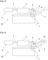
- FIG.4 illustrates a fourth embodiment of the invention in which a recirculation line 12 is used to connect the liquid vapor separator 8 and a head of the refueling pipe 2 to decrease the vapor generation in the fuel tank 1.
- FIG.5 illustrates a fifth embodiment of the invention which is an improvement of the fourth embodiment for use of large and/or complex fuel tank.
- the fuel tank 1 comprises a second orifice 5'.
- the two orifices 5, 5' are arranged in different areas on the top wall 11 of the fuel tank 1 and both orifices 5, 5' are connected to the inlet conduit 4 by a venting pipe 13.
- the venting pipe 13 communicating with the orifices 5, 5' and the LVS 8 is arranged outside the fuel tank 1.
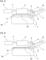
- FIG.6 An alternative of the fifth embodiment is illustrated by FIG.6 wherein the fuel tank venting system comprises a venting pipe 13' inside the fuel tank 1.
- the venting pipe 13' is connected to an orifice 5 arrange on the top wall 11 of the fuel tank 1.
- the venting pipe 13' comprises one secondary orifice 51 that is permanently open.
- both of the orifice 5 and the secondary orifice 51 communicate with the inlet conduit 4 through the venting pipe 13'.
- the fuel vapor trap 3 is placed in a venting zone that is configured in accordance with the geometry of the fuel tank 1 in such a manner the fuel vapor trap 3 always stays away from the fuel when the vehicle is inclined in any direction and of at least 12%, preferably up to 15% and even preferably up to 30%.
- the LVS 8 is place higher than the liquid level in the fuel tank 1.
- the inlet conduit 4 can be arranged inside the fuel tank and in contact with the liquid.
- the LVS 8 and the fuel vapor trap 6 can be arranged below the fuel tank 1 and lower to the liquid level.
- the inlet conduit 4 may have a U shape as shown in FIG.8 , the inlet conduit having a shape with an elevation point configured to impeach the liquid fuel to go in the fuel trap. In this manner, no liquid will be able to enter the fuel vapor trap 6 which avoids contamination of the fuel vapor trap 6 with fuel liquid.
Landscapes
- Engineering & Computer Science (AREA)
- Life Sciences & Earth Sciences (AREA)
- Sustainable Development (AREA)
- Sustainable Energy (AREA)
- Chemical & Material Sciences (AREA)
- Combustion & Propulsion (AREA)
- Transportation (AREA)
- Mechanical Engineering (AREA)
- Cooling, Air Intake And Gas Exhaust, And Fuel Tank Arrangements In Propulsion Units (AREA)
- Safety Valves (AREA)
Description
- The invention relates to a fuel tank venting system for an automotive vehicle and an automotive vehicle comprising such a system. More precisely, the invention relates to on board refueling vapor recovery systems on automotive vehicle, especially on hybrid automotive vehicle.
- Such type of fuel vapor recovery system has a fuel vapor trap, or canister, that captures fuel vapors, a refueling valve and one or more vent valves that are located at the top of the fuel tank for handling the fuel vapors in the fuel tank.
- Among prior art documents,
US 2020/0198462 A1 discloses a valve module for an operating fluid container system,GB 2 588 778 AUS 2018/0087475 A1 discloses a fuel tank system including an evaporative emissions control system, andUS 2016/0298576 A1 discloses a fuel tank evaporative emissions control and diagnostic system. - For example, a Roll-Over Valve (ROV) is used to close the fuel system in case of a roll over event due to an accident of the vehicle; a fill limit vent valve (FLVV) is used to prevent overfilling of the tank. However, the use of these valves makes the fuel tank system very expensive and complicated to produce. In addition, the valves take a lot of place in the fuel system, especially inside the fuel tank, which means that the capacity of the tank can be unsatisfactory.
- The object of the invention is to overcome the disadvantages of the known venting system by providing a fuel tank venting system that is cheaper, simpler and space saving especially inside the fuel tank.
- The present invention thus provides a fuel tank venting system for an automotive vehicle comprising:
- a fuel tank comprising a vapor dome,
- a refueling pipe,
- a fuel vapor trap that is connected to the fuel tank by an inlet conduit, wherein the inlet conduit is connected with the fuel tank through at least one orifice which is permanently open, the orifice being arranged in the vapor dome of the fuel tank in a static condition, the orifice being preferably arranged in a wall of the fuel tank, more preferably arranged in a top wall of the fuel tank.
- a normally closed shutter device that communicates with the atmosphere and that is connected to the fuel vapor trap by an outlet conduit, the normally closed shutter device comprising an electrically-actuated valve being closed when the electrically-actuated valve is de-energized,
- Preferably, a pressure relief valve is located between the normally closed shutter device and the fuel vapor trap, said valve being positioned in parallel with the normally closed shutter device.
- The entire fuel system is thus closed after refueling and during normal operation of the vehicle which contributes to the increase of the pressure in the fuel tank under the closed environment. It is known that the volatility of the fuel decreases when the pressure in the fuel tank increases. As a result, in a closed fuel tank system, no fuel vapor goes into the fuel vapor trap and nothing will be loaded on the fuel vapor trap.
- The fuel tank venting system is particularly advantageous on a hybrid automotive vehicle to reduce CO2 emission. Indeed, a hybrid automotive vehicle operates either by using only the electric motor, or only the engine, or both of them together, depending on the vehicle model. One particular principle of operation is as follows:
- during static condition (when the vehicle is not moving), the engine and the electric motor are both stopped;
- on starting, it is the electric motor that causes the car to move, up to higher speeds;
- when higher speeds are reached, the combustion engine takes over;
- in the event of hard acceleration, both the combustion engine and the electric motor are observed to operate simultaneously, thus making it possible to achieve acceleration equivalent to that of an engine having the same power, or even greater acceleration;
- during a stage of deceleration and braking, kinetic energy is eventually used for recharging the batteries, depending on the vehicle model.
- Indeed, during a fuel vapor trap purge, vapors are sucked from the fuel vapor trap by engine air intake vacuum which occurs at low engine load. Thus, the combustion engine runs in a non-efficient operation mode; when the engine is completed with an electric motor, the aim is to avoid running the engine in non-efficient operation mode. Actually, during a Worldwide harmonized Light vehicles Test Cycles (WLTC) for example, it was found that when the hybrid engines do not operate in low load (non-efficient) mode, more fuel can be saved and CO2 emissions are reduced; some plug-in hybrid vehicles do entirely switch off the combustion engine whenever possible in order to run purely in EV (electric vehicle) mode and without any CO2 emission. In the latter specific case, it is important to avoid a fully loaded fuel vapor trap because it will need a purge by the engine and then in such a case, the engine would have to be switched on only for fuel vapor trap purging, which leads to unnecessary CO2 emission.
- In view of the above, the claimed fuel tank venting system allows a closed fuel tank system which helps to increase the pressure in the fuel tank and thus reduces the fuel vapor trap load, allowing to reduce CO2 emission.
- Moreover, on one hand, the valves such as ROV, OPV (Over Pressure Valve) or FLW that are usually present in the prior art, are replaced by the at least one orifice in the claimed fuel tank venting system which frees more room for fuel. Thus, the capacity of the fuel tank is improved. On the other hand, the removal of the precited valves makes the fuel tank venting system simpler and cheaper.
- We understand that the claimed at least one orifice, or vent, can be implemented by a simple connection between the fuel tank and the inlet conduit, such as a venting nipple which allows the passage of a liquid and a gas. There is no moving part arranged in the orifice for controlling the communication between the fuel tank and the inlet conduit. Preferably, there is no moving part in the wall of the fuel tank. It is to be understood that the at least one orifice is configured to be not permanently submerged.
- It is also understood that the inlet conduit is configured to maintain a permanent vapor communication between the fuel vapor trap and the fuel tank in a static condition. Static condition means that the vehicle is not moving and not refueling.
- An optional feature of the invention is that the normally closed shutter device is open only during a vehicle refueling process or when the pressure in the fuel tank reaches a predetermined pressure level. Thus, the fuel tank venting system allows a closed fuel tank system which helps to increase the pressure in the fuel tank and thus reduces the fuel vapor trap load, allowing to reduce CO2 emission, while avoiding a pressure in the fuel tank which exceeds the resistance of the fuel tank and may damage the fuel tank, i.e. while guaranteeing tank safety and avoiding its internal pressure becoming too extreme. The predetermined pressure level is thus predetermined as a pressure level when the vehicle is not in normal operation.
- Another optional feature of the invention is that the electrically-actuated valve is open only during a vehicle refueling process. Thus, an active actuation of the normally closed shutter device, wherein the electrically-actuated valve is energized, is performed only during a vehicle refueling process.
- Another optional feature of the invention is that the normally closed shutter device comprises one single electrically-actuated valve. Thus, the fuel tank venting system is cheaper and simpler, especially due to the fact that the control of the fuel tank venting system is simplified.
- Another optional feature of the invention is that the fuel tank venting system comprises at least two orifices both connected to the inlet conduit by a venting pipe outside the fuel tank, the orifices being preferably arranged in different areas on the top wall of the fuel tank.
- Thus, in case of large and/or complex tank, the inclination of the vehicle may lead the liquid level to one or several orifices in such a way that the orifices in question are immerged in the fuel. Orifices being arranged in different areas on the top wall of the fuel tank can make sure that at least one or some orifices still work when the fuel tank is inclined which permits to assure a permanent vapor communication between the fuel vapor dome and the fuel vapor trap. As the venting pipe is outside the fuel tank, there is more space inside the fuel tank. In addition, the assembly of the venting pipe with the tank is quite simple. Moreover, the cost of the fuel tank venting system can be reduced.
- Another optional feature of the invention is that the fuel tank venting system comprises a venting pipe inside the fuel tank, the venting pipe being connected to the orifice and presenting at least one secondary orifice that is permanently open allowing a communication between the fuel tank and the inlet conduit.
- Thus, an alternative solution is provided to resolve immersion risk of some orifices in case of inclination of the fuel tank which is not limited by any permeability requirement of the fuel vapor. As the venting pipe is inside the tank, the assembly of the fuel tank venting system on the vehicle is simplified and less permeation of the fuel vapor is occurred.
- It can be understood that the inlet of the venting pipe for fuel vapor should advantageously be arranged in the vapor dome. Thus, when the venting pipe is inside the fuel tank and at least partially in contact with the liquid, the inlet orifice should be arranged above the maximum liquid level in the fuel tank, which means in the fuel tank vapor dome.
- Still another optional feature of the invention is that the fuel tank venting system comprises a liquid vapor separator in the inlet conduit, the liquid vapor separator being arranged between the fuel vapor trap and the orifice, preferably above the maximum fuel level in the fuel tank. The liquid vapor separator is preferably above the liquid level in the fuel tank, even on an inclined slope. To this end, it is preferable to place the liquid vapor separator as high as possible.
- In a preferred embodiment, the liquid vapor separator comprises at least one roll-over valve arranged in and above the maximum fuel level of the liquid vapor separator. The roll-over valve (ROV) is configured to shut down the communication between the fuel tank and the fuel vapor trap in case of line breakage or a Roll Over Event. With the ROV, the fuel is kept inside the fuel system and cannot be released to the atmosphere.
- It is preferable to use a high flow roll-over valve which is able to accommodate the vapor flow in all conditions, such as refueling condition or some specific driving conditions with different temperatures and atmospheric pressures.
- In a further preferred embodiment, the fuel vapor trap is placed in a venting zone that is configured in accordance with the geometry of the fuel tank in such a manner the fuel vapor trap always stays away from the fuel when the vehicle is inclined in any direction and of at least 12%, preferably up to 15% and even preferably up to 30%. For example, the fuel vapor trap is placed high enough above the fuel tank when the vehicle is on a flat surface. Also, the fuel vapor trap should have a gap with the fuel tank in a transversal direction to avoid being immerged when the fuel tank is inclined in any direction.
- Another optional feature of the invention is that the fuel tank venting system comprises a recirculation line connecting the liquid vapor separator and a head of the refueling pipe to decrease the vapor generation in the tank and to reduce the fuel vapor trap load, allowing to reduce CO2 emission.
- Still another optional feature of the invention is that the fuel tank venting system comprises a level sensor inside the fuel tank capable of sending a signal when the fuel reaches a predetermined level, the signal being related to the shutdown of the normally closed shutter device.
- The signal of level detecting can trigger the shutdown of the normally closed shutter device immediately or with a time delay. No other electronical device is need for controlling this action which is cost saving.
- Alternatively, the system can work without any level sensor and the normally closed shutter device is time-controlled, the timer being calculated by fuel tank volume and the rate of the refueling.
- Still another feature of the invention is that the normally closed shutter device comprises a pair of valves comprising an over-pressure relief (OPR) valve and an under-pressure relief (UPR) valve or a combined pressure / vacuum relief valve (P/VRV) for guaranteeing tank safety and avoiding its internal pressure becoming too extreme.
- The present invention provides also an automotive vehicle comprising a fuel tank venting system as described above.
- The present invention is illustrated in non-limiting manner by accompany
FIGS.1 to 7 which show certain preferred variants. - [
Fig. 1] FIG.1 is a schematic drawing of a fuel tank venting system in accordance with a first embodiment of the invention; - [
Fig. 2] FIG.2 is a schematic drawing of a fuel tank venting system in accordance with a second embodiment of the invention; - [
Fig. 3] FIG.3 is a schematic drawing of a fuel tank venting system in accordance with a third embodiment of the invention; - [
Fig. 4] FIG.4 is a schematic drawing of a fuel tank venting system in accordance with a forth embodiment of the invention; - [
Fig. 5] FIG.5 is a schematic drawing of a fuel tank venting system in accordance with a fifth embodiment of the invention; - [
Fig. 6] FIG.6 is a schematic drawing of a fuel tank venting system in accordance with a sixth embodiment of the invention; - [
Fig. 7] FIG.7 is a schematic drawing of a fuel tank venting system in accordance with a seventh embodiment of the invention; - [
Fig.8] FIG.8 is a schematic drawing of a fuel tank venting system in accordance with a eighth embodiment of the invention. - Referring to
FIG.1 , a fueltank venting system 10 for an automotive vehicle in accordance with a first embodiment of the invention includes afuel tank 1, arefueling pipe 2 that is closed by a fuel cap, afuel vapor trap 3, for example a canister containing activated charcoal, carbon, or other material that absorbs and desorbs fuel vapors. Thefuel vapor trap 3 thus receives and stores fuel vapors from thefuel tank 1 and then delivers these stored fuel vapors to a fuel charge device for combustion in the vehicle engine. Thefuel vapor trap 3 is connected to thefuel tank 1 by aninlet conduit 4. - In this embodiment, the
inlet conduit 4 is connected with thefuel tank 1 only through oneorifice 5 which is permanently open when the vehicle is in static condition. Thus, theinlet conduit 4 is configured to maintain a permanent vapor communication between thefuel vapor trap 3 and thefuel tank 1 in a static condition. Theorifice 5 is arranged in atop wall 11 of thefuel tank 1 so that theorifice 5 is not permanently submerged in the liquid. Preferably, theorifice 5 is carried by a venting connection capable of connecting theinlet conduit 4 to thefuel tank 1. For example, the venting connection can be a venting nipple fixed on a tank wall. - In addition, the
fuel vapor trap 3 is connected to a normally closedshutter device 6 configured to communicate with the atmosphere. The normally closedshutter device 6 is connected to thefuel vapor trap 3 by anoutlet conduit 7. The normally closedshutter device 6 comprises an electrically-actuated valve, in particular one single electrically-actuated valve, for example a solenoid valve, being closed when the electrically-actuated valve is de-energized. The normally closedshutter device 6 is configured to be open during vehicle refueling process and to be closed when the fuel in thefuel tank 1 reaches a predetermined fill level and when the vehicle is in normal operation. In other words, the normally closedshutter device 6 is open only during vehicle refueling process. Alternatively, the normally closedshutter device 6 is open only in the following cases: a first case, during vehicle refueling process, and a second case, when the pressure in thefuel tank 1 reaches a predetermined pressure level. In the second case, the vehicle is not in normal operation. Such a predetermined pressure level is for example an over-pressure or an under-pressure compared to the ambient pressure, which is for example determined relatively to the pressure resistance of thefuel tank 1. An over-pressure is for example selected between 0,3 bar and 1 bar above the ambient pressure, and may occur for example in summer when the vehicle is stopped for a long time in a sunny area. An under-pressure is for example selected between -0,1 bar and -0,3 bar below the ambient pressure. In order to open the normally closedshutter device 6 in the second case, i.e. when the pressure in thefuel tank 1 reaches a predetermined pressure level, the normally closedshutter device 6 comprises a passive valve, for example a mechanically-actuated valve, which is opened passively when the predetermined pressure level is reached, i.e. which opens under the effect of the pressure difference between the ambient pressure and the pressure in the fuel tank, and which is otherwise closed passively, i.e. when the predetermined pressure level is not reached or no more reached. For example, the electrically-actuated valve and the passive valve are arranged in parallel, each connecting theoutlet conduit 7 to the atmosphere, when opened. For example, as a passive valve, the normally closed shutter device comprises a pair of valves comprising an over-pressure relief (OPR) valve and an under-pressure relief (UPR) valve or a combined pressure / vacuum relief valve (P/VRV) for guaranteeing tank safety and avoiding its internal pressure becoming too extreme. In any case, the electrically-actuatedvalve 6 is open only during vehicle refueling process. Thus, an active actuation of the normally closed shutter valve, wherein the electrically-actuated valve is energized, is performed only during a vehicle refueling process. - The fuel tank venting system can comprise a level sensor inside the
fuel tank 1 capable of sending a signal when the fuel reaches a predetermined level, the signal being related to the shutdown of the normally closedshutter device 6. - Referring to
FIG.2 , a second embodiment of the invention is disclosed. Besides the features already described in the first embodiment, the fuel tank venting system comprises a liquid vapor separator (LVS) 8 in theinlet conduit 4, theliquid vapor separator 8 being arranged between thefuel vapor trap 3 and theorifice 5. In this embodiment, theliquid vapor separator 8 is arranged above the maximum fuel level in thefuel tank 1. - There are mainly two types of LVS: those referred to as "passive", for example known from
Patent EP 1 020 670U.S. Pat. No. 6,698,475 , which are drained by means of an active device (a pump, for example a jet pump). - Referring to
FIG.3 , a third embodiment of the invention is disclosed. Besides the features already described in the second embodiment, the fuel tank venting system comprises a roll-overvalve 9 that is arranged in theliquid vapor separator 8. The roll-overvalve 9 performs a function of closing thefuel tank 1 automatically as soon as the latter begins to be overturned. For example, the roll-over valve comprises a high-density ball device resting in a cage, the bottom of which has a conical shape so that when the ball is displaced, it pushes upwards a valve capable of shutting off theinlet conduit 4 leading to thefuel vapor trap 3. In this embodiment, the roll-overvalve 9 is arrange above the maximum fuel level of theliquid vapor separator 8. -
FIG.4 illustrates a fourth embodiment of the invention in which arecirculation line 12 is used to connect theliquid vapor separator 8 and a head of therefueling pipe 2 to decrease the vapor generation in thefuel tank 1. -
FIG.5 illustrates a fifth embodiment of the invention which is an improvement of the fourth embodiment for use of large and/or complex fuel tank. In this embodiment, thefuel tank 1 comprises a second orifice 5'. The twoorifices 5, 5' are arranged in different areas on thetop wall 11 of thefuel tank 1 and bothorifices 5, 5' are connected to theinlet conduit 4 by a ventingpipe 13. In this embodiment, the ventingpipe 13 communicating with theorifices 5, 5' and theLVS 8 is arranged outside thefuel tank 1. - An alternative of the fifth embodiment is illustrated by
FIG.6 wherein the fuel tank venting system comprises a venting pipe 13' inside thefuel tank 1. The venting pipe 13' is connected to anorifice 5 arrange on thetop wall 11 of thefuel tank 1. Moreover, the venting pipe 13' comprises onesecondary orifice 51 that is permanently open. Thus, both of theorifice 5 and thesecondary orifice 51 communicate with theinlet conduit 4 through the venting pipe 13'. - Preferably, the
fuel vapor trap 3 is placed in a venting zone that is configured in accordance with the geometry of thefuel tank 1 in such a manner thefuel vapor trap 3 always stays away from the fuel when the vehicle is inclined in any direction and of at least 12%, preferably up to 15% and even preferably up to 30%. In the embodiments that are described above, theLVS 8 is place higher than the liquid level in thefuel tank 1. However, as long as the orifice and the secondary orifice are placed in the vapor dome, theinlet conduit 4 can be arranged inside the fuel tank and in contact with the liquid. In this case and as represented inFIG.7 , theLVS 8 and thefuel vapor trap 6 can be arranged below thefuel tank 1 and lower to the liquid level. Alternatively, and for a better protection of thefuel vapor trap 6, theinlet conduit 4 may have a U shape as shown inFIG.8 , the inlet conduit having a shape with an elevation point configured to impeach the liquid fuel to go in the fuel trap. In this manner, no liquid will be able to enter thefuel vapor trap 6 which avoids contamination of thefuel vapor trap 6 with fuel liquid. -
- 1: fuel tank
- 2: refueling pipe
- 3: fuel vapor trap
- 4: inlet conduit
- 5, 5': orifice
- 6: normally closed shutter device
- 7: outlet conduit
- 8: liquid vapor separator
- 9: roll-over valve
- 10: fuel tank venting system
- 11: top wall
- 12: recirculation line
- 13, 13': venting pipe
- 51: secondary orifice
Claims (13)
- Fuel tank venting system (10) for an automotive vehicle comprising:- a fuel tank (1) comprising a vapor dome,- a refueling pipe (2),- a fuel vapor trap (3) that is connected to the fuel tank (1) by an inlet conduit (4), wherein the inlet conduit (4) is connected with the fuel tank (1) through at least one orifice (5) which is permanently open, the orifice being arranged in the vapor dome of the fuel tank (1) in a static condition, preferably arranged in a wall of the fuel tank (1), more preferably arranged in a top wall (11) of the fuel tank (1),the fuel tank venting system (10) being characterized in that it comprises:- a normally closed shutter device (6) that communicates with the atmosphere and that is connected to the fuel vapor trap (3) by an outlet conduit (7), the normally closed shutter device (6) comprising an electrically-actuated valve being closed when the electrically-actuated valve is de-energized,wherein the normally closed shutter device (6) is configured to be open during vehicle refueling process and to be closed when the fuel in the fuel tank (1) reaches a predetermined fill level and when the vehicle is in normal operation.
- Fuel tank venting system (10) according to the preceding claim, wherein the inlet conduit (4) is configured to maintain a permanent vapor communication between the fuel vapor trap (3) and the fuel tank (1) in a static condition.
- Fuel tank venting system (10) according to any one of the preceding claims, wherein the normally closed shutter device (6) is open only during a vehicle refueling process or when the pressure in the fuel tank (1) reaches a predetermined pressure level.
- Fuel tank venting system (10) according to any one of the preceding claims, comprising at least two orifices (5, 5') both connected to the inlet conduit (4) by a venting pipe (13) outside the fuel tank (1), the orifices (5, 5') being preferably arranged in different areas on the top wall (11) of the fuel tank (1).
- Fuel tank venting system (10) according to any one of the preceding claims, comprising a venting pipe (13') inside the fuel tank (1), the venting pipe (13') being connected to the orifice (5) and presenting at least one secondary orifice (51) that is permanently open.
- Fuel tank venting system (10) according to any one of the preceding claims, wherein the orifice (5, 5') is carried by a venting connection capable of connecting the inlet conduit (4) to the fuel tank (1), for example a venting nipple, the venting connection being preferably fixed on a tank wall.
- Fuel tank venting system (10) according to any one of the preceding claims, comprising a liquid vapor separator (8) in the inlet conduit (4), the liquid vapor separator (8) being arranged between the fuel vapor trap (3) and the orifice (5), preferably above the maximum fuel level in the fuel tank (1).
- Fuel tank venting system (10) according to the preceding claim, wherein the liquid vapor separator (8) comprises at least one roll-over valve (9) arranged in and above the maximum fuel level of the liquid vapor separator (8).
- Fuel tank venting system (10) according to any one of the preceding claims, wherein the fuel vapor trap (3) is placed in a venting zone that is configured in accordance with the geometry of the fuel tank (1) in such a manner the fuel vapor trap (3) always stays away from the fuel when the vehicle is inclined in any direction and of at least 12%, preferably up to 15% and even preferably up to 30%.
- Fuel tank venting system (10) according to any one of claims 7 to 9, comprising a recirculation line (12) connecting the liquid vapor separator (8) and a head of the refueling pipe (2).
- Fuel tank venting system (10) according to any one of the preceding claims, comprising a level sensor inside the fuel tank (1) capable of sending a signal when the fuel reaches a predetermined level, the signal being related to the shutdown of the normally closed shutter device (6).
- Fuel tank venting system (10) according to any one of the preceding claims, wherein the normally closed shutter device (6) comprises a pair of valves comprising an over-pressure relief (OPR) valve and an under-pressure relief (UPR) valve or a combined pressure / vacuum relief valve (P/VRV).
- Automotive vehicle comprising a fuel tank venting system (10) according to any one of the preceding claims.
Applications Claiming Priority (3)
| Application Number | Priority Date | Filing Date | Title |
|---|---|---|---|
| EP21178064 | 2021-06-07 | ||
| LU500411A LU500411B1 (en) | 2021-07-09 | 2021-07-09 | Fuel tank venting system |
| PCT/EP2022/065315 WO2022258565A1 (en) | 2021-06-07 | 2022-06-07 | Fuel tank venting system |
Publications (2)
| Publication Number | Publication Date |
|---|---|
| EP4351911A1 EP4351911A1 (en) | 2024-04-17 |
| EP4351911B1 true EP4351911B1 (en) | 2025-02-19 |
Family
ID=82117263
Family Applications (1)
| Application Number | Title | Priority Date | Filing Date |
|---|---|---|---|
| EP22732154.4A Active EP4351911B1 (en) | 2021-06-07 | 2022-06-07 | Fuel tank venting system |
Country Status (6)
| Country | Link |
|---|---|
| US (1) | US12202331B2 (en) |
| EP (1) | EP4351911B1 (en) |
| JP (1) | JP7557091B2 (en) |
| KR (1) | KR102663978B1 (en) |
| CN (1) | CN117500680B (en) |
| WO (1) | WO2022258565A1 (en) |
Family Cites Families (18)
| Publication number | Priority date | Publication date | Assignee | Title |
|---|---|---|---|---|
| JP3515648B2 (en) | 1995-10-13 | 2004-04-05 | 本田技研工業株式会社 | Evaporative fuel processing equipment |
| JPH11247730A (en) * | 1998-03-03 | 1999-09-14 | Kyosan Denki Kk | Evaporation control system and evaporation control valve |
| BE1012390A3 (en) | 1999-01-18 | 2000-10-03 | Solvay | Marketing system to air tank liquid. |
| DE10063414A1 (en) | 2000-12-19 | 2002-06-27 | Kautex Textron Gmbh & Co Kg | Fuel tank |
| JP4492441B2 (en) * | 2005-05-31 | 2010-06-30 | 豊田合成株式会社 | Gas-liquid separator |
| US7866356B2 (en) * | 2006-11-03 | 2011-01-11 | Eaton Corporation | Electrically controlled refueling vapor vent shutoff |
| US7690363B2 (en) * | 2007-03-20 | 2010-04-06 | Gm Global Technology Operations, Inc. | Vapor assisted cold start architecture utilizing tank grade vent valves |
| JP2009226960A (en) * | 2008-03-19 | 2009-10-08 | Toyoda Gosei Co Ltd | Fuel tank ventilating device |
| JP5012664B2 (en) | 2008-05-28 | 2012-08-29 | 豊田合成株式会社 | Fuel tank venting device |
| JP2013537959A (en) | 2010-09-24 | 2013-10-07 | フィスカー オートモーティブ インコーポレイテッド | A system for emission control in evaporation and refueling for vehicles. |
| US9222446B2 (en) | 2011-08-11 | 2015-12-29 | GM Global Technology Operations LLC | Fuel storage system for a vehicle |
| JP5884778B2 (en) * | 2013-06-26 | 2016-03-15 | 株式会社デンソー | Valve device |
| US10400713B2 (en) | 2014-09-24 | 2019-09-03 | Eaton Corporation | Electrically controlled fuel system module |
| EP3300939B8 (en) * | 2016-09-20 | 2019-09-11 | Plastic Omnium Advanced Innovation and Research | Method for controlling a pressure inside a fuel tank system |
| DE102017207747A1 (en) * | 2017-05-08 | 2018-11-08 | Kautex Textron Gmbh & Co. Kg | valve module |
| JP7186153B2 (en) * | 2019-09-23 | 2022-12-08 | 浜名湖電装株式会社 | Evaporative fuel processing device |
| GB2588778B (en) * | 2019-11-05 | 2022-07-20 | Delphi Automotive Systems Lux | Vapor canister and evaporative emissions control system for a vehicle |
| US11105302B2 (en) | 2019-11-20 | 2021-08-31 | GM Global Technology Operations LLC | Evaporative emissions control system |
-
2022
- 2022-06-07 EP EP22732154.4A patent/EP4351911B1/en active Active
- 2022-06-07 CN CN202280041104.XA patent/CN117500680B/en active Active
- 2022-06-07 JP JP2023575457A patent/JP7557091B2/en active Active
- 2022-06-07 US US18/565,615 patent/US12202331B2/en active Active
- 2022-06-07 WO PCT/EP2022/065315 patent/WO2022258565A1/en not_active Ceased
- 2022-06-07 KR KR1020237045174A patent/KR102663978B1/en active Active
Also Published As
| Publication number | Publication date |
|---|---|
| KR102663978B1 (en) | 2024-05-08 |
| BR112023024756A2 (en) | 2024-02-15 |
| CN117500680A (en) | 2024-02-02 |
| JP2024525302A (en) | 2024-07-12 |
| US20240253456A1 (en) | 2024-08-01 |
| US12202331B2 (en) | 2025-01-21 |
| WO2022258565A1 (en) | 2022-12-15 |
| CN117500680B (en) | 2025-02-25 |
| JP7557091B2 (en) | 2024-09-26 |
| EP4351911A1 (en) | 2024-04-17 |
| KR20240005235A (en) | 2024-01-11 |
Similar Documents
| Publication | Publication Date | Title |
|---|---|---|
| US9809441B2 (en) | Systems and methods for preventing fuel tank overfilling | |
| US9222446B2 (en) | Fuel storage system for a vehicle | |
| US5450833A (en) | Breather for an internal combustion engine fuel tank | |
| KR100265312B1 (en) | Air supply unit for internal combustion engine fuel tank | |
| EP1967404A1 (en) | Fuel tank venting and vapour recovery apparatus | |
| JP3235236B2 (en) | Evaporative fuel control device | |
| JPH10266917A (en) | Fuel storage device | |
| CN114379356A (en) | Diagnostic method for pressureless fuel tank | |
| US12202331B2 (en) | Fuel tank venting system | |
| US5361743A (en) | Breather for an internal combustion engine fuel tank | |
| LU500411B1 (en) | Fuel tank venting system | |
| JP3739434B2 (en) | Fuel vapor emission prevention device | |
| JP6399278B2 (en) | Vehicle fuel tank system | |
| JP2000205072A (en) | Vehicular roll over valve | |
| JP2008132989A (en) | Vehicle fuel tank system | |
| JP4110754B2 (en) | Evaporative fuel control device for fuel tank | |
| JP2012041047A (en) | Fuel tank for motor vehicle | |
| KR20210020943A (en) | Evaporative emissions fuel tank venting system located in the vapor line | |
| JP3134704B2 (en) | Evaporative fuel control system for internal combustion engine | |
| JP2005104394A (en) | Evaporative fuel emission suppression device | |
| BR112023024756B1 (en) | FUEL TANK BREATHER SYSTEM | |
| US5647335A (en) | Motor vehicle fuel supply system with fuel tank deventilating device | |
| US12188436B1 (en) | Methods and systems for an evaporative emissions system | |
| JP3391209B2 (en) | Evaporative fuel control system for internal combustion engine | |
| KR19990016560A (en) | Evaporative Gas Discharge Device for Fuel Injection |
Legal Events
| Date | Code | Title | Description |
|---|---|---|---|
| STAA | Information on the status of an ep patent application or granted ep patent |
Free format text: STATUS: UNKNOWN |
|
| STAA | Information on the status of an ep patent application or granted ep patent |
Free format text: STATUS: THE INTERNATIONAL PUBLICATION HAS BEEN MADE |
|
| PUAI | Public reference made under article 153(3) epc to a published international application that has entered the european phase |
Free format text: ORIGINAL CODE: 0009012 |
|
| STAA | Information on the status of an ep patent application or granted ep patent |
Free format text: STATUS: REQUEST FOR EXAMINATION WAS MADE |
|
| 17P | Request for examination filed |
Effective date: 20240108 |
|
| AK | Designated contracting states |
Kind code of ref document: A1 Designated state(s): AL AT BE BG CH CY CZ DE DK EE ES FI FR GB GR HR HU IE IS IT LI LT LU LV MC MK MT NL NO PL PT RO RS SE SI SK SM TR |
|
| DAV | Request for validation of the european patent (deleted) | ||
| DAX | Request for extension of the european patent (deleted) | ||
| GRAP | Despatch of communication of intention to grant a patent |
Free format text: ORIGINAL CODE: EPIDOSNIGR1 |
|
| STAA | Information on the status of an ep patent application or granted ep patent |
Free format text: STATUS: GRANT OF PATENT IS INTENDED |
|
| INTG | Intention to grant announced |
Effective date: 20241111 |
|
| GRAS | Grant fee paid |
Free format text: ORIGINAL CODE: EPIDOSNIGR3 |
|
| GRAA | (expected) grant |
Free format text: ORIGINAL CODE: 0009210 |
|
| STAA | Information on the status of an ep patent application or granted ep patent |
Free format text: STATUS: THE PATENT HAS BEEN GRANTED |
|
| AK | Designated contracting states |
Kind code of ref document: B1 Designated state(s): AL AT BE BG CH CY CZ DE DK EE ES FI FR GB GR HR HU IE IS IT LI LT LU LV MC MK MT NL NO PL PT RO RS SE SI SK SM TR |
|
| REG | Reference to a national code |
Ref country code: GB Ref legal event code: FG4D |
|
| REG | Reference to a national code |
Ref country code: CH Ref legal event code: EP |
|
| REG | Reference to a national code |
Ref country code: DE Ref legal event code: R096 Ref document number: 602022010884 Country of ref document: DE |
|
| REG | Reference to a national code |
Ref country code: IE Ref legal event code: FG4D |
|
| REG | Reference to a national code |
Ref country code: NL Ref legal event code: MP Effective date: 20250219 |
|
| PG25 | Lapsed in a contracting state [announced via postgrant information from national office to epo] |
Ref country code: RS Free format text: LAPSE BECAUSE OF FAILURE TO SUBMIT A TRANSLATION OF THE DESCRIPTION OR TO PAY THE FEE WITHIN THE PRESCRIBED TIME-LIMIT Effective date: 20250519 |
|
| REG | Reference to a national code |
Ref country code: DE Ref legal event code: R081 Ref document number: 602022010884 Country of ref document: DE Owner name: OPMOBILITY C-POWER BELGIUM RESEARCH, BE Free format text: FORMER OWNER: PLASTIC OMNIUM ADVANCED INNOVATION AND RESEARCH, BRUXELLES, BE |
|
| PG25 | Lapsed in a contracting state [announced via postgrant information from national office to epo] |
Ref country code: FI Free format text: LAPSE BECAUSE OF FAILURE TO SUBMIT A TRANSLATION OF THE DESCRIPTION OR TO PAY THE FEE WITHIN THE PRESCRIBED TIME-LIMIT Effective date: 20250219 |
|
| PG25 | Lapsed in a contracting state [announced via postgrant information from national office to epo] |
Ref country code: PL Free format text: LAPSE BECAUSE OF FAILURE TO SUBMIT A TRANSLATION OF THE DESCRIPTION OR TO PAY THE FEE WITHIN THE PRESCRIBED TIME-LIMIT Effective date: 20250219 |
|
| PGFP | Annual fee paid to national office [announced via postgrant information from national office to epo] |
Ref country code: DE Payment date: 20250618 Year of fee payment: 4 |
|
| PG25 | Lapsed in a contracting state [announced via postgrant information from national office to epo] |
Ref country code: ES Free format text: LAPSE BECAUSE OF FAILURE TO SUBMIT A TRANSLATION OF THE DESCRIPTION OR TO PAY THE FEE WITHIN THE PRESCRIBED TIME-LIMIT Effective date: 20250219 |
|
| REG | Reference to a national code |
Ref country code: LT Ref legal event code: MG9D |
|
| PG25 | Lapsed in a contracting state [announced via postgrant information from national office to epo] |
Ref country code: NO Free format text: LAPSE BECAUSE OF FAILURE TO SUBMIT A TRANSLATION OF THE DESCRIPTION OR TO PAY THE FEE WITHIN THE PRESCRIBED TIME-LIMIT Effective date: 20250519 Ref country code: IS Free format text: LAPSE BECAUSE OF FAILURE TO SUBMIT A TRANSLATION OF THE DESCRIPTION OR TO PAY THE FEE WITHIN THE PRESCRIBED TIME-LIMIT Effective date: 20250619 |
|
| PG25 | Lapsed in a contracting state [announced via postgrant information from national office to epo] |
Ref country code: NL Free format text: LAPSE BECAUSE OF FAILURE TO SUBMIT A TRANSLATION OF THE DESCRIPTION OR TO PAY THE FEE WITHIN THE PRESCRIBED TIME-LIMIT Effective date: 20250219 |
|
| PG25 | Lapsed in a contracting state [announced via postgrant information from national office to epo] |
Ref country code: HR Free format text: LAPSE BECAUSE OF FAILURE TO SUBMIT A TRANSLATION OF THE DESCRIPTION OR TO PAY THE FEE WITHIN THE PRESCRIBED TIME-LIMIT Effective date: 20250219 |
|
| PG25 | Lapsed in a contracting state [announced via postgrant information from national office to epo] |
Ref country code: PT Free format text: LAPSE BECAUSE OF FAILURE TO SUBMIT A TRANSLATION OF THE DESCRIPTION OR TO PAY THE FEE WITHIN THE PRESCRIBED TIME-LIMIT Effective date: 20250620 Ref country code: LV Free format text: LAPSE BECAUSE OF FAILURE TO SUBMIT A TRANSLATION OF THE DESCRIPTION OR TO PAY THE FEE WITHIN THE PRESCRIBED TIME-LIMIT Effective date: 20250219 |
|
| PGFP | Annual fee paid to national office [announced via postgrant information from national office to epo] |
Ref country code: FR Payment date: 20250627 Year of fee payment: 4 |
|
| PG25 | Lapsed in a contracting state [announced via postgrant information from national office to epo] |
Ref country code: BG Free format text: LAPSE BECAUSE OF FAILURE TO SUBMIT A TRANSLATION OF THE DESCRIPTION OR TO PAY THE FEE WITHIN THE PRESCRIBED TIME-LIMIT Effective date: 20250219 Ref country code: GR Free format text: LAPSE BECAUSE OF FAILURE TO SUBMIT A TRANSLATION OF THE DESCRIPTION OR TO PAY THE FEE WITHIN THE PRESCRIBED TIME-LIMIT Effective date: 20250520 |
|
| RAP4 | Party data changed (patent owner data changed or rights of a patent transferred) |
Owner name: OPMOBILITY C-POWER BELGIUM RESEARCH |
|
| REG | Reference to a national code |
Ref country code: AT Ref legal event code: MK05 Ref document number: 1768001 Country of ref document: AT Kind code of ref document: T Effective date: 20250219 |
|
| PG25 | Lapsed in a contracting state [announced via postgrant information from national office to epo] |
Ref country code: SE Free format text: LAPSE BECAUSE OF FAILURE TO SUBMIT A TRANSLATION OF THE DESCRIPTION OR TO PAY THE FEE WITHIN THE PRESCRIBED TIME-LIMIT Effective date: 20250219 |
|
| PG25 | Lapsed in a contracting state [announced via postgrant information from national office to epo] |
Ref country code: SM Free format text: LAPSE BECAUSE OF FAILURE TO SUBMIT A TRANSLATION OF THE DESCRIPTION OR TO PAY THE FEE WITHIN THE PRESCRIBED TIME-LIMIT Effective date: 20250219 |
|
| PG25 | Lapsed in a contracting state [announced via postgrant information from national office to epo] |
Ref country code: DK Free format text: LAPSE BECAUSE OF FAILURE TO SUBMIT A TRANSLATION OF THE DESCRIPTION OR TO PAY THE FEE WITHIN THE PRESCRIBED TIME-LIMIT Effective date: 20250219 |
|
| PG25 | Lapsed in a contracting state [announced via postgrant information from national office to epo] |
Ref country code: IT Free format text: LAPSE BECAUSE OF FAILURE TO SUBMIT A TRANSLATION OF THE DESCRIPTION OR TO PAY THE FEE WITHIN THE PRESCRIBED TIME-LIMIT Effective date: 20250219 |
|
| PG25 | Lapsed in a contracting state [announced via postgrant information from national office to epo] |
Ref country code: AT Free format text: LAPSE BECAUSE OF FAILURE TO SUBMIT A TRANSLATION OF THE DESCRIPTION OR TO PAY THE FEE WITHIN THE PRESCRIBED TIME-LIMIT Effective date: 20250219 |
|
| PG25 | Lapsed in a contracting state [announced via postgrant information from national office to epo] |
Ref country code: CZ Free format text: LAPSE BECAUSE OF FAILURE TO SUBMIT A TRANSLATION OF THE DESCRIPTION OR TO PAY THE FEE WITHIN THE PRESCRIBED TIME-LIMIT Effective date: 20250219 Ref country code: EE Free format text: LAPSE BECAUSE OF FAILURE TO SUBMIT A TRANSLATION OF THE DESCRIPTION OR TO PAY THE FEE WITHIN THE PRESCRIBED TIME-LIMIT Effective date: 20250219 |
|
| PG25 | Lapsed in a contracting state [announced via postgrant information from national office to epo] |
Ref country code: RO Free format text: LAPSE BECAUSE OF FAILURE TO SUBMIT A TRANSLATION OF THE DESCRIPTION OR TO PAY THE FEE WITHIN THE PRESCRIBED TIME-LIMIT Effective date: 20250219 |
|
| PG25 | Lapsed in a contracting state [announced via postgrant information from national office to epo] |
Ref country code: SK Free format text: LAPSE BECAUSE OF FAILURE TO SUBMIT A TRANSLATION OF THE DESCRIPTION OR TO PAY THE FEE WITHIN THE PRESCRIBED TIME-LIMIT Effective date: 20250219 |
|
| REG | Reference to a national code |
Ref country code: DE Ref legal event code: R097 Ref document number: 602022010884 Country of ref document: DE |
|
| PLBE | No opposition filed within time limit |
Free format text: ORIGINAL CODE: 0009261 |
|
| STAA | Information on the status of an ep patent application or granted ep patent |
Free format text: STATUS: NO OPPOSITION FILED WITHIN TIME LIMIT |
|
| REG | Reference to a national code |
Ref country code: CH Ref legal event code: L10 Free format text: ST27 STATUS EVENT CODE: U-0-0-L10-L00 (AS PROVIDED BY THE NATIONAL OFFICE) Effective date: 20251231 |
|
| REG | Reference to a national code |
Ref country code: CH Ref legal event code: H13 Free format text: ST27 STATUS EVENT CODE: U-0-0-H10-H13 (AS PROVIDED BY THE NATIONAL OFFICE) Effective date: 20260127 |
|
| 26N | No opposition filed |
Effective date: 20251120 |
|
| PG25 | Lapsed in a contracting state [announced via postgrant information from national office to epo] |
Ref country code: MC Free format text: LAPSE BECAUSE OF FAILURE TO SUBMIT A TRANSLATION OF THE DESCRIPTION OR TO PAY THE FEE WITHIN THE PRESCRIBED TIME-LIMIT Effective date: 20250219 |
|
| PG25 | Lapsed in a contracting state [announced via postgrant information from national office to epo] |
Ref country code: LU Free format text: LAPSE BECAUSE OF NON-PAYMENT OF DUE FEES Effective date: 20250607 |
|
| REG | Reference to a national code |
Ref country code: BE Ref legal event code: MM Effective date: 20250630 |
|
| PG25 | Lapsed in a contracting state [announced via postgrant information from national office to epo] |
Ref country code: IE Free format text: LAPSE BECAUSE OF NON-PAYMENT OF DUE FEES Effective date: 20250607 |
|
| PG25 | Lapsed in a contracting state [announced via postgrant information from national office to epo] |
Ref country code: BE Free format text: LAPSE BECAUSE OF NON-PAYMENT OF DUE FEES Effective date: 20250630 |
|
| PG25 | Lapsed in a contracting state [announced via postgrant information from national office to epo] |
Ref country code: CH Free format text: LAPSE BECAUSE OF NON-PAYMENT OF DUE FEES Effective date: 20250630 |