EP4351891B1 - Expander mit verbesserter konstruktion und rollende anordnung mit solch einem expander - Google Patents
Expander mit verbesserter konstruktion und rollende anordnung mit solch einem expander Download PDFInfo
- Publication number
- EP4351891B1 EP4351891B1 EP22740941.4A EP22740941A EP4351891B1 EP 4351891 B1 EP4351891 B1 EP 4351891B1 EP 22740941 A EP22740941 A EP 22740941A EP 4351891 B1 EP4351891 B1 EP 4351891B1
- Authority
- EP
- European Patent Office
- Prior art keywords
- expander
- cavities
- outer end
- inserts
- axially
- Prior art date
- Legal status (The legal status is an assumption and is not a legal conclusion. Google has not performed a legal analysis and makes no representation as to the accuracy of the status listed.)
- Active
Links
Images

Classifications
-
- B—PERFORMING OPERATIONS; TRANSPORTING
- B60—VEHICLES IN GENERAL
- B60C—VEHICLE TYRES; TYRE INFLATION; TYRE CHANGING; CONNECTING VALVES TO INFLATABLE ELASTIC BODIES IN GENERAL; DEVICES OR ARRANGEMENTS RELATED TO TYRES
- B60C15/00—Tyre beads, e.g. ply turn-up or overlap
- B60C15/02—Seating or securing beads on rims
- B60C15/0209—Supplementary means for securing the bead
-
- B—PERFORMING OPERATIONS; TRANSPORTING
- B60—VEHICLES IN GENERAL
- B60B—VEHICLE WHEELS; CASTORS; AXLES FOR WHEELS OR CASTORS; INCREASING WHEEL ADHESION
- B60B21/00—Rims
- B60B21/10—Rims characterised by the form of tyre-seat or flange, e.g. corrugated
-
- B—PERFORMING OPERATIONS; TRANSPORTING
- B60—VEHICLES IN GENERAL
- B60B—VEHICLE WHEELS; CASTORS; AXLES FOR WHEELS OR CASTORS; INCREASING WHEEL ADHESION
- B60B21/00—Rims
- B60B21/12—Appurtenances, e.g. lining bands
- B60B21/125—Bead clamping elements
-
- B—PERFORMING OPERATIONS; TRANSPORTING
- B60—VEHICLES IN GENERAL
- B60B—VEHICLE WHEELS; CASTORS; AXLES FOR WHEELS OR CASTORS; INCREASING WHEEL ADHESION
- B60B25/00—Rims built-up of several main parts ; Locking means for the rim parts
- B60B25/04—Rims with dismountable flange rings, seat rings, or lock rings
- B60B25/08—Continuous flange rings; Arrangement of recesses enabling the flange rings to be slipped over the rim body
-
- B—PERFORMING OPERATIONS; TRANSPORTING
- B60—VEHICLES IN GENERAL
- B60B—VEHICLE WHEELS; CASTORS; AXLES FOR WHEELS OR CASTORS; INCREASING WHEEL ADHESION
- B60B7/00—Wheel cover discs, rings, or the like, for ornamenting, protecting, venting, or obscuring, wholly or in part, the wheel body, rim, hub, or tyre sidewall, e.g. wheel cover discs, wheel cover discs with cooling fins
- B60B7/0026—Wheel cover discs, rings, or the like, for ornamenting, protecting, venting, or obscuring, wholly or in part, the wheel body, rim, hub, or tyre sidewall, e.g. wheel cover discs, wheel cover discs with cooling fins characterised by the surface
- B60B7/0033—Wheel cover discs, rings, or the like, for ornamenting, protecting, venting, or obscuring, wholly or in part, the wheel body, rim, hub, or tyre sidewall, e.g. wheel cover discs, wheel cover discs with cooling fins characterised by the surface the dominant aspect being the surface appearance
- B60B7/0053—Wheel cover discs, rings, or the like, for ornamenting, protecting, venting, or obscuring, wholly or in part, the wheel body, rim, hub, or tyre sidewall, e.g. wheel cover discs, wheel cover discs with cooling fins characterised by the surface the dominant aspect being the surface appearance the surface being decorated
-
- B—PERFORMING OPERATIONS; TRANSPORTING
- B60—VEHICLES IN GENERAL
- B60B—VEHICLE WHEELS; CASTORS; AXLES FOR WHEELS OR CASTORS; INCREASING WHEEL ADHESION
- B60B7/00—Wheel cover discs, rings, or the like, for ornamenting, protecting, venting, or obscuring, wholly or in part, the wheel body, rim, hub, or tyre sidewall, e.g. wheel cover discs, wheel cover discs with cooling fins
- B60B7/01—Rings specially adapted for covering only the wheel rim or the tyre sidewall, e.g. removable tyre sidewall trim rings
-
- B—PERFORMING OPERATIONS; TRANSPORTING
- B60—VEHICLES IN GENERAL
- B60C—VEHICLE TYRES; TYRE INFLATION; TYRE CHANGING; CONNECTING VALVES TO INFLATABLE ELASTIC BODIES IN GENERAL; DEVICES OR ARRANGEMENTS RELATED TO TYRES
- B60C15/00—Tyre beads, e.g. ply turn-up or overlap
- B60C15/02—Seating or securing beads on rims
- B60C15/0209—Supplementary means for securing the bead
- B60C15/0223—Supplementary means for securing the bead the bead being secured by clip-hook elements not forming part of the rim flange
-
- B—PERFORMING OPERATIONS; TRANSPORTING
- B60—VEHICLES IN GENERAL
- B60C—VEHICLE TYRES; TYRE INFLATION; TYRE CHANGING; CONNECTING VALVES TO INFLATABLE ELASTIC BODIES IN GENERAL; DEVICES OR ARRANGEMENTS RELATED TO TYRES
- B60C15/00—Tyre beads, e.g. ply turn-up or overlap
- B60C15/02—Seating or securing beads on rims
- B60C15/0209—Supplementary means for securing the bead
- B60C15/023—Supplementary means for securing the bead the bead being secured by bead extensions which extend over and wrap around the rim flange
-
- B—PERFORMING OPERATIONS; TRANSPORTING
- B60—VEHICLES IN GENERAL
- B60C—VEHICLE TYRES; TYRE INFLATION; TYRE CHANGING; CONNECTING VALVES TO INFLATABLE ELASTIC BODIES IN GENERAL; DEVICES OR ARRANGEMENTS RELATED TO TYRES
- B60C15/00—Tyre beads, e.g. ply turn-up or overlap
- B60C15/02—Seating or securing beads on rims
- B60C15/024—Bead contour, e.g. lips, grooves, or ribs
- B60C15/0242—Bead contour, e.g. lips, grooves, or ribs with bead extensions located radially outside the rim flange position, e.g. rim flange protectors
Definitions
- the invention relates to an expander for a rolling assembly consisting of a tire and a rigid rim connected together by an expander capable of offering a certain elastic flexibility during an impact suffered during rolling, as well as a rolling assembly comprising it.
- a tire comprises, as is known, two beads intended to be mounted on the seats of a rim.
- the present invention relates to rolling assemblies in which a tire bead is not mounted directly on a rigid rim, but is mounted on a flexible expander, an expander which is itself mounted on a rigid rim, and it relates more particularly to the design of such an expander.
- a tire, a rim, and an expander referred to in the present invention are usually described by a representation in a meridian plane, i.e., a plane containing the axis of rotation of the tire. All these products (the tire, the rim, the expander) are objects having a geometry of revolution relative to the axis of rotation of the tire.
- the radial and axial directions respectively designate the directions, the first, perpendicular to the axis of rotation of the tire, and the second, parallel to the axis of rotation of the tire.
- the expressions “radially” and “axially” respectively mean “in a radial direction” and “in the axial direction.”
- the expressions “radially inner, respectively radially outer” mean “closer, respectively further, from the axis of rotation of the tire, in a radial direction.”
- a median plane is a plane perpendicular to the tire's axis of rotation, positioned axially so as to intersect the tread surface substantially midway between the beads of a tire.
- the expressions “axially inward, respectively axially outward” mean “closer, respectively further, from the median plane of the tire, in the axial direction”.
- radial cut or “radial section” means a cut or section along a plane that contains the tire's axis of rotation.
- “Meridian cut” means a cut made with a meridian plane and, by meridian plane, means a plane parallel to and containing the tire's axis of rotation and perpendicular to the circumferential direction.
- “Circumferentially” means, in a circumferential direction, the direction that is substantially perpendicular to both the axial direction and a tire radius (in other words, tangent to a circle whose center is on the tire's axis of rotation).
- the document WO2019/002792 describes an example of a flexible expander arranged between a tire bead and a rim.
- the rolling assembly according to this document comprises a tire, a rim and two identical expanders.
- an expander comprises, axially from the inside to the outside, an axially inner end called an expander bead and intended to ensure the attachment of the expander to the rim.
- Such an expander also comprises an axially outer end intended to receive and axially immobilize a tire bead.
- a body provided with a reinforcing reinforcement connects the two ends, respectively axially inner and axially outer.
- the extenders are mounted on a rim which is a metal part, most of the time it is made of aluminum.
- the rim has a rim hook on each side intended to ensure in particular the immobilization in the axial direction of the extender.
- a flexible extender must, on the one hand, have a certain elastic flexibility for example when hitting a sidewalk or when passing through a "pothole” and, on the other hand, it must have sufficient rigidity when rolling in order to give the vehicle correct behavior.
- such an extender is made of elastomeric materials, materials close to those used for the manufacture of the tire from which it borrows its appearance.
- a rolling assembly comprising a rim and a tire mounted on the rim by means of two extenders, presents the appearance of a wheel smaller in diameter than that of a conventional wheel used with a tire of the same size.
- the current design trend is to have a wheel as large as possible, at least in its visual appearance.
- a solution was proposed in the document WO2018/007751 on behalf of the applicant, a solution which consists of adding a trim ring to the periphery of the extender.
- This trim ring is chosen to be elastically deformable, it is made of a single piece and is fixed by means of a removable mechanical attachment on the circumference of the visible part of the extender.
- the extender undergoes a large deformation, for example during an impact against a pavement, it happens that the trim ring becomes locally detached from the extender, which leads to its loss while driving if it is not replaced quickly. This local detachment can also be the consequence of a malicious gesture while parking.
- the difference in the coefficient of expansion of these materials compared to rubber can lead to making the mechanical strength of the ring vulnerable with changes in temperature.
- the aim of the invention is to overcome the aforementioned drawbacks and to propose a design solution for an extender allowing robust fixation, even in the event of large deformations of the extender or when the wheel rotates at high speed, while allowing customization of the design of the extender by the user.
- the invention therefore relates to an expander for a rolling assembly with an axis of rotation X-X' comprising a tire, having two beads and a rim, the expander being intended to ensure the junction between one of the beads and the rim, said expander comprising an axially inner end, an axially outer end and a body oriented mainly axially and arranged between said axially outer end and said axially inner end, so that, when mounted within the assembly, said axially inner end is intended to be immobilized on said rim using an inner reinforcing element, said axially outer end comprising an outer reinforcing element is intended to receive a tire bead, characterized in that said axially outer end comprises a front face provided with several cavities distributed over its circumference, said cavities being open at said face and made so as to cooperate with removable fixing means of several adjacent inserts.
- the front face is preferably a visible face of the extender.
- by visible face is meant that of the axially outer face of the outer extender.
- the inner extender can be identical or different to the external extender, for example when it is different, it does not have added inserts.
- the cavities according to the invention have fixing interfaces that can accommodate several independent rigid inserts.
- the inserts being rather rigid, for example metallic, the area which separates two inserts fixed in their respective cavities is flexible.
- the cavities and the corresponding inserts are chosen to be fairly small, their size being comparable to that of a local deformation undergone by the extender in the event of an impact against a sidewalk for example. This allows the extender to absorb a deformation in the event of an impact suffered by the wheel, without affecting the external appearance of the extender and therefore while retaining its initial design.
- several rigid inserts, independent or connected to each other by flexible links are housed in several cavities distributed on the front face of the extender.
- such an arrangement of independent inserts in a flexible support allows the insert support to deform, while retaining the inserts fixed to it.
- Said means for removable attachment of the insert to the axially outer end of the expander may comprise means for attachment by reversible elastic fitting of the inserts in the cavity(ies) of the axially outer end of the expander. This makes it possible to easily change the design of the visible part of the expander, while ensuring durable attachment of the inserts.
- said cavity can be made so as to cooperate with spherical-shaped fixing means. This allows for easy fixing, by simple axial pressure.
- the depth of a cavity can be greater than its radius and less than its diameter, which ensures good holding of the insert in the cavity.
- said cavity may be made so as to cooperate with hook-type fixing means. This allows simple and robust fixing of the insert in the cavity of the expander.
- the extender may comprise at least one circumferential row of cavities uniformly distributed over the circumference of said front face. Such a row of cavities makes it possible, when they accommodate inserts, to give a visual impression of a continuous circle and several rows reinforce this visual effect.
- the expander may comprise two coaxial circumferential rows of cavities, the cavities of one row being angularly offset from those of the other row. This results in a staggered arrangement of the cavities of the two coaxial rows, which provides an even more pronounced visual effect of a circle.
- said cavities are produced in the form of a plurality of grooves, uniformly distributed over the circumference of said front face.
- the grooves allow the fixing of an insert of generally elongated shape, which ensures, when this insert is metallic, an overall metallic appearance of the extender and therefore gives the impression of a wheel of larger diameter.
- Said grooves may have an open radially inner end and a closed radially outer end. This allows the inserts fixed in the grooves to be retained when subjected to the action of centrifugal force in rolling.
- Said grooves may be radial or they may each make a constant acute angle with the radial direction of the expander.
- Said cavity or cavities may be made so that their radially outer end is located radially and/or axially set back relative to the radially outer end of said front face.
- the invention also relates to an insert comprising removable fixing means and intended to cooperate with at least one of the cavities of the extender of the invention.
- an insert comprising removable fixing means and intended to cooperate with at least one of the cavities of the extender of the invention.
- the insert may comprise a plate provided with fixing means in at least two adjacent cavities. This makes it possible to simplify the operation of fixing the inserts.
- the object of the invention is also achieved with an assembly comprising an extender according to and several inserts according to the invention.
- the object of the invention is also achieved with a rolling assembly with an axis of rotation X-X' comprising a tire, having two beads, a rim and an extender according to the invention intended to ensure the junction between one of the beads and the rim, said extender being provided with inserts according to the invention.
- any interval of values designated by the expression "between a and b" represents the domain of values from more than a to less than b (i.e., excluding the limits a and b), while any interval of values designated by the expression “from a to b” means the domain of values from a to b (i.e., including the strict limits a and b).
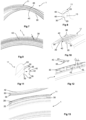
- FIG. 1 shows in a meridian sectional view a rolling assembly according to the invention.
- This assembly has an axis of rotation X-X', it comprises two expanders 1, a tire 2 and a rim 3.
- the tire 2 has two beads 21.
- the rim 3 has two rim seats 31, each extended by a rim flange 32.
- the rim flange 32 has a radially outer bearing face 29 intended to serve as a support for the body of the expander.
- the bearing face 29 of the rim flange 32 is in contact with the expander 1 when the tire is mounted on the expanders and the latter are mounted on the rim, the tire being inflated to the nominal pressure.
- the extender 1 comprises an axially inner end 10 intended to be mounted on one of said rim seats 31. It comprises an axially outer end 11 provided with an outer reinforcing element 15, which is annular in shape, produced for example from a cable winding, as well as a body 12 oriented substantially axially and arranged between said axially outer end 11 and said axially inner end 10.
- the axially inner end 10 of the extender has an axial positioning face substantially perpendicular to the axis of rotation X-X', and is immobilized by being pressed axially against the rim flange 32, under the effect of the inflation pressure of the tire 2 and thanks to a groove in the rim containing it.
- the axially outer end 11 has a shoulder 16 forming a face substantially perpendicular to the axis of rotation X-X'.
- Said extender 1 comprises a seat on extender 14 which receives the bead 21 of the tire.
- the bead 21 is immobilized by being pressed axially on said seat 14 against said shoulder 16 of the axially outer end 11 of the extender, under the effect of the inflation pressure of the tire.
- the assembly is carried out by arranging the extender 1 on the rim 3 and then mounting the tire 2 on the extender 1. Once the assembly is carried out, the bead of the tire imposes a circumferential contraction of the extender 1.
- FIG. 2 illustrates a partial front view of an extender 1 according to a first embodiment.
- the figures 3, 4, 5 and 6 present, in partial meridian section, different variants of the extender according to the first embodiment of the invention.
- the extender 1 comprises inserts 40 fixed in a circumferential row of cavities 20 each provided with means removable fixing of each insert 40 inside a cavity 20. This gives a circumferential row of inserts 40 uniformly distributed over the circumference of the front face 30, which is a visible face of the extender 1, being spaced by a pitch “p” from each other ( fig 2 ).
- the means for removable attachment of the insert to the axially outer end of the expander comprise means for attachment by reversible elastic fitting of the inserts in the cavity or cavities of the axially outer end of the expander.
- the pitch p is greater than twice the diameter of the visible part of the inserts 40.
- the cavity 20 has a generally spherical shape, it is made so as to be able to receive a spherical insert 40 or ball preferably having a diameter of between 3 and 5 mm. Even more preferably, a ball will be chosen having the largest possible diameter permitted by the size, because this ensures a better interface with the cavity, and therefore a better hold of the insert, while having a fairly visible protruding part.
- the depth of a cavity 20 is less than its diameter, but greater than its radius, which ensures good hold of the insert 40 in the cavity 20, while allowing it to have a protruding part, relative to the flat surface of the front face 30, and therefore visible.
- the insert 40 of spherical shape of the Figure 3 has a diameter of 3 mm and it projects by approximately 0.6 mm from the flat surface of the front face 30.
- FIGS. 4, 5 and 6 illustrate cavities 20 made so as to cooperate with inserts 40 comprising removable fixing means 35 of hook type thus allowing fixing by reversible elastic clipping of each insert 40 in a cavity 20.
- An insert 40 according to these variants is a part of revolution comprising a head 41, which is the part having the largest section and is connected to a fixing base 43 by a rod 42.
- the fixing base 43 comprises an end 44 of truncated cone shape forming a hook and ensuring the fixing of the insert inside a cavity 20.
- the head 41 may have a diameter of 5 mm, the rod 42 a diameter of 2 mm and the fixing base 43 an end forming the small base of the cone of 2.4 mm extended towards the front by a wall inclined by approximately 15°.
- the fixing bases of the 40 inserts of the figures 4 to 6 are identical, these inserts being different from each other rather by the shape and dimensions of their head 41.
- the head 41 of the insert of the Figure 4 is very protruding, it has the shape of a half-sphere.
- the head 41 of the insert of the Figure 5 is more flattened than the previous one, it has the shape of a spherical cap protruding with its edges in relation to the surface of the front face 30.
- the head 41 of the insert of the Figure 6 also has a spherical cap shape like that of the Figure 5 , but it is less protruding than this, having the edges buried below the surface of the front face 30.
- the depth h of an insert 40 is preferably greater than its radius d/2 and less than its diameter d, where d is the maximum diameter of the insert and h is the burial depth of the insert measured from the surface of the front face 30.
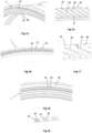
- THE figures 7 and 8 illustrate an expander 1 according to a second embodiment of the invention.
- the expander 1 comprises two coaxial rows of cavities 20 in which the inserts 40 are fixed.
- the neighboring cavities 20 of the two rows may be located in the same radial direction, at the two ends of the front face 30 ( fig. 8 ).
- the cavities 20 of a row are arranged in a staggered manner relative to the cavities 20 of the neighboring row (it is understood that the centers of the cavities of a row are angularly offset relative to the centers of the cavities of the neighboring row as seen in a front view of the expander), which makes it possible to better distribute the inserts on the front face 30 of the expander.
- the removable fixing means are of the same type as those described with reference to figures 1 to 6 .
- FIG. 9 to 13 illustrate variants of an extender 1 according to a third embodiment of the invention.
- the cavities 20 of the extender 1 are uniformly distributed over the circumference of the front face 30 in two coaxial rows of cavities.
- the cavities have a generally spherical shape to cooperate with removable fixing means 35 of spherical shape of the inserts 40.
- a insert 40 according to this embodiment comprises a plate 42 of generally flat shape on its upper face, visible on the front face 30 of the extender, being provided with removable fixing means on its lower face.
- Figure 10 illustrates a variant of the extender comprising inserts 40 each made in the form of an elongated flat plate provided with two removable fixing bulbs (forming the removable fixing means of the inserts) with axes perpendicular to the plate at its ends.
- Figure 11 illustrates a variant in which the front face 30 of the axially outer end 11 of the extender comprises a cutout 25 in which the plate 42 of the insert 40 is completely inserted when it is brought, in the direction of the arrow illustrated in the figure, to be fixed in the cavities 20.
- the Figure 12 illustrates another variant embodiment in which the plate 42 has the general shape of an equilateral triangle provided with three bulbs (or spheres) for fixing in three corresponding cavities 20 of spherical shape of the expander 1. After fixing the inserts, a gap “i” is thus formed between two plates 42 of two adjacent inserts 40, a gap made from an elastomeric material and therefore flexible.
- the dimensions of the gap i are chosen to be sufficiently small to allow local deformation of the expander, while having a visual impression of a circle formed by the adjacent inserts.
- the values of the gap i are between 2 and 5 mm.
- Figure 13 illustrates another alternative embodiment in which the plate 42 has a planar arcuate shape and comprises several fixing bulbs in spherical cavities 20 of the expander 1.
- a gap i also exists for the same reasons as in the previously described variants between two adjacent plates 42.
- the insert 40 is fixed by simple axial pressure on the front face 30 of the expander, in the direction of the arrows in the figure.
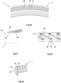
- THE figures 14 to 19 illustrate different variants of an expander according to a fourth embodiment of the invention.
- the cavities of the expander according to this embodiment are produced in the form of a plurality of grooves 50 uniformly distributed over the circumference of the front face 30 and each forming a constant angle with a radial direction.
- the grooves 50 are spaced apart by a pitch p equal to or greater than the width of a groove as measured on the axially outermost surface thereof.
- the grooves are inclined relative to the radial direction, they form an angle of approximately 40° with it.
- the grooves are arranged according to the radial direction of the expander.
- the cross-section of the grooves 50 has a substantially dovetail shape.
- substantially dovetailed is meant a dovetailed section, as illustrated in Figure 15 , or T-shaped, as shown in Figure 17 or even in the shape of an arched T, as best seen in the figure 19 .
- the inserts 40 have a generally elongated shape, they have the width of the groove 50 and a cross-section of shape corresponding to that of the groove 50, as illustrated in figures 16, 17 and 18 .
- the grooves 50 have an open radially inner end 51 and a closed radially outer end 52. As best seen in the Figure 17 , the outer end 52 of the groove 50 is located radially set back by a distance “e” relative to the radially outer end 34 of the axially outer end 11 of the expander.
- the length of an insert 40 is approximately 10 mm
- the distance d approximately 4 to 5 mm
- the width of the insert, and therefore of the upper part of the groove 50 is approximately 2 mm
- that of the fixing base (the width of the T or of the base of the groove 50) approximately 3.4 mm.
- THE figures 20, 21 and 23 illustrate an extender 1 according to a fifth embodiment.
- the inserts 40 are of the “staple” type, they therefore have a flat elongated part 30', visible on the front face 30 of the extender, and two fixing tabs 30" in two parallel cavities 20 of corresponding shape.
- the end of each tab 30" has a hook shape 30"'.
- FIG 23 illustrates an expander 1 according to a sixth embodiment of the invention.
- the front face 30 of the expander comprises a single circumferential cavity 20' whose section is such that it allows the removable attachment of several inserts 40.
- the inserts 40 are spheres, force-fitted in the cavity 20', the inserts being connected to each other by a flexible link 49, which makes it possible to form a single piece that is easier to mount in the cavity 20', while allowing local deformation of the expander accommodated at the level of the flexible links.
- spherical impressions of diameter comparable to that of the inserts and substantially different from the width of the cavity are made on its periphery, making it possible to better accommodate spherical-shaped inserts.
- the inserts 40 are preferably metallic, for example made of stainless steel. In one variant, they are made of a metallized plastic material. In another variant, they are made of a colored plastic material. In yet another variant, the upper face of the insert comprises a letter or symbol or part of a letter or symbol (which allows, for example, several adjacent inserts to form a word or symbol, for example that representing the make of the automobile on which the rolling assembly is mounted).
- the solution of the invention offers the user the possibility of changing the design of the extender at any time by choosing the inserts he wants.
Landscapes
- Engineering & Computer Science (AREA)
- Mechanical Engineering (AREA)
- Prostheses (AREA)
- Tires In General (AREA)
Claims (15)
- Expander für eine rollende Einheit mit der Rotationsachse X-X', umfassend einen Reifen (2) mit zwei Wülsten (21) und eine Felge (3), wobei der Expander (100) dazu bestimmt ist, die Verbindung zwischen einem der Wülste (21) und der Felge (3) zu gewährleisten, wobei der Expander (100) ein axial inneres Ende (10), ein axial äußeres Ende (11) und einen Körper (12), der hauptsächlich axial ausgerichtet ist und zwischen dem axial äußeren Ende (11) und dem axial inneren Ende (10) angeordnet ist, umfasst, so dass, wenn er in der Einheit montiert ist, das axial innere Ende (10) dazu bestimmt ist, auf der Felge mithilfe eines inneren Verstärkungselements (17) immobilisiert zu werden, wobei das axial äußere Ende, das ein äußeres Verstärkungselement (15) umfasst, dazu bestimmt ist, einen Wulst (21) des Reifens (2) aufzunehmen, dadurch gekennzeichnet, dass das axial äußere Ende (11) eine Stirnfläche (30) beinhaltet, die mit mehreren Hohlräumen (20) versehen ist, die über ihren Umfang verteilt sind, wobei die Hohlräume an der Fläche offen sind und so ausgeführt sind, dass sie mit Mitteln zur lösbaren Befestigung (35) von mehreren benachbarten Einsätzen (40) zusammenwirken.
- Expander nach Anspruch 1, dadurch gekennzeichnet, dass die Mittel zur lösbaren Befestigung (35) des Einsatzes (40) an dem axial äußeren Ende (11) des Expanders (1) Mittel zur Befestigung durch reversibles elastisches Einstecken der Einsätze (40) in den Hohlraum (20') oder die Hohlräume (20) des axial äußeren Endes (11) des Expanders umfassen.
- Expander nach einem der Ansprüche 1 oder 2, dadurch gekennzeichnet, dass der Hohlraum (20', 20) so ausgeführt ist, dass er mit kugelförmigen Befestigungsmitteln zusammenwirkt.
- Expander nach einem der Ansprüche 1 oder 2, dadurch gekennzeichnet, dass der Hohlraum (20) so ausgeführt ist, dass er mit hakenartigen Befestigungsmitteln zusammenwirkt.
- Expander nach einem der vorhergehenden Ansprüche, dadurch gekennzeichnet, dass er mindestens eine umfängliche Reihe von Hohlräumen (20) umfasst.
- Expander nach einem der Ansprüche 1 bis 4, dadurch gekennzeichnet, dass er zwei koaxiale umfängliche Reihen von Hohlräumen (20) umfasst, wobei die Hohlräume einer Reihe in Bezug auf diejenigen der anderen Reihe winklig versetzt sind.
- Expander nach einem der vorhergehenden Ansprüche, dadurch gekennzeichnet, dass die Hohlräume Nuten (50) sind, die gleichmäßig über den Umfang der Stirnfläche verteilt sind.
- Expander nach Anspruch 7, dadurch gekennzeichnet, dass der Querschnitt der Nuten (50) eine im Wesentlichen schwalbenschwanzartige Form hat.
- Expander nach einem der Ansprüche 7 oder 8, dadurch gekennzeichnet, dass die Nuten (50) ein offenes radial inneres Ende (51) und ein geschlossenes radial äußeres Ende (52) beinhalten.
- Expander nach einem der Ansprüche 7 bis 9, dadurch gekennzeichnet, dass die Nuten (50) radial sind oder jeweils einen konstanten spitzen Winkel mit der radialen Richtung des Expanders bilden.
- Expander nach einem der vorhergehenden Ansprüche, dadurch gekennzeichnet, dass der Hohlraum oder die Hohlräume so ausgeführt sind, das ihr radial äußeres Ende (22) in Bezug auf das radial äußere Ende (34) des axial äußeren Endes (11) des Expanders radial und/oder axial zurückversetzt ist.
- Einsatz (40), der Mittel zur lösbaren Befestigung (35) beinhaltet und dazu bestimmt ist, mit mindestens einem der Hohlräume (20) des Expanders (1) nach einem der vorhergehenden Ansprüche zusammenzuwirken.
- Einsatz nach Anspruch 12, dadurch gekennzeichnet, dass er eine Platte (42) beinhaltet, die mit Mitteln zur Befestigung in mindestens zwei benachbarten Hohlräumen (20) versehen ist.
- Anordnung, die einen Expander (1) nach einem der Ansprüche 1 bis 11 und mehrere Einsätze (40) nach einem der Ansprüche 12 bis 13 beinhaltet.
- Rollende Einheit mit der Rotationsachse X-X', umfassend einen Reifen (2) mit zwei Wülsten (21), eine Felge (3) und einen Expander (1) nach einem der Ansprüche 1 bis 11, der dazu bestimmt ist, die Verbindung zwischen einem der Wülste (21) und der Felge (3) zu gewährleisten, wobei der Expander mit Einsätzen (40) nach einem der Ansprüche 12 bis 13 versehen ist.
Applications Claiming Priority (2)
| Application Number | Priority Date | Filing Date | Title |
|---|---|---|---|
| FR2106039A FR3123588B1 (fr) | 2021-06-08 | 2021-06-08 | Extenseur a stylisme perfectionne et ensemble roulant comportant un tel extenseur |
| PCT/FR2022/051086 WO2022258923A1 (fr) | 2021-06-08 | 2022-06-08 | Extenseur a stylisme perfectionne et ensemble roulant comportant un tel extenseur |
Publications (2)
| Publication Number | Publication Date |
|---|---|
| EP4351891A1 EP4351891A1 (de) | 2024-04-17 |
| EP4351891B1 true EP4351891B1 (de) | 2025-04-02 |
Family
ID=77021517
Family Applications (1)
| Application Number | Title | Priority Date | Filing Date |
|---|---|---|---|
| EP22740941.4A Active EP4351891B1 (de) | 2021-06-08 | 2022-06-08 | Expander mit verbesserter konstruktion und rollende anordnung mit solch einem expander |
Country Status (3)
| Country | Link |
|---|---|
| EP (1) | EP4351891B1 (de) |
| FR (1) | FR3123588B1 (de) |
| WO (1) | WO2022258923A1 (de) |
Family Cites Families (5)
| Publication number | Priority date | Publication date | Assignee | Title |
|---|---|---|---|---|
| JPH08216602A (ja) * | 1995-02-10 | 1996-08-27 | Tomita Auto:Kk | サイドリムプロテクタ |
| GB0213666D0 (en) * | 2002-06-14 | 2002-07-24 | Metcalfe Richard A | A wheel rim assembly |
| FR3026051B1 (fr) * | 2014-09-24 | 2016-11-04 | Michelin & Cie | Adaptateur pour ensemble roulant et ensemble roulant le comprenant |
| FR3053634A3 (fr) | 2016-07-08 | 2018-01-12 | Michelin & Cie | Anneau-enjoliveur pour rebord de jante de vehicule a siege flottant, et ensemble forme par un anneau-enjoliveur et un adapateur pour roue a siege flottant |
| CA3067411A1 (fr) | 2017-06-30 | 2019-01-03 | Compagnie Generale Des Etablissements Michelin | Ensemble roulant comportant une jante dont le rebord forme un support de largeur axiale etendue |
-
2021
- 2021-06-08 FR FR2106039A patent/FR3123588B1/fr active Active
-
2022
- 2022-06-08 WO PCT/FR2022/051086 patent/WO2022258923A1/fr not_active Ceased
- 2022-06-08 EP EP22740941.4A patent/EP4351891B1/de active Active
Also Published As
| Publication number | Publication date |
|---|---|
| FR3123588B1 (fr) | 2024-03-08 |
| WO2022258923A1 (fr) | 2022-12-15 |
| EP4351891A1 (de) | 2024-04-17 |
| FR3123588A1 (fr) | 2022-12-09 |
Similar Documents
| Publication | Publication Date | Title |
|---|---|---|
| EP3017967B1 (de) | Landwirtschaftsreifen | |
| EP3481650B1 (de) | Ringverzierung für rad mit schwimmendem reifensitz | |
| EP2145775B1 (de) | Halbhohlreifen und entsprechende Radfelge, insbesondere für Landwirtschaftsmaschinen | |
| EP3589503B1 (de) | Reifenlauffläche für einen lkw-anhänger | |
| EP3017669B2 (de) | Verbessertes rad für landwirtschaftliche verwendung | |
| LU83690A1 (fr) | Ensemble jante et adaptateur de pneu | |
| EP1897705A1 (de) | Runflat-Vorrichtung für Kraftfahrzeug und damit ausgestattete montierte Einheit | |
| EP3075220B1 (de) | Reifen für ackerwalze, und mit einem solchen reifen ausgestattete ackerwalze | |
| FR2978896A1 (fr) | Machine agricole a roue et rouleau adapte | |
| EP2982229B1 (de) | Landwirtschaftliches werkzeug mit verbessertem reifen | |
| EP1810560B1 (de) | Domreifen für landwirtschaftliche Maschine | |
| WO2015086447A1 (fr) | Pneumatique comportant un element graphique particulier | |
| EP4351891B1 (de) | Expander mit verbesserter konstruktion und rollende anordnung mit solch einem expander | |
| WO2004110790A1 (fr) | Bande de roulement comportant une nervure sacrifiee ventilee | |
| EP4210969B1 (de) | Vorrichtung zum schutz einer reifenseitenwand | |
| WO2003008208A1 (fr) | Jante pour cycle et ensemble monte tubeless pour cycle | |
| EP3802151B1 (de) | Flexibler adapter und felgenanordnung für eine rollanordnung | |
| CA2475417A1 (fr) | Methode pour alleger un dispositif de roulage a plat de roue de vehicule automobile et dispositif ainsi obtenu | |
| EP3984782B1 (de) | Bausatz zum erstellen eines landwirtschaftlichen geräts aus einem radkörper oder einem rohrförmigen träger | |
| EP3695698A1 (de) | Verbessertes druckrad und reifen für ein solches rad | |
| FR3130199A1 (fr) | Extenseur a stylisme ameliore et ensemble roulant comportant un tel extenseur | |
| FR3078922A1 (fr) | Roue structurelle de vehicule a effet aerodynamique et vehicule comprenant une telle roue | |
| FR2879126A1 (fr) | Roue allegee en particulier pour machines agricoles | |
| EP4351890A1 (de) | Verbesserter adapter und rollende anordnung mit einem solchen adapter | |
| CA3121666A1 (fr) | Extenseur perfectionne et ensemble roulant comportant un tel extenseur |
Legal Events
| Date | Code | Title | Description |
|---|---|---|---|
| STAA | Information on the status of an ep patent application or granted ep patent |
Free format text: STATUS: UNKNOWN |
|
| STAA | Information on the status of an ep patent application or granted ep patent |
Free format text: STATUS: THE INTERNATIONAL PUBLICATION HAS BEEN MADE |
|
| PUAI | Public reference made under article 153(3) epc to a published international application that has entered the european phase |
Free format text: ORIGINAL CODE: 0009012 |
|
| STAA | Information on the status of an ep patent application or granted ep patent |
Free format text: STATUS: REQUEST FOR EXAMINATION WAS MADE |
|
| 17P | Request for examination filed |
Effective date: 20240108 |
|
| AK | Designated contracting states |
Kind code of ref document: A1 Designated state(s): AL AT BE BG CH CY CZ DE DK EE ES FI FR GB GR HR HU IE IS IT LI LT LU LV MC MK MT NL NO PL PT RO RS SE SI SK SM TR |
|
| DAV | Request for validation of the european patent (deleted) | ||
| DAX | Request for extension of the european patent (deleted) | ||
| GRAP | Despatch of communication of intention to grant a patent |
Free format text: ORIGINAL CODE: EPIDOSNIGR1 |
|
| STAA | Information on the status of an ep patent application or granted ep patent |
Free format text: STATUS: GRANT OF PATENT IS INTENDED |
|
| INTG | Intention to grant announced |
Effective date: 20241127 |
|
| GRAS | Grant fee paid |
Free format text: ORIGINAL CODE: EPIDOSNIGR3 |
|
| GRAA | (expected) grant |
Free format text: ORIGINAL CODE: 0009210 |
|
| STAA | Information on the status of an ep patent application or granted ep patent |
Free format text: STATUS: THE PATENT HAS BEEN GRANTED |
|
| AK | Designated contracting states |
Kind code of ref document: B1 Designated state(s): AL AT BE BG CH CY CZ DE DK EE ES FI FR GB GR HR HU IE IS IT LI LT LU LV MC MK MT NL NO PL PT RO RS SE SI SK SM TR |
|
| REG | Reference to a national code |
Ref country code: GB Ref legal event code: FG4D Free format text: NOT ENGLISH |
|
| REG | Reference to a national code |
Ref country code: CH Ref legal event code: EP |
|
| REG | Reference to a national code |
Ref country code: IE Ref legal event code: FG4D Free format text: LANGUAGE OF EP DOCUMENT: FRENCH |
|
| REG | Reference to a national code |
Ref country code: DE Ref legal event code: R096 Ref document number: 602022012649 Country of ref document: DE |
|
| PGFP | Annual fee paid to national office [announced via postgrant information from national office to epo] |
Ref country code: DE Payment date: 20250618 Year of fee payment: 4 |
|
| PGFP | Annual fee paid to national office [announced via postgrant information from national office to epo] |
Ref country code: FR Payment date: 20250627 Year of fee payment: 4 |
|
| PGFP | Annual fee paid to national office [announced via postgrant information from national office to epo] |
Ref country code: AT Payment date: 20250721 Year of fee payment: 4 |
|
| REG | Reference to a national code |
Ref country code: NL Ref legal event code: MP Effective date: 20250402 |
|
| PG25 | Lapsed in a contracting state [announced via postgrant information from national office to epo] |
Ref country code: NL Free format text: LAPSE BECAUSE OF FAILURE TO SUBMIT A TRANSLATION OF THE DESCRIPTION OR TO PAY THE FEE WITHIN THE PRESCRIBED TIME-LIMIT Effective date: 20250402 |
|
| REG | Reference to a national code |
Ref country code: AT Ref legal event code: MK05 Ref document number: 1780957 Country of ref document: AT Kind code of ref document: T Effective date: 20250402 |
|
| PG25 | Lapsed in a contracting state [announced via postgrant information from national office to epo] |
Ref country code: FI Free format text: LAPSE BECAUSE OF FAILURE TO SUBMIT A TRANSLATION OF THE DESCRIPTION OR TO PAY THE FEE WITHIN THE PRESCRIBED TIME-LIMIT Effective date: 20250402 Ref country code: PT Free format text: LAPSE BECAUSE OF FAILURE TO SUBMIT A TRANSLATION OF THE DESCRIPTION OR TO PAY THE FEE WITHIN THE PRESCRIBED TIME-LIMIT Effective date: 20250804 Ref country code: ES Free format text: LAPSE BECAUSE OF FAILURE TO SUBMIT A TRANSLATION OF THE DESCRIPTION OR TO PAY THE FEE WITHIN THE PRESCRIBED TIME-LIMIT Effective date: 20250402 |
|
| REG | Reference to a national code |
Ref country code: LT Ref legal event code: MG9D |
|
| PG25 | Lapsed in a contracting state [announced via postgrant information from national office to epo] |
Ref country code: GR Free format text: LAPSE BECAUSE OF FAILURE TO SUBMIT A TRANSLATION OF THE DESCRIPTION OR TO PAY THE FEE WITHIN THE PRESCRIBED TIME-LIMIT Effective date: 20250703 Ref country code: NO Free format text: LAPSE BECAUSE OF FAILURE TO SUBMIT A TRANSLATION OF THE DESCRIPTION OR TO PAY THE FEE WITHIN THE PRESCRIBED TIME-LIMIT Effective date: 20250702 |
|
| PG25 | Lapsed in a contracting state [announced via postgrant information from national office to epo] |
Ref country code: PL Free format text: LAPSE BECAUSE OF FAILURE TO SUBMIT A TRANSLATION OF THE DESCRIPTION OR TO PAY THE FEE WITHIN THE PRESCRIBED TIME-LIMIT Effective date: 20250402 |
|
| PG25 | Lapsed in a contracting state [announced via postgrant information from national office to epo] |
Ref country code: BG Free format text: LAPSE BECAUSE OF FAILURE TO SUBMIT A TRANSLATION OF THE DESCRIPTION OR TO PAY THE FEE WITHIN THE PRESCRIBED TIME-LIMIT Effective date: 20250402 |
|
| PG25 | Lapsed in a contracting state [announced via postgrant information from national office to epo] |
Ref country code: AT Free format text: LAPSE BECAUSE OF FAILURE TO SUBMIT A TRANSLATION OF THE DESCRIPTION OR TO PAY THE FEE WITHIN THE PRESCRIBED TIME-LIMIT Effective date: 20250402 Ref country code: HR Free format text: LAPSE BECAUSE OF FAILURE TO SUBMIT A TRANSLATION OF THE DESCRIPTION OR TO PAY THE FEE WITHIN THE PRESCRIBED TIME-LIMIT Effective date: 20250402 |
|
| PG25 | Lapsed in a contracting state [announced via postgrant information from national office to epo] |
Ref country code: RS Free format text: LAPSE BECAUSE OF FAILURE TO SUBMIT A TRANSLATION OF THE DESCRIPTION OR TO PAY THE FEE WITHIN THE PRESCRIBED TIME-LIMIT Effective date: 20250702 |
|
| PG25 | Lapsed in a contracting state [announced via postgrant information from national office to epo] |
Ref country code: IS Free format text: LAPSE BECAUSE OF FAILURE TO SUBMIT A TRANSLATION OF THE DESCRIPTION OR TO PAY THE FEE WITHIN THE PRESCRIBED TIME-LIMIT Effective date: 20250802 |
|
| PG25 | Lapsed in a contracting state [announced via postgrant information from national office to epo] |
Ref country code: LV Free format text: LAPSE BECAUSE OF FAILURE TO SUBMIT A TRANSLATION OF THE DESCRIPTION OR TO PAY THE FEE WITHIN THE PRESCRIBED TIME-LIMIT Effective date: 20250402 |
|
| REG | Reference to a national code |
Ref country code: DE Ref legal event code: R097 Ref document number: 602022012649 Country of ref document: DE |
|
| PG25 | Lapsed in a contracting state [announced via postgrant information from national office to epo] |
Ref country code: DK Free format text: LAPSE BECAUSE OF FAILURE TO SUBMIT A TRANSLATION OF THE DESCRIPTION OR TO PAY THE FEE WITHIN THE PRESCRIBED TIME-LIMIT Effective date: 20250402 Ref country code: SM Free format text: LAPSE BECAUSE OF FAILURE TO SUBMIT A TRANSLATION OF THE DESCRIPTION OR TO PAY THE FEE WITHIN THE PRESCRIBED TIME-LIMIT Effective date: 20250402 |
|
| PG25 | Lapsed in a contracting state [announced via postgrant information from national office to epo] |
Ref country code: CZ Free format text: LAPSE BECAUSE OF FAILURE TO SUBMIT A TRANSLATION OF THE DESCRIPTION OR TO PAY THE FEE WITHIN THE PRESCRIBED TIME-LIMIT Effective date: 20250402 |
|
| PG25 | Lapsed in a contracting state [announced via postgrant information from national office to epo] |
Ref country code: EE Free format text: LAPSE BECAUSE OF FAILURE TO SUBMIT A TRANSLATION OF THE DESCRIPTION OR TO PAY THE FEE WITHIN THE PRESCRIBED TIME-LIMIT Effective date: 20250402 |
|
| PG25 | Lapsed in a contracting state [announced via postgrant information from national office to epo] |
Ref country code: SK Free format text: LAPSE BECAUSE OF FAILURE TO SUBMIT A TRANSLATION OF THE DESCRIPTION OR TO PAY THE FEE WITHIN THE PRESCRIBED TIME-LIMIT Effective date: 20250402 |
|
| REG | Reference to a national code |
Ref country code: CH Ref legal event code: H13 Free format text: ST27 STATUS EVENT CODE: U-0-0-H10-H13 (AS PROVIDED BY THE NATIONAL OFFICE) Effective date: 20260127 |
|
| PG25 | Lapsed in a contracting state [announced via postgrant information from national office to epo] |
Ref country code: IT Free format text: LAPSE BECAUSE OF FAILURE TO SUBMIT A TRANSLATION OF THE DESCRIPTION OR TO PAY THE FEE WITHIN THE PRESCRIBED TIME-LIMIT Effective date: 20250402 |
|
| PG25 | Lapsed in a contracting state [announced via postgrant information from national office to epo] |
Ref country code: MC Free format text: LAPSE BECAUSE OF FAILURE TO SUBMIT A TRANSLATION OF THE DESCRIPTION OR TO PAY THE FEE WITHIN THE PRESCRIBED TIME-LIMIT Effective date: 20250402 |
|
| PLBE | No opposition filed within time limit |
Free format text: ORIGINAL CODE: 0009261 |
|
| STAA | Information on the status of an ep patent application or granted ep patent |
Free format text: STATUS: NO OPPOSITION FILED WITHIN TIME LIMIT |
|
| REG | Reference to a national code |
Ref country code: CH Ref legal event code: L10 Free format text: ST27 STATUS EVENT CODE: U-0-0-L10-L00 (AS PROVIDED BY THE NATIONAL OFFICE) Effective date: 20260211 |
|
| PG25 | Lapsed in a contracting state [announced via postgrant information from national office to epo] |
Ref country code: LU Free format text: LAPSE BECAUSE OF NON-PAYMENT OF DUE FEES Effective date: 20250608 |
|
| REG | Reference to a national code |
Ref country code: BE Ref legal event code: MM Effective date: 20250630 |
|
| PG25 | Lapsed in a contracting state [announced via postgrant information from national office to epo] |
Ref country code: RO Free format text: LAPSE BECAUSE OF FAILURE TO SUBMIT A TRANSLATION OF THE DESCRIPTION OR TO PAY THE FEE WITHIN THE PRESCRIBED TIME-LIMIT Effective date: 20250402 |
|
| 26N | No opposition filed |
Effective date: 20260105 |
|
| PG25 | Lapsed in a contracting state [announced via postgrant information from national office to epo] |
Ref country code: IE Free format text: LAPSE BECAUSE OF NON-PAYMENT OF DUE FEES Effective date: 20250608 |
|
| PG25 | Lapsed in a contracting state [announced via postgrant information from national office to epo] |
Ref country code: BE Free format text: LAPSE BECAUSE OF NON-PAYMENT OF DUE FEES Effective date: 20250630 |