EP4351448B1 - Abwinkelbarer schaft für ein medizinisches handinstrument - Google Patents
Abwinkelbarer schaft für ein medizinisches handinstrument Download PDFInfo
- Publication number
- EP4351448B1 EP4351448B1 EP22757494.4A EP22757494A EP4351448B1 EP 4351448 B1 EP4351448 B1 EP 4351448B1 EP 22757494 A EP22757494 A EP 22757494A EP 4351448 B1 EP4351448 B1 EP 4351448B1
- Authority
- EP
- European Patent Office
- Prior art keywords
- shaft
- shaft section
- flexible
- distal
- section
- Prior art date
- Legal status (The legal status is an assumption and is not a legal conclusion. Google has not performed a legal analysis and makes no representation as to the accuracy of the status listed.)
- Active
Links
Images




Classifications
-
- A—HUMAN NECESSITIES
- A61—MEDICAL OR VETERINARY SCIENCE; HYGIENE
- A61B—DIAGNOSIS; SURGERY; IDENTIFICATION
- A61B17/00—Surgical instruments, devices or methods
- A61B17/28—Surgical forceps
- A61B17/29—Forceps for use in minimally invasive surgery
-
- A—HUMAN NECESSITIES
- A61—MEDICAL OR VETERINARY SCIENCE; HYGIENE
- A61B—DIAGNOSIS; SURGERY; IDENTIFICATION
- A61B1/00—Instruments for performing medical examinations of the interior of cavities or tubes of the body by visual or photographical inspection, e.g. endoscopes; Illuminating arrangements therefor
- A61B1/005—Flexible endoscopes
- A61B1/0051—Flexible endoscopes with controlled bending of insertion part
- A61B1/0057—Constructional details of force transmission elements, e.g. control wires
-
- A—HUMAN NECESSITIES
- A61—MEDICAL OR VETERINARY SCIENCE; HYGIENE
- A61B—DIAGNOSIS; SURGERY; IDENTIFICATION
- A61B1/00—Instruments for performing medical examinations of the interior of cavities or tubes of the body by visual or photographical inspection, e.g. endoscopes; Illuminating arrangements therefor
- A61B1/00112—Connection or coupling means
- A61B1/00121—Connectors, fasteners and adapters, e.g. on the endoscope handle
- A61B1/00128—Connectors, fasteners and adapters, e.g. on the endoscope handle mechanical, e.g. for tubes or pipes
-
- A—HUMAN NECESSITIES
- A61—MEDICAL OR VETERINARY SCIENCE; HYGIENE
- A61B—DIAGNOSIS; SURGERY; IDENTIFICATION
- A61B17/00—Surgical instruments, devices or methods
- A61B17/16—Instruments for performing osteoclasis; Drills or chisels for bones; Trepans
- A61B17/1613—Component parts
- A61B17/1633—Sleeves, i.e. non-rotating parts surrounding the bit shaft, e.g. the sleeve forming a single unit with the bit shaft
-
- A—HUMAN NECESSITIES
- A61—MEDICAL OR VETERINARY SCIENCE; HYGIENE
- A61B—DIAGNOSIS; SURGERY; IDENTIFICATION
- A61B17/00—Surgical instruments, devices or methods
- A61B17/32—Surgical cutting instruments
- A61B17/320016—Endoscopic cutting instruments, e.g. arthroscopes, resectoscopes
- A61B17/32002—Endoscopic cutting instruments, e.g. arthroscopes, resectoscopes with continuously rotating, oscillating or reciprocating cutting instruments
-
- A—HUMAN NECESSITIES
- A61—MEDICAL OR VETERINARY SCIENCE; HYGIENE
- A61B—DIAGNOSIS; SURGERY; IDENTIFICATION
- A61B17/00—Surgical instruments, devices or methods
- A61B17/16—Instruments for performing osteoclasis; Drills or chisels for bones; Trepans
- A61B17/1613—Component parts
- A61B17/1631—Special drive shafts, e.g. flexible shafts
-
- A—HUMAN NECESSITIES
- A61—MEDICAL OR VETERINARY SCIENCE; HYGIENE
- A61B—DIAGNOSIS; SURGERY; IDENTIFICATION
- A61B17/00—Surgical instruments, devices or methods
- A61B17/16—Instruments for performing osteoclasis; Drills or chisels for bones; Trepans
- A61B17/1662—Instruments for performing osteoclasis; Drills or chisels for bones; Trepans for particular parts of the body
- A61B17/1671—Instruments for performing osteoclasis; Drills or chisels for bones; Trepans for particular parts of the body for the spine
-
- A—HUMAN NECESSITIES
- A61—MEDICAL OR VETERINARY SCIENCE; HYGIENE
- A61B—DIAGNOSIS; SURGERY; IDENTIFICATION
- A61B17/00—Surgical instruments, devices or methods
- A61B17/28—Surgical forceps
- A61B17/29—Forceps for use in minimally invasive surgery
- A61B2017/2926—Details of heads or jaws
- A61B2017/2927—Details of heads or jaws the angular position of the head being adjustable with respect to the shaft
-
- A—HUMAN NECESSITIES
- A61—MEDICAL OR VETERINARY SCIENCE; HYGIENE
- A61B—DIAGNOSIS; SURGERY; IDENTIFICATION
- A61B17/00—Surgical instruments, devices or methods
- A61B17/32—Surgical cutting instruments
- A61B17/320016—Endoscopic cutting instruments, e.g. arthroscopes, resectoscopes
- A61B17/32002—Endoscopic cutting instruments, e.g. arthroscopes, resectoscopes with continuously rotating, oscillating or reciprocating cutting instruments
- A61B2017/320032—Details of the rotating or oscillating shaft, e.g. using a flexible shaft
Definitions
- the present disclosure relates to a shaft of or for a medical hand instrument.
- milling handpieces There are also already manufacturers of angled milling handpieces/medical hand instruments. These are mainly used for endoscopic procedures on the spine and enable minimally invasive techniques as well as easy processing of difficult-to-access structures in this area.
- the joint constructions of these milling handpieces have a rather open design and have a certain degree of flexibility in terms of angle. This means that when pressure is applied to the milling tip, the angle changes slightly.
- these milling handpieces only allow angles of up to 36°.
- One example of this is milling handpieces from Joimax.
- cordless screwdrivers with an inclined plane.
- cordless screwdrivers with an angled head have a similar swivel joint to the one described below and have a very good force absorption of the angle (rigid joint).
- angles of up to 90° are possible.
- the cordless screwdrivers have to be adjusted from the outside. They therefore do not have internal control.
- a handpiece can be chosen between three variants: 0°, 7.5° and 15° angles.
- the biggest disadvantage is the large bending radius used to achieve the angle. This takes up a lot of space and limits the options for action in the surgical field.
- the angle cannot be adjusted intraoperatively. Due to the fixed angle, endoscopic work with the angled shafts is not possible, as they cannot be inserted into the straight working channel of the endoscope. Furthermore, the maximum angle of 15° is not particularly large.
- a milling cutter with a distal and a proximal shaft section is known, which can be rotated relative to each other in such a way that the two shaft sections can be angled relative to each other by their inclined front sides.
- the two shaft sections are angled relative to each other by a bevel gear.
- the RU 2 181 566 C2 discloses a bendable hand instrument.
- a tubular intermediate section has a toothing at each end of the intermediate section.
- the toothing meshes with a corresponding toothing on a distal and a proximal shaft section, wherein the distal shaft section can be bent relative to the proximal shaft section by rotation about a longitudinal axis.
- the distal and the proximal shaft section each have inclined front sides by which the shaft sections can be bent.
- the US 6 050 989 A shows a surgical handpiece with an angled distal bushing.
- the distal bushing is rotatable relative to a proximal bushing, with the distal and proximal bushings being connected to one another via a spring-loaded connecting element.
- US 5 575 799 A also shows a surgical handpiece with an angled distal tip. The distal tip can be rotated relative to a proximal shaft section by means of bevel gear teeth and can be angled by means of inclined front sides.
- the object of the disclosure is therefore to overcome the disadvantages of the prior art and to provide a shaft for a medical hand instrument in which a distal shaft section can be angled during operation and the angle between the distal shaft section and a proximal shaft section does not change even under load.
- the shaft of the hand instrument should be able to be angled by means of a simple and error-resistant mechanism.
- the disclosure therefore relates to a shaft for a medical hand instrument with a distal shaft section and a proximal shaft section, the front sides of which face each other, at least one of which is set at an angle of attack other than 90° with respect to the respective shaft longitudinal axis, so that different shaft shapes result depending on the relative rotational position of the two shaft sections.
- the pinion is connected to the adjustment bushing in the distal shaft section in a rotationally transmitting manner by a flexible transmission element.
- the flexible transmission element can preferably be a rotating shaft or a sheet metal (strip) that rotates around a longitudinal axis either concentrically or in an orbital manner (i.e. on an orbit).
- the pinion is connected to the flexible transmission element.
- the connection can be made, for example, by welding and/or gluing or another detachable or non-detachable joining technique.
- the adjustment bushing can preferably be attached to the side of the flexible transmission element facing away from the pinion. This connection can also be made by welding or gluing.
- the flexible transmission element transfers the rotation of the pinion to the adjustment bushing.
- the shaft has a bendable distal shaft section.
- the distal shaft section and the proximal shaft section each have a slanted end/angle that is inclined relative to the respective shaft section axis. front side.
- the bevels/angled end sections/front sides each have essentially the same angle of attack. Therefore, the bevels fit together in such a way that the proximal and distal shaft sections form a straight shaft/straight tube in a certain relative rotational position. If the distal shaft section rotates about its longitudinal axis relative to the proximal shaft section and the proximal shaft section remains stationary, the distal shaft section is inevitably angled by the angled front sides/end sections.
- the distal shaft section of the medical hand instrument can be bent during operation. This means that it is possible to bend the distal shaft section during an operation. Because the distal shaft section rests on the bevel/angled front side of the proximal shaft section, the distal shaft section is firmly supported.
- the medical hand instrument preferably has an adjustment wheel, the (adjusted) proximal shaft section, the distal shaft section that can be bent relative thereto, a flexible milling cutter and a bearing.
- the proximal shaft section has a fixed outer tube, a hollow wheel (with an internal toothing), a eccentric locking bushing and a pinion (with external teeth that mesh with the internal teeth of the ring gear) that meshes with the ring gear.
- the relatively bendable distal shaft section further preferably has a flexible transmission element, an adjustment bushing with a driving pin and a distal shaft tip.
- the distal shaft section is preferably mounted on the proximal section with the bearing.
- the flexible milling cutter is preferably guided through the proximal shaft section and the distal shaft section and can be bent together with the distal shaft section.
- the adjustment bushing is preferably connected to the pinion by the flexible transmission element in such a way that a rotational movement of the pinion is transmitted to the adjustment bushing.
- the adjustment bushing preferably transmits the rotation through the driving pin to the distal shaft tip.
- the proximal shaft section has the ring gear with the internal toothing that meshes with the external toothing of the pinion.
- the proximal shaft section preferably has the fixed outer tube with the angled end face.
- the ring gear is mounted in the fixed outer tube so as to be rotatable about its longitudinal axis.
- the ring gear can preferably be operated from the proximal end section of the shaft and has the internal toothing.
- the internal toothing meshes with the external toothing of the pinion. In other words, the internal toothing is in operative engagement with the external toothing. As a result, rotation of the ring gear is transmitted to the pinion.
- the adjustment bushing has the driving pin, which is positively connected to the distal shaft tip and transfers the rotation of the adjustment bushing to the distal shaft tip.
- the adjustment bushing is preferably connected to the distal shaft tip by the driving pin. The rotation of the adjustment bushing is thereby transferred to the distal shaft tip and the distal shaft tip is rotated. In the end, the distal shaft tip is therefore preferably rotated along with the ring gear. By rotating the distal shaft tip, the adjusted front sides of the distal shaft section and the proximal shaft section against each other in such a way that the distal shaft section is angled.
- the proximal shaft portion has an eccentric locking bushing.
- the eccentric locking bushing is preferably mounted in the outer tube.
- the eccentric locking bushing presses the pinion against a side of the outer tube opposite the eccentric locking bushing.
- the pinion is preferably on the side of the shaft into which the distal shaft portion is not bent.
- the pinion is driven by the ring gear and rotates in the eccentric locking bushing.
- the pinion is always arranged on the side of the outer tube. Since the pinion is preferably arranged on the side into which the distal shaft portion does not bend, the flexible transmission element is further away from the flexible cutter.
- the flexible transmission element is a flexible spring plate, preferably with a ball attached to the side.
- the flexible transmission element can be designed as a wobbling/circularly rotating plate.
- the spring plate rotates with the pinion, it does not rotate about its own longitudinal axis, but wobbles about a longitudinal axis of the pinion.
- the spring plate is furthest away from the flexible milling cutter in the 45° angled position. This minimizes the risk of a collision and the structure of the shaft can be made smaller.
- the ball of the flexible spring plate is received in a spherical receiving groove in the pinion and the side of the spring plate opposite the ball is preferably connected to the adjusting bush.
- the ball of the flexible spring plate is received in a spherical receiving groove in the pinion and the side of the flexible spring plate opposite the ball is preferably connected to the pinion.
- the ball is preferably movably accommodated in the receiving groove.
- the ball is preferably positively secured in the receiving groove.
- the ball can move in a longitudinal direction of the receiving groove.
- the receiving groove can be installed in the pinion or in the adjusting bush.
- the spring plate is preferably welded or glued to the corresponding component.
- the flexible transmission element is a silicone hose.
- the silicone hose is also connected to the adjustment bushing and the pinion.
- the silicone hose is preferably attached to the adjustment bushing and the pinion by gluing.
- the flexible transmission element is a flexible metal bellows.
- the flexible metal bellows has folds that resemble the folds of an accordion or bellows. This makes the metal bellows flexible and stretchable.
- the flexible transmission element is a flexible metal tube.
- the metal tube preferably has recesses or a gap geometry that make the metal tube flexible.
- a bending angle between the proximal shaft section and the distal shaft section is twice as large as the angle of attack of the angled end faces.
- the angled end faces lie against one another in such a way that the angles of attack add up. Since both end faces have the same angle of attack, the bending angle is twice as large as the angle of attack. Doubling results in large bending angles without requiring large angles of attack.
- the bending angle between the proximal shaft section and the distal shaft section has a maximum and the angle of attack becomes smaller again with further rotation of the distal shaft section. If the distal shaft section is rotated further, the angled end faces are no longer directly on top of one another. Therefore, the bending angle decreases again with further rotation.
- the adjusting bushing is made of a plain bearing material, preferably PTFE or POM, and/or has a coating with PTFE.
- the adjusting bushing preferably rotates in a receiving bore of the outer tube. Preferably, no further bearing is arranged in the receiving bore. Therefore, the adjusting bushing must slide. By being made of the plain bearing material, the adjusting bushing has less friction with respect to the receiving bore.
- the distal shaft tip is made of a plastic with good sliding properties, preferably PTFE or POM. If no bearing is mounted between the outer tube and the distal shaft tip, the distal shaft tip must be rotatable with respect to the outer tube. This is ensured by the material selection of the distal shaft tip.
- the distal shaft tip is made of a flexible plastic.
- the distal shaft tip is made in such a way that it is bendable. This allows the distal shaft tip to form a rear catch/undercut with the outer tube, which fixes the distal shaft tip to the proximal shaft section. For assembly, the distal shaft tip is bent open and locked into the outer tube.
- a desired angle position is set manually or by motor using the setting wheel.
- the setting wheel is preferably located at the proximal end of the hand instrument. This allows a user to set a desired angle.
- the user can, for example, turn a small wheel that represents the setting element, or the user can set the desired angle using a lever, joystick or the like.
- the bearing is a solid ball bearing.
- a solid ball bearing reduces the friction in the bearing. This means that there are fewer losses when adjusting the angle. Likewise, the necessary play for smooth adjustability can be minimized and the precision of the distal tip can thus be increased.
- the rolling bearing is a ball bearing with at least, preferably exactly three balls.
- the use of three or more balls increases the friction in the rolling bearing.
- it is advantageous that the assembly of the rolling bearing is faster because fewer balls have to be filled in and that the rolling bearing is more cost-effective.
- Fig.1 shows a shaft 1 of or for a medical hand instrument in a straight shaft shape.
- a proximal shaft section 2 of the shaft 1 and a distal shaft section 4 of the shaft 1 are arranged in a line or have an angle of 0° to one another.
- the proximal shaft section 2 is essentially tubular and has a front side 6 on its distal end section that is set in the longitudinal axis of the shaft.
- the distal shaft section 4 is also approximately tubular. The tube converges to a point at the distal end.
- the distal shaft section 4 has a front side 8 on its proximal end section that is set in the longitudinal axis of the shaft.
- a flexible milling cutter 10 protrudes from the distal end of the shaft 1.
- the flexible milling cutter 10 runs along the longitudinal axis of the shaft. It is obvious that instead of the flexible cutter 10, a drill or other medical tool can protrude from the shaft 1.
- the angled end faces 6, 8 each have an angle of preferably 22.5° to a plane normal to the shaft's longitudinal axis.
- the two angled end faces 6, 8 are offset from one another in such a way that the long ends of the angled end faces 6, 8 are opposite one another in relation to the longitudinal axis.
- the angled end faces rest on one another.
- the angled end faces do not necessarily have to have an angle of 22.5°. Angles of, for example, 10°, 18°, 30°, 45° or any other angle of attack are also possible.
- Fig.2 shows the shaft 1, with the distal shaft section 4 angled by 22.5° to the proximal shaft section 2.
- the distal shaft section 4 is angled in comparison to the position in Fig.1 rotated by 90° around its own longitudinal axis relative to the proximal shaft section 2.
- the angled front sides 6,8 do not lie completely / flat on each other.
- the angled front side 8 is connected to the distal Shaft section 4 is rotated by 90° relative to the angled front side 6 of the proximal shaft section 2, so that a long end of the angled front side 8 protrudes beyond the angled front side 6. Due to the angle of the angled front side 6, the distal shaft section 4 is positioned upwards relative to the proximal shaft section 2.
- the flexible milling cutter 10 is angled together with the distal shaft section 4.
- Fig.3 shows the shaft 1, whereby the distal shaft section 4 is angled to the proximal shaft section 2 by 45° at a respective angle of attack of the two front sides by 22.5°.
- the distal shaft section 4 is in comparison to the position in Fig.1 rotated by 180° around its own longitudinal axis. In this position, the angled end faces 6, 8 are again completely/flatly on top of each other. However, due to the rotation of the distal shaft section 4, the long ends of the angled end faces 6, 8 are positioned next to each other. The angles of attack of the angled end faces 6, 8 are thus added together. As a result, the distal shaft section 4 is angled by twice the angle of attack of the angled end faces 6, 8 compared to the proximal shaft section 2.
- Fig.4 shows a cross-section of the extended (straight) shaft 1 through a longitudinal axis.
- the proximal shaft section 2 has a fixed outer tube 12, a ring gear 14 with an internal toothing 16, a pinion 18 with an external toothing 20 and an eccentric locking bushing 22.
- the ring gear 14 is positioned within the outer tube 12 and the longitudinal axis of the outer tube 12 corresponds to the longitudinal axis of the ring gear 14.
- the outer tube 12 and the ring gear 14 are thus arranged concentrically.
- the ring gear 14 is connected to a proximal adjustment wheel (not shown) and rotates with the adjustment wheel.
- a user can set a desired angular position on the adjustment wheel.
- the angular position can be set either manually or with the assistance of a motor.
- the proximal adjustment wheel can also have a locking device (not shown) (for example a ball pressure piece, a clamping screw or a locking ring) which blocks the adjustment of the distal shaft section 4. This ensures that the adjustment is only carried out by active, deliberate action.
- the outer tube 12 does not move.
- the distal end of the outer tube 12 has the adjusted front side 6.
- the distal end of the outer tube 12 also has a receiving bore 24 and a receiving pin for a roller bearing 26.
- the outer tube has a groove for the balls of the roller bearing 26.
- the distal shaft section 4 is mounted on the roller bearing 26.
- the internal toothing 16 meshes with the external toothing 20 of the pinion 18.
- a rotation of the ring gear 14, which is controlled by the adjustment wheel is transferred to the pinion 18.
- the direction of rotation of the pinion 18 is opposite to the direction of rotation of the ring gear 14.
- the pinion 18 is driven by the ring gear 14, but the pinion rotates in the eccentric locking bushing 22.
- the locking bushing 22 is arranged eccentrically to the ring gear 14. This means that the longitudinal axis of the eccentric locking bushing 22 is parallel to the longitudinal axis of the ring gear 14, but the longitudinal axes do not lie one above the other.
- the distal shaft section 4 has an adjustment bushing 28 with a driving pin 30 and a distal shaft tip 32.
- the distal shaft tip 32 is mounted on the roller bearing 26.
- the adjustment bushing 28 is mounted in the receiving bore 24 of the proximal shaft section 2.
- the driving pin 30 of the adjustment bushing 28 engages in a form-fitting manner in the distal shaft tip 32.
- the adjustment bushing 28 is connected to the pinion 18 via a flexible silicone hose 34 in such a way that a rotation of the pinion 18 is transmitted to the adjustment bushing 28.
- the flexible silicone hose 34 is a flexible transmission element according to the requirements.
- the flexible silicone hose 34 is attached to the adjustment bushing 28 and the pinion 18, for example by welding or gluing. Since the adjustment bushing 28 is positively connected to the distal shaft tip 32 via the driving pin 30, a rotation of the adjustment bushing 28 is transferred to the distal shaft tip 32.
- the flexible milling cutter 10 runs through both the proximal shaft section 2 and the distal shaft section 4.
- the flexible milling cutter 10 is mounted in the proximal shaft section 2 and in the distal shaft section 4 by means of roller bearings 35, 36.
- the flexible milling cutter 10 can be angled with the distal shaft section 4.
- This arrangement enables the distal shaft section 4 to be continuously adjusted between 0 and 45 degrees.
- the full-ball roller bearing 26 ensures that smooth and jerk-free adjustment (no stick/slip effect) is possible even when the instrument tip is under load.
- the locking bushing 16 is inserted into the outer tube 12. Then the ring gear 14 with the pinion 18 is inserted into the outer tube. Then the bearing 34 for the flexible milling cutter 10 is mounted and secured with a locking ring.
- the adjustment bushing 28 with the flexible transmission element 34 is inserted into the receiving bore 24.
- the roller bearing 26 is placed on the outer tube 12.
- the distal shaft tip 32 is placed on the roller bearing 26.
- the driving pin 30 of the adjustment bushing 28 engages in a form-fitting manner in the distal shaft tip 32.
- Fig.5 shows a cross-section through the shaft 1 angled by 22.5°.
- the distal shaft section 4 is angled by 22.5° compared to the proximal shaft section 2.
- the flexible milling cutter 10 is rotated with the proximal shaft section 2.
- the distal shaft section 4 moves on a circular path to the 22.5 degree position.
- the ring gear 14 and the pinion 18 each rotate in the opposite direction.
- Low friction of the receiving bore 24 supporting the adjusting bushing 28 is advantageous. This can be achieved by using a plain bearing material (e.g. PTFE, POM) or by coating the adjusting bushing 28 (e.g. PTFE).
- a plain bearing material e.g. PTFE, POM
- PTFE e.g. PTFE
- Fig.6 shows a cross-section through the angled shaft 1 with an angle of 45°.
- the driving pin 30 is arranged opposite the locking bush 22. This means that the adjusting bush 28 with the driving pin 30 has rotated by 180° from the extended position to the maximum angle.
- the 45° position represents the turning point for this design.
- the adjustment bushing 28 has rotated 180° in this position. If the ring gear 14 is rotated further, the distal shaft section 4 turns back to the starting position (0° position). Depending on the application, this can be advantageous or unnecessary. In the second case, the direction of rotation would have to be reversed to return to the starting position. Since the instrument can be rotated 360 degrees around its own axis in the working channel of the endoscope, any position can still be reached.
- Fig.7 shows a cross section through the proximal shaft section 2.
- Fig.7 shows the ring gear 14 with the internal teeth 16 in the outer tube 12.
- the pinion 18 with the external teeth 20 meshes with the internal teeth 16.
- the eccentric locking bushing 22 is attached to the top of the outer tube 12 and is in contact with the pinion 18. As a result, the pinion 18 remains on the underside of the outer tube 12 even when the ring gear 14 rotates.
- the underside of the outer tube 12 is the side that is opposite the eccentric locking bushing 22. This means that the eccentric locking bushing 22 presses the pinion 18 to the underside of the outer tube 12.
- Fig.8 shows a cross section through the distal shaft section 4 and the roller bearing 26.
- the roller bearing 26 is preferably a solid ball bearing.
- the design of the roller bearing 26 as a solid ball bearing ensures minimal friction in the roller bearing 26.
- balls 38 are let into the grooved track through the filling opening 40.
- a calculated clearance of 1 to 2 balls is advantageous for smooth rolling of the rolling elements.
- the filling opening 40 can be closed with a cylindrical pin and the cylindrical pin can be permanently welded.
- the flexible transmission element is realized by a spring plate 42 with a laterally attached ball 44.
- Fig.9 shows the spring plate 42 in an isometric view.
- the spring plate 42 is flexible and has a lateral pin 46 on which the ball 44 is attached.
- the pin 46 is either firmly welded to the spring plate 42 or the pin 46 is connected to the spring plate 42 so as to be rotatable about its own longitudinal axis.
- a flexible transmission element is shown.
- the preferred variant is the spring plate 42 with the ball 44 attached to the side. This is particularly positionally stable and has a high repeat accuracy. Furthermore, the spring plate 42 requires little space due to its side attachment and therefore offers more space for the flexible milling cutter 10 to pass through.
- the flexible transmission element is the flexible spring plate 42 with the pin 46 with the ball tip attached to the side.
- Fig.10 shows a side view of the spring plate 42.
- the spring plate 42 is flexible.
- the spring plate 42 is bendable both about an axis that runs perpendicular to the longitudinal axis of the spring plate 42 and about the longitudinal axis of the spring plate 42.
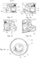
- Fig. 11 shows the spring plate 42 in the straight shaft 1. It is shown that the ball 44 of the spring plate 42 is inserted into an elongated receiving groove 48 in the pinion 18.
- the receiving groove 48 runs in the longitudinal direction of the shaft 1 and the ball 44 is positively connected to the receiving groove 48.
- the ball 44 therefore moves with the rotation of the pinion 18 and also moves in the longitudinal direction of the receiving groove 48.
- the side of the spring plate 42 that is opposite the ball 44 is fastened to the adjustment bushing 28. A rotation of the pinion 18 is thus transferred from the spring plate 42 to the adjustment bushing 28.
- the adjustment bushing 28 rotates with the spring plate 42.
- the spring plate 42 is connected to the adjustment bushing 28, for example by welding or gluing.
- the receiving groove 48 can also be prepared in the adjustment bushing 28.
- the ball 44 is connected to the adjustment bushing 28 and the spring plate 42 is welded or glued to the pinion 18.
- the ball 44 moves in a spherical receiving groove 48 in the pinion 18 in the longitudinal direction of the receiving groove 48.
- Distal fixation in the adjustment bushing 28 is achieved by means of gluing or welding. Proximal fixation is omitted.
- the positive locking of the ball 44 in the receiving groove 48 transmits the rotary movement via the spring plate 42 to the adjusting bush 28.
- Fig. 12 shows the spring plate 42 in the shaft 1 angled by 45°.
- the pinion 18 is rotated by 180° around its longitudinal axis compared to the straight shaft 1.
- the receiving groove 48 with the ball 44 is of course also rotated by 180°.
- the adjustment bushing 28 is also rotated by the spring plate 42.
- the driving pin 30 takes the distal shaft tip 32 with it, which also rotates by 180°. It is clear that the spring plate 42 has a greater distance from the flexible milling cutter 10 in the angled state than in the extended state.
- Fig. 13 shows a top view of the spring plate 42.
- the shaft 1 is angled by 22.5°.
- the rotation of the pinion 18 causes the spring plate 42 to rotate and the adjustment bushing 28 to rotate as well. This causes the spring plate 42 to twist.
- the ball 44 moves in the longitudinal direction of the receiving groove 48 when the pinion 18 rotates in the receiving groove 48.
- Fig. 14 shows the spring plate 42. It is clear that the spring plate 42 is twisted about its own longitudinal axis during rotation or the transmission of the rotary motion from the pinion 18 to the adjusting bushing 28. In the 22.5° position it is clear that the spring plate 42 is twisted towards the receiving groove 48 and is also twisted about its longitudinal axis. A corresponding flexibility of the spring plate 42 is a basic requirement for the function.
- Fig. 15 shows a cross-section through the proximal shaft section 2 with the eccentric locking bush 22 and the pinion 18.
- the ball 44 is positively inserted into the receiving groove 48 and follows the rotation of the receiving groove 48.
- the special spherical receiving groove 48 ensures that the ball 44 of the spring plate 42 is held in place by a positive fit and thus has to follow the rotational movement of the pinion 18.
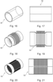
- Fig. 16 shows the silicone hose 34 according to the first embodiment.
- the silicone hose 34 is one way of realizing the flexible transmission element.
- the silicone hose 34 is glued at one end to the pinion 18 and the adjustment bushing 28.
- Fig. 17 shows a side view of the silicone hose 34.
- Fig. 18 shows a flexible transmission element according to a third embodiment.
- the transmission element is a flexible metal bellows 50.
- the metal bellows 50 is essentially a hollow, elongated metal tube. In the middle, the metal tube has folds that resemble the folds of a bellows or an accordion. The folds make the metal bellows 50 bendable or flexible.
- the metal bellows 50 can be attached to the pinion 18 and the adjustment bushing 28 by gluing or welding.
- Fig. 19 shows a side view of the metal bellows 50.
- Fig. 20 shows a flexible transmission element according to a fourth embodiment.
- the transmission element is a flexible metal tube 52.
- the metal tube 52 is essentially a thin, elongated metal tube.
- the metal tube 52 has slots/recesses that run in the radial direction of the metal tube 52. That is, the metal tube 52 has a gap geometry. The recesses make the metal tube 52 flexible.
- the metal tube 52 can be attached to the pinion 18 and the adjustment bushing 28 by gluing or welding.
- Fig. 21 shows a side view of the metal tube 52.
- Fig. 22 shows an extended shaft 1 according to a fifth embodiment.
- the roller bearing 26 is not a full ball bearing, but only has three or more balls 38.
- the receiving pin 25 of the outer tube 12 has three ball holes 54.
- the distal shaft tip 32 has a circumferential groove 56.
- the balls 38 are each inserted into the corresponding ball hole 54 through the filling opening 40.
- the closure is analogous to the first embodiment.
- the balls 38 rotate in their respective ball hole 54. This leads to slightly higher friction, since the rolling movement is only possible on the groove 56 of the distal shaft tip 32. However, significantly fewer balls 38 are required and assembly is faster.
- Fig. 23 shows a cross section through the distal shaft section 4 and the rolling bearing 26.
- the ball bores 54 are equally spaced in the circumferential direction.
- Fig. 24 shows an extended shaft 1 according to a sixth embodiment.
- the distal shaft tip 32 is fixed to the outer tube 12 by a rear locking mechanism 58.
- the distal shaft tip 32 In order to be able to implement the rear locking mechanism 58, the distal shaft tip 32 must be made of a flexible material, such as plastic.
- the distal shaft tip 32 is bent open for assembly and locked into the projections of the outer tube 12.
- the rotation is transmitted by a lateral driving pin 60, since space has been created by the missing balls.
- the driving pin 60 protrudes from the adjustment bushing 28 and rotates with the adjustment bushing 28.
- the outer tube 12 has a recess 61 in which the driving pin 60 is movable.
- the driving pin 60 runs through the recess 61 and is positively connected to a bulge of the distal shaft tip 32.
- Fig. 25 shows a cross section through the distal shaft tip 32.
- the adjustment bushing 28 has the protruding driving pin 60, which engages in the distal shaft tip 32.
- the driving pin 60 penetrates the outer tube 12 through the recess 61.
- the recess 61 encompasses half the circumference of the outer tube 12.
- the driving pin 60 transfers the rotation of the adjustment bushing 28 to the distal shaft tip 32.
- Fig. 26 shows an angled shaft 1 according to a seventh embodiment.
- the shaft 1 does not have a milling cutter, but has jaw parts or scissor blades 62 that protrude from the distal shaft section. A user can use the jaw parts 62 to grip or fix objects.
- a maximum angle of 90 degrees can be achieved by cutting at an angle of 45 degrees (instead of 22.5 degrees) (not shown).
- the more elliptical shape of the cutting surface increases the lateral overhang of the shaft edges in the area of the swivel joint (particularly in the intermediate position at half the adjustment range).
- the overhang can be reduced by using special curves.
- angle head enables particularly rigid instruments that can maintain their position even under high loads.
- the flexible cutter 10 can have a special section for the bending area, which on the one hand can withstand the movement of the instrument tip and on the other hand can transmit the torque.
- This can be, for example, a thin wire, braided strands or a universal joint or the like.
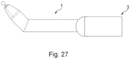
- Fig. 27 shows the shaft 1 with a medical hand instrument 3.
- the shafts of all embodiments are suitable for the medical hand instrument 3 and can be connected to the medical hand instrument 3.
Landscapes
- Health & Medical Sciences (AREA)
- Life Sciences & Earth Sciences (AREA)
- Surgery (AREA)
- Engineering & Computer Science (AREA)
- Heart & Thoracic Surgery (AREA)
- Medical Informatics (AREA)
- Nuclear Medicine, Radiotherapy & Molecular Imaging (AREA)
- Veterinary Medicine (AREA)
- Public Health (AREA)
- General Health & Medical Sciences (AREA)
- Animal Behavior & Ethology (AREA)
- Biomedical Technology (AREA)
- Molecular Biology (AREA)
- Physics & Mathematics (AREA)
- Biophysics (AREA)
- Radiology & Medical Imaging (AREA)
- Pathology (AREA)
- Optics & Photonics (AREA)
- Orthopedic Medicine & Surgery (AREA)
- Mechanical Engineering (AREA)
- Dentistry (AREA)
- Oral & Maxillofacial Surgery (AREA)
- Ophthalmology & Optometry (AREA)
- Flexible Shafts (AREA)
- Surgical Instruments (AREA)
Description
- Die vorliegende Offenbarung betrifft einen Schaft eines oder für ein medizinisches Handinstrument.
- In der Operationstechnik ist es vorteilhaft, den distalen Schaftabschnitt eines Schafts von einem medizinischen Handinstrument abzuwinkeln. Dadurch können Operationen in geringem Raum durchgeführt werden, beispielsweise bei Operationen an der Wirbelsäule.
- Aus dem Bereich der Operationsroboter sind schon seit längerem Instrumente bekannt, die eine Abwinklung der distalen Spitze ermöglichen. Dadurch wird eine präzise Bewegung der Instrumente auf engstem Raum ermöglicht. Allerdings werden bei diesen Instrumenten keine rotierenden Werkzeuge abgewinkelt. Ein Beispiel hierfür ist der Operationsroboter "Da Vinci" von der Firma Intuitive Surgical.
- Es sind verschiedene abwinkelbare medizinische Geräte auf dem Markt erhältlich. So hat die Firma Human Xtensions eine abwinkelbare Zange entwickelt. Ein Operateur kann handgehaltene robotische Instrumente nutzen, um "grobe" Handbewegungen in feinfühlige Bewegungen an der Instrumentenspitze zu übersetzen. Eine Instrumentenspitze kann bei diesem Instrument über einen flexiblen Bereich, welcher sich über eine Länge von ca. 20 mm erstreckt, abgewinkelt werden. Der flexible Bereich wird durch eine Art Kunststoff-Stent gestützt. Die Verstellung erfolgt mittels außen am Stent vorbei geführter Drahtlitzen. Nachteilig ist hier die Länge des Biegebereichs, sowie die sehr nachgiebige Spitze. Die Nachgiebigkeit ist hierbei durch den Kunststoff-Stent und die Drahtlitzen bedingt.
- Weiterhin gibt es bereits Hersteller von winkelbaren Fräs-Handstücken/ medizinischen Handinstrumenten. Diese werden vorwiegend bei endoskopischen Eingriffen an der Wirbelsäule eingesetzt und ermöglichen minimal-invasive Techniken, sowie die einfache Bearbeitung schwer zugänglicher Strukturen in diesem Bereich. Die Gelenkkonstruktionen dieser Fräs-Handstücke weisen eine eher offene Bauform auf und besitzen eine gewisse Flexibilität der Winkelung. D.h. bei Druck auf die Fräserspitze wird der Winkel leicht verändert. Weiterhin sind bei diesen Fräs-Handstücken nur Abwinkelungen von bis zu 36° möglich. Ein Beispiel hierfür sind Fräs-Handstücke der Firma Joimax.
- Es existieren winkelbare Akkuschrauber mit einer schrägen Ebene. Im Bereich der Heimwerker-Geräte gibt es Akkuschrauber mit winkelbarem Kopf. Diese weisen ein ähnliches Drehgelenk wie die nachfolgend beschriebene Offenbarung auf und besitzen eine sehr gute Kraftaufnahme der Winkelung (starres Gelenk). Je nach Winkelung der Drehebene sind hier Abwinkelungen von bis zur 90° möglich. Jedoch müssen die Akkuschrauber von außen verstellt werden. Sie verfügen somit nicht über die interne Ansteuerung.
- Ferner existieren Highspeed Fräshandstücke/ medizinische Handinstrumente mit gewinkeltem Schaft. Dank wechselbarer Schäfte kann ein Handstück zwischen drei Varianten gewählt werden: 0°-, 7,5°- und 15°-Abwinkelung. Größter Nachteil ist dabei der große Biegeradius, über den die Abwinkelung realisiert wird. Dieser verbraucht sehr viel Platz und beschränkt die Aktionsmöglichkeiten im OP-Feld. Außerdem ist der Winkel nicht intraoperativ verstellbar. Durch die fixe Winkelung ist kein endoskopisches Arbeiten mit den gewinkelten Schäften möglich, da sie sich nicht in den geraden Arbeitskanal des Endoskops einschieben lassen. Weiterhin ist die maximale Abwinkelung mit 15° nicht besonders groß.
- Aus den Offenbarungen
DE 10 2017 010 033 A1 undUS 10 178 998 B2 - Aus der
DE 103 92 849 T5 ist ein Fräser mit einem distalen und einem proximalen Schaftabschnitt bekannt, die jeweils derart zueinander verdrehbar sind, dass die beiden Schaftabschnitte durch ihre angestellten Stirnseiten zueinander abgewinkelbar sind. Die beiden Schaftabschnitte werden dabei durch ein Kegelradgetriebe gegeneinander abgewinkelt. - Die
RU 2 181 566 C2 - Die
US 6 050 989 A zeigt ein chirurgisches Handstück mit einer abwinkelbaren distalen Buche. Die distale Buchse ist relativ zu einer proximalen Buchse rotierbar, wobei die distale und die proximale Buchse über ein federvorgespanntes Verbindungselement miteinander verbunden sind.US 5 575 799 A zeigt ferner ein chirurgisches Handstück mit einer abwinkelbaren distalen Spitze. Die distale Spitze ist dabei durch eine Kegelraderzahnung gegenüber einem proximalen Schaftabschnitt rotierbar und durch angestellte Stirnseiten abwinkelbar. - Aus der
WO 99 / 21 686 A1 - Die Aufgabe der Offenbarung besteht deshalb darin, die Nachteile des Stands der Technik zu überwinden und einen Schaft für ein medizinisches Handinstrument bereitzustellen, bei dem ein distaler Schaftabschnitt im Betrieb abgewinkelt werden kann und sich der Winkel zwischen dem distalen Schaftabschnitt und einem proximalen Schaftabschnitt auch unter Belastung nicht ändert. Insbesondere soll der Schaft des Handinstruments durch einen einfachen und fehlerresistenten Mechanismus abwinkelbar sein.
- Diese Aufgabe wird offenbarungsgemäß durch einen Schaft für ein medizinisches Handinstrument mit den Merkmalen des Anspruchs 1 gelöst. Vorteilhafte Weiterbildungen der Offenbarung sind Gegenstand der beigefügten Unteransprüche.
- Die Offenbarung betrifft demzufolge einen Schaft für ein medizinisches Handinstrument mit einem distalen Schaftabschnitt und einem proximalen Schaftabschnitt, deren jeweils einander zugewandte Stirnseiten, von denen zumindest eine mit einem Anstellwinkel ungleich 90° bezüglich der jeweiligen Schaftlängsachse angestellt ist, sodass sich je nach Relativdrehposition der beiden Schaftabschnitte unterschiedliche Schaftformen ergeben. Das Ritzel ist durch ein flexibles Übertragungselement mit der Verstellbuchse in dem distalen Schaftabschnitt rotationsübertragend verbunden.
- Das flexible Übertragungselement kann dabei vorzugsweise eine Drehwelle oder ein Blech(-streifen) sein, das sich sowohl konzentrisch oder auch eiernd (d.h. auf einer Umlaufbahn) um eine Längsachse dreht. Das Ritzel ist mit dem flexiblen Übertragungselement verbunden. Die Verbindung kann beispielsweise durch Schweißen und/oder Kleben oder eine andere lösbare oder nicht lösbare Fügetechnik realisiert sein. Auf der dem Ritzel abgewandten Seite des flexiblen Übertragungselements kann bevorzugt die Verstellbuchse angebracht sein. Auch diese Verbindung kann durch Schweißen oder Kleben realisiert sein. Das flexible Übertragungselement übertragt die Rotation/ Drehung des Ritzels auf die Verstellbuchse.
- In anderen Worten hat der Schaft einen abwinkelbaren distalen Schaftabschnitt. Der distale Schaftabschnitt und der proximale Schaftabschnitt weisen beide jeweils ein schräges Ende/ eine bezüglich der jeweiligen Schaftabschnittsachse angestellte Stirnseite auf. D.h. jeweils ein Ende/ Endabschnitt/ Stirnseite des distalen und proximalen Schaftabschnitts ist nicht gerade, sondern abgeschrägt/ angestellt. Die Schrägungen/ angestellten Endabschnitte/ Stirnseiten haben jeweils den im Wesentlichen gleichen Anstellwinkel. Darum passen die Schrägungen derart zueinander, dass der proximale und der distale Schaftabschnitt in einer bestimmten Relativdrehposition einen geraden Schaft/ ein gerades Rohr bilden. Wenn nun der distale Schaftabschnitt um seine Längsachse relativ zum proximalen Schaftabschnitt rotiert und der proximale Schaftabschnitt stehen bleibt, wird der distale Schaftabschnitt durch die angestellten Stirnseiten/ Endabschnitte zwangsläufig abgewinkelt.
- Die vorstehend beschriebene Lösung weist folgende Vorteile auf:
- Der distale Schaftabschnitt des Schafts kann stufenlos verstellt werden.
- Die Ansteuerung der Drehmechanik ist dabei vollständig in den Schaft integriert und lässt sich über eine nicht näher beschriebene Drehhülse am proximalen Endabschnitt des Schaftes verstellen.
- Das speziell aufgebaute Drehgelenk ist sehr stabil, leichtgängig und vollkommen unempfindlich gegenüber äußeren Biegekräften. Dadurch wird eine sehr genaue Position des distalen Schaftabschnitts ermöglicht, die sich auch nicht durch auftretende Fräskräfte verändert. Dies ist ein entscheidender Vorteil bei der Anwendung von robotergesteuerten Techniken.
- Eine hohe Präzision und ein geringes Fehlerrisiko sind hier die wichtigsten Argumente.
- Der distale Schaftabschnitt des medizinischen Handinstruments ist im Betrieb abwinkelbar. Das heißt es ist möglich, den distalen Schaftabschnitt während einer Operation abzuknicken. Dadurch, dass der distale Schaftabschnitt auf der Schrägung/ angestellten Stirnseite des proximalen Schaftabschnitts aufliegt, ist der distale Schaftabschnitt fest gelagert.
- Das medizinische Handinstrument weist bevorzugt ein Einstellrad, den (angestellten) proximalen Schaftabschnitt, den relativ dazu abwinkelbaren distalen Schaftabschnitt, einen flexiblen Fräser und ein Lager auf. Der proximale Schaftabschnitt weist ein feststehendes Außenrohr, ein Hohlrad (mit einer Innenverzahnung), eine exzentrische Sicherungsbuchse und ein Ritzel (mit einer Außenverzahnung, die mit der Innenverzahnung des Hohlrads kämmt), das mit dem Hohlrad in Kämmeingriff steht, auf. Der relativ abwinkelbare distale Schaftabschnitt weist weiter bevorzugt ein flexibles Übertragungselement, eine Verstellbuchse mit einem Mitnahmezapfen und eine distale Schaftspitze auf. Der distale Schaftabschnitt ist vorzugsweise mit dem Lager auf dem proximalen Abschnitt gelagert. Der flexible Fräser ist vorzugsweise durch den proximalen Schaftabschnitt und den distalen Schaftabschnitt geführt und ist zusammen mit dem distalen Schaftabschnitt abwinkelbar. Die Verstellbuchse ist vorzugsweise durch das flexible Übertragungselement mit dem Ritzel derart verbunden, dass eine Rotationsbewegung des Ritzels auf die Verstellbuchse übertragen wird. Die Verstellbuchse überträgt vorzugsweise die Drehung durch den Mitnahmezapfen auf die distale Schaftspitze. Durch die Drehung des distalen Schaftabschnitts relativ zum angestellten proximalen Schaftabschnitt wird der distale Schaftabschnitt abgewinkelt.
- Gemäß einem weiteren bevorzugten Merkmal der Offenbarung weist der proximale Schaftabschnitt das Hohlrad mit der Innenverzahnung auf, die mit der Außenverzahnung des Ritzels kämmt. Der proximale Schaftabschnitt weist bevorzugt das feststehende Außenrohr mit der angestellten Stirnseite auf. In dem feststehenden Außenrohr ist das Hohlrad um seine Längsachse drehbar gelagert. Das Hohlrad ist bevorzugt vom proximalen Endabschnitt des Schaftes aus bedienbar und weist die Innenverzahnung auf. Die Innenverzahnung kämmt mit der Außenverzahnung des Ritzels. In anderen Worten ausgedrückt ist die Innenverzahnung in operativem Eingriff mit der Außenverzahnung. Dadurch wird eine Rotation des Hohlrads auf das Ritzel übertragen.
- Gemäß einem weiteren bevorzugten Merkmal der Offenbarung hat die Verstellbuchse den Mitnahmezapfen, der formschlüssig mit der distalen Schaftspitze verbunden ist und die Rotation der Verstellbuchse auf die distale Schaftspitze überträgt. Die Verstellbuchse ist bevorzugt mit der distalen Schaftspitze durch den Mitnahmezapfen verbunden. Die Rotation der Verstellbuchse wird dadurch auf die distale Schaftspitze übertragen und die distale Schaftspitze gedreht. Im Endeffekt wird die distale Schaftspitze also bevorzugt mit dem Hohlrad mitgedreht. Durch die Drehung der distalen Schaftspitze stellen sich die angestellten Stirnseiten des distalen Schaftabschnitts und des proximalen Schaftabschnitts derart gegeneinander, dass der distale Schaftabschnitt abgewinkelt wird.
- Gemäß einem weiteren bevorzugten Merkmal der Offenbarung weist der proximale Schaftabschnitt eine exzentrische Sicherungsbuchse auf. Die exzentrische Sicherungsbuchse ist vorzugsweise in dem Außenrohr angebracht. Durch die exzentrische Sicherungsbuchse wird das Ritzel an eine Seite des Außenrohrs gedrückt, die der exzentrischen Sicherungsbuchse gegenüberliegt. Das Ritzel ist bevorzugt an der Seite des Schafts, in die der distale Schaftabschnitt nicht abgewinkelt wird. Das Ritzel wird durch das Hohlrad angetrieben und dreht sich in der exzentrischen Sicherungsbuchse. Dadurch ist das Ritzel immer an der Seite des Außenrohrs angeordnet. Da das Ritzel bevorzugt an der Seite angeordnet ist, in die sich der distale Schaftabschnitt nicht biegt, ist das flexible Übertragungselement weiter vom flexiblen Fräser entfernt.
- Gemäß einem weiteren bevorzugten Merkmal der Offenbarung ist das flexible Übertragungselement ein flexibles Federblech vorzugsweise mit einer seitlich angebrachten Kugel. Das flexible Übertragungselement kann als ein eierndes/auf einer Kreisbahn umlaufendes Blech ausgeführt sein. Wenn das Federblech mit dem Ritzel rotiert, rotiert es nicht um seine eigene Längsachse, sondern eiert um eine Längsachse des Ritzels. Dadurch ist das Federblech in der um 45° abgewinkelten Stellung am weitesten vom flexiblen Fräser entfernt. Dadurch ist das Risiko einer Kollision minimiert und der Aufbau des Schafts kann kleiner ausgeführt werden.
- Gemäß einem weiteren bevorzugten Merkmal der Offenbarung ist die Kugel des flexiblen Federblechs in einer kugelförmigen Aufnahmenut in dem Ritzel aufgenommen und die der Kugel gegenüberliegende Seite des Federblechs ist bevorzugt mit der Verstellbuchse verbunden.
- Gemäß einem weiteren bevorzugten Merkmal der Offenbarung ist die Kugel des flexiblen Federblechs in einer kugelförmigen Aufnahmenut in dem Ritzel aufgenommen ist und die der Kugel gegenüberliegende Seite des flexiblen Federblechs ist vorzugsweise mit dem Ritzel verbunden.
- Die Kugel ist bevorzugt bewegbar in der Aufnahmenut aufgenommen. Die Kugel ist bevorzugt formschlüssig in der Aufnahmenut befestigt. Dabei kann die Kugel sich aber in eine Längsrichtung der Aufnahmenut bewegen. Die Aufnahmenut kann in dem Ritzel oder in der Verstellbuchse angebracht sein. Auf der Seite des Federblechs, die der Kugel gegenüberliegt ist das Federblech mit dem entsprechenden Bauteil vorzugsweise verschweißt oder verklebt.
- Gemäß einem weiteren bevorzugten Merkmal der Offenbarung ist das flexible Übertragungselement ein Silikonschlauch. Vorzugsweise ist der Silikonschlauch ebenfalls mit der Verstellbuchse und dem Ritzel verbunden. Der Silikonschlauch wird vorzugsweise durch Kleben an der Verstellbuchse und dem Ritzel befestigt.
- Gemäß einem weiteren bevorzugten Merkmal der Offenbarung ist das flexible Übertragungselement ein flexibler Metallfaltenbalg. Der flexible Metallfaltenbalg hat Falten, die den Falten einer Ziehharmonika oder eines Blasebalgs ähneln. Dadurch ist der Metallfaltenbalg flexibel und dehnbar.
- Gemäß einem weiteren bevorzugten Merkmal der Offenbarung ist das flexible Übertragungselement ein flexibles Metallrohr. Das Metallrohr hat vorzugsweise Aussparungen bzw. eine Spaltgeometrie, die das Metallrohr flexibel machen.
- Beide Lösungen mit Metallrohren als Basis haben folgende Vorteile:
- Die Metallrohre sind sehr torsionssteif bei gleichzeitiger guter Biegbarkeit. Dadurch ist eine sehr präzise Verstellung bzw. stabile Position des distalen Schaftabschnitts möglich.
- Bei der Spaltgeometrie wird die Torsionsteifigkeit durch die spezielle Anordnung der Spalte erreicht.
- In Drehrichtung gibt es keine Unterbrechung der Kontur und dadurch kein Umkehrspiel.
- Beide Lösungen mit Metallrohren als Basis können mit der Verstellbuchse bzw. dem Ritzel verschweißt oder geklebt werden.
- Gemäß einem weiteren, bevorzugten Merkmal der Offenbarung ist ein Abknickwinkel zwischen dem proximalen Schaftabschnitt und dem distalen Schaftabschnitt doppelt so groß, wie der Anstellwinkel der angestellten Stirnseiten. Im abgewinkelten Zustand liegen die angestellten Stirnseiten derart aneinander an, dass sich die Anstellwinkel addieren. Da beide Stirnseiten den gleichen Anstellwinkel haben, ist der Abknickwinkel doppelt so groß, wie der Anstellwinkel. Durch die Verdopplung ergeben sich große Abknickwinkel, ohne große Anstellwinkel zu fordern.
- Gemäß einem weiteren bevorzugten Merkmal der Offenbarung hat der Abknickwinkel zwischen dem proximalen Schaftabschnitt und dem distalen Schaftabschnitt ein Maximum und der Anstellwinkel wird bei einer weiteren Rotation des distalen Schaftabschnitts wieder kleiner. Wenn der distale Schaftabschnitt weiter rotiert wird, stehen die angestellten Stirnseiten nicht mehr direkt aufeinander. Deshalb nimmt der Abknickwinkel bei einer weiteren Rotation wieder ab.
- Gemäß einem weiteren bevorzugten Merkmal der Offenbarung ist die Verstellbuchse aus einem Gleitlagerwerkstoff, vorzugsweise PTFE oder POM, gefertigt und/oder weist eine Beschichtung mit PTFE auf. Die Verstellbuchse rotiert bevorzugt in einer Aufnahmebohrung des Außenrohrs. Vorzugsweise ist in der Aufnahmebohrung kein weiteres Lager angeordnet. Deshalb muss die Verstellbuchse gleiten. Durch die Fertigung aus dem Gleitlagerwerkstoff hat die Verstellbuchse eine kleinere Reibung bezüglich der Aufnahmebohrung.
- Gemäß einem weiteren bevorzugten Merkmal der Offenbarung ist die distale Schaftspitze aus einem Kunststoff mit guten Gleiteigenschaften, vorzugsweise PTFE oder POM, gefertigt. Wenn zwischen dem Außenrohr und der distalen Schaftspitze kein Lager angebracht ist, muss die distale Schaftspitze bezüglich dem Außenrohr drehbar sein. Das wird durch Materialauswahl der distalen Schaftspitze sichergestellt.
- Gemäß einem weiteren bevorzugten Merkmal der Offenbarung ist die distale Schaftspitze aus einem flexiblen Kunststoff gefertigt. Die distale Schaftspitze ist derart gefertigt, dass sie biegbar ist. Damit kann die distale Schaftspitze mit dem Außenrohr eine Hinterrastung/Hinterschneidung bilden, die die distale Schaftspitze an dem proximalen Schaftabschnitt fixiert. Für die Montage wird die distale Schaftspitze aufgebogen und mit dem Außenrohr verrastet.
- Gemäß einem weiteren bevorzugten Merkmal der Offenbarung wird über das Einstellrad manuell oder motorisch eine gewünschte Winkelstellung eingestellt. Das Einstellrad befindet sich vorzugsweise am proximalen Ende des Handinstruments. Damit kann ein Benutzer einen Wunschwinkel einstellen. Der Benutzer kann beispielsweise an einem Rädchen drehen, das das Einstellelement darstellt, oder der Benutzer kann den Wunschwinkel an einem Hebel, Joystick oder Ähnliches einstellen.
- Gemäß einem weiteren bevorzugten Merkmal der Offenbarung ist das Lager ein Vollkugellager. Durch ein Vollkugellager wird die Reibung in dem Lager verringert. Dadurch gibt es weniger Verluste beim Einstellen des Winkels. Ebenso kann dadurch das notwendige Spiel für eine leichtgängige Verstellbarkeit minimiert werden und somit die Präzision der distalen Spitze erhöht werden.
- Gemäß einem weiteren bevorzugten Merkmal der Offenbarung ist das Wälzlager ein Kugellager mit mindestens, vorzugsweise genau drei Kugeln. Durch die Verwendung von drei oder auch mehreren Kugeln erhöht sich die Reibung im Wälzlager. Vorteilhaft ist aber, dass die Montage des Wälzlagers schneller geht, da weniger Kugeln eingefüllt werden müssen und, dass das Wälzlager kostengünstiger ist.
-
-
Fig. 1 zeigt einen Schaft gemäß einer ersten Ausführungsform in einer geraden Schaftform; -
Fig. 2 zeigt den Schaft gemäß der ersten Ausführungsform bei dem ein distaler Schaftabschnitt im Vergleich zu einem proximalen Schaftabschnitt um 22,5° abgewinkelt ist; -
Fig. 3 zeigt den Schaft gemäß der ersten Ausführungsform bei dem der distale Schaftabschnitt im Vergleich zu dem proximalen Schaftabschnitt um 45° abgewinkelt ist; -
Fig. 4 zeigt einen Längsschnitt durch den geraden Schaft; -
Fig. 5 zeigt einen Längsschnitt durch den um 22,5° abgewinkelten Schaft; -
Fig. 6 zeigt einen Längsschnitt durch den um 45° abgewinkelten Schaft; -
Fig. 7 zeigt einen Querschnitt durch den proximalen Schaftabschnitt; -
Fig. 8 zeigt einen Querschnitt durch ein Wälzlager, das zwischen dem proximalen Schaftabschnitt und dem distalen Schaftabschnitt angeordnet ist; -
Fig. 9 zeigt eine isometrische Ansicht eines Federblechs mit einer Kugel; -
Fig. 10 zeigt eine Seitenansicht des Federblechs; -
Fig. 11 zeigt das Federblech in dem geraden Schaft; -
Fig. 12 zeigt das Federblech in dem um 45° abgewinkelten Schaft; -
Fig. 13 zeigt eine Draufsicht auf das Federblech in dem um 22,5° abgewinkelten Schaft; -
Fig. 14 zeigt das tordierte Federblech in dem um 22,5° abgewinkelten Schaft; -
Fig. 15 zeigt einen Querschnitt durch den proximalen Schaftabschnitt; -
Fig. 16 zeigt eine isometrische Ansicht eines flexiblen Silikonschlauchs gemäß der ersten Ausführungsform; -
Fig. 17 zeigt eine Seitenansicht des flexiblen Silikonschlauchs gemäß der ersten Ausführungsform; -
Fig. 18 zeigt eine isometrische Ansicht eines flexiblen Metallfaltenbalgs gemäß einer dritten Ausführungsform; -
Fig. 19 zeigt eine Seitenansicht des flexiblen Metallfaltenbalgs gemäß der dritten Ausführungsform; -
Fig. 20 zeigt eine isometrische Ansicht eines flexiblen Metallrohrs gemäß einer vierten Ausführungsform; -
Fig. 21 zeigt eine Seitenansicht des flexiblen Metallrohrs gemäß der vierten Ausführungsform; -
Fig. 22 zeigt einen Längsschnitt durch den geraden Schaft mit einem Wälzlager gemäß einer fünften Ausführungsform; -
Fig. 23 zeigt einen Querschnitt durch das Wälzlager gemäß der fünften Ausführungsform; -
Fig. 24 zeigt einen Längsschnitt durch einen geraden Schaft gemäß einer sechsten Ausführungsform; -
Fig. 25 zeigt einen Querschnitt durch einen distalen Schaftabschnitt gemäß der sechsten Ausführungsform; -
Fig. 26 zeigt einen Schaft gemäß einer siebten Ausführungsform; und -
Fig. 27 zeigt ein Handinstrument mit dem offenbarungsgemäßen abwinkelbaren Schaft. - Nachstehend werden bevorzugte Ausführungsformen der vorliegenden Offenbarung auf der Basis der zugehörigen Figuren beschrieben.
-
Fig. 1 zeigt einen Schaft 1 eines oder für ein medizinisches Handinstrument in einer geraden Schaftform. D.h. ein proximaler Schaftabschnitt 2 des Schafts 1 und ein distaler Schaftabschnitt 4 des Schafts 1 sind in einer Linie angeordnet bzw. weisen einen Winkel von 0° zueinander auf. Der proximale Schaftabschnitt 2 ist dabei im Wesentlichen rohrförmig und weißt an seinem distalen Endabschnitt eine in Schaftlängsachse angestellte Stirnseite 6 auf. Der distale Schaftabschnitt 4 ist ebenfalls annähernd rohrförmig. Das Rohr läuft zum distalen Ende zu einer Spitze zusammen. Der distale Schaftabschnitt 4 weist an seinem proximalen Endabschnitt eine in Schaftlängsachse angestellte Stirnseite 8 auf. Ein flexibler Fräser 10 ragt am distalen Ende aus dem Schaft 1. Der flexible Fräser 10 verläuft entlang der Schaftlängsachse. Es ist offensichtlich, dass statt dem flexiblen Fräser 10 ein Bohrer oder ein sonstiges medizinisches Werkzeug aus dem Schaft 1 ragen kann. - Die angestellten Stirnseiten 6, 8 weisen jeweils einen Anstellwinkel von vorzugsweise 22,5° zu einer Normalenebene zur Schaftlängsachse auf. Wenn der Schaft 1 in einer geraden Schaftform bzw. ausgestreckt ist, sind die beiden angestellten Stirnseiten 6, 8 derart zueinander versetzt, dass sich die langen Enden der angestellten Stirnseiten 6, 8 in Relation zur Längsachse gegenüberliegen. Die angestellten Stirnseiten liegen aufeinander auf. Die angestellten Stirnseiten müssen nicht zwangsläufig einen Anstellwinkel von 22,5° aufweisen. Es sind auch Anstellwinkel von beispielsweise 10°, 18°, 30°, 45° oder jeder andere Anstellwinkel möglich.
-
Fig. 2 zeigt den Schaft 1, wobei der distale Schaftabschnitt 4 zu dem proximalen Schaftabschnitt 2 um 22,5° abgewinkelt ist. Der distale Schaftabschnitt 4 ist im Vergleich zur Stellung inFig. 1 um 90° um die eigene Längsachse relativ zum proximalen Schaftabschnitt 2 gedreht. Dabei liegen die angestellten Stirnseiten 6,8 nicht vollständig / flächig aufeinander auf. Die angestellte Stirnseite 8 ist mit dem distalen Schaftabschnitt 4 um 90° relativ zur angestellten Stirnseite 6 des proximalen Schaftabschnitts 2 gedreht, somit steht ein langes Ende der angestellten Stirnseite 8 über die angestellte Stirnseite 6 hinaus. Durch den Anstellwinkel der angestellten Stirnseite 6 steht der distale Schaftabschnitt 4 relativ zum proximalen Schaftabschnitt 2 nach oben. Der flexible Fräser 10 wird mit dem distalen Schaftabschnitt 4 zusammen abgewinkelt. -
Fig. 3 zeigt den Schaft 1, wobei der distale Schaftabschnitt 4 zu dem proximalen Schaftabschnitt 2 bei einem jeweiligen Anstellwinkel der beiden Stirnseiten um 22,5° folglich um 45° abgewinkelt ist. Der distale Schaftabschnitt 4 ist im Vergleich zur Stellung inFig. 1 um 180° um die eigene Längsachse gedreht. Die angestellten Stirnseiten 6, 8 liegen in dieser Stellung wieder komplett / flächig aufeinander auf. Durch die Drehung des distalen Schaftabschnitts 4 sind die langen Enden der angestellten Stirnseiten 6, 8 aber nebeneinander positioniert. Die Anstellwinkel der angestellten Stirnseiten 6, 8 addieren sich somit. Dadurch wird der distale Schaftabschnitt 4 im Vergleich zum proximalen Schaftabschnitt 2 um den doppelten Anstellwinkel der angestellten Stirnseiten 6, 8 abgewinkelt. -
Fig. 4 zeigt einen Querschnitt des ausgestreckten (geraden) Schafts 1 durch eine Längsachse. Der proximale Schaftabschnitt 2 weist ein feststehendes Außenrohr 12, ein Hohlrad 14 mit einer Innenverzahnung 16, ein Ritzel 18 mit einer Außenverzahnung 20 und eine exzentrische Sicherungsbuchse 22 auf. Das Hohlrad 14 ist innerhalb des Außenrohrs 12 positioniert und die Längsachse des Außenrohrs 12 entspricht der Längsachse des Hohlrads 14. Das Außenrohr 12 und das Hohlrad 14 sind also konzentrisch angeordnet. Das Hohlrad 14 ist mit einem proximalen Einstellrad (nicht dargestellt) verbunden und dreht sich mit dem Einstellrad mit. An dem Einstellrad kann ein Nutzer eine gewünschte Winkelstellung einstellen. Die Winkelstellung kann entweder manuell oder durch einen Motor unterstützt eingestellt werden. Ebenso kann das proximale Einstellrad eine Arretierung (nicht dargestellt) (beispielsweise ein Kugeldruckstück, eine Klemmschraube oder ein Rastring) aufweisen, welche die Verstellung des distalen Schaftabschnitts 4 blockiert. So wird sichergestellt, dass die Verstellung nur durch aktives, beabsichtigtes Handeln erfolgt. Das Außenrohr 12 bewegt sich nicht. Das distale Ende des Außenrohrs 12 weist die angestellte Stirnseite 6 auf. Das distale Ende des Außenrohrs 12 weist weiterhin eine Aufnahmebohrung 24 und einen Aufnahmezapfen für ein Wälzlager 26 auf. Das Außenrohr weist eine Rille/ Nut für die Kugeln des Wälzlagers 26 auf. Auf dem Wälzlager 26 ist der distale Schaftabschnitt 4 gelagert. - Die Innenverzahnung 16 kämmt mit der Außenverzahnung 20 des Ritzels 18. Dadurch wird eine Rotation des Hohlrads 14, die durch das Einstellrad gesteuert wird, auf das Ritzel 18 übertragen. Die Drehrichtung des Ritzels 18 ist dabei entgegengesetzt der Drehrichtung des Hohlrads 14. Das Ritzel 18 wird vom Hohlrad 14 angetrieben, das Ritzel dreht sich aber in der exzentrischen Sicherungsbuchse 22. Die Sicherungsbuchse 22 ist exzentrisch zum Hohlrad 14 angeordnet. D.h. die Längsachse der exzentrischen Sicherungsbuchse 22 ist zwar parallel zur Längsachse des Hohlrads 14, die Längsachsen liegen aber nicht übereinander.
- Der distale Schaftabschnitt 4 weist eine Verstellbuchse 28 mit einem Mitnahmezapfen 30 und eine distale Schaftspitze 32 auf. Die distale Schaftspitze 32 ist auf dem Wälzlager 26 gelagert. Die Verstellbuchse 28 ist in der Aufnahmebohrung 24 des proximalen Schaftabschnitts 2 gelagert. Der Mitnahmezapfen 30 der Verstellbuchse 28 greift formschlüssig in die distale Schaftspitze 32 ein. Die Verstellbuchse 28 ist über einen flexiblen Silikonschlauch 34 mit dem Ritzel 18 derart verbunden, dass eine Rotation des Ritzels 18 auf die Verstellbuchse 28 übertragen wird. Der flexible Silikonschlauch 34 ist dabei ein anspruchsgemäßes flexibles Übertragungselement. Der flexible Silikonschlauch 34 ist an der Verstellbuchse 28 und dem Ritzel 18 beispielsweise durch Schweißen oder Kleben befestigt. Da die Verstellbuchse 28 über den Mitnahmezapfen 30 mit der distalen Schaftspitze 32 formschlüssig verbunden ist, wird eine Rotation der Verstellbuchse 28 auf die distale Schaftspitze 32 übertragen.
- Der flexible Fräser 10 verläuft sowohl durch den proximalen Schaftabschnitt 2 als auch durch den distalen Schaftabschnitt 4. Der flexible Fräser 10 ist jeweils in den proximalen Schaftabschnitt 2 und in den distalen Schaftabschnitt 4 durch Wälzlager 35, 36 gelagert. Der flexible Fräser 10 ist mit dem distalen Schaftabschnitt 4 abwinkelbar.
- Über diese Anordnung kann eine stufenlose Verstellung des distalen Schaftabschnitts 4 zwischen 0 und 45 Grad realisiert werden. Das vollkugelige Wälzlager 26 stellt sicher, dass auch bei belasteter Instrumentenspitze eine leichtgängige und ruckfreie (kein Stick-/ Slip-Effekt) Verstellung möglich ist.
- Um den Schaft 1 zu montieren, wird zuerst die Sicherungsbuchse 16 in das Außenrohr 12 eingebracht. Anschließend wird das Hohlrad 14 mit dem Ritzel 18 in das Außenrohr gesteckt. Danach wird das Lager 34 für den flexiblen Fräser 10 montiert und mit einem Sicherungsring befestigt. In die Aufnahmebohrung 24 wird die Verstellbuchse 28 mit dem flexiblen Übertragungselement 34 eingesetzt. Das Wälzlager 26 wird auf das Außenrohr 12 aufgesetzt. Die distale Schaftspitze 32 wird auf das Wälzlager 26 aufgesetzt. Der Mitnahmezapfen 30 der Verstellbuchse 28 greift formschlüssig in die distale Schaftspitze 32 ein.
-
Fig. 5 zeigt einen Querschnitt durch den um 22,5° angewinkelten Schaft 1. Dabei ist der distale Schaftabschnitt 4 im Vergleich zu dem proximalen Schaftabschnitt 2 um 22,5° abgewinkelt. Es ist anzumerken, dass der Mitnahmezapfen 30 in dieser Querschnittsansicht nicht zu sehen ist, da sich der Mitnahmezapfen 30 mit der Verstellbuchse 28 dreht und in dieser Ansicht von der Verstellbuchse 28 verdeckt wird. Der flexible Fräser 10 wird mit dem proximalen Schaftabschnitt 2 verdreht. Der distale Schaftabschnitt 4 bewegt sich auf einer Kreisbahn in die 22,5 Grad Stellung. Das Hohlrad 14 und das Ritzel 18 drehen sich jeweils in die entgegengesetzte Richtung. - Eine geringe Reibung der Verstellbuchse 28 lagernden Aufnahmebohrung 24 ist vorteilhaft. Dies lässt sich durch einen Gleitlagerwerkstoff (beispielsweise PTFE, POM) oder durch eine Beschichtung (beispielsweise PTFE) der Verstellbuchse 28 erreichen.
-
Fig. 6 zeigt einen Querschnitt durch den angewinkelten Schaft 1 mit einer Winkelung von 45°. Der Mitnahmezapfen 30 ist in dieser Stellung gegenüber der Sicherungsbuchse 22 angeordnet. Das heißt, die Verstellbuchse 28 mit dem Mitnahmezapfen 30 hat sich von der ausgestreckten Position zur maximalen Abwinklung um 180° gedreht. - Die 45°-Position stellt für diese Konstruktion den Umkehrpunkt dar. Die Verstellbuchse 28 hat sich in dieser Position um 180° gedreht. Bei weiterer Drehung des Hohlrads 14 dreht sich der distale Schaftabschnitt 4 wieder in die Ausgangsstellung (0°-Position) zurück. Je nach Anwendung kann dies vorteilhaft oder auch unnötig sein. Im zweiten Fall wäre eine Drehrichtungsumkehr zur Rückkehr in die Ausgangslage die Folge. Da sich das Instrument im Arbeitskanal des Endoskops um 360 Grad um seine eigene Achse drehen lässt, kann dennoch jede Position erreicht werden.
-
Fig. 7 zeigt einen Querschnitt durch den proximalen Schaftabschnitt 2.Fig. 7 zeigt das Hohlrad 14 mit der Innenverzahnung 16 in dem Außenrohr 12. Das Ritzel 18 mit der Außenverzahnung 20 kämmt mit der Innenverzahnung 16. Die exzentrische Sicherungsbuchse 22 ist an der Oberseite des Außenrohrs 12 angebracht und ist in Kontakt mit dem Ritzel 18. Dadurch verbleibt das Ritzel 18 auch bei der Rotation des Hohlrads 14 an der Unterseite des Außenrohrs 12. Die Unterseite des Außenrohrs 12 ist dabei die Seite, die der exzentrischen Sicherungsbuchse 22 gegenüberliegt. D.h. die exzentrische Sicherungsbuchse 22 drückt das Ritzel 18 zur Unterseite des Außenrohrs 12. -
Fig. 8 zeigt einen Querschnitt durch den distalen Schaftabschnitt 4 und das Wälzlager 26. Bei dem Wälzlager 26 handelt es sich bevorzugt um ein Vollkugellager. Durch die Gestaltung des Wälzlagers 26 als ein Vollkugellager ist für eine minimale Friktion im Wälzlager 26 gesorgt. Für die Montage des Wälzlagers 26 werden Kugeln 38 durch die Befüllöffnung 40 in die Rillenbahn eingelassen. Ein rechnerischer Freiraum von 1 bis 2 Kugeln ist vorteilhaft für ein leichtgängiges Abrollen der Wälzkörper. Die Befüllöffnung 40 kann mit einem Zylinderstift verschlossen und der Zylinderstift unlösbar verschweißt sein. - In einer zweiten Ausführungsform wird das flexible Übertragungselement durch ein Federblech 42 mit einer seitlich angebrachten Kugel 44 realisiert.
Fig. 9 zeigt das Federblech 42 in einer isometrischen Ansicht. Das Federblech 42 ist flexibel ausgeführt und hat einen seitlichen Stift 46, auf dem die Kugel 44 angebracht ist. Der Stift 46 ist entweder fest mit dem Federblech 42 verschweißt oder der Stift 46 ist um seine eigene Längsachse drehbar mit dem Federblech 42 verbunden. - Im bevorzugten Ausführungsbeispiel ist ein flexibles Übertragungselement dargestellt. Dieses kann in unterschiedlicher Form realisiert werden. Bevorzugte Variante ist das Federblech 42 mit der seitlich angebrachten Kugel 44. Dieses ist besonders positionsstabil und besitzt eine hohe Wiederholgenauigkeit. Weiterhin benötigt das Federblech 42 durch seine seitliche Anbringung nur wenig Platz und bietet folglich mehr Platz für die Durchführung des flexiblen Fräsers 10. Das flexible Übertragungselement ist das flexible Federblech 42 mit dem seitlich angebrachten Stift 46 mit der Kugelkuppe.
Fig. 10 zeigt eine Seitenansicht des Federblechs 42. Das Federblech 42 ist flexibel. Dabei ist das Federblech 42 sowohl um eine Achse, die senkrecht zur Längsachse des Federblechs 42 verläuft, biegbar als auch um die Längsachse des Federblechs 42. -
Fig. 11 zeigt das Federblech 42 in dem geraden Schaft 1. Dabei ist gezeigt, dass die Kugel 44 des Federblechs 42 in einer länglichen Aufnahmenut 48 in dem Ritzel 18 eingebracht ist. Die Aufnahmenut 48 verläuft in Längsrichtung des Schafts 1 und die Kugel 44 ist formschlüssig mit der Aufnahmenut 48 verbunden. Die Kugel 44 bewegt sich also mit der Rotation des Ritzels 18 mit und bewegt sich auch in Längsrichtung der Aufnahmenut 48. Die Seite des Federblechs 42, die der Kugel 44 gegenüberliegt, ist an der Verstellbuchse 28 befestigt. Eine Rotation des Ritzels 18 wird somit von dem Federblech 42 auf die Verstellbuchse 28 übertragen. Die Verstellbuchse 28 rotiert mit dem Federblech 42 mit. Das Federblech 42 ist beispielsweise durch Schweißen oder Kleben mit der Verstellbuchse 28 verbunden. Es ist anzumerken, dass die Aufnahmenut 48 auch in der Verstellbuchse 28 vorbereitet sein kann. In diesem Fall ist die Kugel 44 mit der Verstellbuchse 28 verbunden und das Federblech 42 mit dem Ritzel 18 verschweißt bzw. verklebt. - Die Kugel 44 bewegt sich in einer kugelförmigen Aufnahmenut 48 im Ritzel 18 in Längsrichtung der Aufnahmenut 48. Eine distale Fixierung in der Verstellbuchse 28 ist mittels Kleben oder Schweißen realisiert. Die proximale Fixierung entfällt. Durch den Formschluss der Kugel 44 in der Aufnahmenut 48 wird die Drehbewegung über das Federblech 42 auf die Verstellbuchse 28 übertragen.
-
Fig. 12 zeigt das Federblech 42 in dem um 45° abgewinkelten Schaft 1. Dabei ist das Ritzel 18 im Vergleich zum geraden Schaft 1 um 180° um seine Längsachse gedreht. Die Aufnahmenut 48 mit der Kugel 44 ist selbstverständlich auch um 180° mitgedreht. Die Verstellbuchse 28 ist durch das Federblech 42 auch mitgedreht. Der Mitnahmezapfen 30 nimmt die distale Schaftspitze 32 mit, die sich auch um 180° dreht. Dabei wird deutlich, dass das Federblech 42 im abgewinkelten Zustand mehr Abstand zu dem flexiblen Fräser 10 hat, als im ausgestreckten Zustand. - In den
Figuren 11 und 12 ist die Position der Kugel 44 und die Biegung des Federblechs 42 in den beiden Endpositionen dargestellt. In der 45°-Position befindet sich das Federblech 42 unten. Gemeinsam mit einer exzentrischen Bohrung in der Verstellbuchse 28 und einer exzentrischen Fase am Ritzel 18 ist hier der Freiraum für den flexiblen Fräser 10 am größten. Dies ist der wesentliche Unterschied zu den nachfolgend aufgeführten Varianten und kann entscheidend bei der Miniaturisierung des Aufbaus sein. -
Fig. 13 zeigt eine Draufsicht auf das Federblech 42. Der Schaft 1 ist dabei um 22,5° abgewinkelt. Durch die Rotation des Ritzels 18 wird das Federblech 42 mitgedreht und dreht die Verstellbuchse 28 mit. Dadurch wird das Federblech 42 verdreht. Es ist gezeigt, dass die Kugel 44 sich bei Rotation des Ritzels 18 in der Aufnahmenut 48 in Längsrichtung der Aufnahmenut 48 bewegt.Fig. 14 zeigt das Federblech 42. Dabei wird deutlich, dass das Federblech 42 bei der Rotation bzw. der Übertragung der Drehbewegung vom Ritzel 18 zur Verstellbuchse 28 um seine eigene Längsachse tordiert wird. In der 22,5°-Position wird ersichtlich, dass sich das Federblech 42 zur Aufnahmenut 48 verdreht und auch um seine Längsachse tordiert wird. Eine entsprechende Flexibilität des Federblechs 42 ist Grundvoraussetzung für die Funktion. -
Fig. 15 zeigt einen Querschnitt durch den proximalen Schaftabschnitt 2 mit der exzentrischen Sicherungsbuchse 22 und dem Ritzel 18. Die Kugel 44 ist formschlüssig in der Aufnahmenut 48 eingebracht und folgt der Rotation der Aufnahmenut 48. Im Querschnitt erkennt man, dass die spezielle Aufnahmenut 48 mit Kugelform dafür sorgt, dass die Kugel 44 des Federblechs 42 über einen Formschluss gefasst ist und somit der Rotationsbewegung des Ritzels 18 folgen muss. -
Fig. 16 zeigt den Silikonschlauch 34 gemäß der ersten Ausführungsform. Der Silikonschlauch 34 ist eine Möglichkeit das flexible Übertragungselement zu realisieren. Der Silikonschlauch 34 wird mit jeweils einem Ende an dem Ritzel 18 und der Verstellbuchse 28 verklebt.Fig. 17 zeigt eine Seitenansicht des Silikonschlauchs 34. -
Fig. 18 zeigt ein flexibles Übertragungselement gemäß einer dritten Ausführungsform. Das Übertragungselement ist ein flexibler Metallfaltenbalg 50. Der Metallfaltenbalg 50 ist im Wesentlichen ein hohles längliches Metallrohr. In der Mitte weist das Metallrohr Falten auf, die den Falten eines Blasebalgs oder einer Ziehharmonika ähneln. Durch die Falten ist der Metallfaltenbalg 50 biegbar bzw. flexibel. Der Metallfaltenbalg 50 kann an das Ritzel 18 und die Verstellbuchse 28 durch Kleben oder Schweißen befestigt werden.Fig. 19 zeigt eine Seitenansicht des Metallfaltenbalgs 50. -
Fig. 20 zeigt ein flexibles Übertragungselement gemäß einer vierten Ausführungsform. Das Übertragungselement ist ein flexibles Metallrohr 52. Das Metallrohr 52 ist im Wesentlichen ein dünnes längliches Metallrohr. Das Metallrohr 52 weist Schlitze/ Aussparungen auf, die in radialer Richtung des Metallrohrs 52 verlaufen. D.h. das Metallrohr 52 hat eine Spaltgeometrie. Die Aussparungen machen das Metallrohr 52 flexibel. Das Metallrohr 52 kann an das Ritzel 18 und die Verstellbuchse 28 durch Kleben oder Schweißen befestigt werden.Fig. 21 zeigt eine Seitenansicht des Metallrohrs 52. -
Fig. 22 zeigt einen ausgestreckten Schaft 1 gemäß einer fünften Ausführungsform. Gemäß der fünften Ausführungsform ist das Wälzlager 26 kein Vollkugellager, sondern weist lediglich drei oder auch mehr Kugeln 38 auf. Der Aufnahmezapfen 25 des Außenrohrs 12 weist drei Kugelbohrungen 54 auf. Die distale Schaftspitze 32 weist eine umlaufende Rille 56 auf. Die Kugeln 38 werden bei der Montage durch die Befüllöffnung 40 jeweils in die entsprechende Kugelbohrung 54 eingesetzt. Der Verschluss erfolgt analog zur ersten Ausführungsform. Die Kugeln 38 rotieren in ihrer jeweiligen Kugelbohrung 54. Dies führt zu einer leicht höheren Reibung, da die Abrollbewegung nur auf der Rille 56 der distalen Schaftspitze 32 möglich ist. Allerdings werden wesentlich weniger Kugeln 38 benötigt und die Montage ist schneller.Fig. 23 zeigt einen Querschnitt durch den distalen Schaftabschnitt 4 und das Wälzlager 26. Die Kugelbohrungen 54 sind in Umfangsrichtung gleich beabstandet. -
Fig. 24 zeigt einen ausgestreckten Schaft 1 gemäß einer sechsten Ausführungsform. Bei der sechsten Ausführungsform ist kein Wälzlager zwischen dem Außenrohr 12 und der distalen Schaftspitze 32 vorhanden. Vielmehr ist eine Gleitpaarung zwischen dem Außenrohr 12 und der distalen Schaftspitze 32 ausgebildet. Die distale Schaftspitze 32 ist durch eine Hinterrastung 58 mit dem Außenrohr 12 fixiert. Um die Hinterrastung 58 realisieren zu können, muss die distale Schaftspitze 32 aus einem flexiblen Material, wie beispielsweise Kunststoff, gefertigt sein. Die distale Schaftspitze 32 wird zur Montage aufgebogen und in die Vorsprünge des Außenrohrs 12 gerastet. Die Drehübertragung erfolgt durch einen seitlichen Mitnahmezapfen 60, da durch die fehlenden Kugeln Platz entstanden ist. Der Mitnahmezapfen 60 steht aus der Verstellbuchse 28 hervor und dreht sich mit der Verstellbuchse 28 mit. Das Außenrohr 12 weist eine Aussparung 61 auf, in der Mitnahmezapfen 60 bewegbar ist. Der Mitnahmezapfen 60 verläuft durch die Aussparung 61 und ist formschlüssig mit einer Ausbuchtung der distalen Schaftspitze 32 verbunden. - Bei Verwendung eines Kunststoffs mit guten Gleiteigenschaften (beispielsweise PTFE, POM) kann auch ohne Wälzlager eine leichtgängige Verstellung realisiert werden. Diese Variante eignet sich besonders für kostengünstige Single Use Instrumente.
-
Fig. 25 zeigt einen Querschnitt durch die distale Schaftspitze 32. Die Verstellbuchse 28 weist den hervorstehenden Mitnahmezapfen 60 auf, der in die distale Schaftspitze 32 eingreift. Der Mitnahmezapfen 60 durchstößt das Außenrohr 12 durch die Aussparung 61. Die Aussparung 61 umfasst den halben Umfang des Außenrohrs 12. Der Mitnahmezapfen 60 überträgt die Rotation der Verstellbuchse 28 auf die distale Schaftspitze 32. -
Fig. 26 zeigt einen abgewinkelten Schaft 1 gemäß einer siebten Ausführungsform. Dabei weist der Schaft 1 keinen Fräser auf, sondern hat Maulteile oder Scherenblätter 62, die aus dem distalen Schaftabschnitt ragen. Mit den Maulteilen 62 kann ein Benutzer Objekte greifen oder fixieren. - Bei endoskopischen Instrumenten mit winkelbarer Spitze spielt die Reibung der flexiblen Ansteuerung eine untergeordnete Rolle, da in der Regel keine hohen Frequenzen für die Bewegung der Maulteile oder Scherenblätter 62 erreicht werden (< 100 Betätigungen pro Minute).
- Hier können dann auch größere Abwinkelungen erreicht werden, ohne dass eine unzulässige Erwärmung des Schaftes eintritt. Durch einen Schrägschnitt von 45 Grad (anstatt von 22,5 Grad) ist eine maximale Abwinkelung von 90 Grad realisierbar (nicht dargestellt). Allerdings erhöht sich durch die stärkere elliptische Ausprägung der Schnittfläche der seitliche Überstand der Schaftkanten im Bereich des Drehgelenkes (besonders in der Zwischenposition auf der Hälfte des Verstellbereiches). Durch spezielle Rundungen kann der Überstand entschärft werden.
- Theoretisch wären auch noch retrograd (Abwinkelung >90 Grad) wirkende Instrumente denkbar, aber aufgrund des flachen Schnittwinkels und des sehr großen Überstandes ist diese Konstruktion nicht sinnvoll.
- Das spezielle Konzept des Winkelkopfes ermöglicht besonders biegesteife Instrumente, die auch bei hoher Belastung ihre Position beibehalten können.
- Der flexible Fräser 10 kann für den Biegebereich einen speziellen Abschnitt aufweisen, welcher einerseits die Bewegung der Instrumentenspitze erträgt und andererseits das Drehmoment weiterleiten kann. Dies kann beispielsweise ein dünner Draht, geflochtene Litzen oder ein Kardangelenk oder Ähnliches sein.
-
Fig. 27 zeigt den Schaft 1 mit einem medizinischen Handinstrument 3. Die Schäfte aller Ausführungsformen sind für das medizinische Handinstrument 3 geeignet und können mit dem medizinischen Handinstrument 3 verbunden werden. -
- 1
- Schaft
- 2
- proximaler Schaftabschnitt
- 3
- medizinisches Handinstrument
- 4
- distaler Schaftabschnitt
- 6, 8
- angestellte Stirnseite
- 10
- flexibler Fräser
- 12
- Außenrohr
- 14
- Hohlrad
- 16
- Innenverzahnung
- 18
- Ritzel
- 20
- Außenverzahnung
- 22
- exzentrische Sicherungsbuchse
- 26
- Wälzlager
- 28
- Verstellbuchse
- 30, 60
- Mitnahmezapfen
- 32
- distale Schaftspitze
- 34
- flexibles Übertragungselement
- 38
- Kugeln
- 42
- Federblech
- 48
- Aufnahmenut
Claims (14)
- Schaft (1)für ein medizinisches Handinstrument (3) mit einem distalen Schaftabschnitt (4) und einem proximalen Schaftabschnitt (2), deren jeweils einander zugewandte Stirnseiten (6, 8), von denen zumindest eine mit einem Anstellwinkel ungleich 90° bezüglich der jeweiligen Schaftlängsachse angestellt ist, sodass sich je nach Relativdrehposition der beiden Schaftabschnitte (2, 4) unterschiedliche Schaftformen ergeben,
dadurch gekennzeichnet, dass
ein Ritzel (18) des proximalen Schaftabschnitts (2) durch ein flexibles Übertragungselement (34; 42; 50; 52) rotationsübertragend mit einer Verstellbuchse (28) in dem distalen Schaftabschnitt (4) verbunden ist. - Schaft (1) nach Anspruch 1, dadurch gekennzeichnet, dass die Anstellwinkel gleich sind und sich je nach Relativdrehposition der beiden Schaftabschnitte (2,4) eine gerade oder eine abgewinkelte Schaftform ergibt.
- Schaft (1) nach Anspruch 1 oder 2, dadurch gekennzeichnet, dass der proximale Schaftabschnitt (2) ein Hohlrad (14) mit einer Innenverzahnung (16) aufweist, die mit einer Außenverzahnung (20) des Ritzels (18) kämmt.
- Schaft (1) nach einem der Ansprüche 1 bis 3, dadurch gekennzeichnet, dass die Verstellbuchse (28) einen Mitnahmezapfen (30; 60) aufweist, der formschlüssig mit einer distalen Schaftspitze (32) verbunden ist und die Rotation der Verstellbuchse (28) auf die distale Schaftspitze (32) überträgt.
- Schaft (1) nach einem der Ansprüche 1 bis 4, dadurch gekennzeichnet, dass der proximale Schaftabschnitt (2) eine exzentrische Sicherungsbuchse (22) aufweist.
- Schaft (1) nach einem der Ansprüche 1 bis 5, dadurch gekennzeichnet, dass das flexible Übertragungselement ein flexibles Federblech (42) mit einer seitlich angebrachten Kugel (44) ist.
- Schaft (1) nach Anspruch 6, dadurch gekennzeichnet, dass die Kugel (44) des flexiblen Federblechs (42) in einer kugelförmigen Aufnahmenut (48) in dem Ritzel (18) aufgenommen ist und die der Kugel (44) gegenüberliegende Seite des Federblechs (42) mit der Verstellbuchse (28) verbunden ist.
- Schaft (1) nach Anspruch 6, dadurch gekennzeichnet, dass die Kugel (44) des flexiblen Federblechs (42) in einer kugelförmigen Aufnahmenut (48) in der Verstellbuchse (28) aufgenommen ist und die der Kugel (44) gegenüberliegende Seite des flexiblen Federblechs (42) mit dem Ritzel (18) verbunden ist.
- Schaft (1) nach einem der Ansprüche 1 bis 5, dadurch gekennzeichnet, dass das flexible Übertragungselement ein Silikonschlauch (34) ist.
- Schaft (1) nach einem der Ansprüche 1 bis 5, dadurch gekennzeichnet, dass das flexible Übertragungselement ein flexibler Metallfaltenbalg (50) ist.
- Schaft (1) nach einem der Ansprüche 1 bis 5, dadurch gekennzeichnet, dass das flexible Übertragungselement ein flexibles Metallrohr (52) ist.
- Schaft (1) nach einem der Ansprüche 1 bis 11, dadurch gekennzeichnet, dass ein Abknickwinkel zwischen dem proximalen Schaftabschnitt (2) und dem distalen Schaftabschnitt (4) doppelt so groß ist, wie der Anstellwinkel der angestellten Stirnseiten (6, 8).
- Schaft (1) nach einem der Ansprüche 1 bis 12, dadurch gekennzeichnet, dass der Abknickwinkel zwischen dem proximalen Schaftabschnitt (2) und dem distalen Schaftabschnitt (4) ein Maximum hat und der Anstellwinkel bei einer weiteren Rotation des distalen Schaftabschnitts (4) wieder kleiner wird.
- Schaft (1) nach einem der Ansprüche 1 bis 13, dadurch gekennzeichnet, dass die Verstellbuchse (28) aus einem Gleitlagerwerkstoff, vorzugsweise PTFE oder POM, gefertigt ist und/oder eine Beschichtung mit PTFE aufweist.
Applications Claiming Priority (2)
| Application Number | Priority Date | Filing Date | Title |
|---|---|---|---|
| DE102021119386.9A DE102021119386A1 (de) | 2021-07-27 | 2021-07-27 | Abwinkelbarer Schaft für ein medizinisches Handinstrument |
| PCT/EP2022/070333 WO2023006541A1 (de) | 2021-07-27 | 2022-07-20 | Abwinkelbarer schaft für ein medizinisches handinstrument |
Publications (2)
| Publication Number | Publication Date |
|---|---|
| EP4351448A1 EP4351448A1 (de) | 2024-04-17 |
| EP4351448B1 true EP4351448B1 (de) | 2024-09-04 |
Family
ID=83004975
Family Applications (1)
| Application Number | Title | Priority Date | Filing Date |
|---|---|---|---|
| EP22757494.4A Active EP4351448B1 (de) | 2021-07-27 | 2022-07-20 | Abwinkelbarer schaft für ein medizinisches handinstrument |
Country Status (6)
| Country | Link |
|---|---|
| US (1) | US20250325173A1 (de) |
| EP (1) | EP4351448B1 (de) |
| JP (1) | JP2024525979A (de) |
| CN (1) | CN117677352A (de) |
| DE (1) | DE102021119386A1 (de) |
| WO (1) | WO2023006541A1 (de) |
Families Citing this family (6)
| Publication number | Priority date | Publication date | Assignee | Title |
|---|---|---|---|---|
| DE102022101885A1 (de) * | 2022-01-27 | 2023-07-27 | Aesculap Ag | Schaft eines oder für ein medizinisches Handinstrument |
| DE102022119982A1 (de) * | 2022-08-09 | 2024-02-15 | Aesculap Ag | Motorhandstück mit rotierbarem Bedienelement sowie Medizinisches Handinstrument |
| CN117898788B (zh) * | 2024-01-16 | 2025-02-18 | 北京和华瑞博医疗科技有限公司 | 弯髋臼锉连杆、末端执行器与手术机器人 |
| CN117883145B (zh) * | 2024-01-16 | 2025-01-14 | 北京和华瑞博医疗科技有限公司 | 髋臼锉连杆、末端执行器及手术机器人 |
| DE102024116125A1 (de) | 2024-06-10 | 2025-12-11 | Aesculap Ag | Schaftinstrument für laparoskopische und/oder endoskopische Eingriffe |
| DE102024116129A1 (de) | 2024-06-10 | 2025-12-11 | Aesculap Ag | Schaftanordnung für ein medizinisches Instrument |
Family Cites Families (9)
| Publication number | Priority date | Publication date | Assignee | Title |
|---|---|---|---|---|
| US5575799A (en) * | 1995-03-30 | 1996-11-19 | United States Surgical Corporation | Articulating surgical apparatus |
| AU4569697A (en) * | 1997-10-28 | 1999-05-17 | Romolo Bertani | Device for supporting a mandrel with angular transmission |
| US6050989A (en) * | 1998-08-24 | 2000-04-18 | Linvatec Corporation | Angularly adjustable powered surgical handpiece |
| RU2181566C2 (ru) * | 2000-01-10 | 2002-04-27 | Дубровский Аркадий Вениаминович | Управляемый поворотный механизм |
| RU2284160C2 (ru) * | 2002-06-24 | 2006-09-27 | Аркадий Вениаминович Дубровский | Устройство для поворота инструмента с дистанционным управлением |
| US8128250B2 (en) | 2010-01-11 | 2012-03-06 | Robert Bosch Gmbh | Articulating drill with illumination |
| DE102011100695B4 (de) | 2011-05-06 | 2013-10-31 | Richard Wolf Gmbh | Mikrofraktor |
| EP3260061B1 (de) | 2013-11-29 | 2020-01-08 | Chongqing Xishan Science & Technology Co.,Ltd. | Seitlicher schleifbohrer mit kontinuierlich variablem winkel und antrieb dafür |
| DE102017010033A1 (de) | 2017-10-27 | 2019-05-02 | Joimax Gmbh | Medizinische Vorrichtung |
-
2021
- 2021-07-27 DE DE102021119386.9A patent/DE102021119386A1/de not_active Withdrawn
-
2022
- 2022-07-20 CN CN202280050550.7A patent/CN117677352A/zh active Pending
- 2022-07-20 US US18/292,428 patent/US20250325173A1/en active Pending
- 2022-07-20 WO PCT/EP2022/070333 patent/WO2023006541A1/de not_active Ceased
- 2022-07-20 EP EP22757494.4A patent/EP4351448B1/de active Active
- 2022-07-20 JP JP2024504871A patent/JP2024525979A/ja active Pending
Also Published As
| Publication number | Publication date |
|---|---|
| CN117677352A (zh) | 2024-03-08 |
| JP2024525979A (ja) | 2024-07-12 |
| DE102021119386A1 (de) | 2023-02-02 |
| EP4351448A1 (de) | 2024-04-17 |
| WO2023006541A1 (de) | 2023-02-02 |
| US20250325173A1 (en) | 2025-10-23 |
Similar Documents
| Publication | Publication Date | Title |
|---|---|---|
| EP4351448A1 (de) | Abwinkelbarer schaft für ein medizinisches handinstrument | |
| EP1484024B1 (de) | Chirurgisches Instrument mit Instrumentengriff und Nullpunkteinstellung | |
| EP1464289B1 (de) | Chirurgisches Instrument, bei welchem Bewegungen des Instrumentskopfs und des Effektors entkoppelt sind | |
| EP1464290B1 (de) | Chirurgisches Instrument | |
| EP1235522B1 (de) | Chirurgisches instrument für minimal invasive eingriffe | |
| EP3528688B1 (de) | Medizinische vorrichtung | |
| DE19850520B4 (de) | Medizinisches Instrument zum Abtragen von Gewebe | |
| DE102012222755B4 (de) | Instrument, insbesondere medizinisch endoskopisches Instrument oder Technoskop | |
| WO2015081946A1 (de) | Instrument, insbesondere ein medizinisch-endoskopisches instrument oder technoskop | |
| EP2884904B1 (de) | Chirurgisches instrument | |
| DE102009042150A1 (de) | Chirurgisches Instrument | |
| DE102009042491A1 (de) | Chirurgisches Instrument | |
| WO2010136275A1 (de) | Steuerungsvorrichtung | |
| EP1486172A1 (de) | Chirurgisches Instrument | |
| EP3695793B1 (de) | Medizinisches instrument | |
| EP2601895B1 (de) | Medizinisches Instrument | |
| EP4321107A1 (de) | Medizinisches motorhandstück mit rast- und/oder anschlageinheit | |
| DE9300161U1 (de) | Chirurgisches Instrument | |
| WO2023006649A1 (de) | Lagerungsanordnung einer taumelscheibe auf einer welle und chirurgisches instrument | |
| DE10036108A1 (de) | Chirurgisches Instrument für minimal invasive Eingriffe | |
| EP4321109A1 (de) | Medizinisches motorhandstück mit winkelstellring und medizinisches handinstrument | |
| EP2403418B1 (de) | Medizinisches instrument | |
| EP3695790A1 (de) | Medizinisches instrument | |
| EP4271286B1 (de) | Schaft eines oder für ein medizinisches handinstrument | |
| EP3498147A1 (de) | Längliches schaftinstrument |
Legal Events
| Date | Code | Title | Description |
|---|---|---|---|
| STAA | Information on the status of an ep patent application or granted ep patent |
Free format text: STATUS: UNKNOWN |
|
| STAA | Information on the status of an ep patent application or granted ep patent |
Free format text: STATUS: THE INTERNATIONAL PUBLICATION HAS BEEN MADE |
|
| PUAI | Public reference made under article 153(3) epc to a published international application that has entered the european phase |
Free format text: ORIGINAL CODE: 0009012 |
|
| STAA | Information on the status of an ep patent application or granted ep patent |
Free format text: STATUS: REQUEST FOR EXAMINATION WAS MADE |
|
| GRAP | Despatch of communication of intention to grant a patent |
Free format text: ORIGINAL CODE: EPIDOSNIGR1 |
|
| STAA | Information on the status of an ep patent application or granted ep patent |
Free format text: STATUS: GRANT OF PATENT IS INTENDED |
|
| 17P | Request for examination filed |
Effective date: 20230322 |
|
| AK | Designated contracting states |
Kind code of ref document: A1 Designated state(s): AL AT BE BG CH CY CZ DE DK EE ES FI FR GB GR HR HU IE IS IT LI LT LU LV MC MK MT NL NO PL PT RO RS SE SI SK SM TR |
|
| DAV | Request for validation of the european patent (deleted) | ||
| DAX | Request for extension of the european patent (deleted) | ||
| INTG | Intention to grant announced |
Effective date: 20240405 |
|
| GRAS | Grant fee paid |
Free format text: ORIGINAL CODE: EPIDOSNIGR3 |
|
| GRAA | (expected) grant |
Free format text: ORIGINAL CODE: 0009210 |
|
| STAA | Information on the status of an ep patent application or granted ep patent |
Free format text: STATUS: THE PATENT HAS BEEN GRANTED |
|
| AK | Designated contracting states |
Kind code of ref document: B1 Designated state(s): AL AT BE BG CH CY CZ DE DK EE ES FI FR GB GR HR HU IE IS IT LI LT LU LV MC MK MT NL NO PL PT RO RS SE SI SK SM TR |
|
| REG | Reference to a national code |
Ref country code: GB Ref legal event code: FG4D Free format text: NOT ENGLISH |
|
| REG | Reference to a national code |
Ref country code: CH Ref legal event code: EP |
|
| REG | Reference to a national code |
Ref country code: DE Ref legal event code: R096 Ref document number: 502022001623 Country of ref document: DE |
|
| REG | Reference to a national code |
Ref country code: IE Ref legal event code: FG4D Free format text: LANGUAGE OF EP DOCUMENT: GERMAN |
|
| REG | Reference to a national code |
Ref country code: LT Ref legal event code: MG9D |
|
| REG | Reference to a national code |
Ref country code: NL Ref legal event code: MP Effective date: 20240904 |
|
| PG25 | Lapsed in a contracting state [announced via postgrant information from national office to epo] |
Ref country code: NO Free format text: LAPSE BECAUSE OF FAILURE TO SUBMIT A TRANSLATION OF THE DESCRIPTION OR TO PAY THE FEE WITHIN THE PRESCRIBED TIME-LIMIT Effective date: 20241204 |
|
| PG25 | Lapsed in a contracting state [announced via postgrant information from national office to epo] |
Ref country code: GR Free format text: LAPSE BECAUSE OF FAILURE TO SUBMIT A TRANSLATION OF THE DESCRIPTION OR TO PAY THE FEE WITHIN THE PRESCRIBED TIME-LIMIT Effective date: 20241205 Ref country code: FI Free format text: LAPSE BECAUSE OF FAILURE TO SUBMIT A TRANSLATION OF THE DESCRIPTION OR TO PAY THE FEE WITHIN THE PRESCRIBED TIME-LIMIT Effective date: 20240904 |
|
| PG25 | Lapsed in a contracting state [announced via postgrant information from national office to epo] |
Ref country code: BG Free format text: LAPSE BECAUSE OF FAILURE TO SUBMIT A TRANSLATION OF THE DESCRIPTION OR TO PAY THE FEE WITHIN THE PRESCRIBED TIME-LIMIT Effective date: 20240904 |
|
| PG25 | Lapsed in a contracting state [announced via postgrant information from national office to epo] |
Ref country code: LV Free format text: LAPSE BECAUSE OF FAILURE TO SUBMIT A TRANSLATION OF THE DESCRIPTION OR TO PAY THE FEE WITHIN THE PRESCRIBED TIME-LIMIT Effective date: 20240904 |
|
| PG25 | Lapsed in a contracting state [announced via postgrant information from national office to epo] |
Ref country code: HR Free format text: LAPSE BECAUSE OF FAILURE TO SUBMIT A TRANSLATION OF THE DESCRIPTION OR TO PAY THE FEE WITHIN THE PRESCRIBED TIME-LIMIT Effective date: 20240904 |
|
| PG25 | Lapsed in a contracting state [announced via postgrant information from national office to epo] |
Ref country code: RS Free format text: LAPSE BECAUSE OF FAILURE TO SUBMIT A TRANSLATION OF THE DESCRIPTION OR TO PAY THE FEE WITHIN THE PRESCRIBED TIME-LIMIT Effective date: 20241204 Ref country code: ES Free format text: LAPSE BECAUSE OF FAILURE TO SUBMIT A TRANSLATION OF THE DESCRIPTION OR TO PAY THE FEE WITHIN THE PRESCRIBED TIME-LIMIT Effective date: 20240904 |
|
| PG25 | Lapsed in a contracting state [announced via postgrant information from national office to epo] |
Ref country code: RS Free format text: LAPSE BECAUSE OF FAILURE TO SUBMIT A TRANSLATION OF THE DESCRIPTION OR TO PAY THE FEE WITHIN THE PRESCRIBED TIME-LIMIT Effective date: 20241204 Ref country code: NO Free format text: LAPSE BECAUSE OF FAILURE TO SUBMIT A TRANSLATION OF THE DESCRIPTION OR TO PAY THE FEE WITHIN THE PRESCRIBED TIME-LIMIT Effective date: 20241204 Ref country code: LV Free format text: LAPSE BECAUSE OF FAILURE TO SUBMIT A TRANSLATION OF THE DESCRIPTION OR TO PAY THE FEE WITHIN THE PRESCRIBED TIME-LIMIT Effective date: 20240904 Ref country code: HR Free format text: LAPSE BECAUSE OF FAILURE TO SUBMIT A TRANSLATION OF THE DESCRIPTION OR TO PAY THE FEE WITHIN THE PRESCRIBED TIME-LIMIT Effective date: 20240904 Ref country code: GR Free format text: LAPSE BECAUSE OF FAILURE TO SUBMIT A TRANSLATION OF THE DESCRIPTION OR TO PAY THE FEE WITHIN THE PRESCRIBED TIME-LIMIT Effective date: 20241205 Ref country code: FI Free format text: LAPSE BECAUSE OF FAILURE TO SUBMIT A TRANSLATION OF THE DESCRIPTION OR TO PAY THE FEE WITHIN THE PRESCRIBED TIME-LIMIT Effective date: 20240904 Ref country code: ES Free format text: LAPSE BECAUSE OF FAILURE TO SUBMIT A TRANSLATION OF THE DESCRIPTION OR TO PAY THE FEE WITHIN THE PRESCRIBED TIME-LIMIT Effective date: 20240904 Ref country code: BG Free format text: LAPSE BECAUSE OF FAILURE TO SUBMIT A TRANSLATION OF THE DESCRIPTION OR TO PAY THE FEE WITHIN THE PRESCRIBED TIME-LIMIT Effective date: 20240904 |
|
| PG25 | Lapsed in a contracting state [announced via postgrant information from national office to epo] |
Ref country code: NL Free format text: LAPSE BECAUSE OF FAILURE TO SUBMIT A TRANSLATION OF THE DESCRIPTION OR TO PAY THE FEE WITHIN THE PRESCRIBED TIME-LIMIT Effective date: 20240904 |
|
| PG25 | Lapsed in a contracting state [announced via postgrant information from national office to epo] |
Ref country code: PT Free format text: LAPSE BECAUSE OF FAILURE TO SUBMIT A TRANSLATION OF THE DESCRIPTION OR TO PAY THE FEE WITHIN THE PRESCRIBED TIME-LIMIT Effective date: 20250106 Ref country code: IS Free format text: LAPSE BECAUSE OF FAILURE TO SUBMIT A TRANSLATION OF THE DESCRIPTION OR TO PAY THE FEE WITHIN THE PRESCRIBED TIME-LIMIT Effective date: 20250104 |
|
| PG25 | Lapsed in a contracting state [announced via postgrant information from national office to epo] |
Ref country code: RO Free format text: LAPSE BECAUSE OF FAILURE TO SUBMIT A TRANSLATION OF THE DESCRIPTION OR TO PAY THE FEE WITHIN THE PRESCRIBED TIME-LIMIT Effective date: 20240904 Ref country code: SM Free format text: LAPSE BECAUSE OF FAILURE TO SUBMIT A TRANSLATION OF THE DESCRIPTION OR TO PAY THE FEE WITHIN THE PRESCRIBED TIME-LIMIT Effective date: 20240904 |
|
| PG25 | Lapsed in a contracting state [announced via postgrant information from national office to epo] |
Ref country code: EE Free format text: LAPSE BECAUSE OF FAILURE TO SUBMIT A TRANSLATION OF THE DESCRIPTION OR TO PAY THE FEE WITHIN THE PRESCRIBED TIME-LIMIT Effective date: 20240904 |
|
| PG25 | Lapsed in a contracting state [announced via postgrant information from national office to epo] |
Ref country code: CZ Free format text: LAPSE BECAUSE OF FAILURE TO SUBMIT A TRANSLATION OF THE DESCRIPTION OR TO PAY THE FEE WITHIN THE PRESCRIBED TIME-LIMIT Effective date: 20240904 Ref country code: PL Free format text: LAPSE BECAUSE OF FAILURE TO SUBMIT A TRANSLATION OF THE DESCRIPTION OR TO PAY THE FEE WITHIN THE PRESCRIBED TIME-LIMIT Effective date: 20240904 |
|
| PG25 | Lapsed in a contracting state [announced via postgrant information from national office to epo] |
Ref country code: IT Free format text: LAPSE BECAUSE OF FAILURE TO SUBMIT A TRANSLATION OF THE DESCRIPTION OR TO PAY THE FEE WITHIN THE PRESCRIBED TIME-LIMIT Effective date: 20240904 Ref country code: SK Free format text: LAPSE BECAUSE OF FAILURE TO SUBMIT A TRANSLATION OF THE DESCRIPTION OR TO PAY THE FEE WITHIN THE PRESCRIBED TIME-LIMIT Effective date: 20240904 |
|
| REG | Reference to a national code |
Ref country code: DE Ref legal event code: R097 Ref document number: 502022001623 Country of ref document: DE |
|
| PG25 | Lapsed in a contracting state [announced via postgrant information from national office to epo] |
Ref country code: DK Free format text: LAPSE BECAUSE OF FAILURE TO SUBMIT A TRANSLATION OF THE DESCRIPTION OR TO PAY THE FEE WITHIN THE PRESCRIBED TIME-LIMIT Effective date: 20240904 |
|
| PLBE | No opposition filed within time limit |
Free format text: ORIGINAL CODE: 0009261 |
|
| STAA | Information on the status of an ep patent application or granted ep patent |
Free format text: STATUS: NO OPPOSITION FILED WITHIN TIME LIMIT |
|
| 26N | No opposition filed |
Effective date: 20250605 |
|
| PG25 | Lapsed in a contracting state [announced via postgrant information from national office to epo] |
Ref country code: SE Free format text: LAPSE BECAUSE OF FAILURE TO SUBMIT A TRANSLATION OF THE DESCRIPTION OR TO PAY THE FEE WITHIN THE PRESCRIBED TIME-LIMIT Effective date: 20240904 |
|
| PGFP | Annual fee paid to national office [announced via postgrant information from national office to epo] |
Ref country code: DE Payment date: 20250722 Year of fee payment: 4 |
|
| PGFP | Annual fee paid to national office [announced via postgrant information from national office to epo] |
Ref country code: FR Payment date: 20250723 Year of fee payment: 4 Ref country code: AT Payment date: 20251020 Year of fee payment: 4 |
|
| PGFP | Annual fee paid to national office [announced via postgrant information from national office to epo] |
Ref country code: CH Payment date: 20250801 Year of fee payment: 4 |
|
| PG25 | Lapsed in a contracting state [announced via postgrant information from national office to epo] |
Ref country code: LU Free format text: LAPSE BECAUSE OF NON-PAYMENT OF DUE FEES Effective date: 20250720 |
|
| REG | Reference to a national code |
Ref country code: BE Ref legal event code: MM Effective date: 20250731 |
|
| PG25 | Lapsed in a contracting state [announced via postgrant information from national office to epo] |
Ref country code: BE Free format text: LAPSE BECAUSE OF NON-PAYMENT OF DUE FEES Effective date: 20250731 |