EP4350933A1 - Charging station and charging system - Google Patents
Charging station and charging system Download PDFInfo
- Publication number
- EP4350933A1 EP4350933A1 EP22811204.1A EP22811204A EP4350933A1 EP 4350933 A1 EP4350933 A1 EP 4350933A1 EP 22811204 A EP22811204 A EP 22811204A EP 4350933 A1 EP4350933 A1 EP 4350933A1
- Authority
- EP
- European Patent Office
- Prior art keywords
- generator unit
- power
- charging station
- electric vehicle
- rechargeable battery
- Prior art date
- Legal status (The legal status is an assumption and is not a legal conclusion. Google has not performed a legal analysis and makes no representation as to the accuracy of the status listed.)
- Pending
Links
Images





Classifications
-
- G—PHYSICS
- G06—COMPUTING OR CALCULATING; COUNTING
- G06Q—INFORMATION AND COMMUNICATION TECHNOLOGY [ICT] SPECIALLY ADAPTED FOR ADMINISTRATIVE, COMMERCIAL, FINANCIAL, MANAGERIAL OR SUPERVISORY PURPOSES; SYSTEMS OR METHODS SPECIALLY ADAPTED FOR ADMINISTRATIVE, COMMERCIAL, FINANCIAL, MANAGERIAL OR SUPERVISORY PURPOSES, NOT OTHERWISE PROVIDED FOR
- G06Q50/00—Information and communication technology [ICT] specially adapted for implementation of business processes of specific business sectors, e.g. utilities or tourism
- G06Q50/40—Business processes related to the transportation industry
-
- B—PERFORMING OPERATIONS; TRANSPORTING
- B60—VEHICLES IN GENERAL
- B60L—PROPULSION OF ELECTRICALLY-PROPELLED VEHICLES; SUPPLYING ELECTRIC POWER FOR AUXILIARY EQUIPMENT OF ELECTRICALLY-PROPELLED VEHICLES; ELECTRODYNAMIC BRAKE SYSTEMS FOR VEHICLES IN GENERAL; MAGNETIC SUSPENSION OR LEVITATION FOR VEHICLES; MONITORING OPERATING VARIABLES OF ELECTRICALLY-PROPELLED VEHICLES; ELECTRIC SAFETY DEVICES FOR ELECTRICALLY-PROPELLED VEHICLES
- B60L53/00—Methods of charging batteries, specially adapted for electric vehicles; Charging stations or on-board charging equipment therefor; Exchange of energy storage elements in electric vehicles
- B60L53/30—Constructional details of charging stations
-
- B—PERFORMING OPERATIONS; TRANSPORTING
- B60—VEHICLES IN GENERAL
- B60L—PROPULSION OF ELECTRICALLY-PROPELLED VEHICLES; SUPPLYING ELECTRIC POWER FOR AUXILIARY EQUIPMENT OF ELECTRICALLY-PROPELLED VEHICLES; ELECTRODYNAMIC BRAKE SYSTEMS FOR VEHICLES IN GENERAL; MAGNETIC SUSPENSION OR LEVITATION FOR VEHICLES; MONITORING OPERATING VARIABLES OF ELECTRICALLY-PROPELLED VEHICLES; ELECTRIC SAFETY DEVICES FOR ELECTRICALLY-PROPELLED VEHICLES
- B60L53/00—Methods of charging batteries, specially adapted for electric vehicles; Charging stations or on-board charging equipment therefor; Exchange of energy storage elements in electric vehicles
- B60L53/50—Charging stations characterised by energy-storage or power-generation means
- B60L53/51—Photovoltaic means
-
- B—PERFORMING OPERATIONS; TRANSPORTING
- B60—VEHICLES IN GENERAL
- B60L—PROPULSION OF ELECTRICALLY-PROPELLED VEHICLES; SUPPLYING ELECTRIC POWER FOR AUXILIARY EQUIPMENT OF ELECTRICALLY-PROPELLED VEHICLES; ELECTRODYNAMIC BRAKE SYSTEMS FOR VEHICLES IN GENERAL; MAGNETIC SUSPENSION OR LEVITATION FOR VEHICLES; MONITORING OPERATING VARIABLES OF ELECTRICALLY-PROPELLED VEHICLES; ELECTRIC SAFETY DEVICES FOR ELECTRICALLY-PROPELLED VEHICLES
- B60L53/00—Methods of charging batteries, specially adapted for electric vehicles; Charging stations or on-board charging equipment therefor; Exchange of energy storage elements in electric vehicles
- B60L53/50—Charging stations characterised by energy-storage or power-generation means
- B60L53/52—Wind-driven generators
-
- B—PERFORMING OPERATIONS; TRANSPORTING
- B60—VEHICLES IN GENERAL
- B60L—PROPULSION OF ELECTRICALLY-PROPELLED VEHICLES; SUPPLYING ELECTRIC POWER FOR AUXILIARY EQUIPMENT OF ELECTRICALLY-PROPELLED VEHICLES; ELECTRODYNAMIC BRAKE SYSTEMS FOR VEHICLES IN GENERAL; MAGNETIC SUSPENSION OR LEVITATION FOR VEHICLES; MONITORING OPERATING VARIABLES OF ELECTRICALLY-PROPELLED VEHICLES; ELECTRIC SAFETY DEVICES FOR ELECTRICALLY-PROPELLED VEHICLES
- B60L53/00—Methods of charging batteries, specially adapted for electric vehicles; Charging stations or on-board charging equipment therefor; Exchange of energy storage elements in electric vehicles
- B60L53/50—Charging stations characterised by energy-storage or power-generation means
- B60L53/53—Batteries
-
- B—PERFORMING OPERATIONS; TRANSPORTING
- B60—VEHICLES IN GENERAL
- B60L—PROPULSION OF ELECTRICALLY-PROPELLED VEHICLES; SUPPLYING ELECTRIC POWER FOR AUXILIARY EQUIPMENT OF ELECTRICALLY-PROPELLED VEHICLES; ELECTRODYNAMIC BRAKE SYSTEMS FOR VEHICLES IN GENERAL; MAGNETIC SUSPENSION OR LEVITATION FOR VEHICLES; MONITORING OPERATING VARIABLES OF ELECTRICALLY-PROPELLED VEHICLES; ELECTRIC SAFETY DEVICES FOR ELECTRICALLY-PROPELLED VEHICLES
- B60L53/00—Methods of charging batteries, specially adapted for electric vehicles; Charging stations or on-board charging equipment therefor; Exchange of energy storage elements in electric vehicles
- B60L53/50—Charging stations characterised by energy-storage or power-generation means
- B60L53/57—Charging stations without connection to power networks
-
- G—PHYSICS
- G06—COMPUTING OR CALCULATING; COUNTING
- G06Q—INFORMATION AND COMMUNICATION TECHNOLOGY [ICT] SPECIALLY ADAPTED FOR ADMINISTRATIVE, COMMERCIAL, FINANCIAL, MANAGERIAL OR SUPERVISORY PURPOSES; SYSTEMS OR METHODS SPECIALLY ADAPTED FOR ADMINISTRATIVE, COMMERCIAL, FINANCIAL, MANAGERIAL OR SUPERVISORY PURPOSES, NOT OTHERWISE PROVIDED FOR
- G06Q10/00—Administration; Management
- G06Q10/06—Resources, workflows, human or project management; Enterprise or organisation planning; Enterprise or organisation modelling
-
- G—PHYSICS
- G06—COMPUTING OR CALCULATING; COUNTING
- G06Q—INFORMATION AND COMMUNICATION TECHNOLOGY [ICT] SPECIALLY ADAPTED FOR ADMINISTRATIVE, COMMERCIAL, FINANCIAL, MANAGERIAL OR SUPERVISORY PURPOSES; SYSTEMS OR METHODS SPECIALLY ADAPTED FOR ADMINISTRATIVE, COMMERCIAL, FINANCIAL, MANAGERIAL OR SUPERVISORY PURPOSES, NOT OTHERWISE PROVIDED FOR
- G06Q50/00—Information and communication technology [ICT] specially adapted for implementation of business processes of specific business sectors, e.g. utilities or tourism
- G06Q50/06—Energy or water supply
-
- G—PHYSICS
- G06—COMPUTING OR CALCULATING; COUNTING
- G06Q—INFORMATION AND COMMUNICATION TECHNOLOGY [ICT] SPECIALLY ADAPTED FOR ADMINISTRATIVE, COMMERCIAL, FINANCIAL, MANAGERIAL OR SUPERVISORY PURPOSES; SYSTEMS OR METHODS SPECIALLY ADAPTED FOR ADMINISTRATIVE, COMMERCIAL, FINANCIAL, MANAGERIAL OR SUPERVISORY PURPOSES, NOT OTHERWISE PROVIDED FOR
- G06Q50/00—Information and communication technology [ICT] specially adapted for implementation of business processes of specific business sectors, e.g. utilities or tourism
- G06Q50/08—Construction
-
- H—ELECTRICITY
- H02—GENERATION; CONVERSION OR DISTRIBUTION OF ELECTRIC POWER
- H02J—ELECTRIC POWER NETWORKS; CIRCUIT ARRANGEMENTS OR SYSTEMS FOR SUPPLYING OR DISTRIBUTING ELECTRIC POWER; SYSTEMS FOR STORING ELECTRIC ENERGY
- H02J7/00—Circuit arrangements for charging or discharging batteries or for supplying loads from batteries
- H02J7/34—Parallel operation in networks using both storage and other DC sources, e.g. providing buffering
- H02J7/342—The other DC source being a battery actively interacting with the first one, i.e. battery to battery charging
-
- H—ELECTRICITY
- H02—GENERATION; CONVERSION OR DISTRIBUTION OF ELECTRIC POWER
- H02J—ELECTRIC POWER NETWORKS; CIRCUIT ARRANGEMENTS OR SYSTEMS FOR SUPPLYING OR DISTRIBUTING ELECTRIC POWER; SYSTEMS FOR STORING ELECTRIC ENERGY
- H02J7/00—Circuit arrangements for charging or discharging batteries or for supplying loads from batteries
- H02J7/50—Circuit arrangements for charging or discharging batteries or for supplying loads from batteries acting upon multiple batteries simultaneously or sequentially
-
- H—ELECTRICITY
- H02—GENERATION; CONVERSION OR DISTRIBUTION OF ELECTRIC POWER
- H02J—ELECTRIC POWER NETWORKS; CIRCUIT ARRANGEMENTS OR SYSTEMS FOR SUPPLYING OR DISTRIBUTING ELECTRIC POWER; SYSTEMS FOR STORING ELECTRIC ENERGY
- H02J7/00—Circuit arrangements for charging or discharging batteries or for supplying loads from batteries
- H02J7/70—Circuit arrangements for charging or discharging batteries or for supplying loads from batteries characterised by the mechanical construction
- H02J7/731—Circuit arrangements for charging or discharging batteries or for supplying loads from batteries characterised by the mechanical construction specially adapted for holding portable devices containing batteries
-
- B—PERFORMING OPERATIONS; TRANSPORTING
- B60—VEHICLES IN GENERAL
- B60L—PROPULSION OF ELECTRICALLY-PROPELLED VEHICLES; SUPPLYING ELECTRIC POWER FOR AUXILIARY EQUIPMENT OF ELECTRICALLY-PROPELLED VEHICLES; ELECTRODYNAMIC BRAKE SYSTEMS FOR VEHICLES IN GENERAL; MAGNETIC SUSPENSION OR LEVITATION FOR VEHICLES; MONITORING OPERATING VARIABLES OF ELECTRICALLY-PROPELLED VEHICLES; ELECTRIC SAFETY DEVICES FOR ELECTRICALLY-PROPELLED VEHICLES
- B60L2200/00—Type of vehicles
- B60L2200/10—Air crafts
-
- B—PERFORMING OPERATIONS; TRANSPORTING
- B60—VEHICLES IN GENERAL
- B60L—PROPULSION OF ELECTRICALLY-PROPELLED VEHICLES; SUPPLYING ELECTRIC POWER FOR AUXILIARY EQUIPMENT OF ELECTRICALLY-PROPELLED VEHICLES; ELECTRODYNAMIC BRAKE SYSTEMS FOR VEHICLES IN GENERAL; MAGNETIC SUSPENSION OR LEVITATION FOR VEHICLES; MONITORING OPERATING VARIABLES OF ELECTRICALLY-PROPELLED VEHICLES; ELECTRIC SAFETY DEVICES FOR ELECTRICALLY-PROPELLED VEHICLES
- B60L2200/00—Type of vehicles
- B60L2200/12—Bikes
-
- H—ELECTRICITY
- H02—GENERATION; CONVERSION OR DISTRIBUTION OF ELECTRIC POWER
- H02J—ELECTRIC POWER NETWORKS; CIRCUIT ARRANGEMENTS OR SYSTEMS FOR SUPPLYING OR DISTRIBUTING ELECTRIC POWER; SYSTEMS FOR STORING ELECTRIC ENERGY
- H02J2105/00—Networks for supplying or distributing electric power characterised by their spatial reach or by the load
- H02J2105/30—Networks for supplying or distributing electric power characterised by their spatial reach or by the load the load networks being external to vehicles, i.e. exchanging power with vehicles
- H02J2105/33—Networks for supplying or distributing electric power characterised by their spatial reach or by the load the load networks being external to vehicles, i.e. exchanging power with vehicles exchanging power with road vehicles
- H02J2105/37—Networks for supplying or distributing electric power characterised by their spatial reach or by the load the load networks being external to vehicles, i.e. exchanging power with vehicles exchanging power with road vehicles exchanging power with electric vehicles [EV] or with hybrid electric vehicles [HEV]
-
- H—ELECTRICITY
- H02—GENERATION; CONVERSION OR DISTRIBUTION OF ELECTRIC POWER
- H02J—ELECTRIC POWER NETWORKS; CIRCUIT ARRANGEMENTS OR SYSTEMS FOR SUPPLYING OR DISTRIBUTING ELECTRIC POWER; SYSTEMS FOR STORING ELECTRIC ENERGY
- H02J7/00—Circuit arrangements for charging or discharging batteries or for supplying loads from batteries
- H02J7/40—Circuit arrangements for charging or discharging batteries or for supplying loads from batteries characterised by the exchange of charge or discharge related data
Definitions
- the present invention relates to a charging station and a charging system that are capable of charging, for example, vehicle batteries of electric bikes or electrically assisted bicycles.
- Patent Document 1 a charging station for charging electrically assisted bicycles, etc. has been proposed.
- This charging station is installed outdoors and comes with a charger device to which a charging cable is connected to charge an electrically assisted bicycle with power that is delivered from a grid power system.
- Patent Document 1 JP Laid-open Patent Publication No. 2006-158087
- the system in the prior art uses a charging station installed outdoors to charge an electrically assisted bicycle that is parked outdoors. Moreover, power supply for the charging comes from a grid power system.
- a charging station which makes use of a power grid system can be installed in metropolitan areas to provide, for example, a rental service for electrically assisted bicycles.
- the installation of a charging station would be challenging in areas where construction works for newly installing utility poles and power lines cannot be conducted - such as highland travel spots in the mountains or natural conservation areas - or in areas where there is no electricity available from a grid power system.
- An object of the present invention is to provide a charging station and a charging system which are easy to install, excel in crime prevention, and are capable of charging a vehicle battery of an electric vehicle even at locations where there is no electricity available from a grid power system.
- a charging station includes: a charger device capable of charging a vehicle battery, which is rechargeable, of an electric vehicle; at least one power generator unit selected from a group consisting of a wind turbine generator unit, a photovoltaic generator unit, and a hydroelectric generator unit; a rechargeable battery or storage battery configured to store power generated by the power generator unit; a controller unit configured to execute control so as to direct power generated by the power generator unit, via the charger device, into the rechargeable battery and draw power accumulated in the rechargeable battery, via the charger device, into the vehicle battery; and a structure, which is transportable, with rigidity and security configured to house the charger device, the rechargeable battery, and the controller unit and shaped as a box including a gate configured to permit entry and exit of the electric vehicle.
- the electric vehicle can be an electric motorcycle, an electric motor tricycle, and an electrically assisted bicycle.
- the vehicle battery of the electric vehicle can be charged with power generated by at least one power generator unit selected from a group consisting of a wind turbine generator unit, a photovoltaic generator unit, and a hydroelectric generator unit - namely, so-called natural energy generator unit(s).
- the vehicle battery of the electric vehicle can be charged even at locations where there is no electricity available from a grid power system.
- the setup cost in areas where there is no electricity available and where it is, therefore, difficult to secure power supply can be reduced thanks to the use of the natural energy generator unit(s) - thus, obviating the need to conduct construction works for newly installing utility poles and power lines - and thanks to the fact that the structure is transportable.
- the charging station having the above configuration can be more readily installed than previous charging stations that make use of a grid power system.
- the structure is shaped as a box including a gate configured to permit entry and exit of the electric vehicle and comes with rigidity and security. Therefore, by keeping the electric vehicle, the charger device, and others inside, the structure can mitigate theft of and mischief on these electric vehicle, charger device, and others, thereby exceling in crime prevention.
- the structure may comprise a shipping container.
- the structure can be transferred using a variety of transport means such as truck, railroad, ship, and airplane.
- transport means such as truck, railroad, ship, and airplane.
- the shipping container can protect devices and others stored therein from possible malfunctions that may be caused by vibrations and impacts during a transport process.
- a charging system includes: more than one charging station having one of the abovementioned configurations in accordance with the present invention; and a communication system configured to present an operation status of the more than one charging station to a customer who is a user of the electric vehicle.
- the operation status includes information on the utilization rate, the opening hours, and/or others of the more than one charging station, and/or information on the SoC status including, for example, whether the rechargeable battery located at each charging station is fully charged or not.
- the above configuration enhances the usability experienced by a customer who is a user of the electric vehicle.
- a charging station 1 includes a charger device 4 capable of charging a vehicle battery 3 of an electric vehicle 2.
- each electric vehicle 2 is an electric motorcycle, an electric motor tricycle, or an electrically assisted bicycle.
- Each electric vehicle 2 includes a vehicle battery 3 and a motor (not shown) driven with power supplied from the vehicle battery 3 to provide traction.
- Each electric vehicle 2 in the instant example can be rented out, for a selected duration of time or for a selected term period, to a customer who has entered into an agreement regarding the use of the electric vehicle 2.
- the charging station 1 includes a wind turbine generator unit 5, a photovoltaic generator unit 6, a rechargeable battery 7, a controller unit 8, and a structure 9 which is shown in Fig. 2 .
- the structure 9 houses the charger device 4, the rechargeable battery 7, the controller unit 8, and more than one electric vehicle 2. Further, the structure 9 is transportable, is shaped as a box including double door-type gates 10, 11 configured to permit entry and exit of the electric vehicle 2, and comes with rigidity and security. The gates 10, 11 are configured to be able to be locked by a person having a permission. For instance, the person having a permission includes a customer. As illustrated in Fig. 2 , the structure 9 includes a top wall 9a and a bottom wall 9b that are substantially rectangular in shape, and four perimeter walls 9c arranged between the top wall 9a and the bottom wall 9b, thereby forming a generally cuboid shape as a whole. In particular, the structure 9 comprises a shipping container.
- the "shipping container” used herein is preferably a container having a size that complies with a standard for freight transport containers - such as a domestic standard for container transport.
- a standard for freight transport containers such as a domestic standard for container transport.
- the "standard” in this context may be a standard established by a relevant domestic administrative agency or an international organization such as the International Organization for Standardization (ISO), or may even be a JR container which serves as a de-facto standard for railroad freight transport containers in Japan.
- ISO International Organization for Standardization
- the structure 9 can be transferred using a variety of transport means such as truck, railroad, ship, or airplane. With an excellent rigidity, the shipping container can also protect devices and others stored therein from possible malfunctions that may be caused by vibrations and impacts during a transport process.
- the wind turbine generator unit 5 includes a wind turbine 12 and a generator 13 configured to be driven by the wind turbine 12 to generate power.
- the wind turbine 12 is configured as a vertical axis wind turbine.
- the wind turbine 12 includes a plurality of blades 12a (or two blades 12a in the instant example) and a blade support 12b providing support for the blades 12a.
- Each of the blades 12a extends in a vertical direction, whereas the blade support 12b is rotatably supported about a vertical axis on an upper end of a tower 14 by means of a bearing arrangement (not shown).
- the two blades 12a are positioned to be angularly offset from each other by 180 degrees about an axis of the tower 14.
- the tower 14 is secured centrally to an upper part of one of the perimeter walls 9c of the structure 9 ( Fig. 2 ).
- the generator 13 of the wind turbine generator unit 5 is disposed inside a generator casing 13a that is mounted to the top of the tower 14. Stationary race(s) of the bearing arrangement is/are fitted to the generator casing 13a, whereas rotational race(s) of the bearing arrangement is/are coupled to the blade support 12b.
- the generator 13 generates power as a rotor of the generator 13 rotates inside the generator casing 13a along with the rotational race(s) in response to the rotation of the wind turbine 12.
- an induction generator or a synchronous generator can be used for the generator 13.
- a vertical axis wind turbine can be configured in a relatively small size but still can receive wind to generate power and is, therefore, suited as the wind turbine 12 for the wind turbine generator unit 5 to be installed to the transportable structure 9. Nevertheless, the wind turbine may alternatively be a horizontal axis wind turbine.
- the photovoltaic generator unit 6 includes a solar panel 6a configured to receive sunlight for photoelectric conversion and a panel mount 6b attaching the solar panel 6a to the structure 9.
- the solar panel 6a is attached onto the top wall 9a of the structure 9 by means of the panel mount 6b.
- the solar panel 6a may alternatively be disposed on given one(s) of the perimeter walls 9c ( Fig. 2 ) of the structure 9 or deployed around the structure 9.
- the panel mount 6b in the illustrated example may be equipped with a mechanism capable of changing the angle of the solar panel 6a according to the direction of the sun.
- the rechargeable battery 7 stores power generated by the wind turbine generator unit 5 and the photovoltaic generator unit 6 and delivers the stored power to the vehicle battery 3 when demanded to do so.
- the controller unit 8 is configured to execute control so as to direct power generated by these power generator units 5, 6, via the charger device 4, into the rechargeable battery 7 and draw power accumulated in the rechargeable battery 7, via the charger device 4, into the vehicle battery 3.
- the controller unit 8 includes an AC to DC converter or the like configured to convert the AC power generated by the power generator units 5, 6 to a voltage that can be used to charge the rechargeable battery 7.
- the amount of power which can be generated by natural energy generator unit(s) like the wind turbine generator unit 5 and the photovoltaic generator unit 6 and which can be stored in the rechargeable battery 7 are under the constraints of the power generating performance of the natural energy generator unit(s) and the operational regulations in effect, thus, limiting the capacity of the rechargeable battery 7.
- the controller unit 8 can controllably charge the vehicle battery 3 of more than one electric vehicle 2 without bringing about a reduction in the capacity or service life of the rechargeable battery 7.
- the structure 9 housing the wind turbine generator unit 5, the photovoltaic generator unit 6, the charger device 4 ( Fig. 1 ), the rechargeable battery 7, the controller unit 8 ( Fig. 3 ) and the like is transported to a desired installation site by, for example, a truck loader crane (or a truck-mounted crane). Then, the structure 9 is unloaded by a crane 15 of the truck-mounted crane. Alternatively, a forklift, a gantry crane (both not shown), etc. may be used to unload the structure 9 from a corresponding one of various possible transport means. It should also be noted that the structure 9 may be transported with electric vehicle(s) accommodated inside in addition to the power generator units and others. At least one of the wind turbine generator unit 5, the photovoltaic generator unit 6, the charger device 4 ( Fig. 1 ), and the rechargeable battery 7 may be transported separately from the structure 9.
- a door 16 on a front side of the structure 9 is equipped with a wind turbine holder 17 configured to hold the wind turbine generator unit 5, which is stored in the structure 9, along the interior side of the door 16, as shown in Fig. 4B .
- the wind turbine generator unit 5 which is held along the interior side of the door 16 and positioned outside of the container by opening the door 16, can be simply raised upwards and installed as indicated with an arrow A1 without the use of a ramp, etc., as shown in Fig. 4A , in order to be mounted to a desired location. Then, each of the power generator units 5, 6 is ready to initiate power generation.
- Fig. 5 shows an example of the charging station 1 in which the structure 9 is embodied as a 10-foot container where the electric vehicle 2 may be charged.
- the structure 9 is provided with one of the gates 10 at one of the lateral faces of the structure 9 to permit entry of the electric vehicle 2 and provided with the other of the gates 11 at another one of the lateral faces of the structure 9 that is opposite thereto to permit exit of the electric vehicle 2.
- a customer for or a manager of the charging station 1 uses a charging cable 18, etc. to establish an electrical connection between the charger device 4 and the vehicle battery of the electric vehicle 2, which has entered the structure 9, to charge the vehicle battery.
- the controller unit 8 executes control so as to draw power accumulated in the rechargeable battery 7, via the charger device 4, into the vehicle battery.
- the controller unit 8 can even charge, via the charger device 4, an individual vehicle battery 3 separated from the electric vehicle 2 with power that is accumulated in the rechargeable battery 7.
- a customer who is a user of the electric vehicle 2 can let the electric vehicle 2 exit through the gate 11 once the vehicle battery has been charged, and can start using the electric vehicle 2.
- the vehicle battery of the electric vehicle 2 can not only be charged inside the container but can also be charged when the electric vehicle 2 is parked outside the container. In this case, the vehicle battery of the electric vehicle 2 can be charged outside the container when, for example, there is not enough space for the electric vehicle 2 to enter the container, thereby enhancing the usability experienced by a customer.
- Figs. 7 and 8 show examples of the charging station 1 in which the structure 9 is embodied as a 20-foot container where the electric vehicle 2 may be charged.
- the vehicle battery of the electric vehicle 2 can be charged inside the container, as shown in Fig. 7 .
- the vehicle battery of the electric vehicle 2 whether inside or outside the container, can be charged, as shown in Fig. 8 .
- the vehicle battery 3 of the electric vehicle 2 can be charged with power generated by natural energy generator unit(s) in the form of the wind turbine generator unit 5 and the photovoltaic generator unit 6 as in Fig. 1 .
- the vehicle battery 3 of the electric vehicle 2 can be charged even at locations where there is no electricity available from a grid power system.
- the setup cost in areas where there is no electricity available and where it is, therefore, difficult to secure power supply can be reduced thanks to the use of the natural energy generator unit(s) - thus, obviating the need to conduct construction works for newly installing utility poles and power lines - and thanks to the fact that the structure 9 is transportable.
- the charging station 1 having the above configuration can be more readily installed than previous charging stations that make use of a grid power system.
- the structure 9 is shaped as a box including the gates 10, 11 configured to permit entry and exit of the electric vehicle 2 as in Fig. 5 and comes with rigidity and security. Therefore, by keeping the electric vehicle 2, the charger device, or others inside, the structure 9 can mitigate theft of and mischief on these electric vehicle 2, charger device, and others, thereby exceling in crime prevention.
- the charging station 1 is equipped with more than one natural energy generator unit including the wind turbine generator unit 5 and the photovoltaic generator unit 6 as in Fig. 1 , the amount of power that can be generated is insensitive to constrains including weather conditions, a natural environment such as a terrain, and daytime versus nighttime, thus, allowing for power to be accumulated efficiently in the rechargeable battery 7. Hence, a vast range of locations can be chosen as a site to install and operate the charging station 1.
- the charging station 1 may include a hydroelectric generator unit 19 configured to be able to be installed to a waterway and configured to be able to be housed in and taken out of the structure 9 as shown in Fig. 9B .
- the hydroelectric generator unit 19 includes a base 20 configured to be installed to the waterway, a hydroelectric turbine 21, and a frame 22 carrying the hydroelectric turbine 21, and a generator 23 supported by the frame 22 and configured to generate power from rotation of the hydroelectric turbine 21, as shown in Fig. 9C .
- the door 16 on a front side of the structure 9 is equipped with a hydroelectric turbine holder 24 configured to hold the hydroelectric turbine generator unit 19, which is stored in the structure 9, along the interior side of the door 16. Thanks to the hydroelectric turbine holder 24 equipped on the door 16, the hydroelectric generator unit 19, which is held along the interior side of the door 16 and positioned outside of the container by opening the door 16, can be loaded on a wagon, etc. without the use of a ramp, etc., in order to be transferred to a desired installation site.
- the charging system includes more than one charging station 1 according to a given one of the embodiments and a communication system configured to present an operation status of these charging stations 1 to a customer who is a user of the electric vehicle 2.
- the communication system includes a server 25 and a communication device 26 provided in each of the charging stations 1 and the server 25.
- the controller unit 8 in each of the charging stations 1 communicates, via the communication device 26 to the server 25, an operation status including information on, for example, whether a charger device 4 is currently available or not, the number of such charger devices, and whether a vehicle battery 3 present at each charging station 1 has been fully charged or not.
- a computer 25a of the server 25 logs the received operation status in an overwritable manner.
- the received operation status is presented to a customer over a network.
- the customer can use a mobile device such as a smartphone to access the server 25 over a network and view the operation status of a charging station 1 which he/she considers using.
- the usability experienced by a customer who is a user of the electric vehicle 2 is enhanced.
- the charging station 1 may include a hydrogen power generator unit 27 for a natural energy generator unit.
- a hydrogen power generator unit 27 for a natural energy generator unit.
- introduced air is compressed by a compressor and delivered to a combustor unit into which hydrogen is injected for combustion, producing high temperature, high pressure combustion gas that actuates a turbine.
- the turbine creates power to drive a generator.
- Power generator units may be combined as needed from among the aforementioned plurality of types of power generator units, so that one or more power generator units from among the plurality of types of power generator units can be utilized.
- the charging station can even be used as a rental garage in which a customer can store, for example, an electric vehicle that he/she owns.
- the charging station can also be used as a base camp for a disaster relief operation.
- Disaster relief workers and disaster victims can use power generated by the natural energy generator unit(s) to operate necessity electronics, mobile devices, etc.
- the charging station may provide more than one electric vehicle for use as means of transportation in depopulated areas.
- the structure may comprise a simple transportable building.
- the controller unit may include an inverter, etc., configured to convert power accumulated in the rechargeable battery to AC power having a sinusoidal waveform similar to that of the power mains or AC power having a square waveform.
- the charging station can even include a grid power system interface configured to receive power supply from a grid power system.
- a grid power system interface configured to receive power supply from a grid power system.
- the grid power system can be utilized as a main power source while utilizing the charging station as a backup power source in the event of power outage.
- the charging station may even charge not only the vehicle battery of the electric vehicle but also a vehicle battery of a gasoline engine-powered motorcycle or motor tricycle (which will hereinafter be referred to collectively as an "engine-powered vehicle”).
- an engine-powered vehicle with an exhausted or deteriorated vehicle battery can be readily rescued at the charging station or near the charging station.
- a charging station in accordance with this proposed reference example includes: a charger device capable of charging at least one of a vehicle battery of an electric vehicle or a vehicle battery of an engine-powered vehicle; at least one power generator unit selected from a group consisting of a wind turbine generator unit, a photovoltaic generator unit, and a hydroelectric generator unit; a rechargeable battery configured to store power generated by the power generator unit; a controller unit configured to execute control so as to direct power generated by the power generator unit, via the charger device, into the rechargeable battery and draw power accumulated in the rechargeable battery, via the charger device, into the vehicle battery; and a structure, which is transportable, with rigidity and security configured to house the charger device, the rechargeable battery, and the controller unit and shaped as a box including a gate configured to permit entry and exit of the electric vehicle or the engine-powered vehicle.
Landscapes
- Engineering & Computer Science (AREA)
- Business, Economics & Management (AREA)
- Power Engineering (AREA)
- Economics (AREA)
- Mechanical Engineering (AREA)
- Transportation (AREA)
- Human Resources & Organizations (AREA)
- Strategic Management (AREA)
- Health & Medical Sciences (AREA)
- General Physics & Mathematics (AREA)
- Marketing (AREA)
- Theoretical Computer Science (AREA)
- Tourism & Hospitality (AREA)
- Physics & Mathematics (AREA)
- General Business, Economics & Management (AREA)
- General Health & Medical Sciences (AREA)
- Primary Health Care (AREA)
- Entrepreneurship & Innovation (AREA)
- Public Health (AREA)
- Water Supply & Treatment (AREA)
- Development Economics (AREA)
- Educational Administration (AREA)
- Game Theory and Decision Science (AREA)
- Operations Research (AREA)
- Quality & Reliability (AREA)
- Charge And Discharge Circuits For Batteries Or The Like (AREA)
- Stand-By Power Supply Arrangements (AREA)
- Remote Monitoring And Control Of Power-Distribution Networks (AREA)
Abstract
Description
- This application is based on and claims Convention priority to
Japanese patent application No. 2021-087155, filed May 24, 2021 - The present invention relates to a charging station and a charging system that are capable of charging, for example, vehicle batteries of electric bikes or electrically assisted bicycles.
- Previously, a charging station for charging electrically assisted bicycles, etc. has been proposed (Patent Document 1). This charging station is installed outdoors and comes with a charger device to which a charging cable is connected to charge an electrically assisted bicycle with power that is delivered from a grid power system.
- [Patent Document 1]
JP Laid-open Patent Publication No. 2006-158087 - The system in the prior art uses a charging station installed outdoors to charge an electrically assisted bicycle that is parked outdoors. Moreover, power supply for the charging comes from a grid power system.
- A charging station which makes use of a power grid system can be installed in metropolitan areas to provide, for example, a rental service for electrically assisted bicycles. In contrast, the installation of a charging station would be challenging in areas where construction works for newly installing utility poles and power lines cannot be conducted - such as highland travel spots in the mountains or natural conservation areas - or in areas where there is no electricity available from a grid power system.
- Further, construction works for installing the charging station itself take several days, thus adding to setup cost. In addition, since an electrically assisted bicycle needs to be parked and charged outdoors for extended hours, there is a risk for theft of and mischief on the electrically assisted bicycle or a charger device.
- An object of the present invention is to provide a charging station and a charging system which are easy to install, excel in crime prevention, and are capable of charging a vehicle battery of an electric vehicle even at locations where there is no electricity available from a grid power system.
- A charging station according to the present invention includes: a charger device capable of charging a vehicle battery, which is rechargeable, of an electric vehicle; at least one power generator unit selected from a group consisting of a wind turbine generator unit, a photovoltaic generator unit, and a hydroelectric generator unit; a rechargeable battery or storage battery configured to store power generated by the power generator unit; a controller unit configured to execute control so as to direct power generated by the power generator unit, via the charger device, into the rechargeable battery and draw power accumulated in the rechargeable battery, via the charger device, into the vehicle battery; and a structure, which is transportable, with rigidity and security configured to house the charger device, the rechargeable battery, and the controller unit and shaped as a box including a gate configured to permit entry and exit of the electric vehicle.
- The electric vehicle can be an electric motorcycle, an electric motor tricycle, and an electrically assisted bicycle.
- According to this configuration, the vehicle battery of the electric vehicle can be charged with power generated by at least one power generator unit selected from a group consisting of a wind turbine generator unit, a photovoltaic generator unit, and a hydroelectric generator unit - namely, so-called natural energy generator unit(s). Thus, the vehicle battery of the electric vehicle can be charged even at locations where there is no electricity available from a grid power system. Further, the setup cost in areas where there is no electricity available and where it is, therefore, difficult to secure power supply can be reduced thanks to the use of the natural energy generator unit(s) - thus, obviating the need to conduct construction works for newly installing utility poles and power lines - and thanks to the fact that the structure is transportable. For these reasons, the charging station having the above configuration can be more readily installed than previous charging stations that make use of a grid power system. The structure is shaped as a box including a gate configured to permit entry and exit of the electric vehicle and comes with rigidity and security. Therefore, by keeping the electric vehicle, the charger device, and others inside, the structure can mitigate theft of and mischief on these electric vehicle, charger device, and others, thereby exceling in crime prevention.
- The structure may comprise a shipping container. In this case, the structure can be transferred using a variety of transport means such as truck, railroad, ship, and airplane. With an excellent rigidity, the shipping container can protect devices and others stored therein from possible malfunctions that may be caused by vibrations and impacts during a transport process.
- A charging system according to the present invention includes: more than one charging station having one of the abovementioned configurations in accordance with the present invention; and a communication system configured to present an operation status of the more than one charging station to a customer who is a user of the electric vehicle.
- The operation status includes information on the utilization rate, the opening hours, and/or others of the more than one charging station, and/or information on the SoC status including, for example, whether the rechargeable battery located at each charging station is fully charged or not.
- The above configuration enhances the usability experienced by a customer who is a user of the electric vehicle.
- Any combinations of at least two features disclosed in the claims and/or the specification and/or the drawings should also be construed as encompassed by the present invention. Especially, any combinations of two or more of the claims should also be construed as encompassed by the present invention.
- The present invention will be more clearly understood from the following description of preferred embodiments made by referring to the accompanying drawings. However, the embodiments and the drawings are given merely for the purpose of illustration and explanation, and should not be used to delimit the scope of the present invention, which scope is to be delimited by the appended claims. In the accompanying drawings, alike symbols indicate alike or corresponding parts throughout the different figures, and:
-
Fig. 1 is a block diagram of the configuration of a control system for a charging system with more than one charging station, in accordance with an embodiment of the present invention; -
Fig. 2 shows a perspective view of the charging station; -
Fig. 3 shows a front elevational view of the charging station in an open position of a door; -
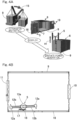
Fig. 4A shows a set of perspective views illustrating an example method for installing the charging station; -
Fig. 4B shows a horizontal cross sectional view of the charging station in a closed position of the door; -
Fig. 5 shows a horizontal cross sectional view of the charging station, schematically illustrating an example use scenario in which an electric vehicle may be charged; -
Fig. 6 shows a horizontal cross sectional view of the charging station, schematically illustrating another example use scenario in which an electric vehicle may be charged; -
Fig. 7 shows a horizontal cross sectional view of the charging station, schematically illustrating yet another example use scenario in which an electric vehicle may be charged; -
Fig. 8 shows a horizontal cross sectional view of the charging station, schematically illustrating yet another example use scenario in which an electric vehicle may be charged; -
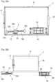
Fig. 9A shows a horizontal cross sectional view of a charging station in a closed position of a door, in accordance with another embodiment of the present invention; -
Fig. 9B shows a top plan view of the charging station in an open position of the door; and -
Fig. 9C shows a front elevational view of the charging station in an open position of the door. - Embodiments of the present invention will be described in connection with
Figs. 1 to 8 . - As illustrated in
Fig. 1 , in an embodiment, a charging station 1 includes acharger device 4 capable of charging avehicle battery 3 of anelectric vehicle 2. For example, eachelectric vehicle 2 is an electric motorcycle, an electric motor tricycle, or an electrically assisted bicycle. Eachelectric vehicle 2 includes avehicle battery 3 and a motor (not shown) driven with power supplied from thevehicle battery 3 to provide traction. Eachelectric vehicle 2 in the instant example can be rented out, for a selected duration of time or for a selected term period, to a customer who has entered into an agreement regarding the use of theelectric vehicle 2. - In addition to the
charger device 4, the charging station 1 includes a windturbine generator unit 5, aphotovoltaic generator unit 6, arechargeable battery 7, acontroller unit 8, and astructure 9 which is shown inFig. 2 . - As illustrated in
Fig. 5 , thestructure 9 houses thecharger device 4, therechargeable battery 7, thecontroller unit 8, and more than oneelectric vehicle 2. Further, thestructure 9 is transportable, is shaped as a box including double door-type gates electric vehicle 2, and comes with rigidity and security. Thegates Fig. 2 , thestructure 9 includes atop wall 9a and abottom wall 9b that are substantially rectangular in shape, and fourperimeter walls 9c arranged between thetop wall 9a and thebottom wall 9b, thereby forming a generally cuboid shape as a whole. In particular, thestructure 9 comprises a shipping container. - The "shipping container" used herein is preferably a container having a size that complies with a standard for freight transport containers - such as a domestic standard for container transport. For instance, the "standard" in this context may be a standard established by a relevant domestic administrative agency or an international organization such as the International Organization for Standardization (ISO), or may even be a JR container which serves as a de-facto standard for railroad freight transport containers in Japan.
- Being configured as a shipping container, the
structure 9 can be transferred using a variety of transport means such as truck, railroad, ship, or airplane. With an excellent rigidity, the shipping container can also protect devices and others stored therein from possible malfunctions that may be caused by vibrations and impacts during a transport process. - As illustrated in
Fig. 3 , the windturbine generator unit 5 includes awind turbine 12 and agenerator 13 configured to be driven by thewind turbine 12 to generate power. Thewind turbine 12 is configured as a vertical axis wind turbine. In particular, thewind turbine 12 includes a plurality ofblades 12a (or twoblades 12a in the instant example) and ablade support 12b providing support for theblades 12a. Each of theblades 12a extends in a vertical direction, whereas theblade support 12b is rotatably supported about a vertical axis on an upper end of atower 14 by means of a bearing arrangement (not shown). The twoblades 12a are positioned to be angularly offset from each other by 180 degrees about an axis of thetower 14. Further, thetower 14 is secured centrally to an upper part of one of theperimeter walls 9c of the structure 9 (Fig. 2 ). - The
generator 13 of the windturbine generator unit 5 is disposed inside agenerator casing 13a that is mounted to the top of thetower 14. Stationary race(s) of the bearing arrangement is/are fitted to thegenerator casing 13a, whereas rotational race(s) of the bearing arrangement is/are coupled to theblade support 12b. Thegenerator 13 generates power as a rotor of thegenerator 13 rotates inside thegenerator casing 13a along with the rotational race(s) in response to the rotation of thewind turbine 12. For example, an induction generator or a synchronous generator can be used for thegenerator 13. - A vertical axis wind turbine can be configured in a relatively small size but still can receive wind to generate power and is, therefore, suited as the
wind turbine 12 for the windturbine generator unit 5 to be installed to thetransportable structure 9. Nevertheless, the wind turbine may alternatively be a horizontal axis wind turbine. - The
photovoltaic generator unit 6 includes asolar panel 6a configured to receive sunlight for photoelectric conversion and apanel mount 6b attaching thesolar panel 6a to thestructure 9. In the instant example, thesolar panel 6a is attached onto thetop wall 9a of thestructure 9 by means of thepanel mount 6b. Depending on the direction of solar radiation or the installation environment, thesolar panel 6a may alternatively be disposed on given one(s) of theperimeter walls 9c (Fig. 2 ) of thestructure 9 or deployed around thestructure 9. It should also be noted that thepanel mount 6b in the illustrated example may be equipped with a mechanism capable of changing the angle of thesolar panel 6a according to the direction of the sun. - As illustrated in
Fig. 1 , therechargeable battery 7 stores power generated by the windturbine generator unit 5 and thephotovoltaic generator unit 6 and delivers the stored power to thevehicle battery 3 when demanded to do so. Thecontroller unit 8 is configured to execute control so as to direct power generated by thesepower generator units charger device 4, into therechargeable battery 7 and draw power accumulated in therechargeable battery 7, via thecharger device 4, into thevehicle battery 3. For instance, thecontroller unit 8 includes an AC to DC converter or the like configured to convert the AC power generated by thepower generator units rechargeable battery 7. - The amount of power which can be generated by natural energy generator unit(s) like the wind
turbine generator unit 5 and thephotovoltaic generator unit 6 and which can be stored in therechargeable battery 7 are under the constraints of the power generating performance of the natural energy generator unit(s) and the operational regulations in effect, thus, limiting the capacity of therechargeable battery 7. For this reason, thecontroller unit 8 can controllably charge thevehicle battery 3 of more than oneelectric vehicle 2 without bringing about a reduction in the capacity or service life of therechargeable battery 7. - As illustrated in
Fig. 4A , firstly, thestructure 9 housing the windturbine generator unit 5, thephotovoltaic generator unit 6, the charger device 4 (Fig. 1 ), therechargeable battery 7, the controller unit 8 (Fig. 3 ) and the like is transported to a desired installation site by, for example, a truck loader crane (or a truck-mounted crane). Then, thestructure 9 is unloaded by acrane 15 of the truck-mounted crane. Alternatively, a forklift, a gantry crane (both not shown), etc. may be used to unload thestructure 9 from a corresponding one of various possible transport means. It should also be noted that thestructure 9 may be transported with electric vehicle(s) accommodated inside in addition to the power generator units and others. At least one of the windturbine generator unit 5, thephotovoltaic generator unit 6, the charger device 4 (Fig. 1 ), and therechargeable battery 7 may be transported separately from thestructure 9. - Subsequently, the wind
turbine generator unit 5 and thephotovoltaic generator unit 6 housed in thestructure 9 are deployed out of the container, in order for thesepower generator units structure 9. In the instant example, adoor 16 on a front side of thestructure 9 is equipped with awind turbine holder 17 configured to hold the windturbine generator unit 5, which is stored in thestructure 9, along the interior side of thedoor 16, as shown inFig. 4B . - Thanks to the
wind turbine holder 17 equipped on thedoor 16, the windturbine generator unit 5, which is held along the interior side of thedoor 16 and positioned outside of the container by opening thedoor 16, can be simply raised upwards and installed as indicated with an arrow A1 without the use of a ramp, etc., as shown inFig. 4A , in order to be mounted to a desired location. Then, each of thepower generator units -
Fig. 5 shows an example of the charging station 1 in which thestructure 9 is embodied as a 10-foot container where theelectric vehicle 2 may be charged. Thestructure 9 is provided with one of thegates 10 at one of the lateral faces of thestructure 9 to permit entry of theelectric vehicle 2 and provided with the other of thegates 11 at another one of the lateral faces of thestructure 9 that is opposite thereto to permit exit of theelectric vehicle 2. For instance, a customer for or a manager of the charging station 1 uses a chargingcable 18, etc. to establish an electrical connection between thecharger device 4 and the vehicle battery of theelectric vehicle 2, which has entered thestructure 9, to charge the vehicle battery. - During this process, the
controller unit 8 executes control so as to draw power accumulated in therechargeable battery 7, via thecharger device 4, into the vehicle battery. Thecontroller unit 8 can even charge, via thecharger device 4, anindividual vehicle battery 3 separated from theelectric vehicle 2 with power that is accumulated in therechargeable battery 7. A customer who is a user of theelectric vehicle 2 can let theelectric vehicle 2 exit through thegate 11 once the vehicle battery has been charged, and can start using theelectric vehicle 2. - As illustrated in
Fig. 6 , the vehicle battery of theelectric vehicle 2 can not only be charged inside the container but can also be charged when theelectric vehicle 2 is parked outside the container. In this case, the vehicle battery of theelectric vehicle 2 can be charged outside the container when, for example, there is not enough space for theelectric vehicle 2 to enter the container, thereby enhancing the usability experienced by a customer. -
Figs. 7 and 8 show examples of the charging station 1 in which thestructure 9 is embodied as a 20-foot container where theelectric vehicle 2 may be charged. The vehicle battery of theelectric vehicle 2 can be charged inside the container, as shown inFig. 7 . Or, the vehicle battery of theelectric vehicle 2, whether inside or outside the container, can be charged, as shown inFig. 8 . - According to the charging station 1 that has been discussed thus far, the
vehicle battery 3 of theelectric vehicle 2 can be charged with power generated by natural energy generator unit(s) in the form of the windturbine generator unit 5 and thephotovoltaic generator unit 6 as inFig. 1 . Thus, thevehicle battery 3 of theelectric vehicle 2 can be charged even at locations where there is no electricity available from a grid power system. Further, the setup cost in areas where there is no electricity available and where it is, therefore, difficult to secure power supply can be reduced thanks to the use of the natural energy generator unit(s) - thus, obviating the need to conduct construction works for newly installing utility poles and power lines - and thanks to the fact that thestructure 9 is transportable. Since a shipping container containing thepower generator units charger device 4, therechargeable battery 7, and thecontroller unit 8 in a single package is used for installation, it is possible to prepare a charging station 1 in an easier setup procedure and at a lower cost than by constructing the building of the station from scratch. - For these reasons, the charging station 1 having the above configuration can be more readily installed than previous charging stations that make use of a grid power system.
- The
structure 9 is shaped as a box including thegates electric vehicle 2 as inFig. 5 and comes with rigidity and security. Therefore, by keeping theelectric vehicle 2, the charger device, or others inside, thestructure 9 can mitigate theft of and mischief on theseelectric vehicle 2, charger device, and others, thereby exceling in crime prevention. - Since the charging station 1 is equipped with more than one natural energy generator unit including the wind
turbine generator unit 5 and thephotovoltaic generator unit 6 as inFig. 1 , the amount of power that can be generated is insensitive to constrains including weather conditions, a natural environment such as a terrain, and daytime versus nighttime, thus, allowing for power to be accumulated efficiently in therechargeable battery 7. Hence, a vast range of locations can be chosen as a site to install and operate the charging station 1. - Now, additional embodiments will be described. In the remainder of the discussion, features corresponding to those previously discussed features with respect to preceding embodiment(s) will be indicated with the same reference symbols and will not be described again to avoid redundancy. Where only a subset of features are discussed, the remaining features should be regarded as analogous to those of the preceding embodiment(s) unless otherwise noted. Identical features produce identical benefits and effects. In addition to particular combinations of features discussed with respect to each of the embodiments, the embodiments themselves can be partially combined with each other, unless such combinations are found to be inoperable.
- As illustrated in
Fig. 9A , the charging station 1 may include ahydroelectric generator unit 19 configured to be able to be installed to a waterway and configured to be able to be housed in and taken out of thestructure 9 as shown inFig. 9B . For example, thehydroelectric generator unit 19 includes a base 20 configured to be installed to the waterway, ahydroelectric turbine 21, and aframe 22 carrying thehydroelectric turbine 21, and agenerator 23 supported by theframe 22 and configured to generate power from rotation of thehydroelectric turbine 21, as shown inFig. 9C . - In the instant example, the
door 16 on a front side of thestructure 9 is equipped with ahydroelectric turbine holder 24 configured to hold the hydroelectricturbine generator unit 19, which is stored in thestructure 9, along the interior side of thedoor 16. Thanks to thehydroelectric turbine holder 24 equipped on thedoor 16, thehydroelectric generator unit 19, which is held along the interior side of thedoor 16 and positioned outside of the container by opening thedoor 16, can be loaded on a wagon, etc. without the use of a ramp, etc., in order to be transferred to a desired installation site. - Since such a charging station is equipped with the wind
turbine generator unit 5, the photovoltaic generator unit 6 (Fig. 1 ), and thehydroelectric generator unit 19, it is possible to effectively exploit natural energy in an adaptive manner to the surrounding environment of the installation site of the charging station 1. In addition, more than one type of natural energy power generation may be combined, thus, allowing for power accumulation that adapts to changes in the weather. Otherwise, the benefits and effects analogous to those of the preceding embodiment(s) are achieved. - As illustrated in
Fig. 1 , the charging system includes more than one charging station 1 according to a given one of the embodiments and a communication system configured to present an operation status of these charging stations 1 to a customer who is a user of theelectric vehicle 2. For instance, the communication system includes aserver 25 and acommunication device 26 provided in each of the charging stations 1 and theserver 25. - The
controller unit 8 in each of the charging stations 1 communicates, via thecommunication device 26 to theserver 25, an operation status including information on, for example, whether acharger device 4 is currently available or not, the number of such charger devices, and whether avehicle battery 3 present at each charging station 1 has been fully charged or not. Acomputer 25a of theserver 25 logs the received operation status in an overwritable manner. The received operation status is presented to a customer over a network. For example, the customer can use a mobile device such as a smartphone to access theserver 25 over a network and view the operation status of a charging station 1 which he/she considers using. Hence, the usability experienced by a customer who is a user of theelectric vehicle 2 is enhanced. - The charging station 1 may include a hydrogen
power generator unit 27 for a natural energy generator unit. In the hydrogenpower generator unit 27, for example, introduced air is compressed by a compressor and delivered to a combustor unit into which hydrogen is injected for combustion, producing high temperature, high pressure combustion gas that actuates a turbine. The turbine creates power to drive a generator. - Power generator units may be combined as needed from among the aforementioned plurality of types of power generator units, so that one or more power generator units from among the plurality of types of power generator units can be utilized.
- The charging station can even be used as a rental garage in which a customer can store, for example, an electric vehicle that he/she owns.
- The charging station can also be used as a base camp for a disaster relief operation. Disaster relief workers and disaster victims can use power generated by the natural energy generator unit(s) to operate necessity electronics, mobile devices, etc.
- The charging station may provide more than one electric vehicle for use as means of transportation in depopulated areas.
- As an alternative to the shipping container, the structure may comprise a simple transportable building.
- The controller unit may include an inverter, etc., configured to convert power accumulated in the rechargeable battery to AC power having a sinusoidal waveform similar to that of the power mains or AC power having a square waveform.
- The charging station can even include a grid power system interface configured to receive power supply from a grid power system. For example, by installing such a charging station with the grid power system interface on a location where it can connect to a grid power system, the grid power system can be utilized as a main power source while utilizing the charging station as a backup power source in the event of power outage.
- The charging station may even charge not only the vehicle battery of the electric vehicle but also a vehicle battery of a gasoline engine-powered motorcycle or motor tricycle (which will hereinafter be referred to collectively as an "engine-powered vehicle"). In this case, an engine-powered vehicle with an exhausted or deteriorated vehicle battery can be readily rescued at the charging station or near the charging station.
- A charging station in accordance with this proposed reference example includes: a charger device capable of charging at least one of a vehicle battery of an electric vehicle or a vehicle battery of an engine-powered vehicle; at least one power generator unit selected from a group consisting of a wind turbine generator unit, a photovoltaic generator unit, and a hydroelectric generator unit; a rechargeable battery configured to store power generated by the power generator unit; a controller unit configured to execute control so as to direct power generated by the power generator unit, via the charger device, into the rechargeable battery and draw power accumulated in the rechargeable battery, via the charger device, into the vehicle battery; and a structure, which is transportable, with rigidity and security configured to house the charger device, the rechargeable battery, and the controller unit and shaped as a box including a gate configured to permit entry and exit of the electric vehicle or the engine-powered vehicle.
- While preferred embodiments have thus been discussed with reference to the drawings, various additions, modifications, or omissions can be made therein without departing from the principle of the present invention and are, thus, also encompassed within the scope of the present invention.
-
- 1
- charging station
- 2
- electric vehicle
- 3
- vehicle battery
- 4
- charger device
- 5
- wind turbine generator unit
- 6
- photovoltaic generator unit
- 7
- rechargeable battery
- 8
- controller unit
- 9
- structure
- 10, 11
- gate
Claims (3)
- A charging station comprising:a charger device capable of charging a vehicle battery of an electric vehicle;at least one power generator unit selected from a group consisting of a wind turbine generator unit, a photovoltaic generator unit, and a hydroelectric generator unit;a rechargeable battery configured to store power generated by the power generator unit;a controller unit configured to execute control so as to direct power generated by the power generator unit, via the charger device, into the rechargeable battery and draw power accumulated in the rechargeable battery, via the charger device, into the vehicle battery; anda structure, which is transportable, with rigidity and security, the structure being configured to house the charger device, the rechargeable battery, and the controller unit and shaped as a box including a gate configured to permit entry and exit of the electric vehicle.
- The charging station as claimed in claim 1, wherein the structure comprises a shipping container.
- A charging system comprising:more than one charging station as claimed in claim 1 or 2; anda communication system configured to present an operation status of said more than one charging station to a customer who is a user of the electric vehicle.
Applications Claiming Priority (2)
| Application Number | Priority Date | Filing Date | Title |
|---|---|---|---|
| JP2021087155A JP2022180195A (en) | 2021-05-24 | 2021-05-24 | Charging station and charging system |
| PCT/JP2022/020558 WO2022249931A1 (en) | 2021-05-24 | 2022-05-17 | Charging station and charging system |
Publications (2)
| Publication Number | Publication Date |
|---|---|
| EP4350933A1 true EP4350933A1 (en) | 2024-04-10 |
| EP4350933A4 EP4350933A4 (en) | 2025-05-07 |
Family
ID=84229965
Family Applications (1)
| Application Number | Title | Priority Date | Filing Date |
|---|---|---|---|
| EP22811204.1A Pending EP4350933A4 (en) | 2021-05-24 | 2022-05-17 | CHARGING STATION AND CHARGING SYSTEM |
Country Status (3)
| Country | Link |
|---|---|
| EP (1) | EP4350933A4 (en) |
| JP (1) | JP2022180195A (en) |
| WO (1) | WO2022249931A1 (en) |
Families Citing this family (4)
| Publication number | Priority date | Publication date | Assignee | Title |
|---|---|---|---|---|
| FR3149554A1 (en) * | 2023-06-09 | 2024-12-13 | Be Green Mobility | CHARGING SYSTEM COMPRISING LOCATION TERMINALS FOR ELECTRIC VEHICLES |
| PL445862A1 (en) * | 2023-08-22 | 2025-02-24 | Sylwester Jędra | An electrical power supply unit and an electric vehicle charging station containing that power supply unit |
| WO2025109667A1 (en) * | 2023-11-21 | 2025-05-30 | ヤマハ発動機株式会社 | Energy supply station |
| ES1310241Y (en) * | 2024-02-05 | 2024-11-25 | Tormo Sanchez Jorge | Prefabricated station for storage, recharging and maintenance of personal mobility vehicles |
Family Cites Families (10)
| Publication number | Priority date | Publication date | Assignee | Title |
|---|---|---|---|---|
| JP2006158087A (en) | 2004-11-29 | 2006-06-15 | Yamaha Motor Co Ltd | Charging system for electric vehicle |
| JP4731607B2 (en) * | 2007-02-19 | 2011-07-27 | 株式会社エネルギー応用技術研究所 | Power supply device for quick charge and power supply method for quick charge |
| JP2015001933A (en) * | 2013-06-18 | 2015-01-05 | 新明和工業株式会社 | Operation management system and method for electric vehicle |
| KR20170138663A (en) * | 2016-06-08 | 2017-12-18 | (주)화이버 옵틱코리아 | Drone Station |
| US20180069416A1 (en) * | 2016-09-08 | 2018-03-08 | Michael Wayne Brace | Electric Bicycle Rental Outlet For Use In Off-Grid Locations |
| JP6726725B2 (en) * | 2017-11-01 | 2020-07-22 | ヤマハ発動機株式会社 | SHARING MANAGEMENT DEVICE FOR LEAN VEHICLE WITH POWER SOURCE AND SHARING MANAGEMENT METHOD FOR LEAN VEHICLE WITH POWER SOURCE |
| JP7126124B2 (en) * | 2018-10-04 | 2022-08-26 | パナソニックIpマネジメント株式会社 | Charging system, charging method, and program |
| JP2020169532A (en) * | 2019-04-05 | 2020-10-15 | Ntn株式会社 | Mobile store with renewable energy generator |
| CN209870141U (en) * | 2019-04-12 | 2019-12-31 | 厦门深蓝动力科技有限公司 | Mobile charging station |
| DE102020128116A1 (en) * | 2020-10-26 | 2022-04-28 | Stefan Drössler | E-Service module |
-
2021
- 2021-05-24 JP JP2021087155A patent/JP2022180195A/en active Pending
-
2022
- 2022-05-17 WO PCT/JP2022/020558 patent/WO2022249931A1/en not_active Ceased
- 2022-05-17 EP EP22811204.1A patent/EP4350933A4/en active Pending
Also Published As
| Publication number | Publication date |
|---|---|
| JP2022180195A (en) | 2022-12-06 |
| EP4350933A4 (en) | 2025-05-07 |
| WO2022249931A1 (en) | 2022-12-01 |
Similar Documents
| Publication | Publication Date | Title |
|---|---|---|
| CN115298436B (en) | Mobile autonomous solar wind power station | |
| WO2022249931A1 (en) | Charging station and charging system | |
| US11990865B2 (en) | Rapidly deploying transportable solar panel systems and methods of using same | |
| US20080217998A1 (en) | Renewable energy power systems | |
| US20130042542A1 (en) | Carport for a Motor Vehicle | |
| GB2502661A (en) | A mobile solar power plant | |
| CN109477463B (en) | Mobile, self-contained, scalable, self-deploying, monitorable, remotely reprogrammable power generation systems | |
| EP3951119A1 (en) | Portable facility provided with natural energy power generation unit | |
| KR100900032B1 (en) | Battery built-in street light | |
| US20150318702A1 (en) | Mobile energy storage module | |
| CN108638912A (en) | A kind of new-energy automobile charging pile with safeguard function | |
| EP3644395A1 (en) | Battery energy storage system architecture | |
| US20220017295A1 (en) | Mobile shop provided with natural energy power generation device | |
| US12308650B2 (en) | Energy storage unit docking stations | |
| US11677263B2 (en) | Off grid power supply system | |
| JP2010252587A (en) | Charging stand | |
| GB2508577A (en) | DC power system including DC alternator and renewable energy sources | |
| JP7261066B2 (en) | Portable facility with natural energy power generation unit | |
| JP6801992B2 (en) | Power storage system | |
| CN118004397A (en) | Power supply device for battery-powered ship and battery-powered ship | |
| CN204391811U (en) | A kind of electric automobile multiple-energy-source compound charging station | |
| WO2022235619A1 (en) | Modular charging system | |
| CN203457099U (en) | Solar energy power supply system | |
| CN221914571U (en) | Power supply device for battery power ship and battery power ship | |
| US10138869B2 (en) | Micro wind cell |
Legal Events
| Date | Code | Title | Description |
|---|---|---|---|
| STAA | Information on the status of an ep patent application or granted ep patent |
Free format text: STATUS: THE INTERNATIONAL PUBLICATION HAS BEEN MADE |
|
| PUAI | Public reference made under article 153(3) epc to a published international application that has entered the european phase |
Free format text: ORIGINAL CODE: 0009012 |
|
| STAA | Information on the status of an ep patent application or granted ep patent |
Free format text: STATUS: REQUEST FOR EXAMINATION WAS MADE |
|
| 17P | Request for examination filed |
Effective date: 20231221 |
|
| AK | Designated contracting states |
Kind code of ref document: A1 Designated state(s): AL AT BE BG CH CY CZ DE DK EE ES FI FR GB GR HR HU IE IS IT LI LT LU LV MC MK MT NL NO PL PT RO RS SE SI SK SM TR |
|
| DAV | Request for validation of the european patent (deleted) | ||
| DAX | Request for extension of the european patent (deleted) | ||
| A4 | Supplementary search report drawn up and despatched |
Effective date: 20250409 |
|
| RIC1 | Information provided on ipc code assigned before grant |
Ipc: B60L 53/57 20190101ALI20250403BHEP Ipc: B60L 53/53 20190101ALI20250403BHEP Ipc: B60L 53/52 20190101ALI20250403BHEP Ipc: B60L 53/51 20190101ALI20250403BHEP Ipc: B60L 53/30 20190101ALI20250403BHEP Ipc: H02J 13/00 20060101ALI20250403BHEP Ipc: H02J 7/35 20060101ALI20250403BHEP Ipc: G06Q 30/06 20230101ALI20250403BHEP Ipc: H02J 7/00 20060101AFI20250403BHEP |