EP4350839A1 - Battery pack for supplying power to an electronic device - Google Patents
Battery pack for supplying power to an electronic device Download PDFInfo
- Publication number
- EP4350839A1 EP4350839A1 EP23197026.0A EP23197026A EP4350839A1 EP 4350839 A1 EP4350839 A1 EP 4350839A1 EP 23197026 A EP23197026 A EP 23197026A EP 4350839 A1 EP4350839 A1 EP 4350839A1
- Authority
- EP
- European Patent Office
- Prior art keywords
- battery pack
- equal
- housing
- pack according
- cell
- Prior art date
- Legal status (The legal status is an assumption and is not a legal conclusion. Google has not performed a legal analysis and makes no representation as to the accuracy of the status listed.)
- Pending
Links
- 230000017525 heat dissipation Effects 0.000 claims abstract description 33
- 230000002093 peripheral effect Effects 0.000 claims abstract description 13
- 229910052751 metal Inorganic materials 0.000 claims description 31
- 239000002184 metal Substances 0.000 claims description 31
- 230000004323 axial length Effects 0.000 claims description 6
- 238000003466 welding Methods 0.000 claims description 6
- 238000000034 method Methods 0.000 description 7
- 230000008878 coupling Effects 0.000 description 6
- 238000010168 coupling process Methods 0.000 description 6
- 238000005859 coupling reaction Methods 0.000 description 6
- 230000000712 assembly Effects 0.000 description 4
- 238000000429 assembly Methods 0.000 description 4
- 238000007789 sealing Methods 0.000 description 4
- 238000009434 installation Methods 0.000 description 3
- 230000008569 process Effects 0.000 description 3
- 238000007599 discharging Methods 0.000 description 2
- 238000004146 energy storage Methods 0.000 description 2
- 239000000463 material Substances 0.000 description 2
- 238000005192 partition Methods 0.000 description 2
- 125000006850 spacer group Chemical group 0.000 description 2
- 229910000838 Al alloy Inorganic materials 0.000 description 1
- 102100026456 POU domain, class 3, transcription factor 3 Human genes 0.000 description 1
- 101710133393 POU domain, class 3, transcription factor 3 Proteins 0.000 description 1
- 238000006243 chemical reaction Methods 0.000 description 1
- 238000004891 communication Methods 0.000 description 1
- 230000007812 deficiency Effects 0.000 description 1
- 238000013461 design Methods 0.000 description 1
- 238000005516 engineering process Methods 0.000 description 1
- 238000009413 insulation Methods 0.000 description 1
- 239000012212 insulator Substances 0.000 description 1
- 238000002955 isolation Methods 0.000 description 1
- 238000004519 manufacturing process Methods 0.000 description 1
- 238000005259 measurement Methods 0.000 description 1
- 230000000149 penetrating effect Effects 0.000 description 1
- 239000000565 sealant Substances 0.000 description 1
- 238000006467 substitution reaction Methods 0.000 description 1
- 238000012546 transfer Methods 0.000 description 1
- 230000009466 transformation Effects 0.000 description 1
- 238000000844 transformation Methods 0.000 description 1
Images




Classifications
-
- H—ELECTRICITY
- H01—ELECTRIC ELEMENTS
- H01M—PROCESSES OR MEANS, e.g. BATTERIES, FOR THE DIRECT CONVERSION OF CHEMICAL ENERGY INTO ELECTRICAL ENERGY
- H01M50/00—Constructional details or processes of manufacture of the non-active parts of electrochemical cells other than fuel cells, e.g. hybrid cells
- H01M50/20—Mountings; Secondary casings or frames; Racks, modules or packs; Suspension devices; Shock absorbers; Transport or carrying devices; Holders
- H01M50/244—Secondary casings; Racks; Suspension devices; Carrying devices; Holders characterised by their mounting method
-
- H—ELECTRICITY
- H01—ELECTRIC ELEMENTS
- H01M—PROCESSES OR MEANS, e.g. BATTERIES, FOR THE DIRECT CONVERSION OF CHEMICAL ENERGY INTO ELECTRICAL ENERGY
- H01M10/00—Secondary cells; Manufacture thereof
- H01M10/42—Methods or arrangements for servicing or maintenance of secondary cells or secondary half-cells
- H01M10/425—Structural combination with electronic components, e.g. electronic circuits integrated to the outside of the casing
-
- H—ELECTRICITY
- H01—ELECTRIC ELEMENTS
- H01M—PROCESSES OR MEANS, e.g. BATTERIES, FOR THE DIRECT CONVERSION OF CHEMICAL ENERGY INTO ELECTRICAL ENERGY
- H01M10/00—Secondary cells; Manufacture thereof
- H01M10/60—Heating or cooling; Temperature control
- H01M10/61—Types of temperature control
- H01M10/613—Cooling or keeping cold
-
- H—ELECTRICITY
- H01—ELECTRIC ELEMENTS
- H01M—PROCESSES OR MEANS, e.g. BATTERIES, FOR THE DIRECT CONVERSION OF CHEMICAL ENERGY INTO ELECTRICAL ENERGY
- H01M10/00—Secondary cells; Manufacture thereof
- H01M10/60—Heating or cooling; Temperature control
- H01M10/62—Heating or cooling; Temperature control specially adapted for specific applications
- H01M10/623—Portable devices, e.g. mobile telephones, cameras or pacemakers
- H01M10/6235—Power tools
-
- H—ELECTRICITY
- H01—ELECTRIC ELEMENTS
- H01M—PROCESSES OR MEANS, e.g. BATTERIES, FOR THE DIRECT CONVERSION OF CHEMICAL ENERGY INTO ELECTRICAL ENERGY
- H01M10/00—Secondary cells; Manufacture thereof
- H01M10/60—Heating or cooling; Temperature control
- H01M10/64—Heating or cooling; Temperature control characterised by the shape of the cells
- H01M10/643—Cylindrical cells
-
- H—ELECTRICITY
- H01—ELECTRIC ELEMENTS
- H01M—PROCESSES OR MEANS, e.g. BATTERIES, FOR THE DIRECT CONVERSION OF CHEMICAL ENERGY INTO ELECTRICAL ENERGY
- H01M10/00—Secondary cells; Manufacture thereof
- H01M10/60—Heating or cooling; Temperature control
- H01M10/65—Means for temperature control structurally associated with the cells
- H01M10/655—Solid structures for heat exchange or heat conduction
-
- H—ELECTRICITY
- H01—ELECTRIC ELEMENTS
- H01M—PROCESSES OR MEANS, e.g. BATTERIES, FOR THE DIRECT CONVERSION OF CHEMICAL ENERGY INTO ELECTRICAL ENERGY
- H01M10/00—Secondary cells; Manufacture thereof
- H01M10/60—Heating or cooling; Temperature control
- H01M10/65—Means for temperature control structurally associated with the cells
- H01M10/655—Solid structures for heat exchange or heat conduction
- H01M10/6551—Surfaces specially adapted for heat dissipation or radiation, e.g. fins or coatings
-
- H—ELECTRICITY
- H01—ELECTRIC ELEMENTS
- H01M—PROCESSES OR MEANS, e.g. BATTERIES, FOR THE DIRECT CONVERSION OF CHEMICAL ENERGY INTO ELECTRICAL ENERGY
- H01M10/00—Secondary cells; Manufacture thereof
- H01M10/60—Heating or cooling; Temperature control
- H01M10/65—Means for temperature control structurally associated with the cells
- H01M10/655—Solid structures for heat exchange or heat conduction
- H01M10/6554—Rods or plates
-
- H—ELECTRICITY
- H01—ELECTRIC ELEMENTS
- H01M—PROCESSES OR MEANS, e.g. BATTERIES, FOR THE DIRECT CONVERSION OF CHEMICAL ENERGY INTO ELECTRICAL ENERGY
- H01M10/00—Secondary cells; Manufacture thereof
- H01M10/60—Heating or cooling; Temperature control
- H01M10/65—Means for temperature control structurally associated with the cells
- H01M10/655—Solid structures for heat exchange or heat conduction
- H01M10/6554—Rods or plates
- H01M10/6555—Rods or plates arranged between the cells
-
- H—ELECTRICITY
- H01—ELECTRIC ELEMENTS
- H01M—PROCESSES OR MEANS, e.g. BATTERIES, FOR THE DIRECT CONVERSION OF CHEMICAL ENERGY INTO ELECTRICAL ENERGY
- H01M50/00—Constructional details or processes of manufacture of the non-active parts of electrochemical cells other than fuel cells, e.g. hybrid cells
- H01M50/20—Mountings; Secondary casings or frames; Racks, modules or packs; Suspension devices; Shock absorbers; Transport or carrying devices; Holders
- H01M50/204—Racks, modules or packs for multiple batteries or multiple cells
- H01M50/207—Racks, modules or packs for multiple batteries or multiple cells characterised by their shape
- H01M50/209—Racks, modules or packs for multiple batteries or multiple cells characterised by their shape adapted for prismatic or rectangular cells
-
- H—ELECTRICITY
- H01—ELECTRIC ELEMENTS
- H01M—PROCESSES OR MEANS, e.g. BATTERIES, FOR THE DIRECT CONVERSION OF CHEMICAL ENERGY INTO ELECTRICAL ENERGY
- H01M50/00—Constructional details or processes of manufacture of the non-active parts of electrochemical cells other than fuel cells, e.g. hybrid cells
- H01M50/20—Mountings; Secondary casings or frames; Racks, modules or packs; Suspension devices; Shock absorbers; Transport or carrying devices; Holders
- H01M50/204—Racks, modules or packs for multiple batteries or multiple cells
- H01M50/207—Racks, modules or packs for multiple batteries or multiple cells characterised by their shape
- H01M50/213—Racks, modules or packs for multiple batteries or multiple cells characterised by their shape adapted for cells having curved cross-section, e.g. round or elliptic
-
- H—ELECTRICITY
- H01—ELECTRIC ELEMENTS
- H01M—PROCESSES OR MEANS, e.g. BATTERIES, FOR THE DIRECT CONVERSION OF CHEMICAL ENERGY INTO ELECTRICAL ENERGY
- H01M50/00—Constructional details or processes of manufacture of the non-active parts of electrochemical cells other than fuel cells, e.g. hybrid cells
- H01M50/20—Mountings; Secondary casings or frames; Racks, modules or packs; Suspension devices; Shock absorbers; Transport or carrying devices; Holders
- H01M50/218—Mountings; Secondary casings or frames; Racks, modules or packs; Suspension devices; Shock absorbers; Transport or carrying devices; Holders characterised by the material
- H01M50/22—Mountings; Secondary casings or frames; Racks, modules or packs; Suspension devices; Shock absorbers; Transport or carrying devices; Holders characterised by the material of the casings or racks
- H01M50/227—Organic material
-
- H—ELECTRICITY
- H01—ELECTRIC ELEMENTS
- H01M—PROCESSES OR MEANS, e.g. BATTERIES, FOR THE DIRECT CONVERSION OF CHEMICAL ENERGY INTO ELECTRICAL ENERGY
- H01M50/00—Constructional details or processes of manufacture of the non-active parts of electrochemical cells other than fuel cells, e.g. hybrid cells
- H01M50/20—Mountings; Secondary casings or frames; Racks, modules or packs; Suspension devices; Shock absorbers; Transport or carrying devices; Holders
- H01M50/233—Mountings; Secondary casings or frames; Racks, modules or packs; Suspension devices; Shock absorbers; Transport or carrying devices; Holders characterised by physical properties of casings or racks, e.g. dimensions
-
- H—ELECTRICITY
- H01—ELECTRIC ELEMENTS
- H01M—PROCESSES OR MEANS, e.g. BATTERIES, FOR THE DIRECT CONVERSION OF CHEMICAL ENERGY INTO ELECTRICAL ENERGY
- H01M50/00—Constructional details or processes of manufacture of the non-active parts of electrochemical cells other than fuel cells, e.g. hybrid cells
- H01M50/20—Mountings; Secondary casings or frames; Racks, modules or packs; Suspension devices; Shock absorbers; Transport or carrying devices; Holders
- H01M50/258—Modular batteries; Casings provided with means for assembling
-
- H—ELECTRICITY
- H01—ELECTRIC ELEMENTS
- H01M—PROCESSES OR MEANS, e.g. BATTERIES, FOR THE DIRECT CONVERSION OF CHEMICAL ENERGY INTO ELECTRICAL ENERGY
- H01M50/00—Constructional details or processes of manufacture of the non-active parts of electrochemical cells other than fuel cells, e.g. hybrid cells
- H01M50/20—Mountings; Secondary casings or frames; Racks, modules or packs; Suspension devices; Shock absorbers; Transport or carrying devices; Holders
- H01M50/271—Lids or covers for the racks or secondary casings
-
- H—ELECTRICITY
- H01—ELECTRIC ELEMENTS
- H01M—PROCESSES OR MEANS, e.g. BATTERIES, FOR THE DIRECT CONVERSION OF CHEMICAL ENERGY INTO ELECTRICAL ENERGY
- H01M50/00—Constructional details or processes of manufacture of the non-active parts of electrochemical cells other than fuel cells, e.g. hybrid cells
- H01M50/20—Mountings; Secondary casings or frames; Racks, modules or packs; Suspension devices; Shock absorbers; Transport or carrying devices; Holders
- H01M50/284—Mountings; Secondary casings or frames; Racks, modules or packs; Suspension devices; Shock absorbers; Transport or carrying devices; Holders with incorporated circuit boards, e.g. printed circuit boards [PCB]
- H01M50/287—Fixing of circuit boards to lids or covers
-
- H—ELECTRICITY
- H01—ELECTRIC ELEMENTS
- H01M—PROCESSES OR MEANS, e.g. BATTERIES, FOR THE DIRECT CONVERSION OF CHEMICAL ENERGY INTO ELECTRICAL ENERGY
- H01M50/00—Constructional details or processes of manufacture of the non-active parts of electrochemical cells other than fuel cells, e.g. hybrid cells
- H01M50/20—Mountings; Secondary casings or frames; Racks, modules or packs; Suspension devices; Shock absorbers; Transport or carrying devices; Holders
- H01M50/289—Mountings; Secondary casings or frames; Racks, modules or packs; Suspension devices; Shock absorbers; Transport or carrying devices; Holders characterised by spacing elements or positioning means within frames, racks or packs
- H01M50/291—Mountings; Secondary casings or frames; Racks, modules or packs; Suspension devices; Shock absorbers; Transport or carrying devices; Holders characterised by spacing elements or positioning means within frames, racks or packs characterised by their shape
-
- H—ELECTRICITY
- H01—ELECTRIC ELEMENTS
- H01M—PROCESSES OR MEANS, e.g. BATTERIES, FOR THE DIRECT CONVERSION OF CHEMICAL ENERGY INTO ELECTRICAL ENERGY
- H01M50/00—Constructional details or processes of manufacture of the non-active parts of electrochemical cells other than fuel cells, e.g. hybrid cells
- H01M50/20—Mountings; Secondary casings or frames; Racks, modules or packs; Suspension devices; Shock absorbers; Transport or carrying devices; Holders
- H01M50/296—Mountings; Secondary casings or frames; Racks, modules or packs; Suspension devices; Shock absorbers; Transport or carrying devices; Holders characterised by terminals of battery packs
-
- H—ELECTRICITY
- H01—ELECTRIC ELEMENTS
- H01M—PROCESSES OR MEANS, e.g. BATTERIES, FOR THE DIRECT CONVERSION OF CHEMICAL ENERGY INTO ELECTRICAL ENERGY
- H01M50/00—Constructional details or processes of manufacture of the non-active parts of electrochemical cells other than fuel cells, e.g. hybrid cells
- H01M50/50—Current conducting connections for cells or batteries
- H01M50/502—Interconnectors for connecting terminals of adjacent batteries; Interconnectors for connecting cells outside a battery casing
- H01M50/507—Interconnectors for connecting terminals of adjacent batteries; Interconnectors for connecting cells outside a battery casing comprising an arrangement of two or more busbars within a container structure, e.g. busbar modules
-
- H—ELECTRICITY
- H01—ELECTRIC ELEMENTS
- H01M—PROCESSES OR MEANS, e.g. BATTERIES, FOR THE DIRECT CONVERSION OF CHEMICAL ENERGY INTO ELECTRICAL ENERGY
- H01M50/00—Constructional details or processes of manufacture of the non-active parts of electrochemical cells other than fuel cells, e.g. hybrid cells
- H01M50/50—Current conducting connections for cells or batteries
- H01M50/528—Fixed electrical connections, i.e. not intended for disconnection
-
- H—ELECTRICITY
- H01—ELECTRIC ELEMENTS
- H01M—PROCESSES OR MEANS, e.g. BATTERIES, FOR THE DIRECT CONVERSION OF CHEMICAL ENERGY INTO ELECTRICAL ENERGY
- H01M50/00—Constructional details or processes of manufacture of the non-active parts of electrochemical cells other than fuel cells, e.g. hybrid cells
- H01M50/50—Current conducting connections for cells or batteries
- H01M50/543—Terminals
- H01M50/552—Terminals characterised by their shape
- H01M50/559—Terminals adapted for cells having curved cross-section, e.g. round, elliptic or button cells
-
- H—ELECTRICITY
- H01—ELECTRIC ELEMENTS
- H01M—PROCESSES OR MEANS, e.g. BATTERIES, FOR THE DIRECT CONVERSION OF CHEMICAL ENERGY INTO ELECTRICAL ENERGY
- H01M2220/00—Batteries for particular applications
- H01M2220/30—Batteries in portable systems, e.g. mobile phone, laptop
-
- Y—GENERAL TAGGING OF NEW TECHNOLOGICAL DEVELOPMENTS; GENERAL TAGGING OF CROSS-SECTIONAL TECHNOLOGIES SPANNING OVER SEVERAL SECTIONS OF THE IPC; TECHNICAL SUBJECTS COVERED BY FORMER USPC CROSS-REFERENCE ART COLLECTIONS [XRACs] AND DIGESTS
- Y02—TECHNOLOGIES OR APPLICATIONS FOR MITIGATION OR ADAPTATION AGAINST CLIMATE CHANGE
- Y02E—REDUCTION OF GREENHOUSE GAS [GHG] EMISSIONS, RELATED TO ENERGY GENERATION, TRANSMISSION OR DISTRIBUTION
- Y02E60/00—Enabling technologies; Technologies with a potential or indirect contribution to GHG emissions mitigation
- Y02E60/10—Energy storage using batteries
Definitions
- the present application relates to an energy storage apparatus and, in particular, to a battery pack for supplying power to an electronic device.
- a battery pack for supplying power to a power tool typically has a housing made of plastic.
- a cell bracket capable of supporting the cell group is disposed in the housing.
- the cell bracket is fixedly connected to the housing, thereby ensuring that the cell group has a fixed position in the housing.
- Relatively large gaps typically exist between the peripheral surfaces of cells and the housing due to the existence of the cell bracket. Air in these gaps functions as a thermal insulator and slows down the heat transfer from the cells to the surrounding environment through the outer wall of the housing.
- an object of the present application is to provide a battery pack with better heat dissipation performance.
- a battery pack for supplying power to an electronic device includes: a housing formed with multiple accommodating cavities; and multiple cells, where a cell has an outer peripheral surface, and the distance between at least part of the outer peripheral surface and the intra-cavity wall surface of a respective accommodating cavity is greater than or equal to 0 mm and less than or equal to 1 mm.
- the area of the outer wall surface of the housing is larger than or equal to 4.5 dm 2 and smaller than or equal to 7 dm 2 .
- the ratio of the capacity of the battery pack to the heat dissipation area is higher than or equal to 1.2 Ah/dm 2 and lower than or equal to 3.5 Ah/dm 2 .
- the thermal conductivity of the housing is greater than or equal to 0.6 W/(m*k).
- the housing is provided with no heat dissipation opening.
- the housing has a cylindrical structure with the outer wall surface and two opposite end surfaces.
- the battery pack further includes: a panel assembly disposed on one end surface of the cylindrical structure; an electronic control assembly disposed on another end surface of the cylindrical structure; and an end cover assembly covering the panel assembly or the electronic control assembly.
- the battery pack further includes a fixing member configured to penetrate through and connect the end cover assembly, the panel assembly, the electronic control assembly, and the housing along the longitudinal extension direction of the cell.
- the housing is fixed to at least one of the panel assembly and the electronic control assembly through ultrasonic welding.
- a metal insert is disposed in the housing.
- the intra-cavity wall surface is formed with a fitting rib.
- the cell is a cylindrical cell, where the axial length of the cell is greater than or equal to 60 mm and less than or equal to 75 mm, and the diameter of the cross section of the cell is greater than or equal to 15 mm and less than or equal to 25 mm.
- the distance from the intra-cavity wall surface to the outer wall surface is greater than or equal to 1 mm and less than or equal to 5 mm.
- the battery pack further includes multiple metal terminals configured to be electrically connected to the multiple cells and used for outputting electrical energy, where the creepage distance between metal terminals is greater than 8 mm and less than or equal to 20 mm.
- the battery pack further includes a terminal block on which the multiple metal terminals are disposed and a terminal cover provided with grids corresponding to the multiple metal terminals, where the terminal cover is sealingly connected to the terminal block.
- the housing includes at least two sub-housings which are independent
- the battery pack further includes an intermediate member disposed between different ones of the at least two sub-housings and sealingly connected to the different sub-housings.
- a battery pack includes a housing including an inner wall and an outer wall, where the inner wall extends to form multiple accommodating cavities; and multiple cells disposed in the multiple accommodating cavities.
- a battery pack includes: a housing configured to have a cylindrical structure with an outer wall surface and two opposite end surfaces, where multiple accommodating cavities are formed in the cylindrical structure; and multiple cells disposed in the multiple accommodating cavities.
- the ratio of the capacity of the battery pack to the area of the cross section of the cylindrical structure is higher than or equal to 8 Ah/dm 2 and lower than or equal to 17 Ah/dm 2 .
- the thermal conductivity of the housing is greater than or equal to 0.6 W/(m*k).
- the housing is provided with no heat dissipation opening.
- a metal insert is disposed in the housing.
- the term "and/or” is a kind of association relationship describing the relationship between associated objects, which means that there can be three kinds of relationships.
- a and/or B can indicate that A exists alone, A and B exist simultaneously, and B exists alone.
- the character "/" in this application generally indicates that the contextual associated objects belong to an "and/or” relationship.
- connection may be direct connection, combination, coupling or installation, and may also be indirect connection, combination, coupling or installation.
- direct connection means that two members or assemblies are connected together without intermediaries
- indirect connection means that two members or assemblies are respectively connected with at least one intermediate members and the two members or assemblies are connected by the at least one intermediate members.
- connection and “coupling” are not limited to physical or mechanical connections or couplings, and may include electrical connections or couplings.
- a relative term (such as “about”, “approximately”, and “substantially) used in conjunction with quantity or condition includes a stated value and has a meaning dictated by the context.
- the relative term includes at least a degree of error associated with the measurement of a particular value, a tolerance caused by manufacturing, assembly, and use associated with the particular value, and the like.
- Such relative term should also be considered as disclosing the range defined by the absolute values of the two endpoints.
- the relative term may refer to plus or minus of a certain percentage (such as 1%, 5%, 10%, or more) of an indicated value. A value that did not use the relative term should also be disclosed as a particular value with a tolerance.
- “substantially” when expressing a relative angular position relationship may refer to adding or subtracting a certain degree (such as 1 degree, 5 degrees, 10 degrees or more) to the indicated angle.
- a function performed by an assembly may be performed by one assembly, multiple assemblies, one member, or multiple members.
- a function performed by a member may be performed by one member, an assembly, or a combination of members.
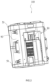
- a battery pack 100 shown in FIGS. 1 to 3 can store electrical energy to supply power to an electronic device.
- the electronic device may include a large-sized outdoor moving device such as a riding mower and a snow thrower.
- the electronic device may include some energy conversion devices, such as an adapter or an inverter, capable of converting the electrical energy outputted by the battery pack 100 so as to supply the power to other small-sized power tools such as handheld power tools and supply the power to some household electric devices such as a lamp, a mosquito-killing device, a fan, a cell phone, a computer, and other electric devices in daily lives.
- the inner wall surface of a housing 10 of the battery pack 100 shown in FIGS. 1 to 7 extends to be capable of forming multiple accommodating cavities 11.
- the housing 10 is directly used for supporting cells 20, and the outer wall surface 10a of the housing 10 is directly exposed to the external environment.
- each accommodating cavity 11 may be used for accommodating one cell 20.
- one accommodating cavity 11 may accommodate multiple cells 20.
- the line connecting the centers of cells 20 in any two accommodating cavities 11 may pass through the cavity walls of the accommodating cavities 11. That is to say, there are cavity walls as blocks between any two accommodating cavities 11 so that any two accommodating cavities 11 cannot communicate with each other.
- the housing 10 directly supports the cells 20, which may be understood as the case where no other intermediate member capable of supporting a cell 20 is disposed between an accommodating cavity 11 formed by the housing 10 and the cell 20, and the distance between the intra-cavity wall surface 11a of the accommodating cavity 11 and at least part of the outer peripheral surface 20a of the cell 20 is greater than or equal to 0 mm and less than or equal to 1 mm.
- the outer peripheral surface 20a of the corresponding cell 20 may be considered to be in contact with the intra-cavity wall surface 11a of the accommodating cavity 11 substantially.
- the heat of the cell 20 can be directly transferred to the intra-cavity wall surface 11a of the housing 10 and then dissipated to the outside through the outer wall surface 10a.
- the cell 20 is a cylindrical cell
- the accommodating cavity 11 is a cylindrical accommodating cavity adaptable to the cylindrical cell.
- each accommodating cavity 11 is larger than or equal to the outer diameter of the cell 20, and the gap between the intra-cavity wall surface 11a of the accommodating cavity 11 and the outer peripheral surface 20a of the cell 20 is very small.
- the cell 20 may be square, and the corresponding accommodating cavity 11 may also be square.
- the intra-cavity wall surface 11a of the accommodating cavity 11 may be formed with a fitting rib 12.
- the fitting rib 12 can function as a guide and conducts the heat from the cell 20 directly to the accommodating cavity 11 at the same time.
- a thermally-conductive flexible material may also be disposed between the cell 20 and the intra-cavity wall 11a so that the heat dissipation performance of the housing 10 is improved. It is to be noted that even if a flexible heat dissipation material is disposed between the cell 20 and the intra-cavity wall 11a, the housing 10 may also be considered to directly support the cell 20.
- the direct support in this example may be understood as the support of a hard structure to the cell 20.
- the thermal conductivity of the housing 10 is greater than or equal to 0.6 W/(m*k).
- the thermal conductivity of the housing 10 may be 0.6 W/(m*k), 0.7 W/(m*k), 0.8 W/(m*k), or 0.9 W/(m*k).
- the housing 10 is configured to have a cylindrical structure with two opposite end surfaces, where the multiple accommodating cavities 11 are disposed in the cylindrical structure.
- the radial extension direction of the accommodating cavity 11 substantially coincides with the mounting direction of the cell 20, and the end surfaces of the cylindrical structure may be substantially flush with two end surfaces of the cell 20 mounted in the accommodating cavity 11.
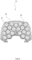
- the shape of the cross section 13 of the cylindrical structure shown in FIG. 6 substantially coincides with the shape in which the cells 20 are arranged in the housing 10.
- the shape of the connecting line of the tangent lines of the outer peripheral surfaces of outermost cells in the cylindrical structure substantially coincides with the shape of the cross section 13, that is to say, the connecting line of all the tangent lines of the outer peripheral surfaces of the outermost cells may form the outer wall surface of the cylindrical structure.
- the cross section 13 has a shape like a "crescent".
- the cross section 13 may have a circular shape, a square shape, or other special shapes, which is not limited in this example.
- the axial length of the cell 20 is greater than or equal to 60 mm and less than or equal to 75 mm, and the diameter of the cross section of the cell 20 is greater than or equal to 15 mm and less than or equal to 25 mm. Accordingly, the axial length of the housing 10 of the cylindrical structure is greater than or equal to 60 mm and less than or equal to 85 mm. In this example, the axial length of the housing 10 is slightly greater than the axial length of the cell 20.
- the area of the cross section 13 of the housing 10 is larger than or equal to 0.9 dm 2 and smaller than or equal to 1.1 dm 2 .
- the area of the cross section 13 may be 1 dm 2 .
- the ratio of the capacity of the battery pack 100 to the area of the cross section 13 is higher than or equal to 8 Ah/dm 2 and lower than or equal to 17 Ah/dm 2 .
- the housing 10 can directly conduct the heat of the battery pack 100 into the air to dissipate the heat of the battery pack 100.
- the outer wall surface 10a of the housing 10 is a heat dissipation surface of the battery pack.
- a heat dissipation area of the heat dissipation surface is a surface area of the outer wall surface 10a. The heat dissipation area of the heat dissipation surface is larger than or equal to 4.5 dm 2 and smaller than or equal to 7 dm 2 .
- the heat dissipation area of the heat dissipation surface may be 5 dm 2 , 5.5 dm 2 , 6 dm 2 , or 7 dm 2 .
- the ratio of the capacity of the battery pack 100 to the heat dissipation area of the outer wall surface 10a is higher than or equal to 1.2 Ah/dm 2 and lower than or equal to 3.5 Ah/dm 2 .
- the ratio of the capacity of the battery pack 100 to the heat dissipation area of the outer wall surface 10a may be 1.5 Ah/dm 2 , 2 Ah/dm 2 , 2.5 Ah/dm 2 , or 3 Ah/dm 2 .
- heat dissipation requirements of the battery pack 100 can be satisfied through the heat dissipation of the housing 10, and the housing 10 may be provided with no heat dissipation opening, or no heat dissipation fan may be disposed in the battery pack 100.
- the thickness from the inner wall surface of the housing 10 to the outer wall surface 10a of the housing 10 is substantially uniform.
- the thickness is greater than or equal to 1 mm and less than or equal to 5 mm.
- the thickness may be 2 mm, 3 mm, or 4 mm.
- the housing 10 is generally plastic, and the heat dissipation performance of the battery pack 100 is ensured because the housing 10 accommodating or supporting the cells 20 is directly exposed to the external environment, but the overall strength of the battery pack 100 may be affected.
- a metal insert (not shown) may be embedded in the housing 10. The metal insert can enhance the strength of the housing 10, and the thermal conductivity of a metal is better.
- the metal insert may be an aluminum alloy having a thickness of about 1 mm.
- the battery pack 100 further includes a panel assembly 30, an electronic control assembly 40, and an end cover assembly 50.
- the panel assembly 30 may be attached to the two end surfaces of the housing 10 to seal or insulate the positive and negative ends of the cell 20 mounted in the accommodating cavity 11.
- the panel assembly 30 may include insulation paper, a sealing sponge, a sealing gasket, or the like.
- the shape of the panel assembly 30 substantially coincides with the shape of the cross section 13 of the housing 10.
- the electronic control assembly 40 may be a circuit board mounted on the panel assembly 30, where electronic elements disposed on the circuit board can be electrically connected to the positive or negative electrode of the cell 20.
- An element for collecting a cell parameter such as a voltage, a current, or a temperature may be disposed on the circuit board.
- a control element may also be disposed on the circuit board and can control the charging and discharging of the cell 20 according to the collected cell parameter.
- the end cover assembly 50 covers the electronic control assembly 40 and can seal the cells 20, the panel assembly 30, and the electronic control assembly 40 within the housing 10.
- the end cover assembly 50 includes at least upper and lower end covers covering the two end surfaces of the housing 10 separately.
- the seal between the cover plate assembly 50 and the housing 10 may be implemented with a sealant.
- the housing 10 and the cover plate assembly 50 may be plastic members, where plastic molecules may be fused to each other through ultrasonic welding so that the seal between the housing 10 and the cover plate is implemented.
- the panel assembly 30, the electronic control assembly 40, the housing 10, and the end cover assembly 50 may also be sealingly connected to each other at joints through the ultrasonic welding.
- multiple fixing members 60 may be used for connecting the panel assembly 30, the electronic control assembly 40, or the cover plate assembly 50 after penetrating through the housing 10.
- the multiple accommodating cavities 11 in the housing 10 are closely arranged, and a hole 61 through which a fixing member 60 penetrates may be disposed in a gap formed through the arrangement of any two or more accommodating cavities 11.
- the hole 61 through which the fixing member 60 penetrates may also be disposed at the edge of the housing 10 or another place so that the area of the cross section 13 is not increased.
- one housing 10 may accommodate a group of cells 20.
- the number of groups of cells 20 may be increased so that a battery pack 100 with a higher rated voltage is obtained.
- two housings 10 each accommodate one group of cells 20, and two groups of cells may be electrically connected to each other.
- the rated voltage of one group of cells is 28 V
- the rated voltage of the battery pack 100 constituted by the same two groups of cells is 56 V.
- the rated voltage of the battery pack 100 may be higher than 56 V, and the number of cells 20 or cell groups accommodated in the corresponding housing 10 may be increased accordingly. As shown in FIGS.
- a connector 70 may be disposed between the two housings 10 accommodating the two groups of cells, where the connector 70 may be a plastic member capable of providing electrical isolation between the two groups of cells.
- the upper and lower surfaces of the connector 70 may be each provided with slots, and the slots can cover the lower end surface of one housing 10 and the upper end surface of the other housing 10, thereby connecting the two housings 10 together.
- plastic molecules may be fused to each other through technologies such as the ultrasonic welding and hot plate welding so that the connector 70 and the two housings 10 are sealingly connected.
- the fixing member 60 may penetrate through the connector 70 to fix the two groups of cells so that the overall strength and safety of the battery pack 100 are increased.
- the battery pack 100 further includes a terminal assembly 80 mainly including multiple metal terminals 81 and a terminal block 82.
- the metal terminals 81 are mounted on the terminal block 82, and partitions 821 are disposed on the terminal block 82 so that the metal terminals 81 can be spaced apart from each other and there is a certain creepage distance between different metal terminals.
- the metal terminal 81 may include at least a positive terminal, a negative terminal, and a communication terminal and can be connected to a corresponding connection terminal on a charger or a power tool such that the charging or discharging is performed.
- the terminal assembly 80 may be mounted in the housing 10, and a grid which can correspond to each of the metal terminals 81 is reserved on the housing 10 so that the metal terminals 81 are exposed to facilitate the connection of the charger or the power tool.
- a grid which can correspond to each of the metal terminals 81 is reserved on the housing 10 so that the metal terminals 81 are exposed to facilitate the connection of the charger or the power tool.
- there are certain safety hazards in the preceding method For example, when the nominal voltage of the battery pack 100 is relatively high, the metal terminals are easily short-circuited and the battery pack is damaged.
- the terminal assembly 80 may further include a terminal cover 83.
- the terminal cover 83 is disposed on the terminal block 82 and is sealingly connected to the terminal block 82.
- grids 831 corresponding to the metal terminals 81 are disposed on the terminal cover 83 so that the metal terminals 81 can be exposed.
- the sealing connection may be understood as the sealing of the joint between the two components connected to each other.
- a grid 831 on the terminal cover 83 is also provided for each metal terminal 81. Therefore, the creepage distance between adjacent metal terminals 81 is increased. In an example, the creepage distance between the metal terminals 81 is greater than 8 mm and less than or equal to 20 mm.
- the creepage distance between the metal terminals 81 may be 9 mm, 10 mm, 11 mm, 12 mm, 13 mm, 14 mm, 15 mm, 16 mm, 17 mm, 18 mm, 19 mm, or 20 mm.
- the terminal assembly 80 may be disposed on the outside of the housing 10, and the housing 10 is provided with a connection hole through which the metal terminal 81 can be electrically connected to a cell lead-out end on the electronic control assembly 40 in the housing 10.
- a mounting housing 90 may be disposed on a side surface of the housing 10, where the side surface may be inwardly recessed.
- the terminal assembly 80 is fixed to the housing 10
- the mounting housing 90 may be fixed to the housing 10 by a connector such as a screw.
- the mounting housing 90 is provided with an opening matched with the size of the terminal assembly 80.
- the mounting housing 90 is further provided with a sliding groove which can guide the battery pack 100 to be mounted to the tool.
- a side surface of the housing 10 below the mounting housing 90 may be open, where the side surface may be constituted by the inwardly-contracting extra-cavity wall surfaces 11b of the multiple accommodating cavities 11.
- An extra-cavity wall surface 11b is provided with a groove 11c which can improve the heat dissipation performance of the cell 20.
- the battery pack in this example may be considered to be provided with no cell bracket, a cell bracket is directly used as part of the housing of the battery pack, or part of the housing of the battery pack constitutes a cell bracket.
- a layer of spacer exists between the outside and part of cells in the cell assembly which are disposed at an edge.
- at least two layers of spacers exist between cells and the outside, where one layer is a cell bracket, and the other layer is a housing. Therefore, with the design with no cell bracket in the present application, the heat dissipation performance of the battery pack can be greatly improved without the need to provide a heat dissipation opening.
Landscapes
- Chemical & Material Sciences (AREA)
- Chemical Kinetics & Catalysis (AREA)
- Electrochemistry (AREA)
- General Chemical & Material Sciences (AREA)
- Engineering & Computer Science (AREA)
- Manufacturing & Machinery (AREA)
- Life Sciences & Earth Sciences (AREA)
- Biophysics (AREA)
- Microelectronics & Electronic Packaging (AREA)
- Battery Mounting, Suspending (AREA)
- Secondary Cells (AREA)
Abstract
Description
- This application claims priority to Chinese Patent Application No.
CN 202211231600.X, filed on Oct 8, 2022 - The present application relates to an energy storage apparatus and, in particular, to a battery pack for supplying power to an electronic device.
- A battery pack for supplying power to a power tool typically has a housing made of plastic. In addition, in order to ensure the stability of a cell group in the housing, a cell bracket capable of supporting the cell group is disposed in the housing. The cell bracket is fixedly connected to the housing, thereby ensuring that the cell group has a fixed position in the housing. Relatively large gaps typically exist between the peripheral surfaces of cells and the housing due to the existence of the cell bracket. Air in these gaps functions as a thermal insulator and slows down the heat transfer from the cells to the surrounding environment through the outer wall of the housing.
- In order that deficiencies in the existing art are solved, an object of the present application is to provide a battery pack with better heat dissipation performance.
- To achieve the preceding object, the present application adopts the technical solutions described below.
- A battery pack for supplying power to an electronic device includes: a housing formed with multiple accommodating cavities; and multiple cells, where a cell has an outer peripheral surface, and the distance between at least part of the outer peripheral surface and the intra-cavity wall surface of a respective accommodating cavity is greater than or equal to 0 mm and less than or equal to 1 mm. The area of the outer wall surface of the housing is larger than or equal to 4.5 dm2 and smaller than or equal to 7 dm2.
- In an example, the ratio of the capacity of the battery pack to the heat dissipation area is higher than or equal to 1.2 Ah/dm2 and lower than or equal to 3.5 Ah/dm2.
- In an example, the thermal conductivity of the housing is greater than or equal to 0.6 W/(m*k).
- In an example, the housing is provided with no heat dissipation opening.
- In an example, the housing has a cylindrical structure with the outer wall surface and two opposite end surfaces.
- In an example, the battery pack further includes: a panel assembly disposed on one end surface of the cylindrical structure; an electronic control assembly disposed on another end surface of the cylindrical structure; and an end cover assembly covering the panel assembly or the electronic control assembly.
- In an example, the battery pack further includes a fixing member configured to penetrate through and connect the end cover assembly, the panel assembly, the electronic control assembly, and the housing along the longitudinal extension direction of the cell.
- In an example, the housing is fixed to at least one of the panel assembly and the electronic control assembly through ultrasonic welding.
- In an example, a metal insert is disposed in the housing.
- In an example, the intra-cavity wall surface is formed with a fitting rib.
- In an example, the cell is a cylindrical cell, where the axial length of the cell is greater than or equal to 60 mm and less than or equal to 75 mm, and the diameter of the cross section of the cell is greater than or equal to 15 mm and less than or equal to 25 mm.
- In an example, the distance from the intra-cavity wall surface to the outer wall surface is greater than or equal to 1 mm and less than or equal to 5 mm.
- In an example, the battery pack further includes multiple metal terminals configured to be electrically connected to the multiple cells and used for outputting electrical energy, where the creepage distance between metal terminals is greater than 8 mm and less than or equal to 20 mm.
- In an example, the battery pack further includes a terminal block on which the multiple metal terminals are disposed and a terminal cover provided with grids corresponding to the multiple metal terminals, where the terminal cover is sealingly connected to the terminal block.
- In an example, the housing includes at least two sub-housings which are independent, and the battery pack further includes an intermediate member disposed between different ones of the at least two sub-housings and sealingly connected to the different sub-housings.
- A battery pack includes a housing including an inner wall and an outer wall, where the inner wall extends to form multiple accommodating cavities; and multiple cells disposed in the multiple accommodating cavities.
- A battery pack includes: a housing configured to have a cylindrical structure with an outer wall surface and two opposite end surfaces, where multiple accommodating cavities are formed in the cylindrical structure; and multiple cells disposed in the multiple accommodating cavities. The ratio of the capacity of the battery pack to the area of the cross section of the cylindrical structure is higher than or equal to 8 Ah/dm2 and lower than or equal to 17 Ah/dm2.
- In an example, the thermal conductivity of the housing is greater than or equal to 0.6 W/(m*k).
- In an example, the housing is provided with no heat dissipation opening.
- In an example, a metal insert is disposed in the housing.
-
-
FIG. 1 is a perspective view of a battery pack according to an example; -
FIG. 2 is a perspective view of a battery pack from another angle according to an example; -
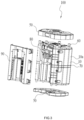
FIG. 3 is an exploded view of a battery pack according to an example; -
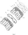
FIG. 4 is an exploded view of partial structures of a battery pack according to an example; -
FIG. 5 is an exploded view of a housing and cells according to an example; -
FIG. 6 is a cross-sectional view of a housing according to an example; -
FIG. 7 is a sectional view of a battery pack according to an example; and -
FIG. 8 is an exploded view of a terminal assembly in an example. - Before any examples of this application are explained in detail, it is to be understood that this application is not limited to its application to the structural details and the arrangement of components set forth in the following description or illustrated in the above drawings.
- In this application, the terms "comprising", "including", "having" or any other variation thereof are intended to cover an inclusive inclusion such that a process, method, article or device comprising a series of elements includes not only those series of elements, but also other elements not expressly listed, or elements inherent in the process, method, article, or device. Without further limitations, an element defined by the phrase "comprising a ..." does not preclude the presence of additional identical elements in the process, method, article, or device comprising that element.
- In this application, the term "and/or" is a kind of association relationship describing the relationship between associated objects, which means that there can be three kinds of relationships. For example, A and/or B can indicate that A exists alone, A and B exist simultaneously, and B exists alone. In addition, the character "/" in this application generally indicates that the contextual associated objects belong to an "and/or" relationship.
- In this application, the terms "connection", "combination", "coupling" and "installation" may be direct connection, combination, coupling or installation, and may also be indirect connection, combination, coupling or installation. Among them, for example, direct connection means that two members or assemblies are connected together without intermediaries, and indirect connection means that two members or assemblies are respectively connected with at least one intermediate members and the two members or assemblies are connected by the at least one intermediate members. In addition, "connection" and "coupling" are not limited to physical or mechanical connections or couplings, and may include electrical connections or couplings.
- In this application, it is to be understood by those skilled in the art that a relative term (such as "about", "approximately", and "substantially") used in conjunction with quantity or condition includes a stated value and has a meaning dictated by the context. For example, the relative term includes at least a degree of error associated with the measurement of a particular value, a tolerance caused by manufacturing, assembly, and use associated with the particular value, and the like. Such relative term should also be considered as disclosing the range defined by the absolute values of the two endpoints. The relative term may refer to plus or minus of a certain percentage (such as 1%, 5%, 10%, or more) of an indicated value. A value that did not use the relative term should also be disclosed as a particular value with a tolerance. In addition, "substantially" when expressing a relative angular position relationship (for example, substantially parallel, substantially perpendicular), may refer to adding or subtracting a certain degree (such as 1 degree, 5 degrees, 10 degrees or more) to the indicated angle.
- In this application, those skilled in the art will understand that a function performed by an assembly may be performed by one assembly, multiple assemblies, one member, or multiple members. Likewise, a function performed by a member may be performed by one member, an assembly, or a combination of members.
- In this application, the terms "up", "down", "left", "right", "front", and "rear" " and other directional words are described based on the orientation or positional relationship shown in the drawings, and should not be understood as limitations to the examples of this application. In addition, in this context, it also needs to be understood that when it is mentioned that an element is connected "above" or "under" another element, it can not only be directly connected "above" or "under" the other element, but can also be indirectly connected "above" or "under" the other element through an intermediate element. It should also be understood that orientation words such as upper side, lower side, left side, right side, front side, and rear side do not only represent perfect orientations, but can also be understood as lateral orientations. For example, lower side may include directly below, bottom left, bottom right, front bottom, and rear bottom.
- As an energy storage apparatus, a
battery pack 100 shown inFIGS. 1 to 3 can store electrical energy to supply power to an electronic device. In this example, the electronic device may include a large-sized outdoor moving device such as a riding mower and a snow thrower. Alternatively, the electronic device may include some energy conversion devices, such as an adapter or an inverter, capable of converting the electrical energy outputted by thebattery pack 100 so as to supply the power to other small-sized power tools such as handheld power tools and supply the power to some household electric devices such as a lamp, a mosquito-killing device, a fan, a cell phone, a computer, and other electric devices in daily lives. - In this example, the inner wall surface of a
housing 10 of thebattery pack 100 shown inFIGS. 1 to 7 extends to be capable of forming multiple accommodatingcavities 11. In this example, thehousing 10 is directly used for supportingcells 20, and theouter wall surface 10a of thehousing 10 is directly exposed to the external environment. In this example, eachaccommodating cavity 11 may be used for accommodating onecell 20. In some examples, one accommodatingcavity 11 may accommodatemultiple cells 20. In this example, the line connecting the centers ofcells 20 in any twoaccommodating cavities 11 may pass through the cavity walls of theaccommodating cavities 11. That is to say, there are cavity walls as blocks between any twoaccommodating cavities 11 so that any twoaccommodating cavities 11 cannot communicate with each other. - In this example, the
housing 10 directly supports thecells 20, which may be understood as the case where no other intermediate member capable of supporting acell 20 is disposed between anaccommodating cavity 11 formed by thehousing 10 and thecell 20, and the distance between the intra-cavity wall surface 11a of theaccommodating cavity 11 and at least part of the outerperipheral surface 20a of thecell 20 is greater than or equal to 0 mm and less than or equal to 1 mm. It is to be understood that when the distance between the intra-cavity wall surface 11a of theaccommodating cavity 11 and the at least part of the outerperipheral surface 20a of thecell 20 is greater than or equal to 0 mm and less than or equal to 1 mm, the outerperipheral surface 20a of thecorresponding cell 20 may be considered to be in contact with the intra-cavity wall surface 11a of theaccommodating cavity 11 substantially. In this way, the heat of thecell 20 can be directly transferred to the intra-cavity wall surface 11a of thehousing 10 and then dissipated to the outside through theouter wall surface 10a. For example, thecell 20 is a cylindrical cell, and theaccommodating cavity 11 is a cylindrical accommodating cavity adaptable to the cylindrical cell. The inner diameter of eachaccommodating cavity 11 is larger than or equal to the outer diameter of thecell 20, and the gap between the intra-cavity wall surface 11a of theaccommodating cavity 11 and the outerperipheral surface 20a of thecell 20 is very small. In some examples, thecell 20 may be square, and the correspondingaccommodating cavity 11 may also be square. - In an example, as shown in
FIG. 5 , the intra-cavity wall surface 11a of theaccommodating cavity 11 may be formed with a fitting rib 12. When thecell 20 is mounted to theaccommodating cavity 11, the fitting rib 12 can function as a guide and conducts the heat from thecell 20 directly to theaccommodating cavity 11 at the same time. In an example, a thermally-conductive flexible material may also be disposed between thecell 20 and the intra-cavity wall 11a so that the heat dissipation performance of thehousing 10 is improved. It is to be noted that even if a flexible heat dissipation material is disposed between thecell 20 and the intra-cavity wall 11a, thehousing 10 may also be considered to directly support thecell 20. The direct support in this example may be understood as the support of a hard structure to thecell 20. - In this example, the thermal conductivity of the
housing 10 is greater than or equal to 0.6 W/(m*k). For example, the thermal conductivity of thehousing 10 may be 0.6 W/(m*k), 0.7 W/(m*k), 0.8 W/(m*k), or 0.9 W/(m*k). - In this example, the
housing 10 is configured to have a cylindrical structure with two opposite end surfaces, where the multiple accommodatingcavities 11 are disposed in the cylindrical structure. The radial extension direction of theaccommodating cavity 11 substantially coincides with the mounting direction of thecell 20, and the end surfaces of the cylindrical structure may be substantially flush with two end surfaces of thecell 20 mounted in theaccommodating cavity 11. In this example, the shape of thecross section 13 of the cylindrical structure shown inFIG. 6 substantially coincides with the shape in which thecells 20 are arranged in thehousing 10. In this example, the shape of the connecting line of the tangent lines of the outer peripheral surfaces of outermost cells in the cylindrical structure substantially coincides with the shape of thecross section 13, that is to say, the connecting line of all the tangent lines of the outer peripheral surfaces of the outermost cells may form the outer wall surface of the cylindrical structure. In this example, thecross section 13 has a shape like a "crescent". In other examples, thecross section 13 may have a circular shape, a square shape, or other special shapes, which is not limited in this example. - In this example, the axial length of the
cell 20 is greater than or equal to 60 mm and less than or equal to 75 mm, and the diameter of the cross section of thecell 20 is greater than or equal to 15 mm and less than or equal to 25 mm. Accordingly, the axial length of thehousing 10 of the cylindrical structure is greater than or equal to 60 mm and less than or equal to 85 mm. In this example, the axial length of thehousing 10 is slightly greater than the axial length of thecell 20. - The area of the
cross section 13 of thehousing 10 is larger than or equal to 0.9 dm2 and smaller than or equal to 1.1 dm2. For example, the area of thecross section 13 may be 1 dm2. In this example, the ratio of the capacity of thebattery pack 100 to the area of thecross section 13 is higher than or equal to 8 Ah/dm2 and lower than or equal to 17 Ah/dm2. - In this example, since the
outer wall surface 10a of thehousing 10 is directly exposed to the external environment, thehousing 10 can directly conduct the heat of thebattery pack 100 into the air to dissipate the heat of thebattery pack 100. In this example, theouter wall surface 10a of thehousing 10 is a heat dissipation surface of the battery pack. A heat dissipation area of the heat dissipation surface is a surface area of theouter wall surface 10a. The heat dissipation area of the heat dissipation surface is larger than or equal to 4.5 dm2 and smaller than or equal to 7 dm2. For example, the heat dissipation area of the heat dissipation surface may be 5 dm2, 5.5 dm2, 6 dm2, or 7 dm2. The ratio of the capacity of thebattery pack 100 to the heat dissipation area of theouter wall surface 10a is higher than or equal to 1.2 Ah/dm2 and lower than or equal to 3.5 Ah/dm2. For example, the ratio of the capacity of thebattery pack 100 to the heat dissipation area of theouter wall surface 10a may be 1.5 Ah/dm2, 2 Ah/dm2, 2.5 Ah/dm2, or 3 Ah/dm2. In this example, heat dissipation requirements of thebattery pack 100 can be satisfied through the heat dissipation of thehousing 10, and thehousing 10 may be provided with no heat dissipation opening, or no heat dissipation fan may be disposed in thebattery pack 100. In this example, in order that the uniformity of the heat dissipation of thehousing 10 is ensured, the thickness from the inner wall surface of thehousing 10 to theouter wall surface 10a of thehousing 10 is substantially uniform. The thickness is greater than or equal to 1 mm and less than or equal to 5 mm. For example, the thickness may be 2 mm, 3 mm, or 4 mm. - The
housing 10 is generally plastic, and the heat dissipation performance of thebattery pack 100 is ensured because thehousing 10 accommodating or supporting thecells 20 is directly exposed to the external environment, but the overall strength of thebattery pack 100 may be affected. To enhance the overall strength of thebattery pack 100 and ensure the reliability of the heat dissipation performance, a metal insert (not shown) may be embedded in thehousing 10. The metal insert can enhance the strength of thehousing 10, and the thermal conductivity of a metal is better. In an example, the metal insert may be an aluminum alloy having a thickness of about 1 mm. - In this example, the
battery pack 100 further includes apanel assembly 30, anelectronic control assembly 40, and anend cover assembly 50. Thepanel assembly 30 may be attached to the two end surfaces of thehousing 10 to seal or insulate the positive and negative ends of thecell 20 mounted in theaccommodating cavity 11. In this example, thepanel assembly 30 may include insulation paper, a sealing sponge, a sealing gasket, or the like. The shape of thepanel assembly 30 substantially coincides with the shape of thecross section 13 of thehousing 10. Theelectronic control assembly 40 may be a circuit board mounted on thepanel assembly 30, where electronic elements disposed on the circuit board can be electrically connected to the positive or negative electrode of thecell 20. An element for collecting a cell parameter such as a voltage, a current, or a temperature may be disposed on the circuit board. A control element may also be disposed on the circuit board and can control the charging and discharging of thecell 20 according to the collected cell parameter. Theend cover assembly 50 covers theelectronic control assembly 40 and can seal thecells 20, thepanel assembly 30, and theelectronic control assembly 40 within thehousing 10. In this example, theend cover assembly 50 includes at least upper and lower end covers covering the two end surfaces of thehousing 10 separately. - In this example, the seal between the
cover plate assembly 50 and thehousing 10 may be implemented with a sealant. Thehousing 10 and thecover plate assembly 50 may be plastic members, where plastic molecules may be fused to each other through ultrasonic welding so that the seal between thehousing 10 and the cover plate is implemented. In an example, thepanel assembly 30, theelectronic control assembly 40, thehousing 10, and theend cover assembly 50 may also be sealingly connected to each other at joints through the ultrasonic welding. - As shown in
FIG. 7 , in order to ensure the stability of thebattery pack 100, multiple fixingmembers 60 may be used for connecting thepanel assembly 30, theelectronic control assembly 40, or thecover plate assembly 50 after penetrating through thehousing 10. In this example, as shown inFIGS. 4 to 6 , the multiple accommodatingcavities 11 in thehousing 10 are closely arranged, and ahole 61 through which a fixingmember 60 penetrates may be disposed in a gap formed through the arrangement of any two or moreaccommodating cavities 11. Thehole 61 through which the fixingmember 60 penetrates may also be disposed at the edge of thehousing 10 or another place so that the area of thecross section 13 is not increased. - In an example, one
housing 10 may accommodate a group ofcells 20. The number of groups ofcells 20 may be increased so that abattery pack 100 with a higher rated voltage is obtained. In an example, twohousings 10 each accommodate one group ofcells 20, and two groups of cells may be electrically connected to each other. For example, the rated voltage of one group of cells is 28 V, and the rated voltage of thebattery pack 100 constituted by the same two groups of cells is 56 V. The rated voltage of thebattery pack 100 may be higher than 56 V, and the number ofcells 20 or cell groups accommodated in the correspondinghousing 10 may be increased accordingly. As shown inFIGS. 1 to 4 , aconnector 70 may be disposed between the twohousings 10 accommodating the two groups of cells, where theconnector 70 may be a plastic member capable of providing electrical isolation between the two groups of cells. In an example, the upper and lower surfaces of theconnector 70 may be each provided with slots, and the slots can cover the lower end surface of onehousing 10 and the upper end surface of theother housing 10, thereby connecting the twohousings 10 together. In an example, plastic molecules may be fused to each other through technologies such as the ultrasonic welding and hot plate welding so that theconnector 70 and the twohousings 10 are sealingly connected. In an example, the fixingmember 60 may penetrate through theconnector 70 to fix the two groups of cells so that the overall strength and safety of thebattery pack 100 are increased. - As shown in
FIGS. 2 ,3 , and 9, thebattery pack 100 further includes aterminal assembly 80 mainly includingmultiple metal terminals 81 and aterminal block 82. Themetal terminals 81 are mounted on theterminal block 82, andpartitions 821 are disposed on theterminal block 82 so that themetal terminals 81 can be spaced apart from each other and there is a certain creepage distance between different metal terminals. Themetal terminal 81 may include at least a positive terminal, a negative terminal, and a communication terminal and can be connected to a corresponding connection terminal on a charger or a power tool such that the charging or discharging is performed. Typically, theterminal assembly 80 may be mounted in thehousing 10, and a grid which can correspond to each of themetal terminals 81 is reserved on thehousing 10 so that themetal terminals 81 are exposed to facilitate the connection of the charger or the power tool. However, there are certain safety hazards in the preceding method. For example, when the nominal voltage of thebattery pack 100 is relatively high, the metal terminals are easily short-circuited and the battery pack is damaged. - To solve the preceding problem, the
terminal assembly 80 may further include aterminal cover 83. Theterminal cover 83 is disposed on theterminal block 82 and is sealingly connected to theterminal block 82. In addition,grids 831 corresponding to themetal terminals 81 are disposed on theterminal cover 83 so that themetal terminals 81 can be exposed. The sealing connection may be understood as the sealing of the joint between the two components connected to each other. In addition to theoriginal partition 821, agrid 831 on theterminal cover 83 is also provided for eachmetal terminal 81. Therefore, the creepage distance betweenadjacent metal terminals 81 is increased. In an example, the creepage distance between themetal terminals 81 is greater than 8 mm and less than or equal to 20 mm. For example, the creepage distance between themetal terminals 81 may be 9 mm, 10 mm, 11 mm, 12 mm, 13 mm, 14 mm, 15 mm, 16 mm, 17 mm, 18 mm, 19 mm, or 20 mm. - In this example, the
terminal assembly 80 may be disposed on the outside of thehousing 10, and thehousing 10 is provided with a connection hole through which themetal terminal 81 can be electrically connected to a cell lead-out end on theelectronic control assembly 40 in thehousing 10. - In an example, to improve the stability of the connection between the
battery pack 100 and the tool, a mountinghousing 90 may be disposed on a side surface of thehousing 10, where the side surface may be inwardly recessed. In this example, theterminal assembly 80 is fixed to thehousing 10, and the mountinghousing 90 may be fixed to thehousing 10 by a connector such as a screw. In addition, the mountinghousing 90 is provided with an opening matched with the size of theterminal assembly 80. In an example, the mountinghousing 90 is further provided with a sliding groove which can guide thebattery pack 100 to be mounted to the tool. - In an example, as shown in
FIGS. 4 and5 , a side surface of thehousing 10 below the mountinghousing 90 may be open, where the side surface may be constituted by the inwardly-contracting extra-cavity wall surfaces 11b of the multiple accommodatingcavities 11. Anextra-cavity wall surface 11b is provided with agroove 11c which can improve the heat dissipation performance of thecell 20. - Different from battery packs in the existing art which are provided with cell brackets and housings, the battery pack in this example may be considered to be provided with no cell bracket, a cell bracket is directly used as part of the housing of the battery pack, or part of the housing of the battery pack constitutes a cell bracket. Thus, a layer of spacer (the housing) exists between the outside and part of cells in the cell assembly which are disposed at an edge. However, in the existing battery pack, at least two layers of spacers exist between cells and the outside, where one layer is a cell bracket, and the other layer is a housing. Therefore, with the design with no cell bracket in the present application, the heat dissipation performance of the battery pack can be greatly improved without the need to provide a heat dissipation opening.
- The basic principles, main features, and advantages of this application are shown and described above. It is to be understood by those skilled in the art that the aforementioned examples do not limit the present application in any form, and all technical solutions obtained through equivalent substitutions or equivalent transformations fall within the scope of the present application.
Claims (15)
- A battery pack (100) for supplying power to an electronic device, comprising:a housing (10) formed with a plurality of accommodating cavities (11); anda plurality of cells (20), wherein each cell among the plurality of cells has an outer peripheral surface (20a), and a distance between at least part of the outer peripheral surface and an intra-cavity wall surface (11a) of a respective accommodating cavity among the plurality of accommodating cavities is greater than or equal to 0 mm and less than or equal to 1 mm;wherein an outer wall surface (10a) of the housing is a heat dissipation surface, and a heat dissipation area of the heat dissipation surface is larger than or equal to 4.5 dm2 and smaller than or equal to 7 dm2.
- The battery pack according to claim 1, wherein a ratio of a capacity of the battery pack to the heat dissipation area is higher than or equal to 1.2 Ah/dm2 and lower than or equal to 3.5 Ah/dm2.
- The battery pack according to claim 1, wherein thermal conductivity of the housing is greater than or equal to 0.6 W/(m*k).
- The battery pack according to claim 1, wherein the housing is provided with no heat dissipation opening.
- The battery pack according to claim 1, wherein the housing has a cylindrical structure with the outer wall surface and two opposite end surfaces.
- The battery pack according to claim 5, further comprising: a panel assembly (30) disposed on one end surface of the cylindrical structure;an electronic control assembly (40) disposed on another end surface of the cylindrical structure; andan end cover assembly (50) covering the panel assembly or the electronic control assembly.
- The battery pack according to claim 6, further comprising a fixing member (60) configured to penetrate through and connect the end cover assembly, the panel assembly, the electronic control assembly, and the housing along a longitudinal extension direction of the cell.
- The battery pack according to claim 6, wherein the housing is fixed to at least one of the panel assembly and the electronic control assembly through ultrasonic welding.
- The battery pack according to claim 1, wherein a metal insert is disposed in the housing.
- The battery pack according to claim 1, wherein the intra-cavity wall surface is formed with a fitting rib.
- The battery pack according to claim 1, wherein the cell is a cylindrical cell, wherein an axial length of the cell is greater than or equal to 60 mm and less than or equal to 75 mm, and a diameter of a cross section of the cell is greater than or equal to 15 mm and less than or equal to 25 mm.
- The battery pack according to claim 1, wherein a distance from the intra-cavity wall surface to the outer wall surface is greater than or equal to 1 mm and less than or equal to 5 mm.
- The battery pack according to claim 1, further comprising a plurality of metal terminals (81) configured to be electrically connected to the plurality of cells and used for outputting electrical energy, wherein a creepage distance between metal terminals among the plurality of metal terminals is greater than 8 mm and less than or equal to 20 mm.
- The battery pack according to claim 13, further comprising a terminal block (82) on which the plurality of metal terminals are disposed and a terminal cover (83) provided with grids (831) corresponding to the plurality of metal terminals, wherein the terminal cover is sealingly connected to the terminal block.
- The battery pack according to claim 1, wherein the housing comprises at least two sub-housings which are independent, and the battery pack further comprises an intermediate member disposed between different ones of the at least two sub-housings and sealingly connected to the different sub-housings.
Applications Claiming Priority (1)
| Application Number | Priority Date | Filing Date | Title |
|---|---|---|---|
| CN202211231600 | 2022-10-08 |
Publications (1)
| Publication Number | Publication Date |
|---|---|
| EP4350839A1 true EP4350839A1 (en) | 2024-04-10 |
Family
ID=88021089
Family Applications (1)
| Application Number | Title | Priority Date | Filing Date |
|---|---|---|---|
| EP23197026.0A Pending EP4350839A1 (en) | 2022-10-08 | 2023-09-13 | Battery pack for supplying power to an electronic device |
Country Status (3)
| Country | Link |
|---|---|
| US (1) | US20240120593A1 (en) |
| EP (1) | EP4350839A1 (en) |
| CN (2) | CN117855719A (en) |
Families Citing this family (2)
| Publication number | Priority date | Publication date | Assignee | Title |
|---|---|---|---|---|
| DE202025103138U1 (en) | 2025-02-28 | 2025-07-07 | Lawnix Technology (Nanjing) Co., Ltd | Tool battery pack |
| DE202025103143U1 (en) | 2025-02-28 | 2025-07-18 | Lawnix Technology (Nanjing) Co., Ltd | Tool battery pack |
Citations (3)
| Publication number | Priority date | Publication date | Assignee | Title |
|---|---|---|---|---|
| US20140272517A1 (en) * | 2013-03-12 | 2014-09-18 | Milwaukee Electric Tool Corporation | Battery pack with heat sink |
| DE102017109919A1 (en) * | 2017-05-09 | 2018-11-15 | C. & E. Fein Gmbh | Battery Pack |
| WO2022118732A1 (en) * | 2020-12-03 | 2022-06-09 | 株式会社村田製作所 | Battery pack, electric tool, and electric vehicle |
Family Cites Families (9)
| Publication number | Priority date | Publication date | Assignee | Title |
|---|---|---|---|---|
| DE10106810A1 (en) * | 2001-02-14 | 2002-09-05 | Siemens Ag | Off-grid power supply unit |
| CN104752655B (en) * | 2013-12-31 | 2017-12-29 | 南京德朔实业有限公司 | Battery bag, charger and charging combination |
| DE102018222704A1 (en) * | 2018-12-21 | 2020-06-25 | Mahle International Gmbh | accumulator |
| KR102380443B1 (en) * | 2019-01-04 | 2022-03-29 | 주식회사 엘지에너지솔루션 | An energy storage system having a structure capable of distributing heat to adjacent battery modules |
| CN112490561A (en) * | 2019-08-23 | 2021-03-12 | 苏州宝时得电动工具有限公司 | Battery pack |
| EP4016709A4 (en) * | 2019-09-30 | 2024-05-29 | Makita Corporation | BATTERY PACK |
| WO2022226302A1 (en) * | 2021-04-23 | 2022-10-27 | Milwaukee Electric Tool Corporation | Conductive strap for battery pack |
| DE102021123312A1 (en) * | 2021-09-09 | 2023-03-09 | Audi Aktiengesellschaft | Battery assembly and method of providing a battery assembly |
| JP2024533358A (en) * | 2021-09-10 | 2024-09-12 | アイオンブロックス・インコーポレイテッド | Lithium-ion cells using high-rate electrolytes for cells using silicon oxide active materials to achieve high power discharge and long cycle life |
-
2023
- 2023-08-22 US US18/453,589 patent/US20240120593A1/en active Pending
- 2023-09-13 EP EP23197026.0A patent/EP4350839A1/en active Pending
- 2023-09-28 CN CN202311283191.2A patent/CN117855719A/en active Pending
- 2023-09-28 CN CN202311277327.9A patent/CN117855718A/en active Pending
Patent Citations (4)
| Publication number | Priority date | Publication date | Assignee | Title |
|---|---|---|---|---|
| US20140272517A1 (en) * | 2013-03-12 | 2014-09-18 | Milwaukee Electric Tool Corporation | Battery pack with heat sink |
| DE102017109919A1 (en) * | 2017-05-09 | 2018-11-15 | C. & E. Fein Gmbh | Battery Pack |
| WO2022118732A1 (en) * | 2020-12-03 | 2022-06-09 | 株式会社村田製作所 | Battery pack, electric tool, and electric vehicle |
| US20230207927A1 (en) * | 2020-12-03 | 2023-06-29 | Murata Manufacturing Co., Ltd. | Battery pack, electric tool, and electric vehicle |
Also Published As
| Publication number | Publication date |
|---|---|
| US20240120593A1 (en) | 2024-04-11 |
| CN117855719A (en) | 2024-04-09 |
| CN117855718A (en) | 2024-04-09 |
Similar Documents
| Publication | Publication Date | Title |
|---|---|---|
| JP5743356B2 (en) | Battery module and battery pack including the same | |
| EP4350839A1 (en) | Battery pack for supplying power to an electronic device | |
| CN104781949B (en) | power storage device | |
| JP7853276B2 (en) | power supply | |
| JP2019501477A (en) | Electrical energy storage module and manufacturing method thereof | |
| EP4086979A1 (en) | Battery, battery module, battery pack, and electric vehicle | |
| CN113067067B (en) | Single battery, battery module with single battery and power battery pack | |
| US20260081250A1 (en) | Battery and electrical apparatus | |
| CN217214989U (en) | Battery with a battery cell | |
| EP4310989B1 (en) | Battery module | |
| WO2024140426A1 (en) | Battery pack and external device | |
| US20220359930A1 (en) | Battery module and battery system | |
| CN218385679U (en) | Baffle, battery pack, energy storage storehouse and energy storage system | |
| KR102418597B1 (en) | Energy storage module | |
| CN110473706B (en) | Electric capacity electricity core module, electric capacity PACK | |
| CN119009298B (en) | Battery cells and their preparation processes, energy storage equipment | |
| CN218123554U (en) | Battery pack with heat dissipation structure | |
| CN219371279U (en) | Battery device | |
| US20260112786A1 (en) | Battery cell and process for forming the same | |
| CN219226546U (en) | Battery monomer, battery and power consumption device | |
| CN219371223U (en) | battery device | |
| CN219498103U (en) | Battery monomer, battery and power consumption device | |
| CN218677411U (en) | Electricity core supports heat dissipation casing | |
| CN222851616U (en) | Battery module and energy storage battery | |
| CN119361984A (en) | Battery cells and their preparation processes, energy storage equipment |
Legal Events
| Date | Code | Title | Description |
|---|---|---|---|
| PUAI | Public reference made under article 153(3) epc to a published international application that has entered the european phase |
Free format text: ORIGINAL CODE: 0009012 |
|
| STAA | Information on the status of an ep patent application or granted ep patent |
Free format text: STATUS: THE APPLICATION HAS BEEN PUBLISHED |
|
| AK | Designated contracting states |
Kind code of ref document: A1 Designated state(s): AL AT BE BG CH CY CZ DE DK EE ES FI FR GB GR HR HU IE IS IT LI LT LU LV MC ME MK MT NL NO PL PT RO RS SE SI SK SM TR |
|
| STAA | Information on the status of an ep patent application or granted ep patent |
Free format text: STATUS: REQUEST FOR EXAMINATION WAS MADE |
|
| 17P | Request for examination filed |
Effective date: 20241009 |
|
| RBV | Designated contracting states (corrected) |
Designated state(s): AL AT BE BG CH CY CZ DE DK EE ES FI FR GB GR HR HU IE IS IT LI LT LU LV MC ME MK MT NL NO PL PT RO RS SE SI SK SM TR |