EP4350720A1 - Superconducting rectangular wire material for superconducting coil, and superconducting coil - Google Patents
Superconducting rectangular wire material for superconducting coil, and superconducting coil Download PDFInfo
- Publication number
- EP4350720A1 EP4350720A1 EP22811329.6A EP22811329A EP4350720A1 EP 4350720 A1 EP4350720 A1 EP 4350720A1 EP 22811329 A EP22811329 A EP 22811329A EP 4350720 A1 EP4350720 A1 EP 4350720A1
- Authority
- EP
- European Patent Office
- Prior art keywords
- superconducting
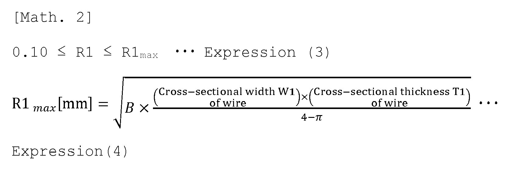
- wire
- rectangular wire
- resin layer
- radius
- Prior art date
- Legal status (The legal status is an assumption and is not a legal conclusion. Google has not performed a legal analysis and makes no representation as to the accuracy of the status listed.)
- Pending
Links
- 239000000463 material Substances 0.000 title claims abstract description 7
- 229920005989 resin Polymers 0.000 claims abstract description 137
- 239000011347 resin Substances 0.000 claims abstract description 137
- 230000002093 peripheral effect Effects 0.000 claims abstract description 20
- RYGMFSIKBFXOCR-UHFFFAOYSA-N Copper Chemical compound [Cu] RYGMFSIKBFXOCR-UHFFFAOYSA-N 0.000 claims abstract description 10
- 229910052802 copper Inorganic materials 0.000 claims abstract description 9
- 239000010949 copper Substances 0.000 claims abstract description 9
- 239000011248 coating agent Substances 0.000 claims abstract description 8
- 238000000576 coating method Methods 0.000 claims abstract description 8
- 229920001169 thermoplastic Polymers 0.000 claims abstract description 7
- 239000004416 thermosoftening plastic Substances 0.000 claims abstract description 7
- 229910000657 niobium-tin Inorganic materials 0.000 claims abstract description 5
- 239000011800 void material Substances 0.000 claims description 30
- 230000014509 gene expression Effects 0.000 claims description 25
- 238000004804 winding Methods 0.000 claims description 24
- 229920006287 phenoxy resin Polymers 0.000 claims description 7
- 239000013034 phenoxy resin Substances 0.000 claims description 7
- 229920001225 polyester resin Polymers 0.000 claims description 6
- 239000004645 polyester resin Substances 0.000 claims description 6
- 239000004962 Polyamide-imide Substances 0.000 claims description 5
- 229920006122 polyamide resin Polymers 0.000 claims description 5
- 229920002312 polyamide-imide Polymers 0.000 claims description 5
- 229920001721 polyimide Polymers 0.000 claims description 3
- 239000009719 polyimide resin Substances 0.000 claims description 3
- 229920005749 polyurethane resin Polymers 0.000 claims description 3
- 229920002554 vinyl polymer Polymers 0.000 claims description 3
- 239000010410 layer Substances 0.000 description 97
- 238000010791 quenching Methods 0.000 description 16
- 230000000171 quenching effect Effects 0.000 description 16
- 230000000052 comparative effect Effects 0.000 description 12
- 230000007423 decrease Effects 0.000 description 8
- 229920002292 Nylon 6 Polymers 0.000 description 7
- 238000000034 method Methods 0.000 description 7
- 239000002966 varnish Substances 0.000 description 6
- 230000008018 melting Effects 0.000 description 5
- 238000002844 melting Methods 0.000 description 5
- 239000007788 liquid Substances 0.000 description 4
- RLSSMJSEOOYNOY-UHFFFAOYSA-N m-cresol Chemical compound CC1=CC=CC(O)=C1 RLSSMJSEOOYNOY-UHFFFAOYSA-N 0.000 description 4
- 239000002904 solvent Substances 0.000 description 4
- 229920000571 Nylon 11 Polymers 0.000 description 3
- 239000004952 Polyamide Substances 0.000 description 3
- 238000004519 manufacturing process Methods 0.000 description 3
- 239000000203 mixture Substances 0.000 description 3
- 229920002647 polyamide Polymers 0.000 description 3
- 229920000299 Nylon 12 Polymers 0.000 description 2
- 229910000831 Steel Inorganic materials 0.000 description 2
- 239000011247 coating layer Substances 0.000 description 2
- 238000007765 extrusion coating Methods 0.000 description 2
- 230000020169 heat generation Effects 0.000 description 2
- 238000010438 heat treatment Methods 0.000 description 2
- 239000001307 helium Substances 0.000 description 2
- 229910052734 helium Inorganic materials 0.000 description 2
- SWQJXJOGLNCZEY-UHFFFAOYSA-N helium atom Chemical compound [He] SWQJXJOGLNCZEY-UHFFFAOYSA-N 0.000 description 2
- 238000005096 rolling process Methods 0.000 description 2
- 239000010959 steel Substances 0.000 description 2
- 239000000126 substance Substances 0.000 description 2
- 229920005992 thermoplastic resin Polymers 0.000 description 2
- 229920001187 thermosetting polymer Polymers 0.000 description 2
- 229910000881 Cu alloy Inorganic materials 0.000 description 1
- 229920002302 Nylon 6,6 Polymers 0.000 description 1
- 239000012300 argon atmosphere Substances 0.000 description 1
- 230000000694 effects Effects 0.000 description 1
- 238000001704 evaporation Methods 0.000 description 1
- 230000008020 evaporation Effects 0.000 description 1
- 238000001125 extrusion Methods 0.000 description 1
- 239000007789 gas Substances 0.000 description 1
- 238000009413 insulation Methods 0.000 description 1
- 229920005604 random copolymer Polymers 0.000 description 1
- 238000000926 separation method Methods 0.000 description 1
- 230000001629 suppression Effects 0.000 description 1
- 238000005491 wire drawing Methods 0.000 description 1
Images

Classifications
-
- H—ELECTRICITY
- H01—ELECTRIC ELEMENTS
- H01F—MAGNETS; INDUCTANCES; TRANSFORMERS; SELECTION OF MATERIALS FOR THEIR MAGNETIC PROPERTIES
- H01F6/00—Superconducting magnets; Superconducting coils
- H01F6/06—Coils, e.g. winding, insulating, terminating or casing arrangements therefor
-
- H—ELECTRICITY
- H01—ELECTRIC ELEMENTS
- H01B—CABLES; CONDUCTORS; INSULATORS; SELECTION OF MATERIALS FOR THEIR CONDUCTIVE, INSULATING OR DIELECTRIC PROPERTIES
- H01B12/00—Superconductive or hyperconductive conductors, cables, or transmission lines
- H01B12/02—Superconductive or hyperconductive conductors, cables, or transmission lines characterised by their form
- H01B12/04—Single wire
-
- H—ELECTRICITY
- H01—ELECTRIC ELEMENTS
- H01F—MAGNETS; INDUCTANCES; TRANSFORMERS; SELECTION OF MATERIALS FOR THEIR MAGNETIC PROPERTIES
- H01F5/00—Coils
- H01F5/06—Insulation of windings
-
- H—ELECTRICITY
- H01—ELECTRIC ELEMENTS
- H01F—MAGNETS; INDUCTANCES; TRANSFORMERS; SELECTION OF MATERIALS FOR THEIR MAGNETIC PROPERTIES
- H01F6/00—Superconducting magnets; Superconducting coils
- H01F6/02—Quenching; Protection arrangements during quenching
-
- H—ELECTRICITY
- H01—ELECTRIC ELEMENTS
- H01B—CABLES; CONDUCTORS; INSULATORS; SELECTION OF MATERIALS FOR THEIR CONDUCTIVE, INSULATING OR DIELECTRIC PROPERTIES
- H01B7/00—Insulated conductors or cables characterised by their form
- H01B7/02—Disposition of insulation
-
- Y—GENERAL TAGGING OF NEW TECHNOLOGICAL DEVELOPMENTS; GENERAL TAGGING OF CROSS-SECTIONAL TECHNOLOGIES SPANNING OVER SEVERAL SECTIONS OF THE IPC; TECHNICAL SUBJECTS COVERED BY FORMER USPC CROSS-REFERENCE ART COLLECTIONS [XRACs] AND DIGESTS
- Y02—TECHNOLOGIES OR APPLICATIONS FOR MITIGATION OR ADAPTATION AGAINST CLIMATE CHANGE
- Y02E—REDUCTION OF GREENHOUSE GAS [GHG] EMISSIONS, RELATED TO ENERGY GENERATION, TRANSMISSION OR DISTRIBUTION
- Y02E40/00—Technologies for an efficient electrical power generation, transmission or distribution
- Y02E40/60—Superconducting electric elements or equipment; Power systems integrating superconducting elements or equipment
Definitions
- the present disclosure relates to a superconducting rectangular wire for a superconducting coil and a superconducting coil.
- a superconducting wire exhibits superconducting performance at an extremely low temperature.
- a superconducting coil is obtained by winding such a superconducting wire around a winding frame.
- the superconducting wire has the advantage of being able to carry extremely large currents compared to an electric wire such as a normal copper wire, but when large currents are applied, large electromagnetic forces are generated, which may cause vibration and heat generation.
- the superconducting wire when the temperature rises due to such heat generation, even if a current smaller than the critical current value of the superconducting wire is supplied, the superconducting state breaks down to become a normal conduction state (hereinafter referred to as a "quenching"), and there is an issue that liquid helium evaporates at once. Therefore, a means for maintaining a superconducting state and preventing quenching has been awaited.
- Patent Document 1 discloses a superconducting coil including a winding frame and a superconducting wire wound around the winding frame.
- the superconducting coil of Patent Document 1 includes, between the winding frame and the superconducting wire, a first resin layer including a thermoplastic resin provided so as to surround the outer periphery of the superconducting wire; a second resin layer including a thermosetting resin disposed on the curved surface portion of the inner peripheral surface of the superconducting coil; and a mixed layer disposed between the first resin layer and the second resin layer and including a mixture of the thermoplastic resin and the thermosetting resin.
- Patent Document 1 there is an issue that, although the interfacial separation between members can be avoided, the occurrence of quenching due to insufficient adhesion between superconducting wires cannot be avoided.
- Patent Document 1 Japanese Patent No. 6276406
- a superconducting rectangular wire for a superconducting coil includes an NbTi-based or Nb 3 Sn-based wire having a surface coated with a copper-based material, and a fusible resin layer including a thermoplastic fusible resin and coating an outer peripheral surface of the wire.
- a radius of curvature (R2) of a corner portion of the fusible resin layer is equal to or less than a radius of curvature (R1) of a corner portion of the wire.
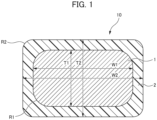
- FIG. 1 is a cross-sectional view showing an example of the superconducting rectangular wire for a superconducting coil according to the embodiment.
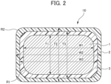
- FIG. 2 is a cross-sectional view showing another example of the superconducting rectangular wire for a superconducting coil according to the embodiment.
- a superconducting rectangular wire 10 includes a wire 1 and a fusible resin layer 2. As described later, the superconducting rectangular wire 10 is a member constituting a superconducting coil 50.
- the wire 1 constituting the superconducting rectangular wire 10 is an NbTi-based or Nb 3 Sn-based wire having a surface coated with a copper-based material.
- the copper-based material is copper or a copper alloy.
- the wire 1 is preferably a circular wire (round wire) or a rectangular wire, more preferably a rectangular wire.
- the wire 1 has such a shape, the void ratio of the superconducting coil can be reduced, and a large current density can be obtained. Furthermore, since the fused area (contact area) between the superconducting rectangular wires 10 is increased, the fused force can be increased.
- the wire 1 is a rectangular wire and the radius of curvature (R1) of the corner portion of the wire 1 in the cross section of the superconducting rectangular wire 10 is 0.10 mm or more and 0.40 mm or less.
- the wire 1 is a rectangular wire and the radius of curvature (R1) of the wire 1 is 0.10 mm or more, it is possible to prevent the wire 1 from getting caught between the wires 1 and causing scratches on the surface of the wire 1 when the wire 1 is wound.
- the wire 1 is a rectangular wire and the radius of curvature (R1) of the wire 1 is 0.40 mm or less, the void ratio of the superconducting coil can be reduced, so that quenching can be suppressed.
- the thickness T1 (short side) of the wire 1 is preferably 0.20 mm or more and 3.00 mm or less
- the width W1 (long side) of the wire 1 is preferably 0.40 mm or more and 10.00 mm or less.
- the fusible resin layer 2 constituting the superconducting rectangular wire 10 coats the outer peripheral surface of the wire 1.
- the fusible resin layers 2 include a thermoplastic fusible resin and are fused to each other by heating.
- the fusible resin layer 2 includes one or more resins selected from a phenoxy resin, a polyamide resin, or a polyester resin because the fusible resin layer 2 can be fused under low temperature conditions and good fused characteristics can be obtained.
- the phenoxy resin forming the fusible resin layer 2 is also called polyhydroxyether and has a molecular weight of 10000 or more, and has a structure represented by the following Formula (a).
- the phenoxy resin can be used as a varnish dissolved in a solvent such as m-cresol.
- the polyamide resin forming the fusible resin layer 2 is preferably a polyamide random copolymer having a relatively lower melting point than simple polyamide.
- a polyamide 6/polyamide 12 copolymer, a polyamide 6/polyamide 11 copolymer, and a polyamide 6/polyamide 66 copolymer are preferable, and among these, a polyamide 6/polyamide 12 copolymer and a polyamide 6/polyamide 11 copolymer are more preferable because of their low melting points.
- the melting point of the polyamide copolymer varies depending on the composition ratio of each resin, the composition ratio having the lowest melting point can be selected and used.
- the polyamide 6/polyamide 11 copolymer has the lowest melting point of 150°C when the polyamide 6 is 30 weight %.
- the polyamide resin can be used as a varnish dissolved in a solvent such as m-cresol.
- the average thickness of the fusible resin layer 2 is preferably 0.005 mm or more and 0.100 mm or less, and the lower limit is more preferably 0.010 mm or more, and the upper limit is more preferably 0.070 mm or less, and still more preferably 0.050 mm or less.
- the average thickness of the fusible resin layer 2 is 0.005 mm or more, the fusible resin is sufficiently present, so that the fused force is good.
- the average thickness of the fusible resin layer 2 is 0.100 mm or less, it is possible to suppress a decrease in the current density of the superconducting coil due to a decrease in the space factor of the wire.
- the average thickness of the fusible resin layer 2 is measured from the cross section of the superconducting rectangular wire 10.
- the superconducting rectangular wire 10 preferably further includes an insulating resin layer 3 including an insulating resin provided between the wire 1 and the fusible resin layer 2.
- the insulating resin layer 3 is provided between the outer peripheral surface of the wire 1 and the fusible resin layer 2.
- the insulating resin layer 3 preferably includes one or more resins selected from a polyvinyl formal resin, a polyamide-imide resin, a polyimide resin, a polyester resin, or a polyurethane resin.
- the lower limit of the average thickness of the insulating resin layer 3 is preferably 0.005 mm or more, more preferably 0.010 mm or more, and the upper limit is preferably 0.100 mm or less, more preferably 0.070 mm or less, still more preferably 0.050 mm or less.
- the average thickness of the insulating resin layer 3 is 0.005 mm or more, the insulating resin is sufficiently present, so that the insulating characteristics are good.
- the average thickness of the insulating resin layer 3 is 0.100 mm or less, a decrease in the current density of the superconducting coil due to a decrease in the space factor of the wire can be suppressed.
- the average thickness of the insulating resin layer 3 is measured from the cross section of the superconducting rectangular wire 10.
- W3 is the width (long side) of the wire 1 coated with the insulating resin layer 3 in the cross section of the superconducting rectangular wire 10.
- T3 is the thickness (short side) of the wire 1 coated with the insulating resin layer 3 in the cross section of the superconducting rectangular wire 10.
- the radius of curvature (R2) of the corner portion of the fusible resin layer 2 is equal to or less than the radius of curvature (R1) of the corner portion of the wire 1.
- the wire 1 is not a circular wire, for example, when the wire 1 is a rectangular wire as shown in FIGS. 1 and 2 , there are a plurality of corner portions of the wire 1 and a plurality of corner portions of the fusible resin layer 2 in the cross section of the superconducting rectangular wire 10.
- a corner portion of the wire 1 and a corner portion of the fusible resin layer 2 that are closest to each other are compared.
- the radius of curvature (R2) of a corner portion of the fusible resin layer 2 is equal to or less than the radius of curvature (R1) of a corner portion of the wire 1, the corner portion of the wire 1 being closest to the corner portion having the radius of curvature (R2) of the fusible resin layer 2.
- the radius of curvature (R2) of the corner portion of the fusible resin layer is larger than the radius of curvature (R1) of the corner portion of the wire.
- the radius of curvature (R2) of the surface of the corner portion of the fusible resin layer 2 is equal to or less than the radius of curvature (R1) of the surface of the corner portion of the wire 1.
- the radius of curvature (R2) of the fusible resin layer 2 is smaller than the radius of curvature (R1) of the wire 1, or the radius of curvature (R2) of the fusible resin layer 2 and the radius of curvature (R1) of the wire 1 are the same.
- the radius of curvature (R2) of the fusible resin layer 2 is equal to or less than the radius of curvature (R1) of the wire 1 in the cross section of the superconducting rectangular wire 10
- the radius of curvature of the outermost layer of the superconducting rectangular wire 10 can be made smaller than conventional art, so that the void ratio of the superconducting coil affected by the shape of the superconducting rectangular wire 10 can be reduced compared to conventional art, so that quenching can be suppressed.
- A is a first radius of curvature coefficient.
- A is preferably 0.06, and more preferably 0.04.
- W2 is the width (long side) of the superconducting rectangular wire 10 in the cross section of the superconducting rectangular wire 10, and is the width of the wire 1 coated with the fusible resin layer 2.
- T2 is the thickness (short side) of the superconducting rectangular wire 10 in the cross section of the superconducting rectangular wire 10, and is the thickness of the wire 1 coated with the fusible resin layer 2.
- W2 is preferably 0.10 mm or more and 5.00 mm or less, and more preferably 0.30 mm or more and 3.00 mm or less.
- T2 is preferably 0.10 mm or more and 5.00 mm or less, and more preferably 0.30 mm or more and 3.00 mm or less.
- R2 is preferably 0.01 mm or more, and more preferably 0.10 mm or more and 0.40 mm or less.
- B is a second radius of curvature coefficient.
- B is preferably 0.06, and more preferably 0.04.
- the wire 1 is a rectangular wire and the radius of curvature (R1) of the wire 1 is 0.10 mm or more, it is possible to prevent the wire 1 from getting caught between the wires 1 and causing scratches on the surface of the wire 1 when the wire 1 is wound.
- the wire 1 is a rectangular wire and the radius of curvature (R1) of the wire 1 is equal to or less than R1 max , the void ratio of the superconducting coil can be further reduced, so that quenching can be further suppressed.
- the outer peripheral surface of the rectangular wire is coated with a fusible resin layer.
- a liquid varnish is coated on the wire as the wire passes through the die, and then evaporation of the solvent in the varnish proceeds and curing of a part of the resin component proceeds depending on the type of the fusible resin in the furnace to form the fusible resin layer.
- the liquid varnish immediately after being coated spreads due to surface tension and is baked in this state, and as a result, the radius of curvature of the corner portion of the fusible resin layer becomes larger than the radius of curvature of the corner portion of the wire.
- the thickness of the fusible resin layer at the corner portion is smaller than the thickness of the fusible resin layer at the flat portion (other than the corner portion).
- the radius of curvature of the fusible resin layer which is the outermost layer, is larger than the radius of curvature of the wire, and as a result, it is difficult to largely reduce the void ratio in the superconducting coil.
- the method of coating the wire 1 with the fusible resin is not limited, but a method of coating the fusible resin by using a varnish obtained by dissolving a thermoplastic fusible resin in a solvent and baking the fusible resin on a round-shaped wire, and a method of coating the fusible resin by extrusion coating the surface of the round-shaped wire with the thermoplastic fusible resin are preferred.
- the rectangular-shaped superconducting rectangular wire 10 in which the radius of curvature (R2) of the corner portion of the fusible resin layer 2 is equal to or less than the radius of curvature (R1) of the corner portion of the wire 1 can be obtained.
- the amount of strain applied to the outer fusible resin layer 2 is larger than that applied to the wire 1 serving as a core, and as a result, the radius of curvature (R2) of the fusible resin layer 2 is equal to or less than the radius of curvature (R1) of the wire 1.
- the fusible resin layer 2 is coated on the outer peripheral surface of the wire 1 by extrusion coating the surface of the wire 1 with the fusible resin such that the radius of curvature (R2) of the fusible resin layer 2 is equal to or less than the radius of curvature (R1) of the wire 1.
- the superconducting rectangular wire 10 can be obtained.
- the radius of curvature (R2) of the corner portion of the fusible resin layer 2 which is the outermost layer largely depends on the radius of curvature of the corner portion of the die. Therefore, the radius of curvature (R2) of the fusible resin layer 2 can be adjusted to be small regardless of the radius of curvature (R1) of the corner portion of the wire 1.
- the superconducting rectangular wire 10 includes the insulating resin layer 3
- the superconducting rectangular wire 10 can be produced by coating the outer peripheral surface of the round-shaped wire or the wire 1 with the insulating resin layer 3 by an existing method and then applying the method described above using the round-shaped wire or the wire 1 including the insulating resin layer 3.
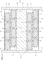
- FIG. 3 is a sectional view showing an example of the superconducting coil according to the embodiment.
- FIG. 4 is a sectional view showing another example of the superconducting coil according to the embodiment.
- FIGS. 3 and 4 are each a sectional view when the superconducting coil is cut along a plane including the axis of the winding frame.
- FIGS. 3 and 4 each show the superconducting coil 50 including the superconducting rectangular wire 10 that does not include the insulating resin layer 3.
- the structure is mainly the same except that the superconducting rectangular wire 10 is in one layer in FIG. 3 , and the superconducting rectangular wire 10 is in two layers (multilayer) in FIG. 4 .
- the superconducting coil 50 includes a winding frame 80 and a superconducting portion 60 including the superconducting rectangular wire 10 spirally wound around a body portion 81 of the winding frame 80.
- the void ratio of the superconducting portion 60 is 4.0% or less.
- the superconducting portion 60 includes one layer of the superconducting rectangular wire 10.
- the superconducting rectangular wire 10 is spirally wound around the body portion 81 from one flange portion 82 to the other flange portion 82 of the winding frame 80. At this time, a gap S1 may exist between the superconducting rectangular wire 10 and an inner surface 82a of the flange portion 82.
- a void V1 inner surface void
- a void V2 (outer surface void) may exist between a straight line L1 connecting the outer peripheral lines of all the superconducting rectangular wires 10 and two adjacent superconducting rectangular wires 10 (one superconducting rectangular wire 10) .
- the superconducting portion 60 includes a two-layer (multilayer) of the superconducting rectangular wire 10.
- the void V1 inner surface void
- the void V2 outer surface void
- the void V2 may exist between the superconducting rectangular wires 10 and the straight line L1 connecting the outer peripheral lines of all the superconducting rectangular wires 10 arranged in the outermost layer.
- a void V3 (internal void) may exist between the superconducting rectangular wires 10 in adjacent layers and between adjacent superconducting rectangular wires 10 in the same layer.
- a void V3 may exist between three superconducting rectangular wires 10 in adjacent layers and between adjacent superconducting rectangular wires 10 in the same layer.
- FIG. 4 an example in which the void V3 exists between three superconducting rectangular wires 10 is indicated, but the void V3 may exist between four superconducting rectangular wires 10.
- a void ratio V of the superconducting portion 60 constituting the superconducting coil 50 is a ratio of the total area of the voids V1, the voids V2, and the voids V3 to the value obtained by subtracting the area of the gaps S1 from the area S of two regions each formed by the outer peripheral line 81a of the body portion 81, the straight line L1 connecting the outer peripheral lines of all the superconducting rectangular wires 10 arranged in the outermost layer, and the inner surfaces 82a of the two flange portions 82.
- Void ratio V % of superconducting portion V1 + V2 + V3 ⁇ 100 / S ⁇ S1
- the superconducting rectangular wire 10 is wound around the winding frame 80 by spirally winding the superconducting rectangular wire 10 around the body portion 81 of the winding frame 80. Subsequently, by heating the winding frame 80 around which the superconducting rectangular wire 10 is wound in a reducing gas at a predetermined temperature and for a predetermined period of time, the superconducting coil 50 can be produced.
- the void ratio of the superconducting portion 60 is 4.0% or less, such a superconducting coil 50 can suppress quenching compared to conventional art.
- a polyamide-imide resin (Neoheat AlOOC, produced by Totoku Toryo Co., Ltd.) as an insulating resin was baked on an NbTi round wire having a surface coated with copper, and then a phenoxy resin (YP-50, produced by Nippon Steel Chemical & Materials Co., Ltd.) as a fusible resin was baked on the NbTi round wire. Subsequently, the wire coated with the insulating resin and the fusible resin was rolled to obtain the superconducting rectangular wire shown in Table 1.
- the superconducting rectangular wire was wound in 20 layers around a winding frame made of SUS304 and having a body diameter of 300 mm and a width of 500 mm, and then heated in an argon atmosphere at a temperature of 200°C for 120 minutes to obtain a superconducting coil.
- a superconducting coil was obtained in the same manner as in Example 1 except that the superconducting rectangular wire shown in Table 2 was wound in one layer around the winding frame in Example 1.
- a polyamide-imide resin (Neoheat AlOOC, produced by Totoku Toryo Co., Ltd.) as an insulating resin was baked on an NbTi rectangular wire having a surface coated with copper, and then a phenoxy resin (YP-50, produced by Nippon Steel Chemical & Materials Co., Ltd.) as a fusible resin was baked on the NbTi round wire to obtain the superconducting rectangular wire shown in Table 1. Subsequently, a superconducting coil was obtained in the same manner as in Example 1.
- a superconducting coil was obtained in the same manner as in Comparative Example 1 except that the superconducting rectangular wire shown in Table 2 was wound in one layer around the winding frame in Comparative Example 1.
- the superconducting coils obtained in the above Examples and Comparative Examples were cooled with liquid helium, and were repeatedly subjected to energization (current increase rate of 50 A/min) a plurality of times up to a current achieving a design magnetic field.
- Tables 1 and 2 show results of the maximum reachable magnetic field, the number of training quenches until the maximum reachable magnetic field is achieved, and the number of repetitions of heat cycle (normal temperature and 4K) until the reachable magnetic field decreases after the maximum reachable magnetic field is achieved.
Landscapes
- Engineering & Computer Science (AREA)
- Power Engineering (AREA)
- Superconductors And Manufacturing Methods Therefor (AREA)
Abstract
Description
- The present disclosure relates to a superconducting rectangular wire for a superconducting coil and a superconducting coil.
- A superconducting wire exhibits superconducting performance at an extremely low temperature. A superconducting coil is obtained by winding such a superconducting wire around a winding frame. The superconducting wire has the advantage of being able to carry extremely large currents compared to an electric wire such as a normal copper wire, but when large currents are applied, large electromagnetic forces are generated, which may cause vibration and heat generation. For the superconducting wire, when the temperature rises due to such heat generation, even if a current smaller than the critical current value of the superconducting wire is supplied, the superconducting state breaks down to become a normal conduction state (hereinafter referred to as a "quenching"), and there is an issue that liquid helium evaporates at once. Therefore, a means for maintaining a superconducting state and preventing quenching has been awaited.
- For example,
Patent Document 1 discloses a superconducting coil including a winding frame and a superconducting wire wound around the winding frame. The superconducting coil ofPatent Document 1 includes, between the winding frame and the superconducting wire, a first resin layer including a thermoplastic resin provided so as to surround the outer periphery of the superconducting wire; a second resin layer including a thermosetting resin disposed on the curved surface portion of the inner peripheral surface of the superconducting coil; and a mixed layer disposed between the first resin layer and the second resin layer and including a mixture of the thermoplastic resin and the thermosetting resin. - However, in the conventional art such as
Patent Document 1, there is an issue that, although the interfacial separation between members can be avoided, the occurrence of quenching due to insufficient adhesion between superconducting wires cannot be avoided. - Patent Document 1:
Japanese Patent No. 6276406 - It is an object of the present disclosure to provide a superconducting rectangular wire for a superconducting coil and a superconducting coil capable of suppressing quenching compared to conventional art.
-
- [1] A superconducting rectangular wire for a superconducting coil includes an NbTi-based or Nb3Sn-based wire having a surface coated with a copper-based material, and a fusible resin layer including a thermoplastic fusible resin and coating an outer peripheral surface of the wire, in which in a cross section of the superconducting rectangular wire for a superconducting coil, a radius of curvature (R2) of a corner portion of the fusible resin layer is equal to or less than a radius of curvature (R1) of a corner portion of the wire.
- [2] In the superconducting rectangular wire for a superconducting coil according to [1] above, the fusible resin layer has an average thickness of 0.005 mm or more and 0.100 mm or less.
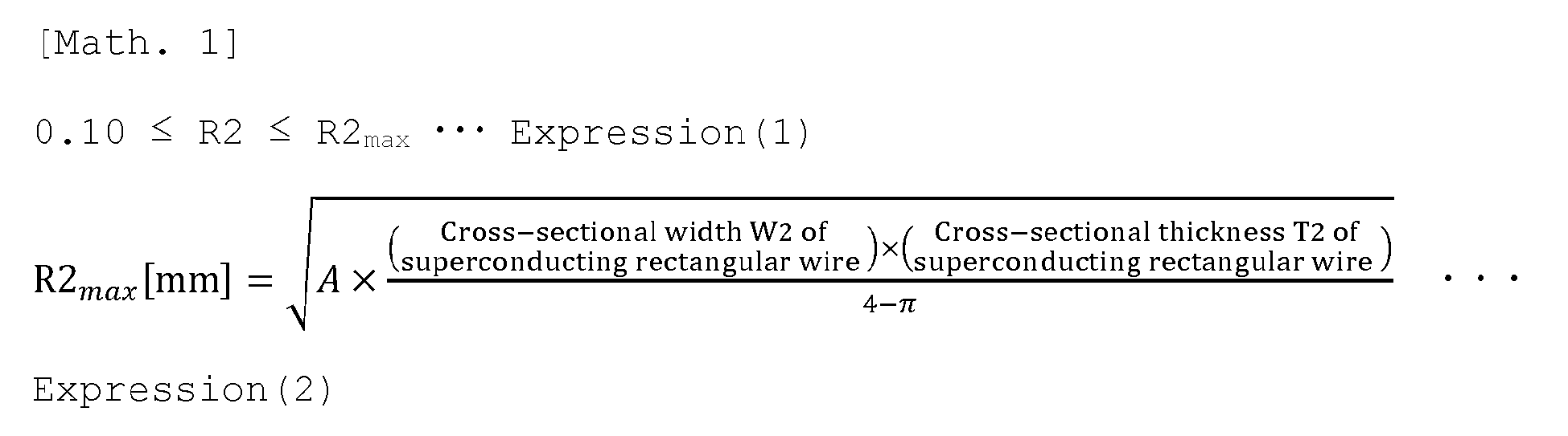
- [3] In the superconducting rectangular wire for a superconducting coil according to [1] or [2] above, in the cross section of the superconducting rectangular wire for a superconducting coil, the radius of curvature (R2) of the corner portion of the fusible resin layer satisfies the following Expressions (1) and (2):
- [4] In the superconducting rectangular wire for a superconducting coil according to any one of [1] to [3] above, the fusible resin layer includes one or more resins selected from a phenoxy resin, a polyamide resin, or a polyester resin.
- [5] The superconducting rectangular wire for a superconducting coil according to any one of [1] to [4] above further includes an insulating resin layer including an insulating resin provided between the wire and the fusible resin layer.
- [6] In the superconducting rectangular wire for a superconducting coil according to [5] above, the insulating resin layer includes one or more resins selected from a polyvinyl formal resin, a polyamide-imide resin, a polyimide resin, a polyester resin, or a polyurethane resin.
- [7] In the superconducting rectangular wire for a superconducting coil according to [5] or [6] above, the insulating resin layer has an average thickness of 0.005 mm or more and 0.100 mm or less.
- [8] In the superconducting rectangular wire for a superconducting coil according to any one of [1] to [7] above, the wire is a rectangular wire, and the radius of curvature (R1) of the corner portion of the wire is 0.10 mm or more and 0.40 mm or less.
- [9] In the superconducting rectangular wire for a superconducting coil according to any one of [1] to [8] above, the wire is a rectangular wire, and the radius of curvature (R1) of the corner portion of the wire satisfies the following Expressions (3) and (4):
- [10] A superconducting coil includes a winding frame, and a superconducting portion including the superconducting rectangular wire for a superconducting coil according to any one of [1] to [9] above, the superconducting rectangular wire being spirally wound around a body portion of the winding frame, in which the superconducting portion has a void ratio of 4.0% or less.
- According to the present disclosure, it is possible to provide a superconducting rectangular wire for a superconducting coil and a superconducting coil capable of suppressing quenching compared to conventional art.
-
-
FIG. 1 is a cross-sectional view showing an example of a superconducting rectangular wire for a superconducting coil according to an embodiment. -
FIG. 2 is a cross-sectional view showing another example of the superconducting rectangular wire for a superconducting coil according to the embodiment. -
FIG. 3 is a sectional view showing an example of a superconducting coil according to the embodiment. -
FIG. 4 is a sectional view showing another example of the superconducting coil according to the embodiment. - Hereinafter, an embodiment will be described in detail.
- As a result of extensive research, the present inventors have found that quenching can be suppressed compared to conventional art by controlling the shape of the cross section of each of a wire and a fusible resin layer constituting a superconducting rectangular wire for a superconducting coil, and have completed the present disclosure based on such findings.
- A superconducting rectangular wire for a superconducting coil according to the embodiment includes an NbTi-based or Nb3Sn-based wire having a surface coated with a copper-based material, and a fusible resin layer including a thermoplastic fusible resin and coating an outer peripheral surface of the wire. In a cross section of the superconducting rectangular wire for a superconducting coil, a radius of curvature (R2) of a corner portion of the fusible resin layer is equal to or less than a radius of curvature (R1) of a corner portion of the wire.
- First, the superconducting rectangular wire for a superconducting coil (hereinafter, also simply referred to as a superconducting rectangular wire) will be described.
FIG. 1 is a cross-sectional view showing an example of the superconducting rectangular wire for a superconducting coil according to the embodiment.FIG. 2 is a cross-sectional view showing another example of the superconducting rectangular wire for a superconducting coil according to the embodiment. A superconductingrectangular wire 10 includes awire 1 and afusible resin layer 2. As described later, the superconductingrectangular wire 10 is a member constituting asuperconducting coil 50. - The
wire 1 constituting the superconductingrectangular wire 10 is an NbTi-based or Nb3Sn-based wire having a surface coated with a copper-based material. The copper-based material is copper or a copper alloy. - From the viewpoint of suppressing the quenching of the superconducting coil, the
wire 1 is preferably a circular wire (round wire) or a rectangular wire, more preferably a rectangular wire. When thewire 1 has such a shape, the void ratio of the superconducting coil can be reduced, and a large current density can be obtained. Furthermore, since the fused area (contact area) between the superconductingrectangular wires 10 is increased, the fused force can be increased. - It is preferable that the
wire 1 is a rectangular wire and the radius of curvature (R1) of the corner portion of thewire 1 in the cross section of the superconductingrectangular wire 10 is 0.10 mm or more and 0.40 mm or less. When thewire 1 is a rectangular wire and the radius of curvature (R1) of thewire 1 is 0.10 mm or more, it is possible to prevent thewire 1 from getting caught between thewires 1 and causing scratches on the surface of thewire 1 when thewire 1 is wound. Furthermore, when thewire 1 is a rectangular wire and the radius of curvature (R1) of thewire 1 is 0.40 mm or less, the void ratio of the superconducting coil can be reduced, so that quenching can be suppressed. - As shown in
FIGS. 1 and2 , when thewire 1 is a rectangular wire, from the viewpoint of the winding property of thewire 1 and the suppression of quenching, in the cross section of the superconductingrectangular wire 10, the thickness T1 (short side) of thewire 1 is preferably 0.20 mm or more and 3.00 mm or less, and the width W1 (long side) of thewire 1 is preferably 0.40 mm or more and 10.00 mm or less. - The
fusible resin layer 2 constituting the superconductingrectangular wire 10 coats the outer peripheral surface of thewire 1. Thefusible resin layers 2 include a thermoplastic fusible resin and are fused to each other by heating. - It is preferable that the
fusible resin layer 2 includes one or more resins selected from a phenoxy resin, a polyamide resin, or a polyester resin because thefusible resin layer 2 can be fused under low temperature conditions and good fused characteristics can be obtained. - The phenoxy resin forming the
fusible resin layer 2 is also called polyhydroxyether and has a molecular weight of 10000 or more, and has a structure represented by the following Formula (a). The phenoxy resin can be used as a varnish dissolved in a solvent such as m-cresol.
- The polyamide resin forming the
fusible resin layer 2 is preferably a polyamide random copolymer having a relatively lower melting point than simple polyamide. For example, a polyamide 6/polyamide 12 copolymer, a polyamide 6/polyamide 11 copolymer, and a polyamide 6/polyamide 66 copolymer are preferable, and among these, a polyamide 6/polyamide 12 copolymer and a polyamide 6/polyamide 11 copolymer are more preferable because of their low melting points. - Since the melting point of the polyamide copolymer varies depending on the composition ratio of each resin, the composition ratio having the lowest melting point can be selected and used. For example, the polyamide 6/polyamide 11 copolymer has the lowest melting point of 150°C when the polyamide 6 is 30 weight %. The polyamide resin can be used as a varnish dissolved in a solvent such as m-cresol.
- The average thickness of the
fusible resin layer 2 is preferably 0.005 mm or more and 0.100 mm or less, and the lower limit is more preferably 0.010 mm or more, and the upper limit is more preferably 0.070 mm or less, and still more preferably 0.050 mm or less. When the average thickness of thefusible resin layer 2 is 0.005 mm or more, the fusible resin is sufficiently present, so that the fused force is good. When the average thickness of thefusible resin layer 2 is 0.100 mm or less, it is possible to suppress a decrease in the current density of the superconducting coil due to a decrease in the space factor of the wire. The average thickness of thefusible resin layer 2 is measured from the cross section of the superconductingrectangular wire 10. - As shown in
FIG. 2 , the superconductingrectangular wire 10 preferably further includes an insulatingresin layer 3 including an insulating resin provided between thewire 1 and thefusible resin layer 2. The insulatingresin layer 3 is provided between the outer peripheral surface of thewire 1 and thefusible resin layer 2. When the superconductingrectangular wire 10 includes the insulatingresin layer 3, the insulating property can be further improved. - From the viewpoint of good insulation of the electric flow from the
wire 1 to the outside, the insulatingresin layer 3 preferably includes one or more resins selected from a polyvinyl formal resin, a polyamide-imide resin, a polyimide resin, a polyester resin, or a polyurethane resin. - The lower limit of the average thickness of the insulating
resin layer 3 is preferably 0.005 mm or more, more preferably 0.010 mm or more, and the upper limit is preferably 0.100 mm or less, more preferably 0.070 mm or less, still more preferably 0.050 mm or less. When the average thickness of the insulatingresin layer 3 is 0.005 mm or more, the insulating resin is sufficiently present, so that the insulating characteristics are good. When the average thickness of the insulatingresin layer 3 is 0.100 mm or less, a decrease in the current density of the superconducting coil due to a decrease in the space factor of the wire can be suppressed. The average thickness of the insulatingresin layer 3 is measured from the cross section of the superconductingrectangular wire 10. - As shown in
FIGS. 1 and2 , W3 is the width (long side) of thewire 1 coated with the insulatingresin layer 3 in the cross section of the superconductingrectangular wire 10. T3 is the thickness (short side) of thewire 1 coated with the insulatingresin layer 3 in the cross section of the superconductingrectangular wire 10. - In the cross section of the superconducting
rectangular wire 10, the radius of curvature (R2) of the corner portion of thefusible resin layer 2 is equal to or less than the radius of curvature (R1) of the corner portion of thewire 1. When thewire 1 is not a circular wire, for example, when thewire 1 is a rectangular wire as shown inFIGS. 1 and2 , there are a plurality of corner portions of thewire 1 and a plurality of corner portions of thefusible resin layer 2 in the cross section of the superconductingrectangular wire 10. When there are a plurality of corner portions, a corner portion of thewire 1 and a corner portion of thefusible resin layer 2 that are closest to each other are compared. That is, the radius of curvature (R2) of a corner portion of thefusible resin layer 2 is equal to or less than the radius of curvature (R1) of a corner portion of thewire 1, the corner portion of thewire 1 being closest to the corner portion having the radius of curvature (R2) of thefusible resin layer 2. - For a conventional superconducting rectangular wire, in the cross section of the superconducting rectangular wire, the radius of curvature (R2) of the corner portion of the fusible resin layer is larger than the radius of curvature (R1) of the corner portion of the wire. On the other hand, for the superconducting
rectangular wire 10 according to the embodiment, as shown inFIGS. 1 and2 , in the cross section of the superconductingrectangular wire 10, the radius of curvature (R2) of the surface of the corner portion of thefusible resin layer 2 is equal to or less than the radius of curvature (R1) of the surface of the corner portion of thewire 1. In other words, for the superconductingrectangular wire 10, the radius of curvature (R2) of thefusible resin layer 2 is smaller than the radius of curvature (R1) of thewire 1, or the radius of curvature (R2) of thefusible resin layer 2 and the radius of curvature (R1) of thewire 1 are the same. - When the radius of curvature (R2) of the
fusible resin layer 2 is equal to or less than the radius of curvature (R1) of thewire 1 in the cross section of the superconductingrectangular wire 10, the radius of curvature of the outermost layer of the superconductingrectangular wire 10 can be made smaller than conventional art, so that the void ratio of the superconducting coil affected by the shape of the superconductingrectangular wire 10 can be reduced compared to conventional art, so that quenching can be suppressed. - In the cross section of the superconducting
rectangular wire 10, the radius of curvature of the corner portion of the superconductingrectangular wire 10, that is, the radius of curvature (R2) of the corner portion of thefusible resin layer 2 preferably satisfies the following Expressions (1) and (2) .
- In Expression (2), A is a first radius of curvature coefficient. A is preferably 0.06, and more preferably 0.04. As shown in
FIGS. 1 and2 , W2 is the width (long side) of the superconductingrectangular wire 10 in the cross section of the superconductingrectangular wire 10, and is the width of thewire 1 coated with thefusible resin layer 2. T2 is the thickness (short side) of the superconductingrectangular wire 10 in the cross section of the superconductingrectangular wire 10, and is the thickness of thewire 1 coated with thefusible resin layer 2. Specifically, W2 is preferably 0.10 mm or more and 5.00 mm or less, and more preferably 0.30 mm or more and 3.00 mm or less. T2 is preferably 0.10 mm or more and 5.00 mm or less, and more preferably 0.30 mm or more and 3.00 mm or less. - When the radius of curvature (R2) of the corner portion of the
fusible resin layer 2 satisfies the above Expressions (1) and (2), the void ratio of the superconducting coil can be further reduced, so that quenching can be further suppressed. For this reason, R2 is preferably 0.01 mm or more, and more preferably 0.10 mm or more and 0.40 mm or less. - It is preferable that the
wire 1 is a rectangular wire, and the radius of curvature (R1) of the corner portion of thewire 1 satisfies the following Expressions (3) and (4).
- In Expression (4), B is a second radius of curvature coefficient. B is preferably 0.06, and more preferably 0.04.
- When the
wire 1 is a rectangular wire and the radius of curvature (R1) of thewire 1 is 0.10 mm or more, it is possible to prevent thewire 1 from getting caught between thewires 1 and causing scratches on the surface of thewire 1 when thewire 1 is wound. When thewire 1 is a rectangular wire and the radius of curvature (R1) of thewire 1 is equal to or less than R1max, the void ratio of the superconducting coil can be further reduced, so that quenching can be further suppressed. - Next, a method for producing the superconducting
rectangular wire 10 will be described. - First, for comparison with the superconducting
rectangular wire 10 according to the embodiment, a method for producing a conventional superconducting rectangular wire in which the radius of curvature (R2) of the corner portion of the fusible resin layer is larger than the radius of curvature (R1) of the corner portion of the wire will be described. - In the conventional superconducting rectangular wire, by baking a fusible resin on the outer peripheral surface of the rectangular wire obtained by wire drawing, the outer peripheral surface of the rectangular wire is coated with a fusible resin layer. In the baking process, a liquid varnish is coated on the wire as the wire passes through the die, and then evaporation of the solvent in the varnish proceeds and curing of a part of the resin component proceeds depending on the type of the fusible resin in the furnace to form the fusible resin layer. At the corner portion of the wire, the liquid varnish immediately after being coated spreads due to surface tension and is baked in this state, and as a result, the radius of curvature of the corner portion of the fusible resin layer becomes larger than the radius of curvature of the corner portion of the wire. Furthermore, the thickness of the fusible resin layer at the corner portion is smaller than the thickness of the fusible resin layer at the flat portion (other than the corner portion). For the above reasons, the radius of curvature of the fusible resin layer, which is the outermost layer, is larger than the radius of curvature of the wire, and as a result, it is difficult to largely reduce the void ratio in the superconducting coil.
- On the other hand, as for the superconducting
rectangular wire 10 of the embodiment, the method of coating thewire 1 with the fusible resin is not limited, but a method of coating the fusible resin by using a varnish obtained by dissolving a thermoplastic fusible resin in a solvent and baking the fusible resin on a round-shaped wire, and a method of coating the fusible resin by extrusion coating the surface of the round-shaped wire with the thermoplastic fusible resin are preferred. - Subsequently, by rolling the round-shaped wire coated with the fusible resin into a rectangular shape, the rectangular-shaped superconducting
rectangular wire 10 in which the radius of curvature (R2) of the corner portion of thefusible resin layer 2 is equal to or less than the radius of curvature (R1) of the corner portion of thewire 1 can be obtained. In the rolling process, the amount of strain applied to the outerfusible resin layer 2 is larger than that applied to thewire 1 serving as a core, and as a result, the radius of curvature (R2) of thefusible resin layer 2 is equal to or less than the radius of curvature (R1) of thewire 1. - As for another method of producing the superconducting
rectangular wire 10, thefusible resin layer 2 is coated on the outer peripheral surface of thewire 1 by extrusion coating the surface of thewire 1 with the fusible resin such that the radius of curvature (R2) of thefusible resin layer 2 is equal to or less than the radius of curvature (R1) of thewire 1. Thus, the superconductingrectangular wire 10 can be obtained. In the case of extrusion molding, the radius of curvature (R2) of the corner portion of thefusible resin layer 2 which is the outermost layer largely depends on the radius of curvature of the corner portion of the die. Therefore, the radius of curvature (R2) of thefusible resin layer 2 can be adjusted to be small regardless of the radius of curvature (R1) of the corner portion of thewire 1. - In the case where the superconducting
rectangular wire 10 includes the insulatingresin layer 3, the superconductingrectangular wire 10 can be produced by coating the outer peripheral surface of the round-shaped wire or thewire 1 with the insulatingresin layer 3 by an existing method and then applying the method described above using the round-shaped wire or thewire 1 including the insulatingresin layer 3. - Next, the superconducting coil according to the embodiment will be described.
FIG. 3 is a sectional view showing an example of the superconducting coil according to the embodiment.FIG. 4 is a sectional view showing another example of the superconducting coil according to the embodiment.FIGS. 3 and4 are each a sectional view when the superconducting coil is cut along a plane including the axis of the winding frame.FIGS. 3 and4 each show thesuperconducting coil 50 including the superconductingrectangular wire 10 that does not include the insulatingresin layer 3. With reference toFIGS. 3 and4 , the structure is mainly the same except that the superconductingrectangular wire 10 is in one layer inFIG. 3 , and the superconductingrectangular wire 10 is in two layers (multilayer) inFIG. 4 . - As shown in
FIG. 3 , thesuperconducting coil 50 according to the embodiment includes a windingframe 80 and asuperconducting portion 60 including the superconductingrectangular wire 10 spirally wound around abody portion 81 of the windingframe 80. The void ratio of thesuperconducting portion 60 is 4.0% or less. Thesuperconducting portion 60 includes one layer of the superconductingrectangular wire 10. - The superconducting
rectangular wire 10 is spirally wound around thebody portion 81 from oneflange portion 82 to theother flange portion 82 of the windingframe 80. At this time, a gap S1 may exist between the superconductingrectangular wire 10 and aninner surface 82a of theflange portion 82. - In a section when the
superconducting coil 50 is cut along a plane including the axis of the winding frame 80 (hereinafter, also simply referred to as a section of the superconducting coil 50), with respect to the superconductingrectangular wires 10 that contact an outerperipheral line 81a of thebody portion 81, a void V1 (inner surface void) may exist between two adjacent superconducting rectangular wires 10 (one superconducting rectangular wire 10) and the outerperipheral line 81a of thebody portion 81. Furthermore, in the section of thesuperconducting coil 50, a void V2 (outer surface void) may exist between a straight line L1 connecting the outer peripheral lines of all the superconductingrectangular wires 10 and two adjacent superconducting rectangular wires 10 (one superconducting rectangular wire 10) . - In
FIG. 4 , thesuperconducting portion 60 includes a two-layer (multilayer) of the superconductingrectangular wire 10. With respect to the superconductingrectangular wires 10 at the innermost circumference that contact the outerperipheral line 81a of thebody portion 81, similarly to the above, the void V1 (inner surface void) may exist between the superconductingrectangular wires 10 and the outerperipheral line 81a. In addition, similarly to the above, in the section of thesuperconducting coil 50, the void V2 (outer surface void) may exist between the superconductingrectangular wires 10 and the straight line L1 connecting the outer peripheral lines of all the superconductingrectangular wires 10 arranged in the outermost layer. - Furthermore, a void V3 (internal void) may exist between the superconducting
rectangular wires 10 in adjacent layers and between adjacent superconductingrectangular wires 10 in the same layer. Here, as shown inFIG. 4 , an example in which the void V3 exists between three superconductingrectangular wires 10 is indicated, but the void V3 may exist between four superconductingrectangular wires 10. - In the section of the
superconducting coil 50, a void ratio V of thesuperconducting portion 60 constituting thesuperconducting coil 50 is a ratio of the total area of the voids V1, the voids V2, and the voids V3 to the value obtained by subtracting the area of the gaps S1 from the area S of two regions each formed by the outerperipheral line 81a of thebody portion 81, the straight line L1 connecting the outer peripheral lines of all the superconductingrectangular wires 10 arranged in the outermost layer, and theinner surfaces 82a of the twoflange portions 82.
- Next, a method for producing the
superconducting coil 50 will be described. - The superconducting
rectangular wire 10 is wound around the windingframe 80 by spirally winding the superconductingrectangular wire 10 around thebody portion 81 of the windingframe 80. Subsequently, by heating the windingframe 80 around which the superconductingrectangular wire 10 is wound in a reducing gas at a predetermined temperature and for a predetermined period of time, thesuperconducting coil 50 can be produced. - Since the void ratio of the
superconducting portion 60 is 4.0% or less, such asuperconducting coil 50 can suppress quenching compared to conventional art. - According to the embodiment described above, by producing the superconducting coil using the superconducting rectangular wire in which the shape of the cross section of each of the wire and the fusible resin layer is controlled, quenching can be suppressed compared to conventional art.
- Although the embodiment has been described, the present invention is not limited to the above embodiment, and includes all aspects included in the concept of the present disclosure and the scope of the claims, and may be variously modified within the scope of the present disclosure.
- Next, Examples and Comparative Examples will be described, but the present disclosure is not limited to these examples.
- A polyamide-imide resin (Neoheat AlOOC, produced by Totoku Toryo Co., Ltd.) as an insulating resin was baked on an NbTi round wire having a surface coated with copper, and then a phenoxy resin (YP-50, produced by Nippon Steel Chemical & Materials Co., Ltd.) as a fusible resin was baked on the NbTi round wire. Subsequently, the wire coated with the insulating resin and the fusible resin was rolled to obtain the superconducting rectangular wire shown in Table 1.
- Subsequently, the superconducting rectangular wire was wound in 20 layers around a winding frame made of SUS304 and having a body diameter of 300 mm and a width of 500 mm, and then heated in an argon atmosphere at a temperature of 200°C for 120 minutes to obtain a superconducting coil.
- A superconducting coil was obtained in the same manner as in Example 1 except that the superconducting rectangular wire shown in Table 2 was wound in one layer around the winding frame in Example 1.
- A polyamide-imide resin (Neoheat AlOOC, produced by Totoku Toryo Co., Ltd.) as an insulating resin was baked on an NbTi rectangular wire having a surface coated with copper, and then a phenoxy resin (YP-50, produced by Nippon Steel Chemical & Materials Co., Ltd.) as a fusible resin was baked on the NbTi round wire to obtain the superconducting rectangular wire shown in Table 1. Subsequently, a superconducting coil was obtained in the same manner as in Example 1.
- A superconducting coil was obtained in the same manner as in Comparative Example 1 except that the superconducting rectangular wire shown in Table 2 was wound in one layer around the winding frame in Comparative Example 1.
- The results of measuring the void ratio of the superconducting portion of each of the superconducting coils obtained in the above Examples and Comparative Examples are shown in Tables 1 and 2.
- Furthermore, the superconducting coils obtained in the above Examples and Comparative Examples were cooled with liquid helium, and were repeatedly subjected to energization (current increase rate of 50 A/min) a plurality of times up to a current achieving a design magnetic field. Tables 1 and 2 show results of the maximum reachable magnetic field, the number of training quenches until the maximum reachable magnetic field is achieved, and the number of repetitions of heat cycle (normal temperature and 4K) until the reachable magnetic field decreases after the maximum reachable magnetic field is achieved.
[Table 1] Example 1 Example 2 Example 3 Comparative Example 1 Comparative Example 2 Comparative Example 3 Wire Width W1 (mm) 2.28 1.69 1.30 2.27 1.67 1.31 Thickness T1 (mm) 1.26 1.08 1.10 1.27 1.07 1.11 Radius of curvature R1 (mm) 0.40 0.35 0.30 0.40 0.35 0.30 R 1 max (mm) 0.45 0.36 0.32 0.45 0.35 0.32 Insulating coating layer Average thickness (mm) 0.030 0.030 0.020 0.030 0.030 0.020 Width W3 (mm) 2.34 1.75 1.34 2.33 1.73 1.35 Thickness T3 (mm) 1.32 1.14 1.14 1.33 1.13 1.15 Radius of curvature R3 (mm) 0.39 0.33 0.29 0.43 0.38 0.32 Fusible coating layer Average thickness (mm) 0.035 0.035 0.025 0.035 0.035 0.025 Width W2 (mm) 2.41 1.82 1.39 2.40 1.80 1.40 Thickness T2 (mm) 1.39 1.21 1.19 1.40 1.20 1.20 Radius of curvature R2 (mm) 0.39 0.31 0.28 0.47 0.42 0.35 R2max (mm) 0.48 0.39 0.34 0.48 0.39 0.34 Superconducting coil Void ratio V 2.9% 2.7% 2.7% 4.4% 5.3% 4.4% Maximum reachable magnetic field/ design magnetic field 100% 100% 100% 80% 80% 85% Number of training quenches 1 0 0 10 7 6 Number of heat cycles until reachable magnetic field decreases (after training) ∞ ∞ ∞ 3 5 8 [Table 2] Example 4 Comparative Example 4 Wire Width W1 (mm) 1.69 1.67 Thickness T1 (mm) 1.08 1.07 Radius of curvature R1 (mm) 0.35 0.35 R 1 max (mm) 0.36 0.35 Insulating resin layer Average thickness (mm) 0.030 0.030 Width W3 (mm) 1.75 1.73 Thickness T3 (mm) 1.14 1.13 Radius of curvature R3 (mm) 0.33 0.38 Fusible resin layer Average thickness (mm) 0.035 0.035 Width W2 (mm) 1.82 1.80 Thickness T2 (mm) 1.21 1.20 Radius of curvature R2 (mm) 0.31 0.42 R2max (mm) 0.39 0.39 Superconducting coil Void ratio V 2.7% 5.3% Maximum reachable magnetic field/ design magnetic field 99% 79% Number of training quenches 1 8 Number of heat cycles until reachable magnetic field decreases (after training) ∞ 4 - As shown in Tables 1 and 2, in Examples 1 to 4, as a result of producing the superconducting coil using the superconducting rectangular wire in which the radius of curvature (R2) of the corner portion of the fusible resin layer is equal to or less than the radius of curvature (R1) of the corner portion of the wire in the cross section of the superconducting rectangular wire, the void ratio of the superconducting portion could be greatly reduced compared to conventional art, so that quenching could be suppressed. On the other hand, in Comparative Examples 1 to 4, as a result of producing the superconducting coil by using the superconducting rectangular wire in which the radius of curvature (R2) of the fusible resin layer is larger than the radius of curvature (R1) of the wire, the void ratio of the superconducting portion did not decrease and quenching could not be suppressed.
-
- 1 wire
- 2 fusible resin layer
- 3 insulating resin layer
- 10 superconducting rectangular wire for superconducting coil
- 50 superconducting coil
- 60 superconducting portion
- 80 winding frame
- 81 body portion of winding frame
- 81a outer peripheral line of body portion
- 82 flange portion
- 82a inner surface of flange portion
- T1 thickness of wire in cross section of superconducting rectangular wire
- T2 thickness of superconducting rectangular wire in cross section of superconducting rectangular wire (thickness of wire coated with fusible resin layer)
- T3 thickness of wire coated with insulating resin layer
- W1 width of wire in cross section of superconducting rectangular wire
- W2 width of superconducting rectangular wire in cross section of superconducting rectangular wire (width of wire coated with fusible resin layer)
- W3 width of wire coated with insulating resin layer
- V1, V2, V3 void
- S1 gap
Claims (10)
- A superconducting rectangular wire for a superconducting coil, comprising:an NbTi-based or Nb3Sn-based wire having a surface coated with a copper-based material; anda fusible resin layer including a thermoplastic fusible resin and coating an outer peripheral surface of the wire, whereinin a cross section of the superconducting rectangular wire for a superconducting coil, a radius of curvature (R2) of a corner portion of the fusible resin layer is equal to or less than a radius of curvature (R1) of a corner portion of the wire.
- The superconducting rectangular wire for a superconducting coil according to claim 1, wherein the fusible resin layer has an average thickness of 0.005 mm or more and 0.100 mm or less.
- The superconducting rectangular wire for a superconducting coil according to claim 1 or 2, wherein in the cross section of the superconducting rectangular wire for a superconducting coil, the radius of curvature (R2) of the corner portion of the fusible resin layer satisfies the following Expressions (1) and (2):

- The superconducting rectangular wire for a superconducting coil according to any one of claims 1 to 3, wherein the fusible resin layer includes one or more resins selected from a phenoxy resin, a polyamide resin, or a polyester resin.
- The superconducting rectangular wire for a superconducting coil according to any one of claims 1 to 4, further comprising an insulating resin layer including an insulating resin provided between the wire and the fusible resin layer.
- The superconducting rectangular wire for a superconducting coil according to claim 5, wherein the insulating resin layer includes one or more resins selected from a polyvinyl formal resin, a polyamide-imide resin, a polyimide resin, a polyester resin, or a polyurethane resin.
- The superconducting rectangular wire for a superconducting coil according to claim 5 or 6, wherein the insulating resin layer has an average thickness of 0.005 mm or more and 0.100 mm or less.
- The superconducting rectangular wire for a superconducting coil according to any one of claims 1 to 7, wherein the wire is a rectangular wire, and the radius of curvature (R1) of the corner portion of the wire is 0.10 mm or more and 0.40 mm or less.
- The superconducting rectangular wire for a superconducting coil according to any one of claims 1 to 8, wherein the wire is a rectangular wire, and the radius of curvature (R1) of the corner portion of the wire satisfies the following Expressions (3) and (4):

- A superconducting coil comprising:a winding frame; anda superconducting portion including the superconducting rectangular wire for a superconducting coil according to any one of claims 1 to 9, the superconducting rectangular wire being spirally wound around a body portion of the winding frame, whereinthe superconducting portion has a void ratio of 4.0% or less.
Applications Claiming Priority (2)
| Application Number | Priority Date | Filing Date | Title |
|---|---|---|---|
| JP2021088780 | 2021-05-26 | ||
| PCT/JP2022/021277 WO2022250059A1 (en) | 2021-05-26 | 2022-05-24 | Superconducting rectangular wire material for superconducting coil, and superconducting coil |
Publications (2)
| Publication Number | Publication Date |
|---|---|
| EP4350720A1 true EP4350720A1 (en) | 2024-04-10 |
| EP4350720A4 EP4350720A4 (en) | 2025-05-07 |
Family
ID=84228839
Family Applications (1)
| Application Number | Title | Priority Date | Filing Date |
|---|---|---|---|
| EP22811329.6A Pending EP4350720A4 (en) | 2021-05-26 | 2022-05-24 | SUPERCONDUCTING RECTANGULAR WIRE MATERIAL FOR SUPERCONDUCTING COIL AND SUPERCONDUCTING COIL |
Country Status (5)
| Country | Link |
|---|---|
| US (1) | US20240249866A1 (en) |
| EP (1) | EP4350720A4 (en) |
| JP (1) | JPWO2022250059A1 (en) |
| CN (1) | CN117321707A (en) |
| WO (1) | WO2022250059A1 (en) |
Family Cites Families (11)
| Publication number | Priority date | Publication date | Assignee | Title |
|---|---|---|---|---|
| JPS59105710U (en) * | 1982-12-30 | 1984-07-16 | 住友重機械工業株式会社 | superconducting wire |
| JPH0684661A (en) * | 1992-09-01 | 1994-03-25 | Toshiba Corp | Self-fusible coating superconducting coil |
| JPH08172013A (en) * | 1994-10-04 | 1996-07-02 | Toshiba Corp | Superconducting coil, method of manufacturing the same, and superconducting wire |
| JP2000113746A (en) * | 1998-10-02 | 2000-04-21 | Kobe Steel Ltd | Manufacturing method of rectangular insulated superconducting wire |
| JP5196532B2 (en) * | 2007-11-13 | 2013-05-15 | 株式会社日本自動車部品総合研究所 | Flat wire |
| JP5137749B2 (en) * | 2008-08-28 | 2013-02-06 | 古河電気工業株式会社 | Insulated wire for winding and method of manufacturing coil |
| EP3159899A4 (en) | 2014-06-18 | 2018-03-21 | Hitachi, Ltd. | Super-conducting wire, super-conducting coil, and magnetic resonance imaging device |
| JP5778332B1 (en) * | 2014-12-26 | 2015-09-16 | 古河電気工業株式会社 | Insulated wires with excellent bending resistance, coils and electronic / electric equipment using them |
| JP6373309B2 (en) * | 2016-07-19 | 2018-08-15 | 古河電気工業株式会社 | Insulated wires, coils and electrical / electronic equipment |
| EP3514803B1 (en) * | 2016-09-13 | 2023-08-02 | Essex Furukawa Magnet Wire Japan Co., Ltd. | Insulated wire, coil, and electrical or electronic equipment |
| WO2021100789A1 (en) * | 2019-11-18 | 2021-05-27 | 古河電気工業株式会社 | Superconducting coil, method for producing same, and rectangular superconducting wire material for superconducting coil |
-
2022
- 2022-05-24 WO PCT/JP2022/021277 patent/WO2022250059A1/en not_active Ceased
- 2022-05-24 US US18/564,086 patent/US20240249866A1/en active Pending
- 2022-05-24 EP EP22811329.6A patent/EP4350720A4/en active Pending
- 2022-05-24 JP JP2023523492A patent/JPWO2022250059A1/ja active Pending
- 2022-05-24 CN CN202280035816.0A patent/CN117321707A/en active Pending
Also Published As
| Publication number | Publication date |
|---|---|
| JPWO2022250059A1 (en) | 2022-12-01 |
| CN117321707A (en) | 2023-12-29 |
| WO2022250059A1 (en) | 2022-12-01 |
| EP4350720A4 (en) | 2025-05-07 |
| US20240249866A1 (en) | 2024-07-25 |
Similar Documents
| Publication | Publication Date | Title |
|---|---|---|
| EP1096580B1 (en) | Oxide superconducting wire having insulating coat and production method thereof | |
| US11615914B2 (en) | Magnet wire with thermoplastic insulation | |
| WO2019188777A1 (en) | Insulated electric wire material, method for manufacturing insulated electric wire material, coil, and electric/electronic device | |
| JP2025066827A (en) | Superconducting coil and method for manufacturing the same, and superconducting flat wire rod for superconducting coil | |
| JPS6356648B2 (en) | ||
| US6525272B2 (en) | Multilayer insulated wire and transformer using the same | |
| US20260088202A1 (en) | Aluminum-carbon nanotube metal matrix composite magnet wires | |
| US20240249866A1 (en) | Superconducting rectangular wire for superconducting coil, and superconducting coil | |
| US20100248969A1 (en) | Oxide superconducting wire, superconducting structure, method of producing oxide superconducting wire, superconducting cable, superconducting magnet, and product incorporating superconducting magnet | |
| JP2015011861A (en) | Solderable insulated wire and manufacturing method thereof | |
| JP5117166B2 (en) | NbTi superconducting multi-core wire for pulse and NbTi superconducting molded stranded wire for pulse | |
| JP4737094B2 (en) | Oxide superconducting wire, superconducting structure, manufacturing method of oxide superconducting wire, superconducting cable, superconducting magnet, and product including superconducting magnet | |
| US6141860A (en) | Method for manufacturing coil | |
| WO2024075827A1 (en) | Superconducting wire material for superconducting coil, and superconducting coil | |
| JPH03184214A (en) | Self-fusion-type aggregate cable and its manufacture | |
| JP4697240B2 (en) | Manufacturing method of Nb3Sn superconducting wire | |
| KR20230002294A (en) | heat-resistant insulated wire | |
| JP7850091B2 (en) | Flat rectangular molded stranded wire and its manufacturing method | |
| US20240274327A1 (en) | Precursor wire for compound superconducting wire, compound superconducting wire, and rewinding method for compound superconducting wire | |
| JP5170897B2 (en) | Flat superconducting molded stranded wire and method for manufacturing the same | |
| EP4227427A1 (en) | Nbti superconducting multi-core wire | |
| JPH01251517A (en) | Superconductive stranded wire and manufacture thereof | |
| JP2000113746A (en) | Manufacturing method of rectangular insulated superconducting wire | |
| JPH07141939A (en) | Low AC loss NbTi superconducting twisted wire manufacturing method | |
| JP2021048008A (en) | Magnet wire, and method for manufacturing magnet wire |
Legal Events
| Date | Code | Title | Description |
|---|---|---|---|
| STAA | Information on the status of an ep patent application or granted ep patent |
Free format text: STATUS: THE INTERNATIONAL PUBLICATION HAS BEEN MADE |
|
| PUAI | Public reference made under article 153(3) epc to a published international application that has entered the european phase |
Free format text: ORIGINAL CODE: 0009012 |
|
| STAA | Information on the status of an ep patent application or granted ep patent |
Free format text: STATUS: REQUEST FOR EXAMINATION WAS MADE |
|
| 17P | Request for examination filed |
Effective date: 20231205 |
|
| AK | Designated contracting states |
Kind code of ref document: A1 Designated state(s): AL AT BE BG CH CY CZ DE DK EE ES FI FR GB GR HR HU IE IS IT LI LT LU LV MC MK MT NL NO PL PT RO RS SE SI SK SM TR |
|
| DAV | Request for validation of the european patent (deleted) | ||
| DAX | Request for extension of the european patent (deleted) | ||
| A4 | Supplementary search report drawn up and despatched |
Effective date: 20250409 |
|
| RIC1 | Information provided on ipc code assigned before grant |
Ipc: H01B 12/04 20060101ALI20250403BHEP Ipc: H01B 7/02 20060101ALI20250403BHEP Ipc: H01F 6/06 20060101AFI20250403BHEP |