EP4350626A1 - Image processing system, method for controlling the same, and program - Google Patents
Image processing system, method for controlling the same, and program Download PDFInfo
- Publication number
- EP4350626A1 EP4350626A1 EP23201422.5A EP23201422A EP4350626A1 EP 4350626 A1 EP4350626 A1 EP 4350626A1 EP 23201422 A EP23201422 A EP 23201422A EP 4350626 A1 EP4350626 A1 EP 4350626A1
- Authority
- EP
- European Patent Office
- Prior art keywords
- parts
- processing system
- image processing
- identifier
- extracted
- Prior art date
- Legal status (The legal status is an assumption and is not a legal conclusion. Google has not performed a legal analysis and makes no representation as to the accuracy of the status listed.)
- Granted
Links
Images




Classifications
-
- G—PHYSICS
- G06—COMPUTING OR CALCULATING; COUNTING
- G06T—IMAGE DATA PROCESSING OR GENERATION, IN GENERAL
- G06T17/00—Three-dimensional [3D] modelling for computer graphics
-
- G—PHYSICS
- G06—COMPUTING OR CALCULATING; COUNTING
- G06T—IMAGE DATA PROCESSING OR GENERATION, IN GENERAL
- G06T7/00—Image analysis
- G06T7/20—Analysis of motion
- G06T7/246—Analysis of motion using feature-based methods, e.g. the tracking of corners or segments
-
- H—ELECTRICITY
- H04—ELECTRIC COMMUNICATION TECHNIQUE
- H04N—PICTORIAL COMMUNICATION, e.g. TELEVISION
- H04N13/00—Stereoscopic video systems; Multi-view video systems; Details thereof
- H04N13/10—Processing, recording or transmission of stereoscopic or multi-view image signals
- H04N13/106—Processing image signals
- H04N13/111—Transformation of image signals corresponding to virtual viewpoints, e.g. spatial image interpolation
- H04N13/117—Transformation of image signals corresponding to virtual viewpoints, e.g. spatial image interpolation the virtual viewpoint locations being selected by the viewers or determined by viewer tracking
-
- G—PHYSICS
- G06—COMPUTING OR CALCULATING; COUNTING
- G06T—IMAGE DATA PROCESSING OR GENERATION, IN GENERAL
- G06T7/00—Image analysis
- G06T7/20—Analysis of motion
-
- G—PHYSICS
- G06—COMPUTING OR CALCULATING; COUNTING
- G06T—IMAGE DATA PROCESSING OR GENERATION, IN GENERAL
- G06T7/00—Image analysis
- G06T7/70—Determining position or orientation of objects or cameras
-
- G—PHYSICS
- G06—COMPUTING OR CALCULATING; COUNTING
- G06V—IMAGE OR VIDEO RECOGNITION OR UNDERSTANDING
- G06V10/00—Arrangements for image or video recognition or understanding
- G06V10/20—Image preprocessing
- G06V10/25—Determination of region of interest [ROI] or a volume of interest [VOI]
-
- H—ELECTRICITY
- H04—ELECTRIC COMMUNICATION TECHNIQUE
- H04N—PICTORIAL COMMUNICATION, e.g. TELEVISION
- H04N13/00—Stereoscopic video systems; Multi-view video systems; Details thereof
- H04N13/20—Image signal generators
- H04N13/275—Image signal generators from three-dimensional [3D] object models, e.g. computer-generated stereoscopic image signals
-
- H—ELECTRICITY
- H04—ELECTRIC COMMUNICATION TECHNIQUE
- H04N—PICTORIAL COMMUNICATION, e.g. TELEVISION
- H04N13/00—Stereoscopic video systems; Multi-view video systems; Details thereof
- H04N13/20—Image signal generators
- H04N13/282—Image signal generators for generating image signals corresponding to three or more geometrical viewpoints, e.g. multi-view systems
-
- G—PHYSICS
- G06—COMPUTING OR CALCULATING; COUNTING
- G06T—IMAGE DATA PROCESSING OR GENERATION, IN GENERAL
- G06T2207/00—Indexing scheme for image analysis or image enhancement
- G06T2207/30—Subject of image; Context of image processing
- G06T2207/30196—Human being; Person
-
- G—PHYSICS
- G06—COMPUTING OR CALCULATING; COUNTING
- G06V—IMAGE OR VIDEO RECOGNITION OR UNDERSTANDING
- G06V2201/00—Indexing scheme relating to image or video recognition or understanding
- G06V2201/07—Target detection
Definitions
- the present invention relates to an image processing system that generates a virtual viewpoint image, a method for controlling an image processing system, and a program.
- a virtual viewpoint image generation system that generates a virtual viewpoint image, which is an image viewed from a virtual viewpoint designated by a user, based on images captured by an image capturing system including a plurality of cameras.
- Japanese Patent Application Laid-open No. 2017-211828 discusses a system in which images captured by a plurality of cameras are transmitted to an image computing server (an image processing apparatus) and then the image processing apparatus extracts, from the captured images, a region with a large change as a foreground image, and a region with a small change as a background image.
- VR virtual reality
- HMD head mounted display
- 3DCG three-dimensional computer graphics
- an image processing system as specified in claims 1 to 17.
- a method for controlling an image processing system as specified in claim 18 According to a third aspect of the present invention, there is provided a program for causing a computer to perform a method for controlling an image processing system as specified in claim 19.
- Fig. 1 illustrates an example of a configuration of an image processing system that generates a virtual viewpoint image according to a first embodiment of the present invention.
- the image processing system includes a plurality of image capturing units 1, a synchronization unit 2, a three-dimensional shape estimation unit 3, an accumulation unit 4, a viewpoint designation unit 5, an image generation unit 6, a display unit 7, a sound collection unit 8, a sound signal generation unit 9, a sound output unit 10, a shape extraction unit 11, a tracking unit 12, an object position calculation unit 13, and an identifier setting unit 14.
- the image processing system may include one image processing apparatus or a plurality of image processing apparatuses. In the following description, a case will be described where the image processing system includes one image processing apparatus.
- the plurality of image capturing units 1 captures images in synchronization with each other based on a synchronization signal from the synchronization unit 2.
- the image capturing units 1 are video cameras that capture images as video data comprising a plurality of frames.
- the image capturing units 1 output the captured images to the three-dimensional shape estimation unit 3.
- the image capturing units 1 are arranged around an image capturing region including an object in order to enable capturing the images of the object from a plurality of directions.
- the three-dimensional shape estimation unit 3 extracts, for example, a silhouette of the object using the input captured images viewed from a plurality of viewpoints, and generates a three-dimensional shape of the object using a volume intersection method or the like.
- the three-dimensional shape estimation unit 3 outputs the generated three-dimensional shape of the object and the captured images to the accumulation unit 4.
- the object is a three-dimensional shape generation target, and examples of the object include a person and an article used by a person.
- the sound collection unit 8 collects sounds at a plurality of positions in the image capturing region or a sound from each object, and outputs data of the collected sounds to the accumulation unit 4.
- the accumulation unit 4 stores and accumulates the following data group as data (material data) used to generate a virtual viewpoint image. More specifically, the data used to generate a virtual viewpoint image includes the captured images and the three-dimensional shape of the object that are input from the three-dimensional shape estimation unit 3. The data used to generate a virtual viewpoint image also includes camera parameters, such as the position, orientation and optical characteristics of each of the image capturing units 1, and the sound data obtained by the sound collection unit 8. In addition, a background model and a background texture image are stored (recorded) in advance in the accumulation unit 4, as data used to generate the background of the virtual viewpoint image.
- the viewpoint designation unit 5 includes a viewpoint operation unit that is a physical user interface, such as a joy stick or a jog dial (not illustrated), and a display unit for displaying the virtual viewpoint image.
- a viewpoint operation unit that is a physical user interface, such as a joy stick or a jog dial (not illustrated)
- a display unit for displaying the virtual viewpoint image.
- the virtual viewpoint of the virtual viewpoint image displayed on the display unit can be changed by the viewpoint operation unit.
- the virtual viewpoint image is generated as appropriate by the image generation unit 6 (described below) and displayed on the display unit.
- the viewpoint designation unit 5 may use the display unit 7 (described below) as the display unit, or may include the display unit separately.
- the viewpoint designation unit 5 generates virtual viewpoint information based on the input from the viewpoint operation unit, and outputs the generated virtual viewpoint information to the image generation unit 6.
- the virtual viewpoint information includes information corresponding to external camera parameters, such as the position and orientation of the virtual viewpoint, information corresponding to internal camera parameters, such as a focal length and an angle of view, and time information designating an image capturing time of the image to be reproduced.
- the image generation unit 6 obtains the material data corresponding to the designated image capturing time from the accumulation unit 4, based on the time information included in the input virtual viewpoint information.
- the image generation unit 6 generates the virtual viewpoint image based on the set virtual viewpoint, using the captured images and the three-dimensional shape of the object included in the obtained material data, and outputs the generated virtual viewpoint image to the display unit 7.
- the display unit 7 displays the image input from the image generation unit 6.
- the display unit 7 is, for example, a display or a head-mounted display (HMD).
- HMD head-mounted display
- the sound signal generation unit 9 obtains the sound data corresponding to the designated image capturing time from the accumulation unit 4, based on the time information included in the input virtual viewpoint information.
- the sound signal generation unit 9 arranges, on a three-dimensional space, the obtained sound data as a virtual sound source.
- the sound signal generation unit 9 generates a sound signal based on the distance in position between the virtual sound source and the virtual viewpoint and the direction of the virtual viewpoint, and outputs the generated sound signal to the sound output unit 10.
- the sound output unit 10 includes a speaker, a headphone, or the like, and performs sound output (reproduction) based on the input sound signal.
- the three-dimensional shape estimation unit 3 generates the three-dimensional shape of each object, and outputs the generated three-dimensional shape to the accumulation unit 4 and also to the shape extraction unit 11.
- the shape extraction unit 11 clips, from the three-dimensional shape of each object illustrated in Fig. 2A , a lower part of the three-dimensional shape of each object as illustrated in Fig. 2B .
- the shape extraction unit 11 clips a part of the three-dimensional shape of each object corresponding to a predetermined height (e.g., 50 cm) from a bottom surface of a circumscribed cuboid of the three-dimensional shape.
- a predetermined height e.g. 50 cm
- parts illustrated in Fig. 2D are clipped from the three-dimensional shapes of the objects.
- a part corresponding to the predetermined height from the object's feet is clipped.
- the shape extraction unit 11 generates a two-dimensional image by performing plane projection of the clipped parts of the three-dimensional shapes seen from directly above the objects.
- the shape extraction unit 11 performs parallel projection of the clipped parts of the three-dimensional shapes on a two-dimensional plane corresponding to the feet (the floor surface).
- the image generated by the plane projection is a binary image including a white portion indicating the clipped parts of the three-dimensional shapes, and a black portion indicating the other area.
- the shape extraction unit 11 divides the two-dimensional image into independent regions, and determines circumscribed rectangles 201 to 204 as illustrated in Fig. 2E .
- the shape extraction unit 11 outputs information about vertices of the circumscribed rectangles 201 to 204, as extracted three-dimensional shapes (or extracted shapes). At this time, the shape extraction unit 11 converts the information about the vertices of the circumscribed rectangles 201 to 204 into the same coordinate system and unit as those of the three-dimensional space of the image capturing region, and outputs the resulting information.
- the shape extraction unit 11 determines the independent shapes using a method, such as a continuous component analysis on the two-dimensional image generated by the projection. By using such a method, the shape extraction unit 11 can divide the three-dimensional shapes into independent regions.
- the identifier setting unit 14 assigns an identifier to each of the extracted shapes output from the shape extraction unit 11. More specifically, the identifier setting unit 14 calculates distances between the extracted shapes, and assigns an identifier to each of the extracted shapes based on the distances therebetween. For example, as illustrated in Fig. 3A , the identifier setting unit 14 assigns the same identifier to the extracted shapes located at a distance (indicated by each solid line arrow) smaller than a predetermined distance, and assigns different identifiers to the extracted shapes located at the predetermined distance or larger (indicated by a broken line arrow).
- a threshold for the predetermined distance used as a determination criterion is desirably a distance corresponding to the width between the feet of a standing object. In the present embodiment, a description will be given of a case where the threshold for the predetermined distance is set to 50 cm.
- the identifier setting unit 14 displays the assigned identifiers on a display unit of the identifier setting unit 14 by using a graphical user interface (GUI) as illustrated in Fig. 3B .
- GUI graphical user interface
- the user operates the image processing system while watching the GUI. More specifically, the identifier setting unit 14 displays the current assignment state (the initial assignment state) of the identifiers on the GUI in a manner distinguishing the identifiers from each other in at least one of text and color.
- the identifier setting unit 14 displays the identifiers distinguished from each other in both text and color. The user views the GUI to check whether the initial assignment state of the identifiers is a desired assignment state.
- the user instructs each object to change the standing position or close the feet, and repeats this operation until the desired assignment state is obtained.
- the user operates the image processing system via the GUI, and provides a change instruction so as to obtain the desired assignment state.
- the desired assignment state is obtained, the user presses, for example, a determination button (an initial identifier determination button) on the GUI illustrated in Fig. 3B .
- the identifier setting unit 14 determines the initial identifiers.
- the identifier setting unit 14 then outputs the identifiers assigned to the respective extracted shapes to the tracking unit 12.
- the tracking unit 12 assigns the initial identifiers to the respective extracted shapes when the identifiers are input from the identifier setting unit 14.
- the tracking unit 12 then tracks the extracted shapes with the identifiers assigned thereto.
- the identifiers to be assigned to the extracted shapes in the tracking are not the identifiers determined by the identifier setting unit 14, but the identifiers determined based on results of tracking the positions of the extracted shapes by the tracking unit 12.
- the tracking unit 12 tracks the extracted shapes based on positions of the extracted shapes at a time immediately preceding the image capturing time of the extracted shapes, the identifiers of the extracted shapes, and object position information input from the object position calculation unit 13 (described below). Tracking processing by the tracking unit 12 will be specifically described below.
- the tracking unit 12 assigns an identifier to each extracted shape at each time based on the tracking analysis results, and outputs each extracted shape to the object position calculation unit 13.
- the object position calculation unit 13 calculates a representative position for each extracted shape with the identifier assigned thereto input from the tracking unit 12. For example, as illustrated in Fig. 4 , the object position calculation unit 13 calculates a position indicating each extracted shape group with the same identifier assigned thereto, like representative positions 401 and 402. In the present embodiment, the representative position is the center position of each extracted shape group.
- the object position calculation unit 13 performs processing in a temporal direction, such as low-pass filter processing and moving averaging processing, on the center position information at each time, thereby generating the position information with high-frequency components reduced.
- the object position calculation unit 13 then outputs, as the position of each object, the position information about the representative position together with the identifier to the tracking unit 12.
- the object position calculation unit 13 also stores (accumulates), in the accumulation unit 4, information obtained by adding the information about the image capturing time of the three-dimensional shapes, which is a basis of the tracking analysis, to the position information about each representative position, as object position information.
- the sound signal generation unit 9 obtains, from the accumulation unit 4, the sound data and the object position information that correspond to the designated image capturing time, based on the time information included in the virtual viewpoint information.
- the sound signal generation unit 9 adds the height information corresponding to each object to the object position information.
- the sound signal generation unit 9 adds the height information corresponding to a mouth or a musical instrument of each object, to the object position information.
- the sound signal generation unit 9 then associates, with the object position information, the sound data that is collected by the sound collection unit 8 (e.g., a microphone) and corresponds to the identifier assigned to the object position information including the height information. In this way, the sound signal generation unit 9 can add the position of the virtual sound source for reproducing the associated sound data to each position indicated by the object position information.
- the image processing system can generate stereoscopic sounds based on the viewpoint position of the virtual viewpoint image and the position of each object in the virtual viewpoint image.
- the virtual viewpoint image generated by the image processing system enables the user to enjoy a more realistic image and sound experience.
- step S501 the tracking unit 12 receives an input from the identifier setting unit 14 and performs initialization processing. More specifically, the tracking unit 12 obtains the identifier of each extracted shape input from the identifier setting unit 14.
- step S502 the tracking unit 12 obtains each extracted shape input from the shape extraction unit 11.
- step S503 the tracking unit 12 respectively assigns, to the obtained extracted shapes, the identifiers obtained from the identifier setting unit 14 and outputs, to the object position calculation unit 13, the extracted shapes with the identifiers assigned thereto.
- step S504 the object position calculation unit 13 calculates an object position from each extracted shape group with the same identifier assigned thereto, and outputs the calculated object position to the tracking unit 12.
- steps S501 to S504 corresponds to the initialization processing.
- steps S505 to S509 Processing performed in steps S505 to S509 is performed at each time and repeated while the image capturing units 1 are capturing object images as frames of captured video data.
- the processing of this flowchart is ended upon completion of the processing in step S509.
- the tracking unit 12 obtains the extracted shapes input from the shape extraction unit 11 and the object positions at the immediately preceding time (the previous time) calculated by the object position calculation unit 13.
- the immediately preceding time indicates, for example, the image capturing time of the extracted shapes generated from the frame in the captured video data immediately preceding the frame in the captured video data corresponding to the extracted shapes currently being processed.
- the time corresponding to the extracted shapes currently being processed is also referred to as the current time.
- the current time indicates the capturing time of the image in the video data used to generate the extracted shapes currently being processed.
- step S506 in a case where the representative position of each extracted shape at the current time overlaps an object position at the previous time, the tracking unit 12 assigns, to the extracted shape, the identifier assigned to the object position overlapping the representative position.
- the tracking unit 12 assigns, to the extracted shape, an identifier indicating "undeterminable" at the current time.
- the identifier indicating "undeterminable” is assigned because a plurality of extracted shapes with different identifiers assigned thereto may overlap each other at the current time, like a state where two objects are close to each other.
- Processing in step S509 (described below) is performed on the extracted shapes to which the identifiers including the identifier indicating "undeterminable" are assigned.
- step S507 in a case where the position of the extracted shape to with an identifier has not yet been assigned overlaps the position of an extracted shape at the previous time, the tracking unit 12 assigns the identifier assigned to the extracted shape at the previous time, to the extracted shape at the current time.
- step S508 in a case where another extracted shape to which an identifier has already been assigned at the current time is within a predetermined range from the extracted shape to which an identifier has not yet been assigned, the tracking unit 12 assigns the identifier assigned to the other extracted shape, to the extracted shape to which an identifier has not yet been assigned.
- the predetermined range is desirably a range corresponding to the width between the feet of a standing object.
- the predetermined range is a range with a radius of 50 cm from the center of the extracted shape.
- the tracking unit 12 assigns, to the certain extracted shape, the identifier of the extracted shape closest thereto among the other extracted shapes.
- the tracking unit 12 determines an extracted shape to which no identifier has been assigned at the time of completion of the processing up to step S508, as a non-tracking target. In this case, the tracking unit 12 does not output, to the object position calculation unit 13, the extracted shape determined as the non-tracking target.
- step S509 the tracking unit 12 outputs, to the object position calculation unit 13, the extracted shapes to which the identifiers are assigned in the processing in steps S506 to S508, and the identifiers assigned thereto.
- step S510 a control unit (not illustrated) determines whether the image capturing processing by the image capturing units 1 is completed. In a case where the control unit determines that the image capturing processing by the image capturing units 1 is not completed (NO in step S510), the processing returns to step S505 to repeat the processing in steps S505 to S509. In a case where the control unit determines that the image capturing processing by the image capturing units 1 is completed (YES in step S510), the processing in the flowchart ends.
- Each processing in steps S506 to S508 is performed on each extracted shape.
- the identifiers set by the identifier setting unit 14 are associated with the extracted shapes at each time.
- the object position calculation unit 13 can calculate the object positions for the respective objects in a distinguished manner.
- the tracking unit 12 assigns the identifier indicating "undeterminable" to an extracted shape
- some of the initial identifiers may not be assigned at a certain time.
- the object position calculation unit 13 does not update the object position information corresponding to the same identifier as the identifier that has not been assigned to an extracted shape. In this way, even in a case where extracted shapes overlap because, for example, a plurality of objects comes closer, a plurality of pieces of object position information does not indicate the same position. In this case, a plurality of respective object positions at the previous time is maintained.
- identifiers are assigned to the respective extracted shapes based on the latest object positions. In other words, when the overlap of the plurality of extracted shapes is resolved, the update of the respective pieces of object position information resumes.
- the image processing system can track each of the objects and obtain position information about of each of the objects. Further, through the above-described processing, the image processing system can easily track each of the objects even in a case where overlap and separation occur between generated three-dimensional shape models because, for example, the objects come close and separate. In this way, even in a case where, for example, a plurality of artists changes their positions while singing or comes close to hold their hands, the image processing system can generate a virtual viewpoint image with stereoscopic sounds as if the sounds are output from the respective mouths of the objects. By watching such a virtual viewpoint image, the user can enjoy a more realistic image and sound experience.
- the shape extraction unit 11 is configured to receive the shape estimation result by the three-dimensional shape estimation unit 3 from the three-dimensional shape estimation unit 3, but the shape extraction unit 11 is not limited thereto.
- the shape extraction unit 11 may obtain the shape estimation result by the three-dimensional shape estimation unit 3 from among the shape estimation results accumulated by the three-dimensional shape estimation unit 3 in the accumulation unit 4.
- the predetermined height from the bottom surface of the circumscribed cuboid of each three-dimensional shape, based on which the shape extraction unit 11 clips a part of the three-dimensional shape is 50 cm, but the predetermined height may not necessarily be 50 cm.
- the predetermined height may be set in a range from 20 cm to 100 cm.
- the predetermined height may be automatically set to a height between the knees and waist of each object based on the height of the object.
- the shape extraction unit 11 clips a part of each three-dimensional shape corresponding to the predetermined height from the bottom surface of the circumscribed cuboid of the three-dimensional shape, but the clipping method is not limited thereto.
- the shape extraction unit 11 may uniformly clip parts of the three-dimensional shapes corresponding to a predetermined height from the floor surface in the image capturing region. In this case, if an object is on a structure, such as a stepstool, in the image capturing region, the shape extraction unit 11 may extract the object shape corresponding to a predetermined height from a top surface of the structure.
- the shape extraction unit 11 projects the clipped parts of the three-dimensional shapes onto the two-dimensional plane to divide the clipped parts into independent shapes, but the shape extraction unit 11 is not limited thereto.
- the shape extraction unit 11 may directly divide the clipped parts of the three-dimensional shapes after determining whether the clipped parts are independent from each other.
- the tracking unit 12 tracks each object based on the three-dimensional shape of the object.
- a distance (of 50 cm) corresponding to the width between the feet of a standing object is described to be desirable, but the distance is not necessarily limited thereto.
- the distance in which the same identifier is assigned to a plurality of extracted shapes may be set to a short distance, such as 30 cm.
- the distance in which the same identifier is assigned to a plurality of extracted shapes may be set to a long distance, such as 100 cm.
- the identifier setting unit 14 is configured to assign identifiers to the extracted shapes based on the distances between the extracted shapes, but the identifier setting unit 14 is not necessarily limited thereto.
- the identifier setting unit 14 may determine in which of the circumscribed cuboids of the three-dimensional shapes each extracted shape is included, and assign an identifier to the extracted shape.
- the identifier setting unit 14 assigns an identifier "A" to extracted shapes 603 and 604 included in a circumscribed cuboid 601, and assigns an identifier "B" to extracted shapes 605 and 606 included in a circumscribed cuboid 602.
- the user may predetermine an area to which a predetermined identifier is to be assigned by the identifier setting unit 14. For example, as illustrated in Fig. 6B , first, the user inputs information about a determination area 611 with the identifier "A" assigned thereto, and information about a determination area 612 with the identifier "B" assigned thereto, to the image processing system via an input unit (not illustrated). Then, the identifier setting unit 14 assigns the identifier "A" to extracted shapes 613 and 614 included in the determination area 611, and the identifier "B" to extracted shapes 615 and 616 included in the determination area 612.
- the identifier setting unit 14 automatically sets and assigns an identifier to each extracted shape, but the assignment method is not necessarily limited thereto.
- the user may determine the identifier to be assigned to each extracted shape. For example, a case will now be described where a plurality of objects is present and the user reassigns an identifier to each of the objects after the assignment of an identifier to each of the objects.
- the user issues an instruction to shift to an identifier reassignment mode via a GUI illustrated in Fig. 7A .
- the user designates identifiers to be assigned to the objects by sequentially clicking object positions 701 to 703 displayed on a screen illustrated in Fig. 7A .
- an identifier "C” is assigned to the object position 701, the identifier "A” to the object position 702, and the identifier "B” to the object position 703.
- the user clicks the object positions 701 to 703 in this order.
- the identifier setting unit 14 receives the order of the clicked object positions 701 to 703 and reassigns the identifiers "A", “B", and “C” based on the received order as illustrated Fig. 7B .
- the identifier setting unit 14 then outputs the extracted shapes and the identifiers reassigned thereto, to the tracking unit 12.
- the viewpoint designation unit 5 may obtain and use the object position information accumulated in the accumulation unit 4.
- the viewpoint designation unit 5 may generate a virtual viewpoint capable of constantly revolving around an object even though the object moves, by setting, for example, a rotation center position of the virtual viewpoint to an object position 800 as illustrated in Fig. 8A .
- the viewpoint designation unit 5 may set, for example, a line-of-sight direction of the virtual viewpoint to the object position 800 as illustrated in Fig. 8B .
- the image processing system can generate a virtual viewpoint image based on the virtual viewpoint that is placed at a half-fixed position and automatically revolves in the horizontal direction accompanying with the movement of the object.
- the processing units illustrated in Fig. 1 have been described to be hardware components in the above-described embodiments. In one embodiment, the processing performed by the processing units illustrated in Fig. 1 may be performed using a computer program.
- Fig. 9 is a block diagram illustrating an example of a hardware configuration of a computer applicable to the image processing system according to the above-described embodiments.
- a central processing unit (CPU) 901 controls the entire computer by using a computer program and data stored in a random access memory (RAM) 902 or a read-only memory (ROM) 903, and executes the above-described processing performed by the image processing system according to the above-described embodiments.
- the CPU 901 functions as the processing units illustrated in Fig. 1 .
- the RAM 902 includes an area for temporarily storing a computer program and data loaded from an external storage device 906, data obtained from an external apparatus via an interface (I/F) 907, and the like.
- the RAM 902 also includes a work area to be used when the CPU 901 executes various kinds of processing.
- the RAM 902 can assign an area as a frame memory, or can provide various other areas as appropriate.
- the ROM 903 stores setting data of the computer, a boot program, and the like.
- An operation unit 904 includes a keyboard and a mouse, and can input various kinds of instructions to the CPU 901 based on a user's operation.
- An output unit 905 displays a processing result of the CPU 901.
- the output unit 905 includes, for example, a liquid crystal display.
- the operation unit 904 serves as the viewpoint designation unit 5, and the output unit 905 serves as the display unit 7.
- the external storage device 906 is a large-capacity information storage device typified by a hard disk drive device.
- the external storage device 906 stores an operating system (OS) and a computer program for causing the CPU 901 to implement the functions of the processing units illustrated in Fig. 1 .
- the external storage device 906 may further store pieces of image data serving as processing targets.
- the computer program and data stored in the external storage device 906 are loaded into the RAM 902 as appropriate under the control of the CPU 901 and processed by the CPU 901.
- Networks such as a local area network (LAN) and the Internet, and other devices, such as a projection device and a display device, can be connected to the I/F 907, and the computer can obtain and output various kinds of information via the I/F 907.
- the image capturing units 1 are connected to the I/F 907, the images captured by the image capturing units 1 are input via the I/F 907, and the image capturing units 1 are controlled via the I/F 907.
- a bus 908 connects the above-described components.
- the CPU 901 centrally controls operations to be performed with the above-described configuration, in a similar manner to the operations described in the above-described embodiments.
- the embodiments of the present invention can be implemented by supplying, to a system, a storage medium storing a code of a computer program for implementing the above-described functions, and causing the system to read and execute the code of the computer program.
- the code of the computer program read from the storage medium implements the functions according to the above-described embodiments
- the storage medium storing the code of the computer program is included in the embodiments of the present invention.
- a configuration where the OS running on the computer executes part or all of the actual processing based on the instructions of the program code to implement the above-described functions is included in the embodiments of the present invention.
- the embodiments may also be implemented with the following configuration. More specifically, a computer program code read from a storage medium is written into a memory provided in a function expansion card inserted in a computer, or a memory provided in a function expansion unit connected to the computer. Then, the above-described functions are implemented by a CPU, in the function expansion card or the function expansion unit, executing part or all of the actual processing based on the instructions of the computer program code. This configuration is also included in the embodiments of the present invention.
- the computer program code corresponding to the above-described processing is stored in the storage medium.
- Embodiment(s) of the present invention can also be realized by a computer of a system or apparatus that reads out and executes computer executable instructions (e.g., one or more programs) recorded on a storage medium (which may also be referred to more fully as a 'non-transitory computer-readable storage medium') to perform the functions of one or more of the above-described embodiment(s) and/or that includes one or more circuits (e.g., application specific integrated circuit (ASIC)) for performing the functions of one or more of the above-described embodiment(s), and by a method performed by the computer of the system or apparatus by, for example, reading out and executing the computer executable instructions from the storage medium to perform the functions of one or more of the above-described embodiment(s) and/or controlling the one or more circuits to perform the functions of one or more of the above-described embodiment(s).
- computer executable instructions e.g., one or more programs
- a storage medium which may also be referred to more fully as
- the computer may comprise one or more processors (e.g., central processing unit (CPU), micro processing unit (MPU)) and may include a network of separate computers or separate processors to read out and execute the computer executable instructions.
- the computer executable instructions may be provided to the computer, for example, from a network or the storage medium.
- the storage medium may include, for example, one or more of a hard disk, a random-access memory (RAM), a read only memory (ROM), a storage of distributed computing systems, an optical disk (such as a compact disc (CD), digital versatile disc (DVD), or Blu-ray Disc (BD) TM ), a flash memory device, a memory card, and the like.
Landscapes
- Engineering & Computer Science (AREA)
- Physics & Mathematics (AREA)
- Multimedia (AREA)
- General Physics & Mathematics (AREA)
- Theoretical Computer Science (AREA)
- Computer Vision & Pattern Recognition (AREA)
- Signal Processing (AREA)
- Computer Graphics (AREA)
- Geometry (AREA)
- Software Systems (AREA)
- Image Analysis (AREA)
- Processing Or Creating Images (AREA)
- Image Processing (AREA)
Abstract
Description
- The present invention relates to an image processing system that generates a virtual viewpoint image, a method for controlling an image processing system, and a program.
- There is known a virtual viewpoint image generation system that generates a virtual viewpoint image, which is an image viewed from a virtual viewpoint designated by a user, based on images captured by an image capturing system including a plurality of cameras.
Japanese Patent Application Laid-open No. 2017-211828 - Recently, virtual reality (VR) using, for example, a head mounted display (HMD) has enabled the user to enjoy a viewing experience as if the user is in a virtual space created by three-dimensional computer graphics (3DCG). In the VR, for example, concerts have been held by virtual artists using avatars.
- In such a concert, it has been demanded that a concert of a real artist is reproduced in a virtual 3D space, using the virtual viewpoint image described above. In a case where a concert of a real artist is reproduced in a virtual 3D space using the virtual viewpoint image, for example, tracking the position of the artist is necessary in order to synthesize a sound source corresponding to the position of the artist. However, particularly in the case of a plurality of artists, tracking the position of each of the artists may be difficult.
- According to a first aspect of the present invention, there is provided an image processing system as specified in
claims 1 to 17. According to a second aspect of the present invention, there is provided a method for controlling an image processing system as specified in claim 18. According to a third aspect of the present invention, there is provided a program for causing a computer to perform a method for controlling an image processing system as specified in claim 19. - Further features of the present invention will become apparent from the following description of embodiments with reference to the attached drawings.
-
-
Fig. 1 is a block diagram illustrating an example of an image processing system. -
Figs. 2A, 2B, 2C, 2D, and 2E are diagrams respectively illustrating an example of positions of objects, an example of the objects extracted by a shape extraction unit, another example of the positions of the objects, another example of the objects extracted by the shape extraction unit, and an example of extracted shapes. -
Figs. 3A and 3B are diagrams respectively illustrating an example of the extracted shapes to which identifiers are assigned, and an example of a graphical user interface (GUI) for displaying the extracted shapes and the identifiers. -
Fig. 4 is a diagram illustrating an example of representative positions. -
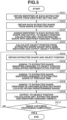
Fig. 5 is a flowchart illustrating an example of tracking analysis processing by a tracking unit. -
Figs. 6A and 6B are diagrams each illustrating an example of a method for assigning the identifiers to the extracted shapes. -
Figs. 7A and 7B are diagrams illustrating reassignment of the identifiers via the GUI. -
Figs. 8A and 8B are diagrams each illustrating an example of how a viewpoint designation unit uses object position information. -
Fig. 9 is a block diagram illustrating an example of a computer hardware configuration. -
Fig. 1 illustrates an example of a configuration of an image processing system that generates a virtual viewpoint image according to a first embodiment of the present invention. For example, the image processing system includes a plurality ofimage capturing units 1, asynchronization unit 2, a three-dimensionalshape estimation unit 3, an accumulation unit 4, aviewpoint designation unit 5, animage generation unit 6, adisplay unit 7, a sound collection unit 8, a soundsignal generation unit 9, asound output unit 10, ashape extraction unit 11, atracking unit 12, an objectposition calculation unit 13, and anidentifier setting unit 14. The image processing system may include one image processing apparatus or a plurality of image processing apparatuses. In the following description, a case will be described where the image processing system includes one image processing apparatus. - Operations of components of an image processing apparatus which generates a virtual viewpoint image and to which the image processing system according to the present embodiment is applied will be schematically described. First, the plurality of
image capturing units 1 captures images in synchronization with each other based on a synchronization signal from thesynchronization unit 2. Theimage capturing units 1 are video cameras that capture images as video data comprising a plurality of frames. Theimage capturing units 1 output the captured images to the three-dimensionalshape estimation unit 3. Theimage capturing units 1 are arranged around an image capturing region including an object in order to enable capturing the images of the object from a plurality of directions. The three-dimensionalshape estimation unit 3 extracts, for example, a silhouette of the object using the input captured images viewed from a plurality of viewpoints, and generates a three-dimensional shape of the object using a volume intersection method or the like. The three-dimensionalshape estimation unit 3 outputs the generated three-dimensional shape of the object and the captured images to the accumulation unit 4. In the present embodiment, the object is a three-dimensional shape generation target, and examples of the object include a person and an article used by a person. - The sound collection unit 8 collects sounds at a plurality of positions in the image capturing region or a sound from each object, and outputs data of the collected sounds to the accumulation unit 4.
- The accumulation unit 4 stores and accumulates the following data group as data (material data) used to generate a virtual viewpoint image. More specifically, the data used to generate a virtual viewpoint image includes the captured images and the three-dimensional shape of the object that are input from the three-dimensional
shape estimation unit 3. The data used to generate a virtual viewpoint image also includes camera parameters, such as the position, orientation and optical characteristics of each of theimage capturing units 1, and the sound data obtained by the sound collection unit 8. In addition, a background model and a background texture image are stored (recorded) in advance in the accumulation unit 4, as data used to generate the background of the virtual viewpoint image. - The
viewpoint designation unit 5 includes a viewpoint operation unit that is a physical user interface, such as a joy stick or a jog dial (not illustrated), and a display unit for displaying the virtual viewpoint image. - The virtual viewpoint of the virtual viewpoint image displayed on the display unit can be changed by the viewpoint operation unit.
- In response to the change of the virtual viewpoint via the viewpoint operation unit, the virtual viewpoint image is generated as appropriate by the image generation unit 6 (described below) and displayed on the display unit. The
viewpoint designation unit 5 may use the display unit 7 (described below) as the display unit, or may include the display unit separately. Theviewpoint designation unit 5 generates virtual viewpoint information based on the input from the viewpoint operation unit, and outputs the generated virtual viewpoint information to theimage generation unit 6. The virtual viewpoint information includes information corresponding to external camera parameters, such as the position and orientation of the virtual viewpoint, information corresponding to internal camera parameters, such as a focal length and an angle of view, and time information designating an image capturing time of the image to be reproduced. - The
image generation unit 6 obtains the material data corresponding to the designated image capturing time from the accumulation unit 4, based on the time information included in the input virtual viewpoint information. Theimage generation unit 6 generates the virtual viewpoint image based on the set virtual viewpoint, using the captured images and the three-dimensional shape of the object included in the obtained material data, and outputs the generated virtual viewpoint image to thedisplay unit 7. - The
display unit 7 displays the image input from theimage generation unit 6. Thedisplay unit 7 is, for example, a display or a head-mounted display (HMD). - The sound
signal generation unit 9 obtains the sound data corresponding to the designated image capturing time from the accumulation unit 4, based on the time information included in the input virtual viewpoint information. The soundsignal generation unit 9 arranges, on a three-dimensional space, the obtained sound data as a virtual sound source. The soundsignal generation unit 9 generates a sound signal based on the distance in position between the virtual sound source and the virtual viewpoint and the direction of the virtual viewpoint, and outputs the generated sound signal to thesound output unit 10. - The
sound output unit 10 includes a speaker, a headphone, or the like, and performs sound output (reproduction) based on the input sound signal. - A method for tracking an object position according to the present embodiment will be described.
- First, the three-dimensional
shape estimation unit 3 generates the three-dimensional shape of each object, and outputs the generated three-dimensional shape to the accumulation unit 4 and also to theshape extraction unit 11. - The
shape extraction unit 11 clips, from the three-dimensional shape of each object illustrated inFig. 2A , a lower part of the three-dimensional shape of each object as illustrated inFig. 2B . In the present embodiment, theshape extraction unit 11 clips a part of the three-dimensional shape of each object corresponding to a predetermined height (e.g., 50 cm) from a bottom surface of a circumscribed cuboid of the three-dimensional shape. For example, as illustrated inFig. 2C , in a case where one object is standing on a floor surface, and the other object is, for example, jumping and is apart from the floor surface, parts illustrated inFig. 2D are clipped from the three-dimensional shapes of the objects. In other words, from the three-dimensional shape of each object, a part corresponding to the predetermined height from the object's feet is clipped. - Next, as illustrated in
Fig. 2E , theshape extraction unit 11 generates a two-dimensional image by performing plane projection of the clipped parts of the three-dimensional shapes seen from directly above the objects. In the present embodiment, theshape extraction unit 11 performs parallel projection of the clipped parts of the three-dimensional shapes on a two-dimensional plane corresponding to the feet (the floor surface). In the present embodiment, the image generated by the plane projection is a binary image including a white portion indicating the clipped parts of the three-dimensional shapes, and a black portion indicating the other area. Theshape extraction unit 11 divides the two-dimensional image into independent regions, and determines circumscribedrectangles 201 to 204 as illustrated inFig. 2E . Theshape extraction unit 11 outputs information about vertices of the circumscribedrectangles 201 to 204, as extracted three-dimensional shapes (or extracted shapes). At this time, theshape extraction unit 11 converts the information about the vertices of the circumscribedrectangles 201 to 204 into the same coordinate system and unit as those of the three-dimensional space of the image capturing region, and outputs the resulting information. Theshape extraction unit 11 determines the independent shapes using a method, such as a continuous component analysis on the two-dimensional image generated by the projection. By using such a method, theshape extraction unit 11 can divide the three-dimensional shapes into independent regions. - The
identifier setting unit 14 assigns an identifier to each of the extracted shapes output from theshape extraction unit 11. More specifically, theidentifier setting unit 14 calculates distances between the extracted shapes, and assigns an identifier to each of the extracted shapes based on the distances therebetween. For example, as illustrated inFig. 3A , theidentifier setting unit 14 assigns the same identifier to the extracted shapes located at a distance (indicated by each solid line arrow) smaller than a predetermined distance, and assigns different identifiers to the extracted shapes located at the predetermined distance or larger (indicated by a broken line arrow). A threshold for the predetermined distance used as a determination criterion is desirably a distance corresponding to the width between the feet of a standing object. In the present embodiment, a description will be given of a case where the threshold for the predetermined distance is set to 50 cm. - The
identifier setting unit 14 displays the assigned identifiers on a display unit of theidentifier setting unit 14 by using a graphical user interface (GUI) as illustrated inFig. 3B . The user operates the image processing system while watching the GUI. More specifically, theidentifier setting unit 14 displays the current assignment state (the initial assignment state) of the identifiers on the GUI in a manner distinguishing the identifiers from each other in at least one of text and color. InFig. 3B , theidentifier setting unit 14 displays the identifiers distinguished from each other in both text and color. The user views the GUI to check whether the initial assignment state of the identifiers is a desired assignment state. In a case where the initial assignment state of the identifiers is not a desired assignment state, the user instructs each object to change the standing position or close the feet, and repeats this operation until the desired assignment state is obtained. Alternatively, the user operates the image processing system via the GUI, and provides a change instruction so as to obtain the desired assignment state. In a case where the desired assignment state is obtained, the user presses, for example, a determination button (an initial identifier determination button) on the GUI illustrated inFig. 3B . In response to this operation, theidentifier setting unit 14 determines the initial identifiers. Theidentifier setting unit 14 then outputs the identifiers assigned to the respective extracted shapes to thetracking unit 12. - The
tracking unit 12 assigns the initial identifiers to the respective extracted shapes when the identifiers are input from theidentifier setting unit 14. Thetracking unit 12 then tracks the extracted shapes with the identifiers assigned thereto. The identifiers to be assigned to the extracted shapes in the tracking are not the identifiers determined by theidentifier setting unit 14, but the identifiers determined based on results of tracking the positions of the extracted shapes by thetracking unit 12. In the tracking (the tracking analysis) of the extracted shapes, thetracking unit 12 tracks the extracted shapes based on positions of the extracted shapes at a time immediately preceding the image capturing time of the extracted shapes, the identifiers of the extracted shapes, and object position information input from the object position calculation unit 13 (described below). Tracking processing by thetracking unit 12 will be specifically described below. Thetracking unit 12 assigns an identifier to each extracted shape at each time based on the tracking analysis results, and outputs each extracted shape to the objectposition calculation unit 13. - The object
position calculation unit 13 calculates a representative position for each extracted shape with the identifier assigned thereto input from thetracking unit 12. For example, as illustrated inFig. 4 , the objectposition calculation unit 13 calculates a position indicating each extracted shape group with the same identifier assigned thereto, likerepresentative positions - Even if an object is standing still, the representative position may fluctuate at each time because the representative position is affected by shape estimation errors or fluctuations of the boundary portion occurring when the shape is clipped by the
shape extraction unit 11. For this reason, in the present embodiment, the objectposition calculation unit 13 performs processing in a temporal direction, such as low-pass filter processing and moving averaging processing, on the center position information at each time, thereby generating the position information with high-frequency components reduced. The objectposition calculation unit 13 then outputs, as the position of each object, the position information about the representative position together with the identifier to thetracking unit 12. The objectposition calculation unit 13 also stores (accumulates), in the accumulation unit 4, information obtained by adding the information about the image capturing time of the three-dimensional shapes, which is a basis of the tracking analysis, to the position information about each representative position, as object position information. - The sound
signal generation unit 9 obtains, from the accumulation unit 4, the sound data and the object position information that correspond to the designated image capturing time, based on the time information included in the virtual viewpoint information. In the present embodiment, since the object position information does not include information in the height direction, the soundsignal generation unit 9 adds the height information corresponding to each object to the object position information. For example, in the present embodiment, the soundsignal generation unit 9 adds the height information corresponding to a mouth or a musical instrument of each object, to the object position information. The soundsignal generation unit 9 then associates, with the object position information, the sound data that is collected by the sound collection unit 8 (e.g., a microphone) and corresponds to the identifier assigned to the object position information including the height information. In this way, the soundsignal generation unit 9 can add the position of the virtual sound source for reproducing the associated sound data to each position indicated by the object position information. - With the above-described system configuration, the image processing system can generate stereoscopic sounds based on the viewpoint position of the virtual viewpoint image and the position of each object in the virtual viewpoint image. The virtual viewpoint image generated by the image processing system enables the user to enjoy a more realistic image and sound experience.
- Next, an example of tracking analysis processing on the position of each extracted shape by the
tracking unit 12 will be described with reference to a flowchart illustrated inFig. 5 . - In step S501, the
tracking unit 12 receives an input from theidentifier setting unit 14 and performs initialization processing. More specifically, thetracking unit 12 obtains the identifier of each extracted shape input from theidentifier setting unit 14. - In step S502, the
tracking unit 12 obtains each extracted shape input from theshape extraction unit 11. - In step S503, the
tracking unit 12 respectively assigns, to the obtained extracted shapes, the identifiers obtained from theidentifier setting unit 14 and outputs, to the objectposition calculation unit 13, the extracted shapes with the identifiers assigned thereto. - In step S504, the object
position calculation unit 13 calculates an object position from each extracted shape group with the same identifier assigned thereto, and outputs the calculated object position to thetracking unit 12. - The processing performed in steps S501 to S504 corresponds to the initialization processing.
- Processing performed in steps S505 to S509 is performed at each time and repeated while the
image capturing units 1 are capturing object images as frames of captured video data. When theimage capturing units 1 end the image capturing processing (YES in step S510), the processing of this flowchart is ended upon completion of the processing in step S509. - In step S505, the
tracking unit 12 obtains the extracted shapes input from theshape extraction unit 11 and the object positions at the immediately preceding time (the previous time) calculated by the objectposition calculation unit 13. The immediately preceding time indicates, for example, the image capturing time of the extracted shapes generated from the frame in the captured video data immediately preceding the frame in the captured video data corresponding to the extracted shapes currently being processed. In the present embodiment, for the sake of comparison, the time corresponding to the extracted shapes currently being processed is also referred to as the current time. In this case, the current time indicates the capturing time of the image in the video data used to generate the extracted shapes currently being processed. - In step S506, in a case where the representative position of each extracted shape at the current time overlaps an object position at the previous time, the
tracking unit 12 assigns, to the extracted shape, the identifier assigned to the object position overlapping the representative position. In this step, in a case where the representative position of one extracted shape overlaps a plurality of object positions, thetracking unit 12 assigns, to the extracted shape, an identifier indicating "undeterminable" at the current time. In the processing of step S506, the identifier indicating "undeterminable" is assigned because a plurality of extracted shapes with different identifiers assigned thereto may overlap each other at the current time, like a state where two objects are close to each other. Processing in step S509 (described below) is performed on the extracted shapes to which the identifiers including the identifier indicating "undeterminable" are assigned. - In step S507, in a case where the position of the extracted shape to with an identifier has not yet been assigned overlaps the position of an extracted shape at the previous time, the
tracking unit 12 assigns the identifier assigned to the extracted shape at the previous time, to the extracted shape at the current time. - In step S508, in a case where another extracted shape to which an identifier has already been assigned at the current time is within a predetermined range from the extracted shape to which an identifier has not yet been assigned, the
tracking unit 12 assigns the identifier assigned to the other extracted shape, to the extracted shape to which an identifier has not yet been assigned. The predetermined range is desirably a range corresponding to the width between the feet of a standing object. For example, the predetermined range is a range with a radius of 50 cm from the center of the extracted shape. At this time, in a case where a plurality of other extracted shapes to which identifiers have already been assigned is within the predetermined range from a certain extracted shape, thetracking unit 12 assigns, to the certain extracted shape, the identifier of the extracted shape closest thereto among the other extracted shapes. Thetracking unit 12 determines an extracted shape to which no identifier has been assigned at the time of completion of the processing up to step S508, as a non-tracking target. In this case, thetracking unit 12 does not output, to the objectposition calculation unit 13, the extracted shape determined as the non-tracking target. - In step S509, the
tracking unit 12 outputs, to the objectposition calculation unit 13, the extracted shapes to which the identifiers are assigned in the processing in steps S506 to S508, and the identifiers assigned thereto. - In step S510, a control unit (not illustrated) determines whether the image capturing processing by the
image capturing units 1 is completed. In a case where the control unit determines that the image capturing processing by theimage capturing units 1 is not completed (NO in step S510), the processing returns to step S505 to repeat the processing in steps S505 to S509. In a case where the control unit determines that the image capturing processing by theimage capturing units 1 is completed (YES in step S510), the processing in the flowchart ends. - Each processing in steps S506 to S508 is performed on each extracted shape. By repeating the processing in steps S506 to S509, the identifiers set by the
identifier setting unit 14 are associated with the extracted shapes at each time. Using the associated identifiers, the objectposition calculation unit 13 can calculate the object positions for the respective objects in a distinguished manner. - In a case where the
tracking unit 12 assigns the identifier indicating "undeterminable" to an extracted shape, some of the initial identifiers may not be assigned at a certain time. In such a case, the objectposition calculation unit 13 does not update the object position information corresponding to the same identifier as the identifier that has not been assigned to an extracted shape. In this way, even in a case where extracted shapes overlap because, for example, a plurality of objects comes closer, a plurality of pieces of object position information does not indicate the same position. In this case, a plurality of respective object positions at the previous time is maintained. Then, in a case where the overlapping plurality of extracted shapes has separated again because the objects have separated from each other, identifiers are assigned to the respective extracted shapes based on the latest object positions. In other words, when the overlap of the plurality of extracted shapes is resolved, the update of the respective pieces of object position information resumes. - Through the above-described processing, even in a case where a plurality of objects is present in an image capturing region, the image processing system can track each of the objects and obtain position information about of each of the objects. Further, through the above-described processing, the image processing system can easily track each of the objects even in a case where overlap and separation occur between generated three-dimensional shape models because, for example, the objects come close and separate. In this way, even in a case where, for example, a plurality of artists changes their positions while singing or comes close to hold their hands, the image processing system can generate a virtual viewpoint image with stereoscopic sounds as if the sounds are output from the respective mouths of the objects. By watching such a virtual viewpoint image, the user can enjoy a more realistic image and sound experience.
- In the first embodiment, a specific example of the image processing system has been described, but embodiments of the present invention are not limited thereto.
- For example, in the first embodiment, the
shape extraction unit 11 is configured to receive the shape estimation result by the three-dimensionalshape estimation unit 3 from the three-dimensionalshape estimation unit 3, but theshape extraction unit 11 is not limited thereto. For example, theshape extraction unit 11 may obtain the shape estimation result by the three-dimensionalshape estimation unit 3 from among the shape estimation results accumulated by the three-dimensionalshape estimation unit 3 in the accumulation unit 4. - In the first embodiment, the predetermined height from the bottom surface of the circumscribed cuboid of each three-dimensional shape, based on which the
shape extraction unit 11 clips a part of the three-dimensional shape, is 50 cm, but the predetermined height may not necessarily be 50 cm. - For example, the predetermined height may be set in a range from 20 cm to 100 cm. Alternatively, the predetermined height may be automatically set to a height between the knees and waist of each object based on the height of the object.
- In the first embodiment, the
shape extraction unit 11 clips a part of each three-dimensional shape corresponding to the predetermined height from the bottom surface of the circumscribed cuboid of the three-dimensional shape, but the clipping method is not limited thereto. Theshape extraction unit 11 may uniformly clip parts of the three-dimensional shapes corresponding to a predetermined height from the floor surface in the image capturing region. In this case, if an object is on a structure, such as a stepstool, in the image capturing region, theshape extraction unit 11 may extract the object shape corresponding to a predetermined height from a top surface of the structure. - In the first embodiment, the
shape extraction unit 11 projects the clipped parts of the three-dimensional shapes onto the two-dimensional plane to divide the clipped parts into independent shapes, but theshape extraction unit 11 is not limited thereto. For example, theshape extraction unit 11 may directly divide the clipped parts of the three-dimensional shapes after determining whether the clipped parts are independent from each other. - In this case, in the subsequent processing, the
tracking unit 12 tracks each object based on the three-dimensional shape of the object. - As an example of the distance in which the
identifier setting unit 14 according to the first embodiment assigns the same identifier to a plurality of extracted shapes, a distance (of 50 cm) corresponding to the width between the feet of a standing object is described to be desirable, but the distance is not necessarily limited thereto. For example, in a case where an object narrows the width between the feet because, for example, there are many objects and the distances therebetween are short, the distance in which the same identifier is assigned to a plurality of extracted shapes may be set to a short distance, such as 30 cm. On the other hand, in a case where an object can widen the width between the feet, such as a case where the image capturing region is wide, the distance in which the same identifier is assigned to a plurality of extracted shapes may be set to a long distance, such as 100 cm. - In the first embodiment, the
identifier setting unit 14 is configured to assign identifiers to the extracted shapes based on the distances between the extracted shapes, but theidentifier setting unit 14 is not necessarily limited thereto. For example, theidentifier setting unit 14 may determine in which of the circumscribed cuboids of the three-dimensional shapes each extracted shape is included, and assign an identifier to the extracted shape. For example, in an example illustrated inFig. 6A , theidentifier setting unit 14 assigns an identifier "A" to extractedshapes cuboid 601, and assigns an identifier "B" to extractedshapes cuboid 602. Alternatively, the user may predetermine an area to which a predetermined identifier is to be assigned by theidentifier setting unit 14. For example, as illustrated inFig. 6B , first, the user inputs information about adetermination area 611 with the identifier "A" assigned thereto, and information about adetermination area 612 with the identifier "B" assigned thereto, to the image processing system via an input unit (not illustrated). Then, theidentifier setting unit 14 assigns the identifier "A" to extractedshapes determination area 611, and the identifier "B" to extractedshapes determination area 612. - In the first embodiment, the
identifier setting unit 14 automatically sets and assigns an identifier to each extracted shape, but the assignment method is not necessarily limited thereto. The user may determine the identifier to be assigned to each extracted shape. For example, a case will now be described where a plurality of objects is present and the user reassigns an identifier to each of the objects after the assignment of an identifier to each of the objects. In this case, for example, the user issues an instruction to shift to an identifier reassignment mode via a GUI illustrated inFig. 7A . The user then designates identifiers to be assigned to the objects by sequentially clickingobject positions 701 to 703 displayed on a screen illustrated inFig. 7A . For example, suppose that an identifier "C" is assigned to theobject position 701, the identifier "A" to theobject position 702, and the identifier "B" to theobject position 703. In a case where the user desires to assign the identifiers "A", "B", and "C" to the object positions 701, 702, and 703, respectively, in this order, the user clicks the object positions 701 to 703 in this order. Theidentifier setting unit 14 receives the order of the clickedobject positions 701 to 703 and reassigns the identifiers "A", "B", and "C" based on the received order as illustratedFig. 7B . Theidentifier setting unit 14 then outputs the extracted shapes and the identifiers reassigned thereto, to thetracking unit 12. - The configuration according to the first embodiment has been described in which the object position information about each object subjected to the tracking analysis is used as the sound source reproduction position, but the object position information is not necessarily limited thereto. For example, the
viewpoint designation unit 5 may obtain and use the object position information accumulated in the accumulation unit 4. In this case, theviewpoint designation unit 5 may generate a virtual viewpoint capable of constantly revolving around an object even though the object moves, by setting, for example, a rotation center position of the virtual viewpoint to anobject position 800 as illustrated inFig. 8A . Alternatively, theviewpoint designation unit 5 may set, for example, a line-of-sight direction of the virtual viewpoint to theobject position 800 as illustrated inFig. 8B . In this case, the image processing system can generate a virtual viewpoint image based on the virtual viewpoint that is placed at a half-fixed position and automatically revolves in the horizontal direction accompanying with the movement of the object. - The processing units illustrated in
Fig. 1 have been described to be hardware components in the above-described embodiments. In one embodiment, the processing performed by the processing units illustrated inFig. 1 may be performed using a computer program. -
Fig. 9 is a block diagram illustrating an example of a hardware configuration of a computer applicable to the image processing system according to the above-described embodiments. - A central processing unit (CPU) 901 controls the entire computer by using a computer program and data stored in a random access memory (RAM) 902 or a read-only memory (ROM) 903, and executes the above-described processing performed by the image processing system according to the above-described embodiments. In other words, the
CPU 901 functions as the processing units illustrated inFig. 1 . - The
RAM 902 includes an area for temporarily storing a computer program and data loaded from anexternal storage device 906, data obtained from an external apparatus via an interface (I/F) 907, and the like. TheRAM 902 also includes a work area to be used when theCPU 901 executes various kinds of processing. For example, theRAM 902 can assign an area as a frame memory, or can provide various other areas as appropriate. - The
ROM 903 stores setting data of the computer, a boot program, and the like. Anoperation unit 904 includes a keyboard and a mouse, and can input various kinds of instructions to theCPU 901 based on a user's operation. Anoutput unit 905 displays a processing result of theCPU 901. Theoutput unit 905 includes, for example, a liquid crystal display. For example, theoperation unit 904 serves as theviewpoint designation unit 5, and theoutput unit 905 serves as thedisplay unit 7. - The
external storage device 906 is a large-capacity information storage device typified by a hard disk drive device. Theexternal storage device 906 stores an operating system (OS) and a computer program for causing theCPU 901 to implement the functions of the processing units illustrated inFig. 1 . Theexternal storage device 906 may further store pieces of image data serving as processing targets. - The computer program and data stored in the
external storage device 906 are loaded into theRAM 902 as appropriate under the control of theCPU 901 and processed by theCPU 901. Networks, such as a local area network (LAN) and the Internet, and other devices, such as a projection device and a display device, can be connected to the I/F 907, and the computer can obtain and output various kinds of information via the I/F 907. In the first embodiment, theimage capturing units 1 are connected to the I/F 907, the images captured by theimage capturing units 1 are input via the I/F 907, and theimage capturing units 1 are controlled via the I/F 907. Abus 908 connects the above-described components. - The
CPU 901 centrally controls operations to be performed with the above-described configuration, in a similar manner to the operations described in the above-described embodiments. - In another configuration, the embodiments of the present invention can be implemented by supplying, to a system, a storage medium storing a code of a computer program for implementing the above-described functions, and causing the system to read and execute the code of the computer program. In this case, the code of the computer program read from the storage medium implements the functions according to the above-described embodiments, and the storage medium storing the code of the computer program is included in the embodiments of the present invention. Further, a configuration where the OS running on the computer executes part or all of the actual processing based on the instructions of the program code to implement the above-described functions is included in the embodiments of the present invention.
- The embodiments may also be implemented with the following configuration. More specifically, a computer program code read from a storage medium is written into a memory provided in a function expansion card inserted in a computer, or a memory provided in a function expansion unit connected to the computer. Then, the above-described functions are implemented by a CPU, in the function expansion card or the function expansion unit, executing part or all of the actual processing based on the instructions of the computer program code. This configuration is also included in the embodiments of the present invention.
- In a case where the embodiments of the present invention are applied to the above-described storage medium, the computer program code corresponding to the above-described processing is stored in the storage medium.
- Embodiment(s) of the present invention can also be realized by a computer of a system or apparatus that reads out and executes computer executable instructions (e.g., one or more programs) recorded on a storage medium (which may also be referred to more fully as a 'non-transitory computer-readable storage medium') to perform the functions of one or more of the above-described embodiment(s) and/or that includes one or more circuits (e.g., application specific integrated circuit (ASIC)) for performing the functions of one or more of the above-described embodiment(s), and by a method performed by the computer of the system or apparatus by, for example, reading out and executing the computer executable instructions from the storage medium to perform the functions of one or more of the above-described embodiment(s) and/or controlling the one or more circuits to perform the functions of one or more of the above-described embodiment(s). The computer may comprise one or more processors (e.g., central processing unit (CPU), micro processing unit (MPU)) and may include a network of separate computers or separate processors to read out and execute the computer executable instructions. The computer executable instructions may be provided to the computer, for example, from a network or the storage medium. The storage medium may include, for example, one or more of a hard disk, a random-access memory (RAM), a read only memory (ROM), a storage of distributed computing systems, an optical disk (such as a compact disc (CD), digital versatile disc (DVD), or Blu-ray Disc (BD)™), a flash memory device, a memory card, and the like.
- While the present invention has been described with reference to embodiments, it is to be understood that the invention is not limited to the disclosed embodiments but is defined by the scope of the following claims.
Claims (19)
- An image processing system comprising:shape estimation means (3) configured to generate three-dimensional shape data of at least one object using images of the at least one object captured from a plurality of directions by a plurality of image capturing means (1);shape extraction means (11) configured to extract a plurality of parts of the generated three-dimensional shape data;identifier setting means (14) configured to assign identifiers to the extracted plurality of parts based on positions of the extracted plurality of parts; andtracking means (12) configured to track the extracted plurality of parts based on the identifiers and the positions of the extracted plurality of parts.
- The image processing system according to claim 1, wherein the shape extraction means (11) is configured to extract the plurality of parts by clipping a part of the three-dimensional shape data.
- The image processing system according to claim 1 or 2, wherein the shape extraction means (11) is configured to extract the plurality of parts corresponding to feet in the three-dimensional shape data.
- The image processing system according to any one of the preceding claims, wherein the shape extraction means (11) is configured to project the plurality of parts onto a two-dimensional plane corresponding to a floor surface to generate a two-dimensional image, clip the plurality of parts as independent regions on the two-dimensional image, and output respective circumscribed rectangles of the independent regions on the two-dimensional image.
- The image processing system according to any one of the preceding claims, wherein the shape extraction means (11) is configured to extract a shape corresponding to a predetermined height from a bottom surface of a circumscribed cuboid of the three-dimensional shape data.
- The image processing system according to any one of claims 1 to 5, wherein the shape extraction means (11) is configured to extract a shape corresponding to a predetermined height from a floor surface of an image capturing region in the three-dimensional shape data.
- The image processing system according to any one of claims 1 to 5, wherein, in a case where the at least one object is located on a structure placed in an image capturing region, the shape extraction means (11) is configured to extract a shape corresponding to a predetermined height from a top surface of the structure in the three-dimensional shape data.
- The image processing system according to any one of the preceding claims, further comprising object position calculation means (13) configured to calculate a representative position of parts, among the extracted plurality of parts, to which the same identifier is assigned based on a result of the tracking by the tracking means (12), and output the representative position as an object position.
- The image processing system according to any one of the preceding claims, wherein the identifier setting means (14) is configured to assign an identifier to each of the plurality of parts based on a distance between the plurality of parts of the three-dimensional shape data.
- The image processing system according to any one of the preceding claims, wherein the identifier setting means (14) is configured to determine in which circumscribed cuboid in the three-dimensional shape data each of the extracted plurality of parts is included, and assign the same identifier to parts included in the same circumscribed cuboid among the extracted plurality of parts.
- The image processing system according to any one of the preceding claims, wherein the identifier setting means (14) is configured to set a region in which a predetermined identifier is to be assigned, and assign the predetermined identifier to parts included in the region among the extracted plurality of parts.
- The image processing system according to any one of the preceding claims, wherein, the identifier setting means (14) is configured to, based on a user's instruction, reassign the identifiers to the extracted plurality of parts to which the identifiers have been assigned.
- The image processing system according to claim 8, wherein the tracking means (12) is configured to, based on the identifiers and the object position at a time immediately preceding an image capturing time of the extracted plurality of parts, assign the identifiers to the extracted plurality of parts.
- The image processing system according to claim 13, wherein the tracking means (12) is configured to, based on the identifiers and the positions of the extracted plurality of parts at the immediately preceding time, assign the identifiers to the extracted plurality of parts.
- The image processing system according to claim 14, wherein the tracking means (12) is configured to:assign, among the extracted plurality of parts, to a part at a position overlapping the object position at the immediately preceding time, the identifier corresponding to the object position, and then determine whether a position of a part to which no identifier has yet been assigned overlaps one of the positions of the extracted plurality of parts at the immediately preceding time,in a case where the position of the part overlaps one of the positions of the extracted plurality of parts at the immediately preceding time, assign, to the part, the identifier of the corresponding part at the immediately preceding time, andin a case where the position of the part does not overlap any of the positions of the extracted plurality of parts at the immediately preceding time, assign, to the part, the identifier of a part closest to the part in a predetermined range among the extracted plurality of parts.
- The image processing system according to claim 15, wherein the tracking means (12) is configured to, in a case where, among the extracted plurality of parts, there is a part at a position overlapping a plurality of the object positions at the immediately preceding time, assign no identifier to the part, and not update position information about all the plurality of object positions.
- The image processing system according to any one of the preceding claims, further comprising:viewpoint designation means (5) configured to obtain a virtual viewpoint, andimage generation means (6) configured to generate a virtual viewpoint image based on the virtual viewpoint, the three-dimensional shape data, and a result of the tracking by the tracking means (12).
- A method for controlling an image processing system, the method comprising:generating three-dimensional shape data of at least one object using images of the at least one object captured from a plurality of directions by a plurality of image capturing means (1);extracting a plurality of parts of the generated three-dimensional shape data;assigning identifiers to the extracted plurality of parts based on positions of the extracted plurality of parts; andtracking the extracted plurality of parts based on the identifiers and the positions of the extracted plurality of parts.
- A program for causing a computer to perform the method according to claim 18.
Applications Claiming Priority (1)
| Application Number | Priority Date | Filing Date | Title |
|---|---|---|---|
| JP2022161719A JP7559024B2 (en) | 2022-10-06 | 2022-10-06 | Image processing device, control method, and program |
Publications (2)
| Publication Number | Publication Date |
|---|---|
| EP4350626A1 true EP4350626A1 (en) | 2024-04-10 |
| EP4350626B1 EP4350626B1 (en) | 2025-08-20 |
Family
ID=88241424
Family Applications (1)
| Application Number | Title | Priority Date | Filing Date |
|---|---|---|---|
| EP23201422.5A Active EP4350626B1 (en) | 2022-10-06 | 2023-10-03 | Image processing system, method for controlling the same, and program |
Country Status (4)
| Country | Link |
|---|---|
| US (1) | US20240119668A1 (en) |
| EP (1) | EP4350626B1 (en) |
| JP (2) | JP7559024B2 (en) |
| CN (1) | CN117857765A (en) |
Families Citing this family (2)
| Publication number | Priority date | Publication date | Assignee | Title |
|---|---|---|---|---|
| JP7462017B2 (en) * | 2022-12-01 | 2024-04-04 | 任天堂株式会社 | Audio processing program, information processing system, information processing device, and audio processing method |
| JP2026032420A (en) | 2024-08-13 | 2026-02-26 | キヤノン株式会社 | Image processing device and program |
Citations (2)
| Publication number | Priority date | Publication date | Assignee | Title |
|---|---|---|---|---|
| JP2017211828A (en) | 2016-05-25 | 2017-11-30 | キヤノン株式会社 | Image processing system, image processing apparatus, control method, and program |
| WO2022021217A1 (en) * | 2020-07-30 | 2022-02-03 | Intel Corporation | Multi-camera person association via pair-wise matching in continuous frames for immersive video |
Family Cites Families (13)
| Publication number | Priority date | Publication date | Assignee | Title |
|---|---|---|---|---|
| JP4821355B2 (en) | 2006-02-14 | 2011-11-24 | パナソニック株式会社 | Person tracking device, person tracking method, and person tracking program |
| US8116564B2 (en) * | 2006-11-22 | 2012-02-14 | Regents Of The University Of Minnesota | Crowd counting and monitoring |
| JP2011186519A (en) * | 2010-03-04 | 2011-09-22 | Sony Corp | Information processing device, information processing method, and program |
| JP6406251B2 (en) * | 2013-07-17 | 2018-10-17 | 日本電気株式会社 | Object tracking device, object tracking method, and object tracking program |
| JP2015087903A (en) * | 2013-10-30 | 2015-05-07 | ソニー株式会社 | Apparatus and method for information processing |
| JP6324036B2 (en) | 2013-11-25 | 2018-05-16 | キヤノン株式会社 | Information processing apparatus, information processing method, and program |
| JP6009502B2 (en) | 2014-07-29 | 2016-10-19 | 株式会社ソニー・インタラクティブエンタテインメント | Information processing apparatus and information processing method |
| JP6516646B2 (en) | 2015-09-30 | 2019-05-22 | Kddi株式会社 | Identification apparatus for identifying individual objects from images taken by a plurality of cameras, identification method and program |
| US11430168B2 (en) * | 2019-08-16 | 2022-08-30 | Samsung Electronics Co., Ltd. | Method and apparatus for rigging 3D scanned human models |
| JP7520539B2 (en) | 2020-03-19 | 2024-07-23 | キヤノン株式会社 | Image processing device, image processing method, and program |
| US20230222821A1 (en) * | 2020-05-06 | 2023-07-13 | Eli Lilly And Company | Methods and apparatus for visual-aware hierarchy-based object recognition |
| JP7459949B2 (en) * | 2020-08-27 | 2024-04-02 | 日本電気株式会社 | Learning devices, learning methods, tracking devices and programs |
| JP2024052107A (en) * | 2022-09-30 | 2024-04-11 | ヤマハ発動機株式会社 | Driving control system, driving control method, and computer program |
-
2022
- 2022-10-06 JP JP2022161719A patent/JP7559024B2/en active Active
-
2023
- 2023-10-03 EP EP23201422.5A patent/EP4350626B1/en active Active
- 2023-10-05 US US18/481,938 patent/US20240119668A1/en active Pending
- 2023-10-07 CN CN202311285051.9A patent/CN117857765A/en active Pending
-
2024
- 2024-09-17 JP JP2024159721A patent/JP2024175041A/en active Pending
Patent Citations (2)
| Publication number | Priority date | Publication date | Assignee | Title |
|---|---|---|---|---|
| JP2017211828A (en) | 2016-05-25 | 2017-11-30 | キヤノン株式会社 | Image processing system, image processing apparatus, control method, and program |
| WO2022021217A1 (en) * | 2020-07-30 | 2022-02-03 | Intel Corporation | Multi-camera person association via pair-wise matching in continuous frames for immersive video |
Non-Patent Citations (5)
| Title |
|---|
| KHAN SAAD M ET AL: "A Multiview Approach to Tracking People in Crowded Scenes Using a Planar Homography Constraint", 31 May 2006, TOPICS IN CRYPTOLOGY - CT-RSA 2020 : THE CRYPTOGRAPHERS' TRACK AT THE RSA CONFERENCE 2020, SAN FRANCISCO, CA, USA, FEBRUARY 24-28, 2020, PAGE(S) 133 - 146, XP047529953 * |
| KONG-MAN (GERMAN) CHEUNG ET AL: "Shape-From-Silhouette Across Time Part II: Applications to Human Modeling and Markerless Motion Tracking", INTERNATIONAL JOURNAL OF COMPUTER VISION, KLUWER ACADEMIC PUBLISHERS, BO, vol. 63, no. 3, 1 July 2005 (2005-07-01), pages 225 - 245, XP019216472, ISSN: 1573-1405, DOI: 10.1007/S11263-005-6879-4 * |
| MATTHIAS STRAKA: "Human Pose and Shape Estimation from Multi-View Images for Virtual Dressing Rooms", DISSERTATION, 1 January 2014 (2014-01-01), Graz, Austria, XP055382018, Retrieved from the Internet <URL:https://diglib.tugraz.at/download.php?id=576a7d2822561&location=browse> [retrieved on 20170615] * |
| ROBERTO VEZZANI ET AL: "People reidentification in surveillance and forensics", ARXIV, ACM, NEW YORK, NY, US, US, vol. 46, no. 2, 27 December 2013 (2013-12-27), pages 1 - 37, XP058036552, ISSN: 0360-0300, DOI: 10.1145/2543581.2543596 * |
| XIE FANGLU ET AL: "Mixture particle filter with block jump biomechanics constraint for volleyball players lower body parts tracking", 2017 FIFTEENTH IAPR INTERNATIONAL CONFERENCE ON MACHINE VISION APPLICATIONS (MVA), MVA ORGANIZATION, 8 May 2017 (2017-05-08), pages 302 - 305, XP033126587, DOI: 10.23919/MVA.2017.7986861 * |
Also Published As
| Publication number | Publication date |
|---|---|
| US20240119668A1 (en) | 2024-04-11 |
| JP2024175041A (en) | 2024-12-17 |
| JP7559024B2 (en) | 2024-10-01 |
| CN117857765A (en) | 2024-04-09 |
| EP4350626B1 (en) | 2025-08-20 |
| JP2024055093A (en) | 2024-04-18 |
Similar Documents
| Publication | Publication Date | Title |
|---|---|---|
| US11012679B2 (en) | Generating apparatus, generating method, and storage medium | |
| US10762653B2 (en) | Generation apparatus of virtual viewpoint image, generation method, and storage medium | |
| KR102215166B1 (en) | Providing apparatus, providing method and computer program | |
| EP3285484B1 (en) | Image processing apparatus, image generation method, and program | |
| JP7127659B2 (en) | Information processing device, virtual/reality synthesis system, method for generating learned model, method for executing information processing device, program | |
| EP4350626B1 (en) | Image processing system, method for controlling the same, and program | |
| CN109906600B (en) | Simulate depth of field | |
| US11503272B2 (en) | Information processing apparatus, information processing method and storage medium | |
| JP2011234226A (en) | Video editing apparatus, and video editing method and program | |
| KR20140082610A (en) | Method and apaaratus for augmented exhibition contents in portable terminal | |
| CN113411684B (en) | Video playing method and device, storage medium and electronic equipment | |
| US20230353717A1 (en) | Image processing system, image processing method, and storage medium | |
| US20240428455A1 (en) | Image processing apparatus, image processing method, and storage medium | |
| US11895288B2 (en) | Information processing device, proposal device, information processing method, and proposal method | |
| KR102255181B1 (en) | Metohd and appartus for generating augumented reality video using multiple cameras | |
| JP2009246917A (en) | Video display device, and video processing apparatus | |
| JP7672283B2 (en) | Video processing device, control method and program thereof | |
| KR102575771B1 (en) | Method and system for generating 3d interactive video | |
| CN113485547B (en) | An interactive method and device for holographic sandbox | |
| JP2023167486A (en) | Image processing device, image processing method and program | |
| JP2019103126A (en) | Camera system, camera control device, camera control method, and program | |
| KR20200143293A (en) | Metohd and appartus for generating augumented reality video for real-time multi-way ar broadcasting | |
| KR102487976B1 (en) | Electronic device and operating method for the same | |
| JP7354185B2 (en) | Display control device, display control method, and display control program | |
| JP7354186B2 (en) | Display control device, display control method, and display control program |
Legal Events
| Date | Code | Title | Description |
|---|---|---|---|
| PUAI | Public reference made under article 153(3) epc to a published international application that has entered the european phase |
Free format text: ORIGINAL CODE: 0009012 |
|
| STAA | Information on the status of an ep patent application or granted ep patent |
Free format text: STATUS: THE APPLICATION HAS BEEN PUBLISHED |
|
| AK | Designated contracting states |
Kind code of ref document: A1 Designated state(s): AL AT BE BG CH CY CZ DE DK EE ES FI FR GB GR HR HU IE IS IT LI LT LU LV MC ME MK MT NL NO PL PT RO RS SE SI SK SM TR |
|
| STAA | Information on the status of an ep patent application or granted ep patent |
Free format text: STATUS: REQUEST FOR EXAMINATION WAS MADE |
|
| 17P | Request for examination filed |
Effective date: 20241010 |
|
| RBV | Designated contracting states (corrected) |
Designated state(s): AL AT BE BG CH CY CZ DE DK EE ES FI FR GB GR HR HU IE IS IT LI LT LU LV MC ME MK MT NL NO PL PT RO RS SE SI SK SM TR |
|
| GRAP | Despatch of communication of intention to grant a patent |
Free format text: ORIGINAL CODE: EPIDOSNIGR1 |
|
| STAA | Information on the status of an ep patent application or granted ep patent |
Free format text: STATUS: GRANT OF PATENT IS INTENDED |
|
| INTG | Intention to grant announced |
Effective date: 20250319 |
|
| GRAS | Grant fee paid |
Free format text: ORIGINAL CODE: EPIDOSNIGR3 |
|
| GRAA | (expected) grant |
Free format text: ORIGINAL CODE: 0009210 |
|
| STAA | Information on the status of an ep patent application or granted ep patent |
Free format text: STATUS: THE PATENT HAS BEEN GRANTED |
|
| AK | Designated contracting states |
Kind code of ref document: B1 Designated state(s): AL AT BE BG CH CY CZ DE DK EE ES FI FR GB GR HR HU IE IS IT LI LT LU LV MC ME MK MT NL NO PL PT RO RS SE SI SK SM TR |
|
| REG | Reference to a national code |
Ref country code: GB Ref legal event code: FG4D |
|
| REG | Reference to a national code |
Ref country code: CH Ref legal event code: EP |
|
| REG | Reference to a national code |
Ref country code: IE Ref legal event code: FG4D |
|
| REG | Reference to a national code |
Ref country code: DE Ref legal event code: R096 Ref document number: 602023005858 Country of ref document: DE |
|
| REG | Reference to a national code |
Ref country code: NL Ref legal event code: MP Effective date: 20250820 |
|
| PG25 | Lapsed in a contracting state [announced via postgrant information from national office to epo] |
Ref country code: IS Free format text: LAPSE BECAUSE OF FAILURE TO SUBMIT A TRANSLATION OF THE DESCRIPTION OR TO PAY THE FEE WITHIN THE PRESCRIBED TIME-LIMIT Effective date: 20251220 |
|
| PG25 | Lapsed in a contracting state [announced via postgrant information from national office to epo] |
Ref country code: NO Free format text: LAPSE BECAUSE OF FAILURE TO SUBMIT A TRANSLATION OF THE DESCRIPTION OR TO PAY THE FEE WITHIN THE PRESCRIBED TIME-LIMIT Effective date: 20251120 |
|
| REG | Reference to a national code |
Ref country code: LT Ref legal event code: MG9D |
|
| PG25 | Lapsed in a contracting state [announced via postgrant information from national office to epo] |
Ref country code: PT Free format text: LAPSE BECAUSE OF FAILURE TO SUBMIT A TRANSLATION OF THE DESCRIPTION OR TO PAY THE FEE WITHIN THE PRESCRIBED TIME-LIMIT Effective date: 20251222 |
|
| PG25 | Lapsed in a contracting state [announced via postgrant information from national office to epo] |
Ref country code: FI Free format text: LAPSE BECAUSE OF FAILURE TO SUBMIT A TRANSLATION OF THE DESCRIPTION OR TO PAY THE FEE WITHIN THE PRESCRIBED TIME-LIMIT Effective date: 20250820 |
|
| PG25 | Lapsed in a contracting state [announced via postgrant information from national office to epo] |
Ref country code: HR Free format text: LAPSE BECAUSE OF FAILURE TO SUBMIT A TRANSLATION OF THE DESCRIPTION OR TO PAY THE FEE WITHIN THE PRESCRIBED TIME-LIMIT Effective date: 20250820 Ref country code: NL Free format text: LAPSE BECAUSE OF FAILURE TO SUBMIT A TRANSLATION OF THE DESCRIPTION OR TO PAY THE FEE WITHIN THE PRESCRIBED TIME-LIMIT Effective date: 20250820 |
|
| PG25 | Lapsed in a contracting state [announced via postgrant information from national office to epo] |
Ref country code: GR Free format text: LAPSE BECAUSE OF FAILURE TO SUBMIT A TRANSLATION OF THE DESCRIPTION OR TO PAY THE FEE WITHIN THE PRESCRIBED TIME-LIMIT Effective date: 20251121 |
|
| PG25 | Lapsed in a contracting state [announced via postgrant information from national office to epo] |
Ref country code: SE Free format text: LAPSE BECAUSE OF FAILURE TO SUBMIT A TRANSLATION OF THE DESCRIPTION OR TO PAY THE FEE WITHIN THE PRESCRIBED TIME-LIMIT Effective date: 20250820 |
|
| PG25 | Lapsed in a contracting state [announced via postgrant information from national office to epo] |
Ref country code: LV Free format text: LAPSE BECAUSE OF FAILURE TO SUBMIT A TRANSLATION OF THE DESCRIPTION OR TO PAY THE FEE WITHIN THE PRESCRIBED TIME-LIMIT Effective date: 20250820 |
|
| PG25 | Lapsed in a contracting state [announced via postgrant information from national office to epo] |
Ref country code: PL Free format text: LAPSE BECAUSE OF FAILURE TO SUBMIT A TRANSLATION OF THE DESCRIPTION OR TO PAY THE FEE WITHIN THE PRESCRIBED TIME-LIMIT Effective date: 20250820 Ref country code: BG Free format text: LAPSE BECAUSE OF FAILURE TO SUBMIT A TRANSLATION OF THE DESCRIPTION OR TO PAY THE FEE WITHIN THE PRESCRIBED TIME-LIMIT Effective date: 20250820 |
|
| PG25 | Lapsed in a contracting state [announced via postgrant information from national office to epo] |
Ref country code: RS Free format text: LAPSE BECAUSE OF FAILURE TO SUBMIT A TRANSLATION OF THE DESCRIPTION OR TO PAY THE FEE WITHIN THE PRESCRIBED TIME-LIMIT Effective date: 20251120 |
|
| PG25 | Lapsed in a contracting state [announced via postgrant information from national office to epo] |
Ref country code: ES Free format text: LAPSE BECAUSE OF FAILURE TO SUBMIT A TRANSLATION OF THE DESCRIPTION OR TO PAY THE FEE WITHIN THE PRESCRIBED TIME-LIMIT Effective date: 20250820 |
|
| REG | Reference to a national code |
Ref country code: AT Ref legal event code: MK05 Ref document number: 1828150 Country of ref document: AT Kind code of ref document: T Effective date: 20250820 |
|
| PG25 | Lapsed in a contracting state [announced via postgrant information from national office to epo] |
Ref country code: RO Free format text: LAPSE BECAUSE OF FAILURE TO SUBMIT A TRANSLATION OF THE DESCRIPTION OR TO PAY THE FEE WITHIN THE PRESCRIBED TIME-LIMIT Effective date: 20250820 |
|
| PG25 | Lapsed in a contracting state [announced via postgrant information from national office to epo] |
Ref country code: SM Free format text: LAPSE BECAUSE OF FAILURE TO SUBMIT A TRANSLATION OF THE DESCRIPTION OR TO PAY THE FEE WITHIN THE PRESCRIBED TIME-LIMIT Effective date: 20250820 |
|
| PG25 | Lapsed in a contracting state [announced via postgrant information from national office to epo] |
Ref country code: DK Free format text: LAPSE BECAUSE OF FAILURE TO SUBMIT A TRANSLATION OF THE DESCRIPTION OR TO PAY THE FEE WITHIN THE PRESCRIBED TIME-LIMIT Effective date: 20250820 |
|
| PG25 | Lapsed in a contracting state [announced via postgrant information from national office to epo] |
Ref country code: AT Free format text: LAPSE BECAUSE OF FAILURE TO SUBMIT A TRANSLATION OF THE DESCRIPTION OR TO PAY THE FEE WITHIN THE PRESCRIBED TIME-LIMIT Effective date: 20250820 |
|
| PG25 | Lapsed in a contracting state [announced via postgrant information from national office to epo] |
Ref country code: IT Free format text: LAPSE BECAUSE OF FAILURE TO SUBMIT A TRANSLATION OF THE DESCRIPTION OR TO PAY THE FEE WITHIN THE PRESCRIBED TIME-LIMIT Effective date: 20250820 |
|
| PG25 | Lapsed in a contracting state [announced via postgrant information from national office to epo] |
Ref country code: CZ Free format text: LAPSE BECAUSE OF FAILURE TO SUBMIT A TRANSLATION OF THE DESCRIPTION OR TO PAY THE FEE WITHIN THE PRESCRIBED TIME-LIMIT Effective date: 20250820 |
|
| PG25 | Lapsed in a contracting state [announced via postgrant information from national office to epo] |
Ref country code: SK Free format text: LAPSE BECAUSE OF FAILURE TO SUBMIT A TRANSLATION OF THE DESCRIPTION OR TO PAY THE FEE WITHIN THE PRESCRIBED TIME-LIMIT Effective date: 20250820 Ref country code: EE Free format text: LAPSE BECAUSE OF FAILURE TO SUBMIT A TRANSLATION OF THE DESCRIPTION OR TO PAY THE FEE WITHIN THE PRESCRIBED TIME-LIMIT Effective date: 20250820 |