EP3285484B1 - Image processing apparatus, image generation method, and program - Google Patents
Image processing apparatus, image generation method, and program Download PDFInfo
- Publication number
- EP3285484B1 EP3285484B1 EP17185816.0A EP17185816A EP3285484B1 EP 3285484 B1 EP3285484 B1 EP 3285484B1 EP 17185816 A EP17185816 A EP 17185816A EP 3285484 B1 EP3285484 B1 EP 3285484B1
- Authority
- EP
- European Patent Office
- Prior art keywords
- camera
- image
- viewpoint
- captured
- virtual viewpoint
- Prior art date
- Legal status (The legal status is an assumption and is not a legal conclusion. Google has not performed a legal analysis and makes no representation as to the accuracy of the status listed.)
- Active
Links
Images

Classifications
-
- H—ELECTRICITY
- H04—ELECTRIC COMMUNICATION TECHNIQUE
- H04N—PICTORIAL COMMUNICATION, e.g. TELEVISION
- H04N13/00—Stereoscopic video systems; Multi-view video systems; Details thereof
- H04N13/20—Image signal generators
- H04N13/204—Image signal generators using stereoscopic image cameras
- H04N13/243—Image signal generators using stereoscopic image cameras using three or more two-dimensional [2D] image sensors
-
- H—ELECTRICITY
- H04—ELECTRIC COMMUNICATION TECHNIQUE
- H04N—PICTORIAL COMMUNICATION, e.g. TELEVISION
- H04N13/00—Stereoscopic video systems; Multi-view video systems; Details thereof
- H04N13/10—Processing, recording or transmission of stereoscopic or multi-view image signals
- H04N13/106—Processing image signals
- H04N13/111—Transformation of image signals corresponding to virtual viewpoints, e.g. spatial image interpolation
- H04N13/117—Transformation of image signals corresponding to virtual viewpoints, e.g. spatial image interpolation the virtual viewpoint locations being selected by the viewers or determined by viewer tracking
-
- G—PHYSICS
- G06—COMPUTING OR CALCULATING; COUNTING
- G06T—IMAGE DATA PROCESSING OR GENERATION, IN GENERAL
- G06T15/00—Three-dimensional [3D] image rendering
-
- H—ELECTRICITY
- H04—ELECTRIC COMMUNICATION TECHNIQUE
- H04N—PICTORIAL COMMUNICATION, e.g. TELEVISION
- H04N13/00—Stereoscopic video systems; Multi-view video systems; Details thereof
- H04N13/10—Processing, recording or transmission of stereoscopic or multi-view image signals
- H04N13/106—Processing image signals
- H04N13/111—Transformation of image signals corresponding to virtual viewpoints, e.g. spatial image interpolation
-
- H—ELECTRICITY
- H04—ELECTRIC COMMUNICATION TECHNIQUE
- H04N—PICTORIAL COMMUNICATION, e.g. TELEVISION
- H04N23/00—Cameras or camera modules comprising electronic image sensors; Control thereof
- H04N23/90—Arrangement of cameras or camera modules, e.g. multiple cameras in TV studios or sports stadiums
Definitions
- the present invention relates to a technique for generating a virtual viewpoint image from images captured from a plurality of viewpoints.
- generation and viewing of virtual viewpoint content based on multiview images can be realized by compiling images that a plurality of cameras captured in an image processing unit of a server or the like, applying processing such as rendering in the image processing unit, and ultimately transmitting images to a user terminal.
- Japanese Patent Laid-Open No. 2011-170487 A technique for generating virtual viewpoint video is described in Japanese Patent Laid-Open No. 2011-170487 .
- Japanese Patent Laid-Open No. 2011-170487 is described a technique in which an object in video of a plurality of cameras is extracted, three-dimensional coordinates are calculated, and a virtual viewpoint video is generated by re-projection to a plane.
- the re-projection position is erroneous in a case when a state in which multiple objects such as people are overlapped and farther objects are partially hidden by closer objects, so-called occlusion, occurs.
- the processing for separating the plurality of objects requires a method that uses object tracking processing, for example, image recognition, or processing such as machine learning, but the load of such processing tends to be large. Also, there are cases in which an error such as an erroneous separation occurs, and it is difficult to improve performance.
- COOKE E ET AL "Scalable Virtual Viewpoint Image Synthesis for Multiple Camera Environments", INFORMATION VISUALISATION, 2005. PROCEEDINGS. NINTH INTERNATIONAL CONFERENCE ON LONDON ENGLAND 06-08 JULY 2005, PISCATAWAY, NJ, USA, IEEE, 6 July 2005 (2005-07-06), pages 393-397, XP010836360, ISBN: 978-0-7695-2397-2 , which discloses a view synthesis algorithm that provides a scalable and flexible approach to virtual viewpoint synthesis in multiple camera environments.
- a multi-view synthesis (MVS) process consists of four different phases that are described in detail: surface identification, surface selection, surface boundary blending and surface reconstruction.
- MVS view synthesis identifies and selects only the best quality surface areas from the set of available reference images, thereby reducing perceptual errors in virtual view reconstruction.
- the approach is camera setup independent and scalable as virtual views can be created given 1 to N of the available video inputs.
- MVS provides interactive AV applications with a means to handle scenarios where camera inputs increase or decrease over time.
- the present invention in its first aspect provides an image processing apparatus as specified in claims 1 to 8.
- the present invention in its second aspect provides an image generation method as specified in claim 9.
- the present invention in its third aspect provides a program as specified in claim 10.
- the present invention in its fourth aspect provides a computer-readable storage medium as specified in claim 11.
- Virtual viewpoint content in the present embodiment is content that includes a virtual viewpoint image generated by simulating an image obtained when a subject is captured from a virtual viewpoint.
- a viewpoint that is virtual may be designated by a user (operator), and it may be automatically designated based on a result of image analysis or the like. Configuration may also be taken such that virtual viewpoint sound generated by simulating the sound that would be heard from the virtual viewpoint is included in the virtual viewpoint content of the present embodiment.
- a method of generating a virtual viewpoint image is described in detail below.
- the image processing apparatus of the present embodiment specifies a camera viewpoint for which occlusion of an object is not occurring out of the plurality of camera viewpoints corresponding to the plurality of cameras for capturing a subject from a plurality of viewpoints. Then, the image processing apparatus generates a combination object by object combination in the image captured from the specified camera viewpoint, to generate an image including the combination object as an image of the virtual viewpoint.
- occlusion is a state in which objects such as people are overlapping, and a closer object is hiding a part of a farther object.
- concepts encompassing video and still images are described using the expression "images”. Specifically, each constituent element of the present embodiment can be processed regardless of whether the image is in accordance with a video format or in accordance with a still image format.
- FIG. 1 a use environment of a system according to the present embodiment will be described using FIG. 1 .
- a plurality of cameras 2 are arranged around a stadium 1, and the stadium 1 is captured from a plurality of directions.
- the cameras 2 comprise input/output hardware for data transmission.
- the cameras 2 are connected in a ring-formation to each other using network cable, for example, and via a network, transmit images to the camera 2 that is their neighbor.
- One of the cameras 2 is connected to the image processing apparatus 3, and all of the images of the cameras 2 are transmitted to the image processing apparatus 3. Note that configuration for transmitting all of the images of the cameras 2 to the image processing apparatus 3 are not limited to the above described configuration.
- FIG. 2A-FIG. 2C examples of the images (captured images) that are captured by each of the camera 2A, the camera 2B, and the camera 2C are illustrated in FIG. 2A-FIG. 2C .
- the camera 2A, the camera 2B, and the camera 2C are each at viewpoints that are close to each other, but as shown in FIGS. 2A-2C , images whose viewpoints are slightly differing are obtained because they are positioned at close but different positions to each other.
- the image processing apparatus 3 receives each of the cameras 2 images, and generates an image (a virtual viewpoint image) at a virtual viewpoint using some of images of the cameras 2.
- An example of a functional configuration of the image processing apparatus 3 is described using the block diagram of FIG. 3 .
- the functional units described in FIG. 3 are implemented by hardware such as an ASIC (Application Specific Integrated Circuit) or an FPGA (Field Programmable Gate Array) integrated in the image processing apparatus 3 is mainly described.
- the functional units illustrated in FIG. 3 may be realized using a CPU.
- a control unit 12 performs control of operation of each of the functional units of the image processing apparatus 3 described below.
- a data reception unit 5 receives images transmitted from each of the cameras 2, and records in a recording unit 6 images of each frame (captured images) that configure the received images. Also, the data reception unit 5 acquires virtual viewpoint information including information related to virtual viewpoint position and direction. The virtual viewpoint information may be acquired via a user interface, or may be decided automatically in accordance with the content of images (motion of a player, for example).
- the recording unit 6 is connected to a data bus 13, and each functional unit can read or write data with respect to the recording unit 6 via the data bus 13.
- the recording unit 6 is a storage device configured by, for example, a hard disk, an SSD (Solid State Drive), or a combination thereof.
- a data readout unit 7 reads out, from the recording unit 6, a captured image that another functional unit made a request for because the captured image is necessary for generating a virtual viewpoint image.
- an instruction to cause the image processing apparatus 3 to generate a virtual viewpoint image at a virtual viewpoint close to the camera 2A and the camera 2B was made to the image processing apparatus 3.
- a generation instruction is inputted into the image processing apparatus 3 by a user operating an input interface connected to the image processing apparatus 3, for example.
- virtual viewpoint information which includes information related to virtual viewpoint position and direction.
- configuration may also be taken such that a generation instruction and virtual viewpoint information are acquired separately.
- the data readout unit 7 having accepted the foregoing generation instruction, reads out, from the recording unit 6, a captured image A that is captured by the camera 2A and a captured image B (captured image of a frame of the same timing as the captured image A) captured by the camera 2B. Specifically, the data readout unit 7 reads out the captured images of the camera 2A and the camera 2B (captured image A and captured image B) which are selected based on information related to the position and direction of the virtual viewpoint from among a plurality of cameras (the 24 cameras illustrated in FIG. 1 ). Note that below it is assumed that "the same timing" is something that "may include an error if it is small enough that it can be treated as the same timing".
- the captured image A is the captured image illustrated in FIG.
- the data readout unit 7 outputs the read out captured image A and captured image B to an object detection unit 8 (hereinafter referred to as the detection unit 8).
- the detection unit 8 separates the captured images into a region of objects (foreground region) and a region of the background (background region) by detecting the objects from each of the captured image A and the captured image B.
- This separation may be performed using background difference information, for example.
- This is a method of generating background information based on information of images that were captured in the past within a fixed period of time, and treating a difference from the current captured image as an object.
- Various object detection methods using background difference information are known and so detailed description thereof is omitted.
- object detection methods using feature amounts or machine learning are also known, and these methods may of course also be employed.
- the detection unit 8 detects two objects in the captured image, and obtains the positions at which they are detected (a position of the bottom edge of the region of the object, for example). In the case of FIG. 2A , the position at which one object is detected is (x1, y1), and the position at which the other object is detected is (x0, y0). Also, assume that the captured image B is the captured image illustrated in FIG. 2B . In this captured image, the two objects are overlapping (that is, occlusion between the objects in the captured image is occurring), and here the detection unit 8 detects the two objects as a single object.
- the detection unit 8 outputs the image (texture) in the region of the detected object, a position at which an object is detected, and an image in the background region (a background image) for each of the captured image A and the captured image B.
- An occlusion detection unit 10 determines whether or not occlusion is occurring between the objects in the captured image for each of the captured image A and the captured image B. Specifically, the occlusion detection unit 10 executes occlusion detection processing with respect to images (the captured images A and B) captured by one or more cameras selected based on the virtual viewpoint information from out of a plurality of cameras (the 24 cameras illustrated in FIG. 1 ). Processing for determining whether or not occlusion is occurring between the objects in the captured image B is described using FIG. 4A which illustrates a flowchart for the same processing as a concrete example of a method of processing for detecting occlusion. Note that processing for determining whether or not occlusion is occurring between objects is similarly performed for the captured image A and other captured images.
- step S101 the detection unit 10 acquires the position at which the object in the image (frame of the same timing as the captured image B) captured by the camera positioned at a position close to the camera (the camera 2B) that captured the captured image B was detected.
- the position at which the object is detected in the captured image A which is captured by the camera 2A adjacent to the camera 2B is acquired.
- the detection positions (x1, y1) and (x0, y0) are acquired.
- step S102 the detection unit 10 transforms the detection positions acquired in step S101 to the positions on the captured image B by "a perspective transformation that causes a portion of the field (the ground) that appears in the image that the camera 2A captures to match a field portion in the image that the camera 2B captures.
- the perspective transformation is executed by a matrix computation, but the parameters of the matrix used in this matrix computation are decided in advance by a calibration process at a time of camera installation or the like, and held in the memory of the image processing apparatus 3. In the case of FIG.
- step S103 the detection unit 10 determines whether or not two or more positions transformed in step S102 are included in a region of a single object in the captured image B. If the result of the determination is that the condition that "two or more positions transformed in step S102 are included in the region of a single object in the captured image B" is satisfied, it is possible to determine that occlusion between objects is occurring in the captured image B. Specifically, the detection unit 10 transforms the positions of the plurality of objects in the image (the captured image A) captured from the first camera viewpoint among the plurality of camera viewpoints to positions in the image (the captured image B) captured from the viewpoint of the second camera.
- the detection unit 10 determines that occlusion is occurring in the captured image B if the positions of the plurality of objects after the transformation corresponds to less objects. Meanwhile, if this condition is not satisfied, it can be determined that occlusion is not occurring between objects in the captured image B.
- both the transformed detection positions (x1', y1') and (x0', y0') are included in the region of a single object in the captured image B, and so the occlusion detection unit 10 determines that occlusion is occurring between objects in the captured image B.
- step S102 considering error in the coordinate transformation, if two or more positions transformed in step S102 are positions that are close to the region of a single object in the captured image B, the two or more positions may be included in that region. In such a case, occlusion is determined to be occurring in the captured image B even if the positions in the captured image B corresponding to the positions at which two or more objects were detected in the captured image A are not included in the region of a single object in the captured image B.
- the captured image B cannot be used in generation of the virtual viewpoint image at a virtual viewpoint close to the camera 2A and the camera 2B. Accordingly, an image that was captured by another camera (other than the camera 2B) close to the camera 2A is used in place of the captured image B.
- the detection unit 8 makes an instruction to the data readout unit 7 to cause it to read the image (the captured image of the frame of the same timing as the captured image A) captured by another camera (other than the camera 2B) close to the camera 2A.
- a captured image C (a captured image of the frame of the same timing as the captured image A) captured by the camera 2C is read.
- the data readout unit 7 reads the image (the captured image C) captured by the other camera in the case when it is determined that occlusion is occurring in the image (the captured image B) captured by the camera selected based on the virtual viewpoint information out of the plurality of cameras (the 24 cameras illustrated in FIG. 1 ). In this way, the detection unit 8 can select the camera 2C that becomes a replacement for the camera 2B for which the occlusion is occurring from the plurality of cameras based on the distance from the camera 2A.
- configuration may be taken such that the detection unit 8 selects the camera 2C based on the distance from the camera 2B for which occlusion is occurring. In such a case, the camera 2C, which is the closest not yet selected camera from the camera 2B, is selected. Also, for example, configuration may also be taken such that the detection unit 8 specifies a not yet selected camera among the plurality of cameras (for example, the 24 cameras of FIG. 1 ), the camera 2C is selected as the closest camera to the position of the virtual viewpoint indicated by the virtual viewpoint information among the not yet selected cameras.
- the detection unit 8 by performing, with respect to the captured image C, processing similar to the processing described above that was performed with respect to the captured image A and the captured image B, detects an image (texture) in the region of an object, a position at which the object was detected, and an image (background image) in the background region from the captured image C. Then, the detection unit 10 similarly determines whether or not occlusion is occurring between the objects in the captured image C. If the result of the determination is that the detection unit 10 determines that occlusion is occurring between the objects in the captured image C as well, the image captured by another camera (other than the camera 2B and the camera 2C) close to the camera 2A is read out.
- the detection unit 8 outputs the information detected for the captured image A and the information detected for the captured image C.
- the detection unit 8 of the present embodiment specifies a camera viewpoint at which occlusion (overlapping of objects) is not occurring from out of the plurality of camera viewpoints (viewpoints of the plurality of cameras illustrated in FIG. 1 ).
- a combining unit 11 performs processing for generating an object in an image from a virtual viewpoint. Processing that the combining unit 11 performs is described using FIG. 4B which illustrates a flowchart for the same processing. Note that the combining unit 11 does not operate in a case when occlusion is not occurring between objects in the captured image B, and operates in a case when occlusion is occurring between objects in the captured image B. Specifically, the combining unit 11 does not operate in a case when occlusion is not occurring between objects in the images captured by each of the cameras decided at the start as cameras close to the virtual viewpoint. Meanwhile, the combining unit 11 does operate in a case when occlusion is occurring between objects in the image captured by at least one of the cameras that are decided to be cameras close to the virtual viewpoint from the beginning.
- step S104 the combining unit 11 acquires information that the detection unit 8 outputted for the captured image A and information the detection unit 8 outputted for the captured image C.
- step S105 the combining unit 11 acquires the position of a virtual viewpoint included in the aforementioned generation instruction.
- step S106 the combining unit 11 uses the position A of the camera 2A, the position C of the camera 2C, and the position V of the virtual viewpoint to obtain ratios (mixture ratios) at which to combine each object in the case of generating a single combination object by combining an object in the captured image A and an object in the captured image C.
- the combination ratio RA for the object in the captured image A is DC/(DA + DC)
- the combination ratio RC of the object in captured image C is DA/(DA + DC). That is, the combination ratios corresponding to the objects in the images captured in the cameras close to the virtual viewpoint are made to be higher, and the combination ratios corresponding to objects in images captured by cameras farther from the virtual viewpoint are made to be lower.
- step S107 the combining unit 11 generates a combination texture (a combination object) by combining a texture A for which the pixel values of textures of objects in the captured image A are multiplied by RA and texture C for which the pixel values of the texture of the object in the captured image C are multiplied by RC.
- a combination texture a combination object
- Such processing for combining the two object textures is a known technique as typified by morphing processing, and so detailed description thereof is omitted.
- step S108 the combining unit 11 outputs a combination object generated in step S107 to a generating unit 9.
- the generating unit 9 generates a virtual viewpoint image. Processing that the generating unit 9 performs is described using FIG. 4C which illustrates a flowchart for the same processing.
- step S109 the generating unit 9 generates a background portion for the virtual viewpoint image.
- the method of generating the background portion is not limited to a specific method.
- the background image that the detection unit 8 detected for the captured image A may be transformed by perspective transformation to generate the background portion for the virtual viewpoint image. It is assumed that the matrix used in this perspective transformation is known beforehand.
- step S110 the generating unit 9 determines whether or not occlusion is occurring between objects in the images captured by two cameras that the virtual viewpoint is close to. In the foregoing example, it is determined whether or not occlusion is occurring between the objects in both the captured image A and the captured image B. If the result of the determination is that occlusion is not occurring between objects in either of the images captured by the two cameras that the virtual viewpoint is close to, the processing advances to step S111, and if it is occurring in at least one of them, the processing advances to step S112.
- step S111 the generating unit 9 acquires from the detection unit 8 a texture of an object that the detection unit 8 detected from the captured image A.
- step S112 the generating unit 9 acquires from the combining unit 11 the combination object that the combining unit 11 generated.
- step S113 the generating unit 9 obtains the position of the object to be arranged on the virtual viewpoint image.
- the generating unit 9 obtains "the arrangement position on the virtual viewpoint image" of the texture of the object detected from the captured image A. For example, it obtains in advance relation information indicating at what position a target object in an image captured by a camera appears in an image of a particular viewpoint, and obtains a position into which the position at which the object is detected in the captured image A is transformed using the relation information.
- step S113 obtains the position of the combination object in the virtual viewpoint image.
- the position into which the position at which the object is detected in the captured image A is transformed using the foregoing relation information is made to be the combination object position.
- the generating unit 9 in step S114, performs the following processing. Specifically, it arranges (re-projects) the texture of the object detected from the captured image A at the position (re-projection coordinates) obtained in step S113 in the virtual viewpoint image, and outputs the virtual viewpoint image after the arrangement.
- the generating unit 9 in step S114 performs the following processing. Specifically, it arranges (re-projects) the combination object at the position (re-projection coordinates) obtained in step S113 in the virtual viewpoint image, and outputs the virtual viewpoint image after the arrangement.
- FIG. 2D An example of a virtual viewpoint image based on the captured image of FIG. 2A and the captured image of FIG. 2C is illustrated in FIG. 2D .
- the virtual viewpoint image of FIG. 2D is a virtual viewpoint image generated in the case when a virtual viewpoint is set at an intermediate position between the camera 2A and the camera 2B.
- the output destination of the virtual viewpoint image produced by the generating unit 9 is not limited to any specific output destination, and, for example, output may be to a monitor or projector that the image processing apparatus 3 comprises, and output may be to an external terminal device.
- Various forms can be considered for the aforementioned "instruction to cause the image processing apparatus 3 to generate a virtual viewpoint image at a virtual viewpoint close to the camera 2A and the camera 2B". For example, a diagram in which a layout diagram of each of the cameras 2 superimposed on an overhead view that overlooks the stadium 1 is displayed on a display unit to present it to the user and the user designates a particular position on the diagram as the position of the virtual viewpoint. The control unit 12 then selects a camera that is close to the position designated on the diagram.
- configuration may also be taken so as to set the center-point position of the two cameras as the virtual viewpoint position when the user designates two cameras on the aforementioned diagram.
- each of the cameras 2 is positioned to surround the stadium 1 in the first embodiment, the first embodiment can be similarly applied even in cases in which the cameras 2 are positioned to surround a field of an image capturing target other than a stadium 1.
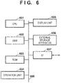
- a CPU 601 executes processing using a computer program and data stored in a RAM 602 or a ROM 603. By this, the CPU 601 performs operation control of the computer apparatus overall, and also executes or controls all processing described above as something that the image processing apparatus 3 performs.
- the RAM 602 has an area for storing computer programs and data loaded from the ROM 603 or an external storage apparatus 606 and data received from outside via an I/F (interface) 607. Furthermore, the RAM 602 also has a work area used when the CPU 601 executes various processing. In this way, the RAM 602 can provide various areas as necessary. Setting data of the image processing apparatus 3 and a boot program which do not need to be rewritten are stored in the ROM 603.
- An operation unit 604 is configured by a mouse, a keyboard, or the like, and the user of the image processing apparatus 3 can input various instructions to the CPU 601 by operating it.
- a display unit 605 is configured by a CRT, a liquid crystal screen, or the like, and can display results of processing by the CPU 601 using image, text, or the like. Note that a touch panel screen may be configured to integrate the operation unit 604 and the display unit 605.
- the external storage apparatus 606 is a large capacity information storage device as typified by a hard disk drive device.
- An OS operating system
- computer programs for causing the CPU 601 to execute or control each process described above as something that the image processing apparatus 3 performs, and data is saved in the external storage apparatus 606.
- This data includes what was described above as information known beforehand.
- a computer program or data saved in the external storage apparatus 606 is appropriately loaded to the RAM 602 in accordance with control by the CPU 601, and becomes a target of processing by the CPU 601.
- the recording unit 6 described above can be implemented by the RAM 602 or the external storage apparatus 606.
- An I/F 607 functions as an interface for performing data communication with an external device, and, for example, the aforementioned cameras 2 are connected to the I/F 607, and the images from each of the cameras 2 are received via the I/F 607.
- Each of the CPU 601, the RAM 602, the ROM 603, the operation unit 604, the display unit 605, the external storage apparatus 606, and the I/F 607 are connected to a bus 608. Note that the configuration illustrated in FIG. 6 is merely an example of a hardware configuration of a computer apparatus applied to the image processing apparatus 3.
- step S115 the CPU 601 saves captured images of each of the cameras 2 received via the I/F 607 in the external storage apparatus 606.
- step S116 the CPU 601 reads into the RAM 602 a captured image required for generation of a virtual viewpoint image from the external storage apparatus 606.
- step S117 the CPU 601 performs processing that is the same as processing by the detection unit 8 for the captured images that are respectively read out into the RAM 602.
- step S118 the CPU 601 performs processing that is similar to the processing by the detection unit 10.
- step S119 the CPU 601 determines whether or not occlusion is occurring between objects in captured images (the captured image A and the captured image B) required for generation of the virtual viewpoint image. If the result of the determination is that occlusion is occurring, the processing advances to step S121, and if occlusion is not occurring, the processing advances to step S120.
- step S120 the CPU 601 acquires a texture of an object detected in the captured image A. Meanwhile, in step S121, the CPU 601 generates a combination object by processing similar to the processing by the combining unit 11.
- step S122 the CPU 601 obtains a position at which to arrange the object in the virtual viewpoint image, and in step S123 the CPU 601 generates the background portion in the virtual viewpoint image similarly to the generating unit 9. Then, in step S124, the CPU 601 generates the virtual viewpoint image in which the object is arranged at the position obtained in step S122, and outputs the virtual viewpoint image.
- Embodiment(s) of the present invention can also be realized by a computer of a system or apparatus that reads out and executes computer executable instructions (e.g., one or more programs) recorded on a storage medium (which may also be referred to more fully as a 'non-transitory computer-readable storage medium') to perform the functions of one or more of the above-described embodiment(s) and/or that includes one or more circuits (e.g., application specific integrated circuit (ASIC)) for performing the functions of one or more of the above-described embodiment(s), and by a method performed by the computer of the system or apparatus by, for example, reading out and executing the computer executable instructions from the storage medium to perform the functions of one or more of the above-described embodiment(s) and/or controlling the one or more circuits to perform the functions of one or more of the above-described embodiment(s).
- computer executable instructions e.g., one or more programs
- a storage medium which may also be referred to more fully as
- the computer may comprise one or more processors (e.g., central processing unit (CPU), micro processing unit (MPU)) and may include a network of separate computers or separate processors to read out and execute the computer executable instructions.
- the computer executable instructions may be provided to the computer, for example, from a network or the storage medium.
- the storage medium may include, for example, one or more of a hard disk, a random-access memory (RAM), a read only memory (ROM), a storage of distributed computing systems, an optical disk (such as a compact disc (CD), digital versatile disc (DVD), or Blu-ray Disc (BD)TM), a flash memory device, a memory card, and the like.
Landscapes
- Engineering & Computer Science (AREA)
- Multimedia (AREA)
- Signal Processing (AREA)
- Computer Graphics (AREA)
- Physics & Mathematics (AREA)
- General Physics & Mathematics (AREA)
- Theoretical Computer Science (AREA)
- Studio Devices (AREA)
- Processing Or Creating Images (AREA)
- Image Generation (AREA)
- Closed-Circuit Television Systems (AREA)
- Image Analysis (AREA)
Description
- The present invention relates to a technique for generating a virtual viewpoint image from images captured from a plurality of viewpoints.
- In recent years, there has been an interest in techniques in which a plurality of cameras are installed at respectively different positions and synchronous capturing is performed at multiple view points, and using a plurality of viewpoint images (multiview images) obtained by the capturing, content (virtual viewpoint content) from the perspective of an arbitrary viewpoint (a virtual viewpoint) is generated. Because it is possible to view, for example, soccer and basketball highlight scenes from various angles by techniques that generate virtual viewpoint content from multiview images in this way, the user can be given a better viewing experience than with normal images.
- Meanwhile, generation and viewing of virtual viewpoint content based on multiview images can be realized by compiling images that a plurality of cameras captured in an image processing unit of a server or the like, applying processing such as rendering in the image processing unit, and ultimately transmitting images to a user terminal.
- A technique for generating virtual viewpoint video is described in Japanese Patent Laid-Open No.
2011-170487 2011-170487 - In Japanese Patent Laid-Open No.
2014-120093 - However, there are respective problems with the methods of Japanese Patent Laid-Open No.
2014-120093 - Also, upon performance of processing for acquiring an object from video of a viewpoint other than the viewpoint in which the occlusion is occurring, an object of significantly different orientation with respect to the virtual viewpoint is more likely to be acquired. The further the position is from the virtual viewpoint, the greater the difference from the actual object shape becomes, and the larger the influence on image quality becomes.
- Also, in processing for acquiring an object from a different frame, there is the problem that the longer the time over which the occlusion occurs, the larger the difference in time of the acquired object becomes and the larger the influence on image quality becomes.
- As prior art there may be mentioned:
COOKE E ET AL: "Scalable Virtual Viewpoint Image Synthesis for Multiple Camera Environments", INFORMATION VISUALISATION, 2005. PROCEEDINGS. NINTH INTERNATIONAL CONFERENCE ON LONDON ENGLAND 06-08 JULY 2005, PISCATAWAY, NJ, USA, IEEE, 6 July 2005 (2005-07-06), pages 393-397, XP010836360, ISBN: 978-0-7695-2397-2, which discloses a view synthesis algorithm that provides a scalable and flexible approach to virtual viewpoint synthesis in multiple camera environments. A multi-view synthesis (MVS) process consists of four different phases that are described in detail: surface identification, surface selection, surface boundary blending and surface reconstruction. MVS view synthesis identifies and selects only the best quality surface areas from the set of available reference images, thereby reducing perceptual errors in virtual view reconstruction. The approach is camera setup independent and scalable as virtual views can be created given 1 to N of the available video inputs. Thus, MVS provides interactive AV applications with a means to handle scenarios where camera inputs increase or decrease over time. - The present invention in its first aspect provides an image processing apparatus as specified in claims 1 to 8.
- The present invention in its second aspect provides an image generation method as specified in
claim 9. - The present invention in its third aspect provides a program as specified in
claim 10. - The present invention in its fourth aspect provides a computer-readable storage medium as specified in
claim 11. - Further features of the present invention will become apparent from the following description of exemplary embodiments (with reference to the attached drawings).
-
-
FIG. 1 is a view illustrating a use environment of a system. -
FIGS. 2A-2D are views for illustrating examples of captured images. -
FIG. 3 is a block diagram illustrating an example of a functional configuration of an image processing apparatus 3. -
FIGS. 4A-4C are flowcharts for processing that the image processing apparatus 3 performs. -
FIG. 5 is a flowchart for processing that a computer apparatus performs. -
FIG. 6 is a block diagram that illustrates an example of a hardware configuration of the computer apparatus. - Below, explanation will be given for embodiments of present invention with reference to the accompanying drawing. Note that embodiments described below merely illustrate examples of specifically implementing the present invention, and are only specific embodiments of a configuration defined in the scope of the claims.
- In the present embodiment, explanation is given of an example of an image processing apparatus for generating virtual viewpoint content. Virtual viewpoint content in the present embodiment is content that includes a virtual viewpoint image generated by simulating an image obtained when a subject is captured from a virtual viewpoint. A viewpoint that is virtual (a virtual viewpoint) may be designated by a user (operator), and it may be automatically designated based on a result of image analysis or the like. Configuration may also be taken such that virtual viewpoint sound generated by simulating the sound that would be heard from the virtual viewpoint is included in the virtual viewpoint content of the present embodiment. In the present embodiment, a method of generating a virtual viewpoint image is described in detail below.
- Also, the image processing apparatus of the present embodiment specifies a camera viewpoint for which occlusion of an object is not occurring out of the plurality of camera viewpoints corresponding to the plurality of cameras for capturing a subject from a plurality of viewpoints. Then, the image processing apparatus generates a combination object by object combination in the image captured from the specified camera viewpoint, to generate an image including the combination object as an image of the virtual viewpoint.
- Note that occlusion is a state in which objects such as people are overlapping, and a closer object is hiding a part of a farther object. Also, in the present embodiment, concepts encompassing video and still images are described using the expression "images". Specifically, each constituent element of the present embodiment can be processed regardless of whether the image is in accordance with a video format or in accordance with a still image format.
- First, a use environment of a system according to the present embodiment will be described using
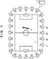
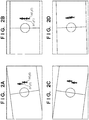
FIG. 1 . As is illustrated inFIG. 1 , a plurality ofcameras 2 are arranged around a stadium 1, and the stadium 1 is captured from a plurality of directions. Thecameras 2 comprise input/output hardware for data transmission. Thecameras 2 are connected in a ring-formation to each other using network cable, for example, and via a network, transmit images to thecamera 2 that is their neighbor. One of thecameras 2 is connected to the image processing apparatus 3, and all of the images of thecameras 2 are transmitted to the image processing apparatus 3. Note that configuration for transmitting all of the images of thecameras 2 to the image processing apparatus 3 are not limited to the above described configuration. Also, a sport such as soccer is played in the stadium 1, and a plurality of people 4 are present as subjects (objects) in the stadium 1. Here, examples of the images (captured images) that are captured by each of thecamera 2A, thecamera 2B, and thecamera 2C are illustrated inFIG. 2A-FIG. 2C . Thecamera 2A, thecamera 2B, and thecamera 2C are each at viewpoints that are close to each other, but as shown inFIGS. 2A-2C , images whose viewpoints are slightly differing are obtained because they are positioned at close but different positions to each other. - The image processing apparatus 3 receives each of the
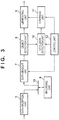
cameras 2 images, and generates an image (a virtual viewpoint image) at a virtual viewpoint using some of images of thecameras 2. An example of a functional configuration of the image processing apparatus 3 is described using the block diagram ofFIG. 3 . In the present embodiment, an example in which the functional units described inFIG. 3 are implemented by hardware such as an ASIC (Application Specific Integrated Circuit) or an FPGA (Field Programmable Gate Array) integrated in the image processing apparatus 3 is mainly described. However, the functional units illustrated inFIG. 3 may be realized using a CPU. Acontrol unit 12 performs control of operation of each of the functional units of the image processing apparatus 3 described below. - A
data reception unit 5 receives images transmitted from each of thecameras 2, and records in arecording unit 6 images of each frame (captured images) that configure the received images. Also, thedata reception unit 5 acquires virtual viewpoint information including information related to virtual viewpoint position and direction. The virtual viewpoint information may be acquired via a user interface, or may be decided automatically in accordance with the content of images (motion of a player, for example). Therecording unit 6 is connected to adata bus 13, and each functional unit can read or write data with respect to therecording unit 6 via thedata bus 13. - The
recording unit 6 is a storage device configured by, for example, a hard disk, an SSD (Solid State Drive), or a combination thereof. Adata readout unit 7 reads out, from therecording unit 6, a captured image that another functional unit made a request for because the captured image is necessary for generating a virtual viewpoint image. - For example, assume that an instruction (generation instruction) to cause the image processing apparatus 3 to generate a virtual viewpoint image at a virtual viewpoint close to the
camera 2A and thecamera 2B was made to the image processing apparatus 3. A generation instruction is inputted into the image processing apparatus 3 by a user operating an input interface connected to the image processing apparatus 3, for example. Also, in the foregoing generation instruction is included virtual viewpoint information which includes information related to virtual viewpoint position and direction. However, configuration may also be taken such that a generation instruction and virtual viewpoint information are acquired separately. - The
data readout unit 7, having accepted the foregoing generation instruction, reads out, from therecording unit 6, a captured image A that is captured by thecamera 2A and a captured image B (captured image of a frame of the same timing as the captured image A) captured by thecamera 2B. Specifically, thedata readout unit 7 reads out the captured images of thecamera 2A and thecamera 2B (captured image A and captured image B) which are selected based on information related to the position and direction of the virtual viewpoint from among a plurality of cameras (the 24 cameras illustrated inFIG. 1 ). Note that below it is assumed that "the same timing" is something that "may include an error if it is small enough that it can be treated as the same timing". The captured image A is the captured image illustrated inFIG. 2A , for example, and the captured image B is the captured image illustrated inFIG. 2B , for example. Next, thedata readout unit 7 outputs the read out captured image A and captured image B to an object detection unit 8 (hereinafter referred to as the detection unit 8). - The
detection unit 8 separates the captured images into a region of objects (foreground region) and a region of the background (background region) by detecting the objects from each of the captured image A and the captured image B. This separation may be performed using background difference information, for example. This is a method of generating background information based on information of images that were captured in the past within a fixed period of time, and treating a difference from the current captured image as an object. Various object detection methods using background difference information are known and so detailed description thereof is omitted. Regarding object detection, methods using feature amounts or machine learning are also known, and these methods may of course also be employed. - Assume that the captured image A is the captured image illustrated in
FIG. 2A . Here, thedetection unit 8 detects two objects in the captured image, and obtains the positions at which they are detected (a position of the bottom edge of the region of the object, for example). In the case ofFIG. 2A , the position at which one object is detected is (x1, y1), and the position at which the other object is detected is (x0, y0). Also, assume that the captured image B is the captured image illustrated inFIG. 2B . In this captured image, the two objects are overlapping (that is, occlusion between the objects in the captured image is occurring), and here thedetection unit 8 detects the two objects as a single object. - Then the
detection unit 8 outputs the image (texture) in the region of the detected object, a position at which an object is detected, and an image in the background region (a background image) for each of the captured image A and the captured image B. - An occlusion detection unit 10 (hereinafter referred to as the detection unit 10) determines whether or not occlusion is occurring between the objects in the captured image for each of the captured image A and the captured image B. Specifically, the
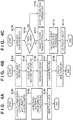
occlusion detection unit 10 executes occlusion detection processing with respect to images (the captured images A and B) captured by one or more cameras selected based on the virtual viewpoint information from out of a plurality of cameras (the 24 cameras illustrated inFIG. 1 ). Processing for determining whether or not occlusion is occurring between the objects in the captured image B is described usingFIG. 4A which illustrates a flowchart for the same processing as a concrete example of a method of processing for detecting occlusion. Note that processing for determining whether or not occlusion is occurring between objects is similarly performed for the captured image A and other captured images. - In step S101, the
detection unit 10 acquires the position at which the object in the image (frame of the same timing as the captured image B) captured by the camera positioned at a position close to the camera (thecamera 2B) that captured the captured image B was detected. Here, the position at which the object is detected in the captured image A which is captured by thecamera 2A adjacent to thecamera 2B is acquired. In the case ofFIG. 2A , the detection positions (x1, y1) and (x0, y0) are acquired. - In step S102, the
detection unit 10 transforms the detection positions acquired in step S101 to the positions on the captured image B by "a perspective transformation that causes a portion of the field (the ground) that appears in the image that thecamera 2A captures to match a field portion in the image that thecamera 2B captures. The perspective transformation is executed by a matrix computation, but the parameters of the matrix used in this matrix computation are decided in advance by a calibration process at a time of camera installation or the like, and held in the memory of the image processing apparatus 3. In the case ofFIG. 2A , by transforming the detection positions (x1, y1) and (x0, y0) by perspective transformation the positions (x1', y1') and (x0', y0') in the captured image B as is illustrated inFIG. 2B are respectively acquired. - In step S103, the
detection unit 10 determines whether or not two or more positions transformed in step S102 are included in a region of a single object in the captured image B. If the result of the determination is that the condition that "two or more positions transformed in step S102 are included in the region of a single object in the captured image B" is satisfied, it is possible to determine that occlusion between objects is occurring in the captured image B. Specifically, thedetection unit 10 transforms the positions of the plurality of objects in the image (the captured image A) captured from the first camera viewpoint among the plurality of camera viewpoints to positions in the image (the captured image B) captured from the viewpoint of the second camera. Then thedetection unit 10 determines that occlusion is occurring in the captured image B if the positions of the plurality of objects after the transformation corresponds to less objects. Meanwhile, if this condition is not satisfied, it can be determined that occlusion is not occurring between objects in the captured image B. In the case ofFIG. 2B , both the transformed detection positions (x1', y1') and (x0', y0') are included in the region of a single object in the captured image B, and so theocclusion detection unit 10 determines that occlusion is occurring between objects in the captured image B. - Note that in reality, considering error in the coordinate transformation, if two or more positions transformed in step S102 are positions that are close to the region of a single object in the captured image B, the two or more positions may be included in that region. In such a case, occlusion is determined to be occurring in the captured image B even if the positions in the captured image B corresponding to the positions at which two or more objects were detected in the captured image A are not included in the region of a single object in the captured image B.
- Here, if occlusion is determined to be occurring between the objects in the captured image B, the captured image B cannot be used in generation of the virtual viewpoint image at a virtual viewpoint close to the
camera 2A and thecamera 2B. Accordingly, an image that was captured by another camera (other than thecamera 2B) close to thecamera 2A is used in place of the captured image B. - Then if it is determined that occlusion is occurring in the captured image B, the
detection unit 8 makes an instruction to thedata readout unit 7 to cause it to read the image (the captured image of the frame of the same timing as the captured image A) captured by another camera (other than thecamera 2B) close to thecamera 2A. Here, in the explanation, a captured image C (a captured image of the frame of the same timing as the captured image A) captured by thecamera 2C is read. Specifically, thedata readout unit 7 reads the image (the captured image C) captured by the other camera in the case when it is determined that occlusion is occurring in the image (the captured image B) captured by the camera selected based on the virtual viewpoint information out of the plurality of cameras (the 24 cameras illustrated inFIG. 1 ). In this way, thedetection unit 8 can select thecamera 2C that becomes a replacement for thecamera 2B for which the occlusion is occurring from the plurality of cameras based on the distance from thecamera 2A. - Note that in the above description, an example in which the
camera 2C is selected based on the distance from thecamera 2A which was selected based on the virtual viewpoint information is described, but limitation is not made to this example. For example, configuration may be taken such that thedetection unit 8 selects thecamera 2C based on the distance from thecamera 2B for which occlusion is occurring. In such a case, thecamera 2C, which is the closest not yet selected camera from thecamera 2B, is selected. Also, for example, configuration may also be taken such that thedetection unit 8 specifies a not yet selected camera among the plurality of cameras (for example, the 24 cameras ofFIG. 1 ), thecamera 2C is selected as the closest camera to the position of the virtual viewpoint indicated by the virtual viewpoint information among the not yet selected cameras. - The
detection unit 8, by performing, with respect to the captured image C, processing similar to the processing described above that was performed with respect to the captured image A and the captured image B, detects an image (texture) in the region of an object, a position at which the object was detected, and an image (background image) in the background region from the captured image C. Then, thedetection unit 10 similarly determines whether or not occlusion is occurring between the objects in the captured image C. If the result of the determination is that thedetection unit 10 determines that occlusion is occurring between the objects in the captured image C as well, the image captured by another camera (other than thecamera 2B and thecamera 2C) close to thecamera 2A is read out. In this way, an image captured by a camera that is as close as possible to thecamera 2A that is a "captured image in which occlusion is not occurring between objects" is acquired. Below it is assumed that occlusion is not occurring between objects in the captured image C. In such a case, thedetection unit 8 outputs the information detected for the captured image A and the information detected for the captured image C. In this way, thedetection unit 8 of the present embodiment specifies a camera viewpoint at which occlusion (overlapping of objects) is not occurring from out of the plurality of camera viewpoints (viewpoints of the plurality of cameras illustrated inFIG. 1 ). - A combining
unit 11 performs processing for generating an object in an image from a virtual viewpoint. Processing that the combiningunit 11 performs is described usingFIG. 4B which illustrates a flowchart for the same processing. Note that the combiningunit 11 does not operate in a case when occlusion is not occurring between objects in the captured image B, and operates in a case when occlusion is occurring between objects in the captured image B. Specifically, the combiningunit 11 does not operate in a case when occlusion is not occurring between objects in the images captured by each of the cameras decided at the start as cameras close to the virtual viewpoint. Meanwhile, the combiningunit 11 does operate in a case when occlusion is occurring between objects in the image captured by at least one of the cameras that are decided to be cameras close to the virtual viewpoint from the beginning. - In step S104, the combining
unit 11 acquires information that thedetection unit 8 outputted for the captured image A and information thedetection unit 8 outputted for the captured image C. In step S105, the combiningunit 11 acquires the position of a virtual viewpoint included in the aforementioned generation instruction. - In step S106, the combining
unit 11 uses the position A of thecamera 2A, the position C of thecamera 2C, and the position V of the virtual viewpoint to obtain ratios (mixture ratios) at which to combine each object in the case of generating a single combination object by combining an object in the captured image A and an object in the captured image C. When, for example, the distance between the position V and the position A is made to be DA and the distance between the position V and the position C is made to be DC, the combination ratio RA for the object in the captured image A is DC/(DA + DC), and the combination ratio RC of the object in captured image C is DA/(DA + DC). That is, the combination ratios corresponding to the objects in the images captured in the cameras close to the virtual viewpoint are made to be higher, and the combination ratios corresponding to objects in images captured by cameras farther from the virtual viewpoint are made to be lower. - In step S107, the combining
unit 11 generates a combination texture (a combination object) by combining a texture A for which the pixel values of textures of objects in the captured image A are multiplied by RA and texture C for which the pixel values of the texture of the object in the captured image C are multiplied by RC. Such processing for combining the two object textures is a known technique as typified by morphing processing, and so detailed description thereof is omitted. In step S108, the combiningunit 11 outputs a combination object generated in step S107 to agenerating unit 9. - The generating
unit 9 generates a virtual viewpoint image. Processing that the generatingunit 9 performs is described usingFIG. 4C which illustrates a flowchart for the same processing. - In step S109, the generating
unit 9 generates a background portion for the virtual viewpoint image. The method of generating the background portion is not limited to a specific method. For example, the background image that thedetection unit 8 detected for the captured image A may be transformed by perspective transformation to generate the background portion for the virtual viewpoint image. It is assumed that the matrix used in this perspective transformation is known beforehand. - In step S110, the generating
unit 9 determines whether or not occlusion is occurring between objects in the images captured by two cameras that the virtual viewpoint is close to. In the foregoing example, it is determined whether or not occlusion is occurring between the objects in both the captured image A and the captured image B. If the result of the determination is that occlusion is not occurring between objects in either of the images captured by the two cameras that the virtual viewpoint is close to, the processing advances to step S111, and if it is occurring in at least one of them, the processing advances to step S112. - In step S111, the generating
unit 9 acquires from the detection unit 8 a texture of an object that thedetection unit 8 detected from the captured image A. In step S112, the generatingunit 9 acquires from the combiningunit 11 the combination object that the combiningunit 11 generated. - In step S113, the generating
unit 9 obtains the position of the object to be arranged on the virtual viewpoint image. In the case when the processing advances from step S111 to step S113, the generatingunit 9, in step S113, obtains "the arrangement position on the virtual viewpoint image" of the texture of the object detected from the captured image A. For example, it obtains in advance relation information indicating at what position a target object in an image captured by a camera appears in an image of a particular viewpoint, and obtains a position into which the position at which the object is detected in the captured image A is transformed using the relation information. - Meanwhile, in the case when the processing advances from step S112 to step S113, the generating
unit 9, in step S113, obtains the position of the combination object in the virtual viewpoint image. For example, the position into which the position at which the object is detected in the captured image A is transformed using the foregoing relation information is made to be the combination object position. - In the case when the processing advances from step S111 to step S114 via step S113, the generating
unit 9, in step S114, performs the following processing. Specifically, it arranges (re-projects) the texture of the object detected from the captured image A at the position (re-projection coordinates) obtained in step S113 in the virtual viewpoint image, and outputs the virtual viewpoint image after the arrangement. - Meanwhile, in the case when the processing advances from step S112 to step S114 via step S113, the generating
unit 9, in step S114, performs the following processing. Specifically, it arranges (re-projects) the combination object at the position (re-projection coordinates) obtained in step S113 in the virtual viewpoint image, and outputs the virtual viewpoint image after the arrangement. - Note that here the re-projection coordinates of each object are inspected, re-projection is performed in order of depth from the farthest object in the image, which is in turn overwritten by closer objects. By this processing, it is possible to correctly express the in front/behind relationship in the display of the objects.
- An example of a virtual viewpoint image based on the captured image of
FIG. 2A and the captured image ofFIG. 2C is illustrated inFIG. 2D . The virtual viewpoint image ofFIG. 2D is a virtual viewpoint image generated in the case when a virtual viewpoint is set at an intermediate position between thecamera 2A and thecamera 2B. Also, the output destination of the virtual viewpoint image produced by the generatingunit 9 is not limited to any specific output destination, and, for example, output may be to a monitor or projector that the image processing apparatus 3 comprises, and output may be to an external terminal device. - Note that it is assumed that the information handled as information that is known beforehand in the present embodiment and the variation below (for example, the arrangement positions of each of the
cameras 2 and the foregoing relation information) is registered in a memory in the image processing apparatus 3 in advance. - Various forms can be considered for the aforementioned "instruction to cause the image processing apparatus 3 to generate a virtual viewpoint image at a virtual viewpoint close to the
camera 2A and thecamera 2B". For example, a diagram in which a layout diagram of each of thecameras 2 superimposed on an overhead view that overlooks the stadium 1 is displayed on a display unit to present it to the user and the user designates a particular position on the diagram as the position of the virtual viewpoint. Thecontrol unit 12 then selects a camera that is close to the position designated on the diagram. Also, in a case when the position of the virtual viewpoint is defined to be a center-point position between adjacent cameras, configuration may also be taken so as to set the center-point position of the two cameras as the virtual viewpoint position when the user designates two cameras on the aforementioned diagram. - Also, while each of the
cameras 2 is positioned to surround the stadium 1 in the first embodiment, the first embodiment can be similarly applied even in cases in which thecameras 2 are positioned to surround a field of an image capturing target other than a stadium 1. - In the first embodiment, all of the functional units described in
FIG. 3 are described as being implemented as hardware. However, configuration may be taken to implement therecording unit 6 by a memory, and to implement other functional units by software (computer programs). In such a case, it is possible to apply a computer apparatus capable of executing such software to the foregoing image processing apparatus 3. An example of a hardware configuration of a computer apparatus that can be applied to the image processing apparatus 3 is described using the block diagram ofFIG. 6 . - A
CPU 601 executes processing using a computer program and data stored in aRAM 602 or aROM 603. By this, theCPU 601 performs operation control of the computer apparatus overall, and also executes or controls all processing described above as something that the image processing apparatus 3 performs. - The
RAM 602 has an area for storing computer programs and data loaded from theROM 603 or anexternal storage apparatus 606 and data received from outside via an I/F (interface) 607. Furthermore, theRAM 602 also has a work area used when theCPU 601 executes various processing. In this way, theRAM 602 can provide various areas as necessary. Setting data of the image processing apparatus 3 and a boot program which do not need to be rewritten are stored in theROM 603. - An
operation unit 604 is configured by a mouse, a keyboard, or the like, and the user of the image processing apparatus 3 can input various instructions to theCPU 601 by operating it. Adisplay unit 605 is configured by a CRT, a liquid crystal screen, or the like, and can display results of processing by theCPU 601 using image, text, or the like. Note that a touch panel screen may be configured to integrate theoperation unit 604 and thedisplay unit 605. - The
external storage apparatus 606 is a large capacity information storage device as typified by a hard disk drive device. An OS (operating system), computer programs for causing theCPU 601 to execute or control each process described above as something that the image processing apparatus 3 performs, and data is saved in theexternal storage apparatus 606. This data includes what was described above as information known beforehand. A computer program or data saved in theexternal storage apparatus 606 is appropriately loaded to theRAM 602 in accordance with control by theCPU 601, and becomes a target of processing by theCPU 601. Therecording unit 6 described above can be implemented by theRAM 602 or theexternal storage apparatus 606. - An I/
F 607 functions as an interface for performing data communication with an external device, and, for example, theaforementioned cameras 2 are connected to the I/F 607, and the images from each of thecameras 2 are received via the I/F 607. - Each of the
CPU 601, theRAM 602, theROM 603, theoperation unit 604, thedisplay unit 605, theexternal storage apparatus 606, and the I/F 607 are connected to abus 608. Note that the configuration illustrated inFIG. 6 is merely an example of a hardware configuration of a computer apparatus applied to the image processing apparatus 3. - In a case when such a computer apparatus executes the processing of the image processing apparatus 3 described in the first embodiment, the computer apparatus performs processing in accordance with a flowchart described in
FIG. 5 . Note that the details of the processing in each step ofFIG. 5 was already discussed in the first embodiment, and so explanation is simplified here. - In step S115, the
CPU 601 saves captured images of each of thecameras 2 received via the I/F 607 in theexternal storage apparatus 606. In step S116, theCPU 601 reads into the RAM 602 a captured image required for generation of a virtual viewpoint image from theexternal storage apparatus 606. In step S117, theCPU 601 performs processing that is the same as processing by thedetection unit 8 for the captured images that are respectively read out into theRAM 602. In step S118, theCPU 601 performs processing that is similar to the processing by thedetection unit 10. - In step S119, the
CPU 601 determines whether or not occlusion is occurring between objects in captured images (the captured image A and the captured image B) required for generation of the virtual viewpoint image. If the result of the determination is that occlusion is occurring, the processing advances to step S121, and if occlusion is not occurring, the processing advances to step S120. - In step S120, the
CPU 601 acquires a texture of an object detected in the captured image A. Meanwhile, in step S121, theCPU 601 generates a combination object by processing similar to the processing by the combiningunit 11. - In step S122, the
CPU 601 obtains a position at which to arrange the object in the virtual viewpoint image, and in step S123 theCPU 601 generates the background portion in the virtual viewpoint image similarly to thegenerating unit 9. Then, in step S124, theCPU 601 generates the virtual viewpoint image in which the object is arranged at the position obtained in step S122, and outputs the virtual viewpoint image. - By virtue of the configuration of the present embodiment, it is possible to improve the image quality of a virtual viewpoint image in an environment in which occlusion can occur.
- Embodiment(s) of the present invention can also be realized by a computer of a system or apparatus that reads out and executes computer executable instructions (e.g., one or more programs) recorded on a storage medium (which may also be referred to more fully as a 'non-transitory computer-readable storage medium') to perform the functions of one or more of the above-described embodiment(s) and/or that includes one or more circuits (e.g., application specific integrated circuit (ASIC)) for performing the functions of one or more of the above-described embodiment(s), and by a method performed by the computer of the system or apparatus by, for example, reading out and executing the computer executable instructions from the storage medium to perform the functions of one or more of the above-described embodiment(s) and/or controlling the one or more circuits to perform the functions of one or more of the above-described embodiment(s). The computer may comprise one or more processors (e.g., central processing unit (CPU), micro processing unit (MPU)) and may include a network of separate computers or separate processors to read out and execute the computer executable instructions. The computer executable instructions may be provided to the computer, for example, from a network or the storage medium. The storage medium may include, for example, one or more of a hard disk, a random-access memory (RAM), a read only memory (ROM), a storage of distributed computing systems, an optical disk (such as a compact disc (CD), digital versatile disc (DVD), or Blu-ray Disc (BD)™), a flash memory device, a memory card, and the like.
- While the present invention has been described with reference to exemplary embodiments, it is to be understood that the invention is not limited to the disclosed exemplary embodiments. The scope of the invention is defined by the appended claims.
Claims (11)
- An image processing apparatus (3) that is configured to generate a virtual viewpoint image based on one or more captured images out of a plurality of captured images obtained by capturing by a plurality of cameras (2), the apparatus (FIG. 3; FIG. 6) comprising:acquisition means (11; 601) configured to acquire (S105) virtual viewpoint information including information related to a position of a virtual viewpoint and a direction of view from the virtual viewpoint;determination means (10; 601) configured to determine (S103, S110; S118, S119), based on positions of objects detected in images captured at the same time respectively from a first viewpoint by a first camera (2A) and from a second viewpoint by a second camera (2B) and based on a transformation of the positions of the objects in the image captured from the first viewpoint to positions in the image captured from the second viewpoint, whether occlusion is occurring , wherein the first camera and the second camera are selected based on the virtual viewpoint information;
wherein the apparatus is further characterised by:decision means (9; 601) configured to decide (S113; S122; S123), based on a distance from the first camera (2A) to a third camera (2C) which is different to the second camera (2B) among the plurality of cameras (2), an image captured from the first viewpoint by the first camera (2A) and an image captured at the same time from a third viewpoint by the third camera (2C) as captured images to be used for generation of a virtual viewpoint image that is based on the virtual viewpoint information, in a case where it is determined by the determination means (10; 601) that occlusion is occurring in at least one image captured from the second viewpoint by the second camera (2B); andgeneration means (9; 601) configured to generate (S114; S124) a virtual viewpoint image that is based on the virtual viewpoint information using the captured images decided by the decision means (9; 601). - The image processing apparatus (3) according to claim 1, wherein, when the first camera (2A) and the second camera (2B) are selected from the plurality of cameras (2) based on the virtual viewpoint information acquired by the acquisition means (11; 601),
in a case when it is determined by the determination means (10; 601) that occlusion is occurring in at least one image captured from the second viewpoint by the second camera (2B), the decision means selects the third camera (2C) from the plurality of cameras (2); and
in a case when it is determined by the determination means (10; 601) that occlusion is not occurring in at least one image captured from the third viewpoint by the selected third camera (2C), the decision means (9; 601) is configured to decide that an image captured from the first viewpoint by the first camera (2A) and an image captured from the third viewpoint by the third camera (2C) are captured images that should be used for generation of the virtual viewpoint image. - The image processing apparatus (3) according to claim 2, wherein the decision means (9; 601) is configured to select the third camera (2C) from the plurality of cameras (2) based on the virtual viewpoint information acquired by the acquisition means (11; 601).
- The image processing apparatus (3) according to any preceding claim, wherein in a case when transformed positions of a plurality of objects, the transformed positions being obtained by transforming positions of the plurality of objects in an image captured from the first viewpoint by the first camera (2A) among the plurality of cameras (2) into positions in an image captured from the second viewpoint by the second camera (2B) among the plurality of cameras (2), correspond to a lower number of objects than the plurality of objects in the image captured from the second viewpoint by the second camera (2B), the determination means (10; 601) is configured to determine that occlusion is occurring in the image captured from the second viewpoint by the second camera (2B).
- The image processing apparatus (3) according to claim 4, wherein in a case when a result of the transformation of the positions of the plurality of objects does not correspond to a lower number of objects than the plurality of objects in the image captured from the second viewpoint by the second camera (2B), the determination means (10; 601) is configured to determine that occlusion is not occurring in the image captured from the second viewpoint by the second camera (2B).
- The image processing apparatus (3) according to any preceding claim, wherein the decision means (9; 601) is configured to decide that a captured image in which occlusion is determined to be occurring by the determination means (10; 601) is not to be used in generation of the virtual viewpoint image.
- The image processing apparatus (3) according to any preceding claim, wherein the generation means (9; 601) is configured to generate the virtual viewpoint image by combining objects in the plurality of captured images decided by the decision means (9; 601), based on a combination ratio according to a distance between the position of the virtual viewpoint and a viewpoint position of a camera that captured the captured image that the decision means (9; 601) decided.
- The image processing apparatus (3) according to any preceding claim, wherein the plurality of cameras (2) are positioned so as to surround an image capturing target field.
- An image generation method of generating a virtual viewpoint image based on one or more captured images out of a plurality of captured images obtained by capturing by a plurality of cameras (2), the method comprising:acquiring (S105) virtual viewpoint information including information related to a position of a virtual viewpoint and a direction of view from the virtual viewpoint;determining (S103, S110; S118, S119), based on positions of objects detected in images captured at the same time respectively from a first viewpoint by a first camera (2A) and from a second viewpoint by a second camera (2B) and based on a transformation of the positions of the objects in the image captured from the first viewpoint to positions in the image captured from the second viewpoint, whether occlusion is occurring , wherein the first camera and the second camera are selected based on the virtual viewpoint information;characterised such that based on a distance from the first camera (2A) to a third camera (2C) which is different to the second camera (2B) among the plurality of cameras (2), deciding (S113; S122, S123) an image captured from the first viewpoint by the first camera (2A) and an image captured at the same time from a third viewpoint by the third camera (2C) as captured images to be used for generation of a virtual viewpoint image that is based on the virtual viewpoint information, in a case where it is determined that occlusion is occurring in at least one image captured from the second viewpoint by the second camera (2B); andgenerating (S114; S124) a virtual viewpoint image that is based on the virtual viewpoint information using the decided captured images.
- A computer program comprising instructions which, when the program is executed by a computer, cause the computer to carry out the method of claim 9.
- A computer-readable storage medium comprising instructions which, when executed by a computer, cause the computer to carry out the method of claim 9.
Applications Claiming Priority (1)
| Application Number | Priority Date | Filing Date | Title |
|---|---|---|---|
| JP2016158912A JP6882868B2 (en) | 2016-08-12 | 2016-08-12 | Image processing equipment, image processing method, system |
Publications (2)
| Publication Number | Publication Date |
|---|---|
| EP3285484A1 EP3285484A1 (en) | 2018-02-21 |
| EP3285484B1 true EP3285484B1 (en) | 2021-05-26 |
Family
ID=59745166
Family Applications (1)
| Application Number | Title | Priority Date | Filing Date |
|---|---|---|---|
| EP17185816.0A Active EP3285484B1 (en) | 2016-08-12 | 2017-08-10 | Image processing apparatus, image generation method, and program |
Country Status (3)
| Country | Link |
|---|---|
| US (1) | US10244163B2 (en) |
| EP (1) | EP3285484B1 (en) |
| JP (1) | JP6882868B2 (en) |
Families Citing this family (14)
| Publication number | Priority date | Publication date | Assignee | Title |
|---|---|---|---|---|
| JP7159057B2 (en) * | 2017-02-10 | 2022-10-24 | パナソニック インテレクチュアル プロパティ コーポレーション オブ アメリカ | Free-viewpoint video generation method and free-viewpoint video generation system |
| JP7030452B2 (en) * | 2017-08-30 | 2022-03-07 | キヤノン株式会社 | Information processing equipment, information processing device control methods, information processing systems and programs |
| KR102178239B1 (en) * | 2017-12-14 | 2020-11-12 | 캐논 가부시끼가이샤 | 3D model generation device, generation method, and program |
| JP7132730B2 (en) * | 2018-03-14 | 2022-09-07 | キヤノン株式会社 | Information processing device and information processing method |
| JP7374582B2 (en) * | 2018-11-27 | 2023-11-07 | キヤノン株式会社 | Image processing device, image generation method and program |
| US10818077B2 (en) * | 2018-12-14 | 2020-10-27 | Canon Kabushiki Kaisha | Method, system and apparatus for controlling a virtual camera |
| CN110798673B (en) * | 2019-11-13 | 2021-03-19 | 南京大学 | Free viewpoint video generation and interaction method based on deep convolutional neural network |
| WO2021131375A1 (en) * | 2019-12-26 | 2021-07-01 | 富士フイルム株式会社 | Information processing device, information processing method, and program |
| JP7427467B2 (en) * | 2020-02-14 | 2024-02-05 | キヤノン株式会社 | Image processing device, image processing method, trained model generation method, and program |
| JP7427468B2 (en) * | 2020-02-18 | 2024-02-05 | キヤノン株式会社 | Information processing device, information processing method, and program |
| US12003806B2 (en) * | 2021-03-11 | 2024-06-04 | Quintar, Inc. | Augmented reality system for viewing an event with multiple coordinate systems and automatically generated model |
| JP7775140B2 (en) * | 2022-05-12 | 2025-11-25 | キヤノン株式会社 | Image processing device, image processing method and program |
| JP2024031427A (en) * | 2022-08-26 | 2024-03-07 | 株式会社Jvcケンウッド | Content sales device, content sales method, and content sales program |
| JP2024062300A (en) * | 2022-10-24 | 2024-05-09 | キヤノン株式会社 | Image processing device, image processing method, and computer program |
Family Cites Families (4)
| Publication number | Priority date | Publication date | Assignee | Title |
|---|---|---|---|---|
| US8154633B2 (en) * | 2007-11-16 | 2012-04-10 | Sportvision, Inc. | Line removal and object detection in an image |
| JP5366258B2 (en) * | 2010-02-17 | 2013-12-11 | Kddi株式会社 | Virtual viewpoint image generation method and program based on geometric information in large space camera arrangement |
| JP5969376B2 (en) | 2012-12-19 | 2016-08-17 | Kddi株式会社 | Virtual viewpoint video generation device, virtual viewpoint video generation method, and program |
| JP6201476B2 (en) * | 2013-07-18 | 2017-09-27 | 凸版印刷株式会社 | Free viewpoint image capturing apparatus and method |
-
2016
- 2016-08-12 JP JP2016158912A patent/JP6882868B2/en active Active
-
2017
- 2017-07-28 US US15/663,163 patent/US10244163B2/en active Active
- 2017-08-10 EP EP17185816.0A patent/EP3285484B1/en active Active
Non-Patent Citations (1)
| Title |
|---|
| None * |
Also Published As
| Publication number | Publication date |
|---|---|
| EP3285484A1 (en) | 2018-02-21 |
| US20180048810A1 (en) | 2018-02-15 |
| JP6882868B2 (en) | 2021-06-02 |
| US10244163B2 (en) | 2019-03-26 |
| JP2018026064A (en) | 2018-02-15 |
Similar Documents
| Publication | Publication Date | Title |
|---|---|---|
| EP3285484B1 (en) | Image processing apparatus, image generation method, and program | |
| US11589023B2 (en) | Image processing apparatus, image processing method, and storage medium | |
| US9846960B2 (en) | Automated camera array calibration | |
| US10785469B2 (en) | Generation apparatus and method for generating a virtual viewpoint image | |
| KR102350235B1 (en) | Image processing method and apparatus thereof | |
| US11839721B2 (en) | Information processing apparatus, information processing method, and storage medium | |
| JP4879326B2 (en) | System and method for synthesizing a three-dimensional image | |
| RU2720356C1 (en) | Control device, control method and storage medium | |
| US10769849B2 (en) | Use of temporal motion vectors for 3D reconstruction | |
| JP7664891B2 (en) | Method for generating layered depth data of a scene - Patents.com | |
| JP7285834B2 (en) | Three-dimensional reconstruction method and three-dimensional reconstruction apparatus | |
| JP7017175B2 (en) | Information processing equipment, information processing method, program | |
| JP2019075082A (en) | Video processing method and device using depth value estimation | |
| US10951873B2 (en) | Information processing apparatus, information processing method, and storage medium | |
| KR102129458B1 (en) | Method for reconstructing three dimension information of object and apparatus for the same | |
| US10535147B2 (en) | Electronic apparatus and method for processing image thereof | |
| US11076140B2 (en) | Information processing apparatus and method of controlling the same | |
| US12374066B2 (en) | Information processing apparatus, information processing method, and medium | |
| CN110520902B (en) | Method and device for applying dynamic effects to images | |
| EP4350626B1 (en) | Image processing system, method for controlling the same, and program | |
| WO2020193703A1 (en) | Techniques for detection of real-time occlusion | |
| US20240372971A1 (en) | Information processing apparatus, information processing method, data structure, and non-transitory computer-readable medium | |
| US12526392B2 (en) | Information processing apparatus and method, and storage medium for generating arbitrary viewpoint images | |
| KR101849696B1 (en) | Method and apparatus for obtaining informaiton of lighting and material in image modeling system | |
| JP7012457B2 (en) | Image processing device, image processing method |
Legal Events
| Date | Code | Title | Description |
|---|---|---|---|
| PUAI | Public reference made under article 153(3) epc to a published international application that has entered the european phase |
Free format text: ORIGINAL CODE: 0009012 |
|
| STAA | Information on the status of an ep patent application or granted ep patent |
Free format text: STATUS: THE APPLICATION HAS BEEN PUBLISHED |
|
| AK | Designated contracting states |
Kind code of ref document: A1 Designated state(s): AL AT BE BG CH CY CZ DE DK EE ES FI FR GB GR HR HU IE IS IT LI LT LU LV MC MK MT NL NO PL PT RO RS SE SI SK SM TR |
|
| AX | Request for extension of the european patent |
Extension state: BA ME |
|
| STAA | Information on the status of an ep patent application or granted ep patent |
Free format text: STATUS: REQUEST FOR EXAMINATION WAS MADE |
|
| 17P | Request for examination filed |
Effective date: 20180821 |
|
| RBV | Designated contracting states (corrected) |
Designated state(s): AL AT BE BG CH CY CZ DE DK EE ES FI FR GB GR HR HU IE IS IT LI LT LU LV MC MK MT NL NO PL PT RO RS SE SI SK SM TR |
|
| STAA | Information on the status of an ep patent application or granted ep patent |
Free format text: STATUS: EXAMINATION IS IN PROGRESS |
|
| 17Q | First examination report despatched |
Effective date: 20200511 |
|
| REG | Reference to a national code |
Ref country code: DE Ref legal event code: R079 Ref document number: 602017039147 Country of ref document: DE Free format text: PREVIOUS MAIN CLASS: H04N0013000000 Ipc: H04N0013111000 |
|
| GRAP | Despatch of communication of intention to grant a patent |
Free format text: ORIGINAL CODE: EPIDOSNIGR1 |
|
| STAA | Information on the status of an ep patent application or granted ep patent |
Free format text: STATUS: GRANT OF PATENT IS INTENDED |
|
| RIC1 | Information provided on ipc code assigned before grant |
Ipc: H04N 13/117 20180101ALI20201113BHEP Ipc: G06T 15/00 20110101ALI20201113BHEP Ipc: H04N 13/111 20180101AFI20201113BHEP Ipc: H04N 13/243 20180101ALI20201113BHEP |
|
| INTG | Intention to grant announced |
Effective date: 20201208 |
|
| GRAS | Grant fee paid |
Free format text: ORIGINAL CODE: EPIDOSNIGR3 |
|
| GRAA | (expected) grant |
Free format text: ORIGINAL CODE: 0009210 |
|
| STAA | Information on the status of an ep patent application or granted ep patent |
Free format text: STATUS: THE PATENT HAS BEEN GRANTED |
|
| AK | Designated contracting states |
Kind code of ref document: B1 Designated state(s): AL AT BE BG CH CY CZ DE DK EE ES FI FR GB GR HR HU IE IS IT LI LT LU LV MC MK MT NL NO PL PT RO RS SE SI SK SM TR |
|
| REG | Reference to a national code |
Ref country code: GB Ref legal event code: FG4D |
|
| REG | Reference to a national code |
Ref country code: CH Ref legal event code: EP |
|
| REG | Reference to a national code |
Ref country code: DE Ref legal event code: R096 Ref document number: 602017039147 Country of ref document: DE |
|
| REG | Reference to a national code |
Ref country code: AT Ref legal event code: REF Ref document number: 1397400 Country of ref document: AT Kind code of ref document: T Effective date: 20210615 |
|
| REG | Reference to a national code |
Ref country code: IE Ref legal event code: FG4D |
|
| REG | Reference to a national code |
Ref country code: LT Ref legal event code: MG9D |
|
| REG | Reference to a national code |
Ref country code: AT Ref legal event code: MK05 Ref document number: 1397400 Country of ref document: AT Kind code of ref document: T Effective date: 20210526 |
|
| PG25 | Lapsed in a contracting state [announced via postgrant information from national office to epo] |
Ref country code: HR Free format text: LAPSE BECAUSE OF FAILURE TO SUBMIT A TRANSLATION OF THE DESCRIPTION OR TO PAY THE FEE WITHIN THE PRESCRIBED TIME-LIMIT Effective date: 20210526 Ref country code: AT Free format text: LAPSE BECAUSE OF FAILURE TO SUBMIT A TRANSLATION OF THE DESCRIPTION OR TO PAY THE FEE WITHIN THE PRESCRIBED TIME-LIMIT Effective date: 20210526 Ref country code: BG Free format text: LAPSE BECAUSE OF FAILURE TO SUBMIT A TRANSLATION OF THE DESCRIPTION OR TO PAY THE FEE WITHIN THE PRESCRIBED TIME-LIMIT Effective date: 20210826 Ref country code: FI Free format text: LAPSE BECAUSE OF FAILURE TO SUBMIT A TRANSLATION OF THE DESCRIPTION OR TO PAY THE FEE WITHIN THE PRESCRIBED TIME-LIMIT Effective date: 20210526 Ref country code: LT Free format text: LAPSE BECAUSE OF FAILURE TO SUBMIT A TRANSLATION OF THE DESCRIPTION OR TO PAY THE FEE WITHIN THE PRESCRIBED TIME-LIMIT Effective date: 20210526 |
|
| REG | Reference to a national code |
Ref country code: NL Ref legal event code: MP Effective date: 20210526 |
|
| PG25 | Lapsed in a contracting state [announced via postgrant information from national office to epo] |
Ref country code: NO Free format text: LAPSE BECAUSE OF FAILURE TO SUBMIT A TRANSLATION OF THE DESCRIPTION OR TO PAY THE FEE WITHIN THE PRESCRIBED TIME-LIMIT Effective date: 20210826 Ref country code: PT Free format text: LAPSE BECAUSE OF FAILURE TO SUBMIT A TRANSLATION OF THE DESCRIPTION OR TO PAY THE FEE WITHIN THE PRESCRIBED TIME-LIMIT Effective date: 20210927 Ref country code: PL Free format text: LAPSE BECAUSE OF FAILURE TO SUBMIT A TRANSLATION OF THE DESCRIPTION OR TO PAY THE FEE WITHIN THE PRESCRIBED TIME-LIMIT Effective date: 20210526 Ref country code: RS Free format text: LAPSE BECAUSE OF FAILURE TO SUBMIT A TRANSLATION OF THE DESCRIPTION OR TO PAY THE FEE WITHIN THE PRESCRIBED TIME-LIMIT Effective date: 20210526 Ref country code: SE Free format text: LAPSE BECAUSE OF FAILURE TO SUBMIT A TRANSLATION OF THE DESCRIPTION OR TO PAY THE FEE WITHIN THE PRESCRIBED TIME-LIMIT Effective date: 20210526 Ref country code: LV Free format text: LAPSE BECAUSE OF FAILURE TO SUBMIT A TRANSLATION OF THE DESCRIPTION OR TO PAY THE FEE WITHIN THE PRESCRIBED TIME-LIMIT Effective date: 20210526 Ref country code: IS Free format text: LAPSE BECAUSE OF FAILURE TO SUBMIT A TRANSLATION OF THE DESCRIPTION OR TO PAY THE FEE WITHIN THE PRESCRIBED TIME-LIMIT Effective date: 20210926 Ref country code: GR Free format text: LAPSE BECAUSE OF FAILURE TO SUBMIT A TRANSLATION OF THE DESCRIPTION OR TO PAY THE FEE WITHIN THE PRESCRIBED TIME-LIMIT Effective date: 20210827 |
|
| PG25 | Lapsed in a contracting state [announced via postgrant information from national office to epo] |
Ref country code: NL Free format text: LAPSE BECAUSE OF FAILURE TO SUBMIT A TRANSLATION OF THE DESCRIPTION OR TO PAY THE FEE WITHIN THE PRESCRIBED TIME-LIMIT Effective date: 20210526 |
|
| PG25 | Lapsed in a contracting state [announced via postgrant information from national office to epo] |
Ref country code: RO Free format text: LAPSE BECAUSE OF FAILURE TO SUBMIT A TRANSLATION OF THE DESCRIPTION OR TO PAY THE FEE WITHIN THE PRESCRIBED TIME-LIMIT Effective date: 20210526 Ref country code: ES Free format text: LAPSE BECAUSE OF FAILURE TO SUBMIT A TRANSLATION OF THE DESCRIPTION OR TO PAY THE FEE WITHIN THE PRESCRIBED TIME-LIMIT Effective date: 20210526 Ref country code: CZ Free format text: LAPSE BECAUSE OF FAILURE TO SUBMIT A TRANSLATION OF THE DESCRIPTION OR TO PAY THE FEE WITHIN THE PRESCRIBED TIME-LIMIT Effective date: 20210526 Ref country code: DK Free format text: LAPSE BECAUSE OF FAILURE TO SUBMIT A TRANSLATION OF THE DESCRIPTION OR TO PAY THE FEE WITHIN THE PRESCRIBED TIME-LIMIT Effective date: 20210526 Ref country code: EE Free format text: LAPSE BECAUSE OF FAILURE TO SUBMIT A TRANSLATION OF THE DESCRIPTION OR TO PAY THE FEE WITHIN THE PRESCRIBED TIME-LIMIT Effective date: 20210526 Ref country code: SM Free format text: LAPSE BECAUSE OF FAILURE TO SUBMIT A TRANSLATION OF THE DESCRIPTION OR TO PAY THE FEE WITHIN THE PRESCRIBED TIME-LIMIT Effective date: 20210526 Ref country code: SK Free format text: LAPSE BECAUSE OF FAILURE TO SUBMIT A TRANSLATION OF THE DESCRIPTION OR TO PAY THE FEE WITHIN THE PRESCRIBED TIME-LIMIT Effective date: 20210526 |
|
| REG | Reference to a national code |
Ref country code: DE Ref legal event code: R119 Ref document number: 602017039147 Country of ref document: DE |
|
| REG | Reference to a national code |
Ref country code: CH Ref legal event code: PL |
|
| PLBE | No opposition filed within time limit |
Free format text: ORIGINAL CODE: 0009261 |
|
| STAA | Information on the status of an ep patent application or granted ep patent |
Free format text: STATUS: NO OPPOSITION FILED WITHIN TIME LIMIT |
|
| PG25 | Lapsed in a contracting state [announced via postgrant information from national office to epo] |
Ref country code: MC Free format text: LAPSE BECAUSE OF FAILURE TO SUBMIT A TRANSLATION OF THE DESCRIPTION OR TO PAY THE FEE WITHIN THE PRESCRIBED TIME-LIMIT Effective date: 20210526 |
|
| REG | Reference to a national code |
Ref country code: BE Ref legal event code: MM Effective date: 20210831 |
|
| PG25 | Lapsed in a contracting state [announced via postgrant information from national office to epo] |
Ref country code: LI Free format text: LAPSE BECAUSE OF NON-PAYMENT OF DUE FEES Effective date: 20210831 Ref country code: CH Free format text: LAPSE BECAUSE OF NON-PAYMENT OF DUE FEES Effective date: 20210831 |
|
| 26N | No opposition filed |
Effective date: 20220301 |
|
| PG25 | Lapsed in a contracting state [announced via postgrant information from national office to epo] |
Ref country code: IS Free format text: LAPSE BECAUSE OF FAILURE TO SUBMIT A TRANSLATION OF THE DESCRIPTION OR TO PAY THE FEE WITHIN THE PRESCRIBED TIME-LIMIT Effective date: 20210926 Ref country code: LU Free format text: LAPSE BECAUSE OF NON-PAYMENT OF DUE FEES Effective date: 20210810 Ref country code: AL Free format text: LAPSE BECAUSE OF FAILURE TO SUBMIT A TRANSLATION OF THE DESCRIPTION OR TO PAY THE FEE WITHIN THE PRESCRIBED TIME-LIMIT Effective date: 20210526 |
|
| PG25 | Lapsed in a contracting state [announced via postgrant information from national office to epo] |
Ref country code: IT Free format text: LAPSE BECAUSE OF FAILURE TO SUBMIT A TRANSLATION OF THE DESCRIPTION OR TO PAY THE FEE WITHIN THE PRESCRIBED TIME-LIMIT Effective date: 20210526 Ref country code: IE Free format text: LAPSE BECAUSE OF NON-PAYMENT OF DUE FEES Effective date: 20210810 Ref country code: FR Free format text: LAPSE BECAUSE OF NON-PAYMENT OF DUE FEES Effective date: 20210831 Ref country code: DE Free format text: LAPSE BECAUSE OF NON-PAYMENT OF DUE FEES Effective date: 20220301 Ref country code: BE Free format text: LAPSE BECAUSE OF NON-PAYMENT OF DUE FEES Effective date: 20210831 |
|
| PG25 | Lapsed in a contracting state [announced via postgrant information from national office to epo] |
Ref country code: HU Free format text: LAPSE BECAUSE OF FAILURE TO SUBMIT A TRANSLATION OF THE DESCRIPTION OR TO PAY THE FEE WITHIN THE PRESCRIBED TIME-LIMIT; INVALID AB INITIO Effective date: 20170810 |
|
| PG25 | Lapsed in a contracting state [announced via postgrant information from national office to epo] |
Ref country code: CY Free format text: LAPSE BECAUSE OF FAILURE TO SUBMIT A TRANSLATION OF THE DESCRIPTION OR TO PAY THE FEE WITHIN THE PRESCRIBED TIME-LIMIT Effective date: 20210526 |
|
| PG25 | Lapsed in a contracting state [announced via postgrant information from national office to epo] |
Ref country code: MK Free format text: LAPSE BECAUSE OF FAILURE TO SUBMIT A TRANSLATION OF THE DESCRIPTION OR TO PAY THE FEE WITHIN THE PRESCRIBED TIME-LIMIT Effective date: 20210526 |
|
| PG25 | Lapsed in a contracting state [announced via postgrant information from national office to epo] |
Ref country code: MT Free format text: LAPSE BECAUSE OF FAILURE TO SUBMIT A TRANSLATION OF THE DESCRIPTION OR TO PAY THE FEE WITHIN THE PRESCRIBED TIME-LIMIT Effective date: 20210526 |
|
| PGFP | Annual fee paid to national office [announced via postgrant information from national office to epo] |
Ref country code: GB Payment date: 20250725 Year of fee payment: 9 |
|
| PG25 | Lapsed in a contracting state [announced via postgrant information from national office to epo] |
Ref country code: TR Free format text: LAPSE BECAUSE OF FAILURE TO SUBMIT A TRANSLATION OF THE DESCRIPTION OR TO PAY THE FEE WITHIN THE PRESCRIBED TIME-LIMIT Effective date: 20210526 |