EP4350407A1 - Optical fiber cable, optical fiber cable manufacturing device, optical fiber cable manufacturing method, and optical fiber cable laying method - Google Patents
Optical fiber cable, optical fiber cable manufacturing device, optical fiber cable manufacturing method, and optical fiber cable laying method Download PDFInfo
- Publication number
- EP4350407A1 EP4350407A1 EP21944063.3A EP21944063A EP4350407A1 EP 4350407 A1 EP4350407 A1 EP 4350407A1 EP 21944063 A EP21944063 A EP 21944063A EP 4350407 A1 EP4350407 A1 EP 4350407A1
- Authority
- EP
- European Patent Office
- Prior art keywords
- optical fiber
- fiber cable
- outer cover
- impression
- convex portions
- Prior art date
- Legal status (The legal status is an assumption and is not a legal conclusion. Google has not performed a legal analysis and makes no representation as to the accuracy of the status listed.)
- Pending
Links
Images





Classifications
-
- G—PHYSICS
- G02—OPTICS
- G02B—OPTICAL ELEMENTS, SYSTEMS OR APPARATUS
- G02B6/00—Light guides; Structural details of arrangements comprising light guides and other optical elements, e.g. couplings
- G02B6/44—Mechanical structures for providing tensile strength and external protection for fibres, e.g. optical transmission cables
- G02B6/4479—Manufacturing methods of optical cables
- G02B6/4482—Code or colour marking
-
- G—PHYSICS
- G02—OPTICS
- G02B—OPTICAL ELEMENTS, SYSTEMS OR APPARATUS
- G02B6/00—Light guides; Structural details of arrangements comprising light guides and other optical elements, e.g. couplings
- G02B6/46—Processes or apparatus adapted for installing or repairing optical fibres or optical cables
Definitions
- the present disclosure relates to an optical fiber cable, an optical fiber cable manufacturing apparatus, an optical fiber cable manufacturing method, and an optical fiber cable laying method.
- Losses of an optical fiber transmission line include a loss generated in an optical fiber cable and a loss generated at a point connecting optical fiber cables.
- the latter loss can be expected to be reduced by reducing the number of connecting points on the transmission lines.
- Reducing the number of connecting points means laying long optical fiber cables.
- an optical fiber cable which realizes a small diameter and a light weight by abolishing a slot rod for housing and protecting an optical fiber has been developed and put into practical use (see, for example, PTL 1). Further, there is a likelihood that a longer optical fiber cable can be laid.
- an impression is marked on a surface of an outer cover to enable a constructor to know the type and the length of the cable that the constructor lays. Since the impression is in contact with an inner wall of a conduit or the like in laying the cable, it is necessary to mark the impression by a method strong enough to keep the impression from wearing off.
- an object of the present disclosure is to prevent an impression, marked on a side surface of an outer cover of an optical fiber cable, from wearing off caused by laying.
- a concave portion or a plurality of convex portions are provided on an outer edge of a cross section perpendicular to a long axis direction of an outer cover, and an impression is marked on the concave portion or on a portion sandwiched between the plurality of convex portions of the side surface of the outer cover.
- an optical fiber cable according to the present disclosure includes
- an optical fiber cable manufacturing apparatus includes
- the present disclosure provides a method for manufacturing an optical fiber cable, the method including: covering a cable core, having one or a plurality of optical fiber core wires therein, with an outer cover;
- the present disclosure provides a method for laying an optical fiber cable, the method including: selecting the optical fiber cable from a plurality of optical fiber cables, having different concave portions or a plurality of convex portions, for an outer edge of a cross section perpendicular to a long axis direction of at least a part of an outer cover, in accordance with a radius of curvature of an inner diameter of a cross section perpendicular to a long axis direction of a conduit for laying the optical fiber cable; and laying the selected optical fiber cable on an inner wall of the conduit.
- Fig. 1 shows a first embodiment of the present invention.
- Fig. 1 shows a cross section perpendicular to a long axis direction of an optical fiber cable 10.
- the optical fiber cable 10 includes a cable core 11 formed by assembling one or a plurality of coated optical fibers (not shown) therein, and an outer cover 12 that covers the cable core 11.
- An outer edge in the cross section perpendicular to the long axis direction of the outer cover 12 may have at least one set of two points 14a and 14b satisfying the following condition.
- the condition is described below: when the two points 14a and 14b are connected by a shortest curve 31 having a predetermined radius of curvature ⁇ and the curve 31 is connected to be convex toward the outside of the outer cover 12, the curve 31 is located outside the outer cover 12. That is, the condition is that two points 14a and 14b of the outer edge in the cross section perpendicular to the long axis direction of the outer cover 12 is in contact with the inside of the curve of the radius of curvature ⁇ .
- the radius of curvature ⁇ may be the radius of curvature of the inner diameter of the cross section perpendicular to the long axis direction of a conduit or the like 30 in which the optical fiber cable 10 is laid.
- a lower limit of the radius of curvature ⁇ is the radius of the optical fiber cable 10.
- the two points 14a and 14b shown in Fig. 1 can be realized by providing a concave portion or a plurality of convex portions for an outer edge of a cross section perpendicular to the long axis direction of the outer cover 12.
- the concave portion is a portion located inside an outer peripheral circle, around the outer cover 12, having the other portion 12b of the outer edge of the outer cover 12 as a circumference, and the two points 14a and 14b located at both ends of the concave portion are in contact with the inside of the curve of the radius of curvature ⁇ .
- the convex portions are portions located outside the outer peripheral circle, in the outer cover 12, having the other portion 12b of the outer edge of the outer cover 12 as a circumference.
- Fig. 1 shows an example in which the concave portion is formed for the outer edge of a cross section perpendicular to the long axis direction of the outer cover 12.
- a region sandwiched between the two points 14a and 14b on the surface of the outer cover 12 functions as a surface for impression marking on which the impression 13 is marked.
- Fig. 2 shows another example in which one portion 12a of the outer edge of a cross section perpendicular to the long axis direction of the outer cover 12 is a concave portion.
- the optical fiber cable 10 and the conduit or the like 30 shown in Fig. 2 are the same as those shown in Fig. 1 , and the shape of the outer cover 12 is different from that shown in Fig. 1 .
- the center of one portion 12a of the outer edge shown in Fig. 2 is an outward convex curve, and the radius of curvature of the center of one portion 12a of the outer edge is larger than that of the other portion 12b of the outer edge. Further, it is desirable that the radius of curvature of the center of one portion 12a of the outer edge be larger than the radius of curvature ⁇ .
- the radius of curvature may be defined as a maximum radius of curvature, which is representative therefor.
- the maximum radius of curvature of them is regarded as the radius of curvature ⁇
- the radius of curvature of the convex shape at the center of one portion 12a of the outer edge shown in Fig. 2 is set to be larger than the radius of curvature ⁇ .
- the condition imposed on the outer cover 12 is that the two points 14a and 14b of the outer edge of a cross section perpendicular to the long axis direction of the outer cover 12 is in contact with a straight line.
- the center of one portion 12a of the outer edge be a concave portion as shown in Fig. 1 .
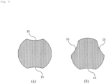
- Fig. 3 shows examples of a variation of one portion 12a of the outer edge of a cross section perpendicular to the long axis direction of the outer cover 12.
- Fig. 3(a) shows an example in which the concave portion is a linear notch provided for the outer edge of the outer cover 12.
- Fig. 3(b) shows an example in which the concave portion is a rectangular notch provided for the outer edge of the outer cover 12.
- Fig. 3(c) shows an example in which the concave portion is an L-shaped notch provided for the outer edge of the outer cover 12.
- Fig. 3(d) shows an example including two convex portions 5a and 5b for the outer edge of the outer cover 12.
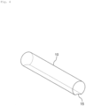
- Fig. 4 and Fig. 5 show the entire image of the optical fiber cable 10 according to the present embodiment.
- a surface for impression marking 15 may be formed on the entire optical fiber cable 10 from end to end as shown in Fig. 4 , or may be formed on only a part of the optical fiber cable 10 as shown in Fig. 5 .
- the surface for impression marking 15 may be formed only on a part of the optical fiber cable 10, it may be formed at a constant interval in the long axis direction.
- a plurality of surfaces for impression marking 15 may be provided on the outer edge of the outer cover 12, and these plurality of surfaces for impression marking 15 may be formed at constant intervals on the outer edge.
- the surface for impression marking 15 is constituted by one portion 12a of an outer edge whose center is a concave portion is described in Figs. 4 , 5 and 6 , the embodiment is not limited thereto.
- the impression 13 is marked between the two points 14a and 14b on the surface of the outer cover 12, that is, on the surface for impression marking 15.
- the arrangement of the impression 13 can be any arrangement as long as the impression is marked inside the surface for impression marking 15.
- the impression 13 may be marked inside the surface for impression marking 15 at a constant interval in the long axis direction or continuously in the long axis direction.
- Fig. 7 shows a second embodiment of the present disclosure.
- Fig. 7(a) shows a side surface of an optical fiber cable manufacturing apparatus 20, and
- Fig. 7(b) shows a cross section taken along a line A-A in Fig. 7(a) .
- the optical fiber cable manufacturing apparatus 20 is an apparatus for manufacturing an optical fiber cable according to the first embodiment, and includes an outer cover forming unit 22 and an impression marking unit 23.
- the outer cover forming unit 22 covers the cable core 11 with the outer cover 12, and produces the surface for impression marking 15 described in the first embodiment on the surface of the outer cover 12.
- the impression marking unit 23 marks an impression 13 on the surface for impression marking 15 of the outer cover 12.
- the optical fiber cable manufacturing apparatus 20 may include a plurality of impression marking units 23.
- optical fiber cable 10 having the structure described in the first embodiment can be manufactured by the optical fiber cable manufacturing apparatus 20 having the structure described above.
- Fig. 8 shows a third embodiment of the present invention.
- Fig. 8 is a diagram for explaining a method for laying the optical fiber cable 10 in the conduit or the like 30.
- the conduit or the like 30 and the optical fiber cable 10 are the same as those in the first embodiment.
- An method for laying an optical fiber cable includes a selecting step and a laying step.
- the optical fiber cable 10 is selected from a plurality of optical fiber cables 10 having different kinds of concave portions or convex portions as shown in Figs. 1 to 3 and 6 in accordance with the radius of curvature of the conduit or the like 30 for laying the optical fiber cable 10.
- the optical fiber cable 10 in which the center of one portion 12a of the outer edge of the outer cover 12 is convex as shown in Fig. 2 may be selected.
- the thickness of the outer cover 12 can be secured further than that of the optical fiber cable 10 in which the center of one portion 12a of the outer edge is concave, the impression 13 can be prevented from wearing off and the cable core 11 can be protected further.
- the optical fiber cable 10 as shown in Fig. 3(b) or Fig. 3(d) may be selected.
- the optical fiber cable 10 as shown in Fig. 6 may be used.
- the method for laying the optical fiber cable according to the present embodiment performs the laying step after performing the selecting step.
- the laying step as shown in Fig. 8 , the optical fiber cable 10 selected in the selecting step is laid in the conduit or the like 30.
- the impression 13 is less likely to come into contact with the inner wall of the conduit or the like 30. Therefore, the impression 13 can be prevented from wearing off.
- An optical fiber cable, an optical fiber cable manufacturing apparatus, a method for manufacturing an optical fiber cable, and a method for laying an optical fiber cable according to the present disclosure can be applied to an information communication industry.
Landscapes
- Physics & Mathematics (AREA)
- General Physics & Mathematics (AREA)
- Optics & Photonics (AREA)
- Engineering & Computer Science (AREA)
- Manufacturing & Machinery (AREA)
- Light Guides In General And Applications Therefor (AREA)
- Optical Fibers, Optical Fiber Cores, And Optical Fiber Bundles (AREA)
Abstract
Description
- The present disclosure relates to an optical fiber cable, an optical fiber cable manufacturing apparatus, an optical fiber cable manufacturing method, and an optical fiber cable laying method.
- In recent years, in order to cope with increases in traffic demand of communication, increases in capacity of optical fiber transmission systems have progressed (see, for example, NPL 1). In a large-capacity optical transmission system, an allowable signal-to-noise ratio is becoming smaller. Therefore, it is necessary to further reduce the loss of the optical transmission line so that the signal-to-noise ratio can be secured.
- Losses of an optical fiber transmission line include a loss generated in an optical fiber cable and a loss generated at a point connecting optical fiber cables. In particular, the latter loss can be expected to be reduced by reducing the number of connecting points on the transmission lines. Reducing the number of connecting points means laying long optical fiber cables. In recent years, an optical fiber cable which realizes a small diameter and a light weight by abolishing a slot rod for housing and protecting an optical fiber has been developed and put into practical use (see, for example, PTL 1). Further, there is a likelihood that a longer optical fiber cable can be laid.
- In an optical fiber cable, an impression is marked on a surface of an outer cover to enable a constructor to know the type and the length of the cable that the constructor lays. Since the impression is in contact with an inner wall of a conduit or the like in laying the cable, it is necessary to mark the impression by a method strong enough to keep the impression from wearing off.
- [PTL 1]
Japanese Patent No. 4774337 (NTT - [NPL 1] J. Yu and X. Zhou, "Ultra-High-Capacity DWDM transmission systems for 100G and beyond," in IEEE Communications Magazine, vol. 48, No. 3, PP. S56-S64, March 2010, doi: 10.1109/MCOM. 2010.5434379.
- Nevertheless, however resistant to abrasion the employed marking method is, there is a likelihood of the impression wearing off where a long optical fiber cable is laid. Therefore, it has been challenging to realize an optical fiber cable, however long the optical fiber cable is, having no fear of the impression wearing off.
- In order to solve the above problem, an object of the present disclosure is to prevent an impression, marked on a side surface of an outer cover of an optical fiber cable, from wearing off caused by laying.
- In order to achieve the above object, in an optical fiber cable of the present disclosure, a concave portion or a plurality of convex portions are provided on an outer edge of a cross section perpendicular to a long axis direction of an outer cover, and an impression is marked on the concave portion or on a portion sandwiched between the plurality of convex portions of the side surface of the outer cover.
- Specifically, an optical fiber cable according to the present disclosure includes
- a cable core having one or a plurality of optical fiber core wires therein;
- an outer cover which covers the cable core and has a concave portion or a plurality of convex portions for an outer edge of a cross section perpendicular to a long axis direction of the outer cover; and
- an impression which is marked on the concave portion or on a portion sandwiched between the plurality of convex portions on a side surface of the outer cover.
- Specifically, an optical fiber cable manufacturing apparatus according to the present disclosure includes
- an outer cover forming unit which covers a cable core, having one or a plurality of optical fiber core wires therein, with an outer cover, and forms a concave portion or a plurality of convex portions for an outer edge of a cross section perpendicular to a long axis direction of the outer cover, for at least a part of the outer cover; and
- an impression marking unit which marks an impression on the concave portion or on a portion sandwiched between the plurality of convex portions of a side surface of the outer cover.
- Specifically, the present disclosure provides a method for manufacturing an optical fiber cable, the method including: covering a cable core, having one or a plurality of optical fiber core wires therein, with an outer cover;
- forming a concave portion or a plurality of convex portions for an outer edge of a cross section perpendicular to a long axis direction of the outer cover, for at least a part of the outer cover; and
- marking an impression on the concave portion or on a portion sandwiched between the plurality of convex portions of a side surface of the outer cover.
- Specifically, the present disclosure provides a method for laying an optical fiber cable, the method including:
selecting the optical fiber cable from a plurality of optical fiber cables, having different concave portions or a plurality of convex portions, for an outer edge of a cross section perpendicular to a long axis direction of at least a part of an outer cover, in accordance with a radius of curvature of an inner diameter of a cross section perpendicular to a long axis direction of a conduit for laying the optical fiber cable; and laying the selected optical fiber cable on an inner wall of the conduit. - According to the present disclosure, it is practicable to prevent an impression, marked on the side surface of the outer cover of the optical fiber cable, from wearing off caused by laying.
-
- [
Fig. 1] Fig. 1 shows an example of a structure of an optical fiber cable according to a first embodiment. - [
Fig. 2] Fig. 2 shows an example of a structure of an optical fiber cable according to a first embodiment. - [
Fig. 3] Fig. 3 shows examples of a structure of an optical fiber cable according to a first embodiment. - [
Fig. 4] Fig. 4 shows an example of a structure of an optical fiber cable according to a first embodiment. - [
Fig. 5] Fig. 5 shows an example of a structure of an optical fiber cable according to a first embodiment. - [
Fig. 6] Fig. 6 shows an example of a structure of an optical fiber cable according to a first embodiment. - [
Fig. 7] Fig. 7 shows an example of a configuration of an optical fiber cable manufacturing apparatus according to a second embodiment. - [
Fig. 8] Fig. 8 shows an example of an optical fiber cable laying method according to a third embodiment. - Embodiments of the present disclosure will be described hereinafter in detail with reference to the drawings. It is to be understood that the present disclosure is not limited to the embodiments described below. The embodiments are merely exemplary and the present disclosure can be implemented in various modified and improved modes based on knowledge of those skilled in the art. Constituent elements with the same reference signs in the present specification and in the drawings represent the same constituent elements.
-
Fig. 1 shows a first embodiment of the present invention.Fig. 1 shows a cross section perpendicular to a long axis direction of anoptical fiber cable 10. - The
optical fiber cable 10 includes acable core 11 formed by assembling one or a plurality of coated optical fibers (not shown) therein, and anouter cover 12 that covers thecable core 11. - An outer edge in the cross section perpendicular to the long axis direction of the
outer cover 12 may have at least one set of twopoints points shortest curve 31 having a predetermined radius of curvature ρ and thecurve 31 is connected to be convex toward the outside of theouter cover 12, thecurve 31 is located outside theouter cover 12. That is, the condition is that twopoints outer cover 12 is in contact with the inside of the curve of the radius of curvature ρ. - Here, the radius of curvature ρ may be the radius of curvature of the inner diameter of the cross section perpendicular to the long axis direction of a conduit or the like 30 in which the
optical fiber cable 10 is laid. In this regard, since the minimum radius of curvature at which theoptical fiber cable 10 can be laid in the conduit or the like 30 is the radius of theoptical fiber cable 10, a lower limit of the radius of curvature ρ is the radius of theoptical fiber cable 10. - The two
points Fig. 1 can be realized by providing a concave portion or a plurality of convex portions for an outer edge of a cross section perpendicular to the long axis direction of theouter cover 12. Hereinafter, the concave portion is a portion located inside an outer peripheral circle, around theouter cover 12, having theother portion 12b of the outer edge of theouter cover 12 as a circumference, and the twopoints outer cover 12, having theother portion 12b of the outer edge of theouter cover 12 as a circumference. When theoptical fiber cable 10 includes the plurality of convex portions, at least two of the plurality of convex portions are in contact with the inside of the curve of the radius of curvature ρ.Fig. 1 shows an example in which the concave portion is formed for the outer edge of a cross section perpendicular to the long axis direction of theouter cover 12. A region sandwiched between the twopoints outer cover 12 functions as a surface for impression marking on which theimpression 13 is marked. -
Fig. 2 shows another example in which oneportion 12a of the outer edge of a cross section perpendicular to the long axis direction of theouter cover 12 is a concave portion. Theoptical fiber cable 10 and the conduit or the like 30 shown inFig. 2 are the same as those shown inFig. 1 , and the shape of theouter cover 12 is different from that shown inFig. 1 . - The center of one
portion 12a of the outer edge shown inFig. 2 is an outward convex curve, and the radius of curvature of the center of oneportion 12a of the outer edge is larger than that of theother portion 12b of the outer edge. Further, it is desirable that the radius of curvature of the center of oneportion 12a of the outer edge be larger than the radius of curvature ρ. - When the radius of curvature is not defined as one value, the radius of curvature may be defined as a maximum radius of curvature, which is representative therefor. For example, when the conduit or the like 30 has a radius of curvature defined as a plurality of values, the maximum radius of curvature of them is regarded as the radius of curvature ρ, and the radius of curvature of the convex shape at the center of one
portion 12a of the outer edge shown inFig. 2 is set to be larger than the radius of curvature ρ. - When the
optical fiber cable 10 is laid on a plane such as a road face instead of in a conduit, the condition imposed on theouter cover 12 is that the twopoints outer cover 12 is in contact with a straight line. In this situation, it is desirable that the center of oneportion 12a of the outer edge be a concave portion as shown inFig. 1 . -
Fig. 3 shows examples of a variation of oneportion 12a of the outer edge of a cross section perpendicular to the long axis direction of theouter cover 12. -
Fig. 3(a) shows an example in which the concave portion is a linear notch provided for the outer edge of theouter cover 12. -
Fig. 3(b) shows an example in which the concave portion is a rectangular notch provided for the outer edge of theouter cover 12. -
Fig. 3(c) shows an example in which the concave portion is an L-shaped notch provided for the outer edge of theouter cover 12. -
Fig. 3(d) shows an example including twoconvex portions outer cover 12. -
Fig. 4 andFig. 5 show the entire image of theoptical fiber cable 10 according to the present embodiment. - A surface for impression marking 15 may be formed on the entire
optical fiber cable 10 from end to end as shown inFig. 4 , or may be formed on only a part of theoptical fiber cable 10 as shown inFig. 5 . When the surface for impression marking 15 is formed only on a part of theoptical fiber cable 10, it may be formed at a constant interval in the long axis direction. - Further, as shown in
Fig. 6 , a plurality of surfaces for impression marking 15 may be provided on the outer edge of theouter cover 12, and these plurality of surfaces for impression marking 15 may be formed at constant intervals on the outer edge. Although an example in which the surface for impression marking 15 is constituted by oneportion 12a of an outer edge whose center is a concave portion is described inFigs. 4 ,5 and6 , the embodiment is not limited thereto. - The
impression 13 is marked between the twopoints outer cover 12, that is, on the surface for impression marking 15. The arrangement of theimpression 13 can be any arrangement as long as the impression is marked inside the surface for impression marking 15. For example, theimpression 13 may be marked inside the surface for impression marking 15 at a constant interval in the long axis direction or continuously in the long axis direction. - Using such a structure, in laying the
optical fiber cable 10 in the conduit or the like 30, the likelihood of theimpression 13 coming into contact with the inner wall of the conduit or the like 30 is reduced. Therefore, theimpression 13 can be prevented from wearing off. -
Fig. 7 shows a second embodiment of the present disclosure.Fig. 7(a) shows a side surface of an optical fiber cable manufacturing apparatus 20, andFig. 7(b) shows a cross section taken along a line A-A inFig. 7(a) . - The optical fiber cable manufacturing apparatus 20 according to the present embodiment is an apparatus for manufacturing an optical fiber cable according to the first embodiment, and includes an outer
cover forming unit 22 and animpression marking unit 23. - The outer
cover forming unit 22 covers thecable core 11 with theouter cover 12, and produces the surface for impression marking 15 described in the first embodiment on the surface of theouter cover 12. - The
impression marking unit 23 marks animpression 13 on the surface for impression marking 15 of theouter cover 12. As shown inFig. 6 , when a plurality of surfaces for impression marking 15 are formed on the outer edge of the cross section perpendicular to the long axis direction of theouter cover 12, the optical fiber cable manufacturing apparatus 20 may include a plurality ofimpression marking units 23. - The
optical fiber cable 10 having the structure described in the first embodiment can be manufactured by the optical fiber cable manufacturing apparatus 20 having the structure described above. -
Fig. 8 shows a third embodiment of the present invention.Fig. 8 is a diagram for explaining a method for laying theoptical fiber cable 10 in the conduit or the like 30. The conduit or the like 30 and theoptical fiber cable 10 are the same as those in the first embodiment. - An method for laying an optical fiber cable according to the present embodiment includes a selecting step and a laying step. In the selecting step, the
optical fiber cable 10 is selected from a plurality ofoptical fiber cables 10 having different kinds of concave portions or convex portions as shown inFigs. 1 to 3 and6 in accordance with the radius of curvature of the conduit or the like 30 for laying theoptical fiber cable 10. For example, when the radius of curvature of the conduit or the like 30 is low, theoptical fiber cable 10 in which the center of oneportion 12a of the outer edge of theouter cover 12 is convex as shown inFig. 2 may be selected. In this example, since the thickness of theouter cover 12 can be secured further than that of theoptical fiber cable 10 in which the center of oneportion 12a of the outer edge is concave, theimpression 13 can be prevented from wearing off and thecable core 11 can be protected further. In addition, for example, when it is desired to secure the distance between the surface for impression marking 15 and the inner wall of the conduit or the like 30, theoptical fiber cable 10 as shown inFig. 3(b) or Fig. 3(d) may be selected. When a plurality of abrasions occur on the side surface of theoptical fiber cable 10, theoptical fiber cable 10 as shown inFig. 6 may be used. - The method for laying the optical fiber cable according to the present embodiment performs the laying step after performing the selecting step. In the laying step, as shown in
Fig. 8 , theoptical fiber cable 10 selected in the selecting step is laid in the conduit or the like 30. - As described above, by virtue of the method for laying the optical fiber cable according to the present embodiment, even though the
optical fiber cable 10 is laid in the conduit or the like 30, theimpression 13 is less likely to come into contact with the inner wall of the conduit or the like 30. Therefore, theimpression 13 can be prevented from wearing off. - An optical fiber cable, an optical fiber cable manufacturing apparatus, a method for manufacturing an optical fiber cable, and a method for laying an optical fiber cable according to the present disclosure can be applied to an information communication industry.
-
- 5:
- Convex portion
- 10:
- Optical fiber cable
- 11:
- Cable core
- 12:
- Outer cover
- 13:
- Impression
- 14:
- Point
- 15:
- Surface for impression marking
- 20:
- Optical fiber cable manufacturing apparatus
- 22:
- Outer cover forming unit
- 23:
- Impression marking unit
- 30:
- Conduit or the like
- 31:
- Curve
Claims (6)
- An optical fiber cable comprising:a cable core having one or a plurality of optical fiber core wires therein;an outer cover which covers the cable core and has a concave portion or a plurality of convex portions for an outer edge of a cross section perpendicular to a long axis direction of the outer cover; andan impression which is marked on the concave portion or on a portion sandwiched between the plurality of convex portions of a side surface of the outer cover.
- The optical fiber cable according to claim 1,
wherein both ends of the concave portion are or the plurality of convex portions are in contact with the inside of a curve of a predetermined radius of curvature. - The optical fiber cable according to claim 2,
wherein the predetermined radius of curvature is a radius of curvature of an inner diameter of a cross section perpendicular to a long axis direction of a conduit in which the optical fiber cable is laid. - An optical fiber cable manufacturing apparatus comprising:an outer cover forming unit which covers a cable core, having one or a plurality of optical fiber core wires therein, with an outer cover, and forms a concave portion or a plurality of convex portions for an outer edge of a cross section perpendicular to a long axis direction of the outer cover, for at least a part of the outer cover; andan impression marking unit which marks an impression on the concave portion or on a portion sandwiched between the plurality of convex portions of a side surface of the outer cover.
- A method for manufacturing an optical fiber cable, the method comprising:covering a cable core, having one or a plurality of optical fiber core wires therein, with an outer cover;forming a concave portion or a plurality of convex portions for an outer edge of a cross section perpendicular to a long axis direction of the outer cover, for at least a part of the outer cover; andmarking an impression on the concave portion or on a portion sandwiched between the plurality of convex portions of a side surface of the outer cover.
- A method for laying an optical fiber cable, the method comprising:
selecting an optical fiber cable from a plurality of optical fiber cables, having different concave portions or a plurality of convex portions, for an outer edge of a cross section perpendicular to a long axis direction of at least a part of an outer cover, in accordance with a radius of curvature of an inner diameter of a cross section perpendicular to a long axis direction of a conduit for laying the optical fiber cable; and laying the selected optical fiber cable on an inner wall of the conduit.
Applications Claiming Priority (1)
| Application Number | Priority Date | Filing Date | Title |
|---|---|---|---|
| PCT/JP2021/020752 WO2022254555A1 (en) | 2021-05-31 | 2021-05-31 | Optical fiber cable, optical fiber cable manufacturing device, optical fiber cable manufacturing method, and optical fiber cable laying method |
Publications (2)
| Publication Number | Publication Date |
|---|---|
| EP4350407A1 true EP4350407A1 (en) | 2024-04-10 |
| EP4350407A4 EP4350407A4 (en) | 2025-04-02 |
Family
ID=84323994
Family Applications (1)
| Application Number | Title | Priority Date | Filing Date |
|---|---|---|---|
| EP21944063.3A Pending EP4350407A4 (en) | 2021-05-31 | 2021-05-31 | Optical fiber cable, device for producing an optical fiber cable, method for producing an optical fiber cable and method for laying an optical fiber cable |
Country Status (5)
| Country | Link |
|---|---|
| US (1) | US20240302620A1 (en) |
| EP (1) | EP4350407A4 (en) |
| JP (1) | JPWO2022254555A1 (en) |
| CN (1) | CN117355779A (en) |
| WO (1) | WO2022254555A1 (en) |
Family Cites Families (6)
| Publication number | Priority date | Publication date | Assignee | Title |
|---|---|---|---|---|
| FR2793565B1 (en) * | 1999-05-12 | 2002-05-24 | Sagem | OPTICAL FIBER CABLE HAVING LONGITUDINAL REINFORCEMENTS |
| JP2009086177A (en) * | 2007-09-28 | 2009-04-23 | Sumitomo Electric Ind Ltd | Optical cable unit, collective optical cable, and optical cable unit detection method |
| JP2011023274A (en) * | 2009-07-17 | 2011-02-03 | Sumitomo Electric Ind Ltd | Communication cable |
| US8942526B2 (en) * | 2011-11-10 | 2015-01-27 | Commscope, Inc. Of North Carolina | Miniaturized optical fiber drop cable |
| US9297975B2 (en) * | 2013-07-19 | 2016-03-29 | Corning Optical Communications LLC | Optical fiber cable with print protective outer surface profile |
| JP7207215B2 (en) * | 2019-07-22 | 2023-01-18 | 住友電気工業株式会社 | fiber optic cable |
-
2021
- 2021-05-31 WO PCT/JP2021/020752 patent/WO2022254555A1/en not_active Ceased
- 2021-05-31 EP EP21944063.3A patent/EP4350407A4/en active Pending
- 2021-05-31 US US18/289,247 patent/US20240302620A1/en active Pending
- 2021-05-31 CN CN202180098400.9A patent/CN117355779A/en active Pending
- 2021-05-31 JP JP2023525196A patent/JPWO2022254555A1/ja active Pending
Also Published As
| Publication number | Publication date |
|---|---|
| EP4350407A4 (en) | 2025-04-02 |
| CN117355779A (en) | 2024-01-05 |
| JPWO2022254555A1 (en) | 2022-12-08 |
| US20240302620A1 (en) | 2024-09-12 |
| WO2022254555A1 (en) | 2022-12-08 |
Similar Documents
| Publication | Publication Date | Title |
|---|---|---|
| JP5440183B2 (en) | Optical fiber and optical cable | |
| EP3132297B1 (en) | Optical fiber connector assembly | |
| US4226504A (en) | Protection of optical fibers | |
| US20060133748A1 (en) | Fiber optic drop cables suitable for fiber to the subscriber applications | |
| WO2017138572A1 (en) | Optical fiber cable | |
| US9739966B2 (en) | Fiber optic cable with electrical conductors | |
| CN102472877A (en) | Connector-equipped assembled optical cable | |
| US20190041599A1 (en) | Gimbal Transmission Cable Management | |
| JP6554875B2 (en) | Fiber optic cable | |
| US11360264B2 (en) | Telecommunications splice arrangements | |
| JP2016148709A (en) | Optical fiber unit and optical cable | |
| US20240302620A1 (en) | Optical fiber cable, optical fiber cable manufacturing equipment, optical fiber cable manufacturing method and optical fiber cable laying method | |
| US12613387B2 (en) | Optical fiber cable | |
| EP4227720A1 (en) | Optical cable | |
| KR20110012705A (en) | Centralized loose tube double sheathed fiber optic cable | |
| EP3663825B1 (en) | Flat drop optical fiber cable | |
| JP2011059607A (en) | Optical wiring method and optical wiring system | |
| JPS6113208A (en) | Optical cable | |
| EP4350408A1 (en) | Fiber-optic cable and fiber-optic cable manufacturing device | |
| KR20140051538A (en) | Tight buffered optical fiber and distribution/break-out cable using the same | |
| US12601884B2 (en) | Optical fiber cable with tensile material between the inner reinforcing projection | |
| KR102780867B1 (en) | Optic jumper cable | |
| EP0825465A1 (en) | Optical fiber element for single core power cable | |
| CN107250865A (en) | Hybrid fiber band and power cable | |
| JPH08292348A (en) | Fiber optic cable |
Legal Events
| Date | Code | Title | Description |
|---|---|---|---|
| STAA | Information on the status of an ep patent application or granted ep patent |
Free format text: STATUS: THE INTERNATIONAL PUBLICATION HAS BEEN MADE |
|
| PUAI | Public reference made under article 153(3) epc to a published international application that has entered the european phase |
Free format text: ORIGINAL CODE: 0009012 |
|
| STAA | Information on the status of an ep patent application or granted ep patent |
Free format text: STATUS: REQUEST FOR EXAMINATION WAS MADE |
|
| 17P | Request for examination filed |
Effective date: 20231027 |
|
| AK | Designated contracting states |
Kind code of ref document: A1 Designated state(s): AL AT BE BG CH CY CZ DE DK EE ES FI FR GB GR HR HU IE IS IT LI LT LU LV MC MK MT NL NO PL PT RO RS SE SI SK SM TR |
|
| DAV | Request for validation of the european patent (deleted) | ||
| DAX | Request for extension of the european patent (deleted) | ||
| A4 | Supplementary search report drawn up and despatched |
Effective date: 20250305 |
|
| RIC1 | Information provided on ipc code assigned before grant |
Ipc: G02B 6/46 20060101ALI20250227BHEP Ipc: G02B 6/44 20060101AFI20250227BHEP |
|
| RAP3 | Party data changed (applicant data changed or rights of an application transferred) |
Owner name: NTT, INC. |
|
| STAA | Information on the status of an ep patent application or granted ep patent |
Free format text: STATUS: EXAMINATION IS IN PROGRESS |
|
| 17Q | First examination report despatched |
Effective date: 20251029 |