EP4350263A1 - Washing/drying apparatus and washing/drying method - Google Patents
Washing/drying apparatus and washing/drying method Download PDFInfo
- Publication number
- EP4350263A1 EP4350263A1 EP22837680.2A EP22837680A EP4350263A1 EP 4350263 A1 EP4350263 A1 EP 4350263A1 EP 22837680 A EP22837680 A EP 22837680A EP 4350263 A1 EP4350263 A1 EP 4350263A1
- Authority
- EP
- European Patent Office
- Prior art keywords
- washing
- washing liquid
- treatment target
- drying apparatus
- container
- Prior art date
- Legal status (The legal status is an assumption and is not a legal conclusion. Google has not performed a legal analysis and makes no representation as to the accuracy of the status listed.)
- Pending
Links
Images





Classifications
-
- F—MECHANICAL ENGINEERING; LIGHTING; HEATING; WEAPONS; BLASTING
- F26—DRYING
- F26B—DRYING SOLID MATERIALS OR OBJECTS BY REMOVING LIQUID THEREFROM
- F26B11/00—Machines or apparatus for drying solid materials or objects with movement which is non-progressive
- F26B11/12—Machines or apparatus for drying solid materials or objects with movement which is non-progressive in stationary drums or other mainly-closed receptacles with moving stirring devices
- F26B11/14—Machines or apparatus for drying solid materials or objects with movement which is non-progressive in stationary drums or other mainly-closed receptacles with moving stirring devices the stirring device moving in a horizontal or slightly-inclined plane
-
- F—MECHANICAL ENGINEERING; LIGHTING; HEATING; WEAPONS; BLASTING
- F26—DRYING
- F26B—DRYING SOLID MATERIALS OR OBJECTS BY REMOVING LIQUID THEREFROM
- F26B25/00—Details of general application not covered by group F26B21/00 or F26B23/00
- F26B25/001—Handling, e.g. loading or unloading arrangements
- F26B25/002—Handling, e.g. loading or unloading arrangements for bulk goods
-
- F—MECHANICAL ENGINEERING; LIGHTING; HEATING; WEAPONS; BLASTING
- F26—DRYING
- F26B—DRYING SOLID MATERIALS OR OBJECTS BY REMOVING LIQUID THEREFROM
- F26B25/00—Details of general application not covered by group F26B21/00 or F26B23/00
- F26B25/04—Agitating, stirring, or scraping devices
-
- F—MECHANICAL ENGINEERING; LIGHTING; HEATING; WEAPONS; BLASTING
- F26—DRYING
- F26B—DRYING SOLID MATERIALS OR OBJECTS BY REMOVING LIQUID THEREFROM
- F26B3/00—Drying solid materials or objects by processes involving the application of heat
- F26B3/18—Drying solid materials or objects by processes involving the application of heat by conduction, i.e. the heat is conveyed from the heat source, e.g. gas flame, to the materials or objects to be dried by direct contact
- F26B3/22—Drying solid materials or objects by processes involving the application of heat by conduction, i.e. the heat is conveyed from the heat source, e.g. gas flame, to the materials or objects to be dried by direct contact the heat source and the materials or objects to be dried being in relative motion, e.g. of vibration
- F26B3/24—Drying solid materials or objects by processes involving the application of heat by conduction, i.e. the heat is conveyed from the heat source, e.g. gas flame, to the materials or objects to be dried by direct contact the heat source and the materials or objects to be dried being in relative motion, e.g. of vibration the movement being rotation
-
- F—MECHANICAL ENGINEERING; LIGHTING; HEATING; WEAPONS; BLASTING
- F26—DRYING
- F26B—DRYING SOLID MATERIALS OR OBJECTS BY REMOVING LIQUID THEREFROM
- F26B2200/00—Drying processes and machines for solid materials characterised by the specific requirements of the drying goods
- F26B2200/04—Garbage
-
- F—MECHANICAL ENGINEERING; LIGHTING; HEATING; WEAPONS; BLASTING
- F26—DRYING
- F26B—DRYING SOLID MATERIALS OR OBJECTS BY REMOVING LIQUID THEREFROM
- F26B2200/00—Drying processes and machines for solid materials characterised by the specific requirements of the drying goods
- F26B2200/08—Granular materials
-
- Y—GENERAL TAGGING OF NEW TECHNOLOGICAL DEVELOPMENTS; GENERAL TAGGING OF CROSS-SECTIONAL TECHNOLOGIES SPANNING OVER SEVERAL SECTIONS OF THE IPC; TECHNICAL SUBJECTS COVERED BY FORMER USPC CROSS-REFERENCE ART COLLECTIONS [XRACs] AND DIGESTS
- Y02—TECHNOLOGIES OR APPLICATIONS FOR MITIGATION OR ADAPTATION AGAINST CLIMATE CHANGE
- Y02W—CLIMATE CHANGE MITIGATION TECHNOLOGIES RELATED TO WASTEWATER TREATMENT OR WASTE MANAGEMENT
- Y02W30/00—Technologies for solid waste management
- Y02W30/50—Reuse, recycling or recovery technologies
- Y02W30/62—Plastics recycling; Rubber recycling
Definitions
- the present disclosure relates to a washing and drying apparatus for washing and drying a treatment target which is powder and made of a polymeric organic compound and a method for washing and drying the treatment target which is powder and made of the polymeric organic compound.
- a washing apparatus and a drying apparatus have conventionally been used separately for washing and drying a treatment target made of a polymerizable organic compound.
- the washing apparatus has a container main body and a stirring blade, holds a treatment target and water in the container main body, and washes the treatment target with water by rotation of the stirring blade.
- the drying apparatus has a rotatable container main body, holds the treatment target after being washed in the container main body, and dries the treatment target while rotating the container main body ( JP 61-130893 U1 : see Patent Literature 1).
- Patent Literature 1 JP 61-130893 U1
- an object of the present disclosure is to provide a washing and drying apparatus and a washing and drying method that can save space for placing the apparatus and reduce a workload.
- a washing and drying apparatus which is a first aspect of the present disclosure is an apparatus capable of washing a treatment target which is powder and made of a polymeric organic compound (e.g., consist of a polymeric organic compound) with a washing liquid and drying the treatment target.
- the washing and drying apparatus includes a container, a stirring blade arranged inside the container and capable of rotating, a filter arranged in the container and capable of separately filtering the treatment target and the washing liquid, a heater arranged in the container and capable of heating an inside of the container, and a control device that rotates the stirring blade at a time of washing and a time of drying the treatment target and actuates the heater at the time of drying.
- the container has a container main body, a treatment target supply tube communicating with the inside of the container main body and capable of supplying the treatment target, a washing liquid supply tube communicating with the inside of the container main body and capable of supplying the washing liquid, a treatment target discharge tube communicating with the inside of the container main body and capable of discharging the treatment target, and a washing liquid discharge tube communicating with the inside of the container main body and capable of discharging the washing liquid.
- the filter is provided for the container main body and located at an upstream side of the washing liquid discharge tube.
- a second aspect is the washing and drying apparatus of the first aspect, in which the filter is capable of separately filtering the washing liquid and the treatment target of more than or equal to 50 pm.
- a third aspect is the washing and drying apparatus of the first or second aspect, in which the stirring blade has a shaft and a fin wound around the shaft so as to form a continuous helix along the shaft.
- a fourth aspect is the washing and drying apparatus of the first or second aspect, in which the stirring blade has a shaft and a plurality of fins wound around the shaft so as to form a discontinuous helix along the shaft.
- a fifth aspect is the washing and drying apparatus of any one of the first to fourth aspects, in which the stirring blade is capable of revolving while rotating.
- a sixth aspect is the washing and drying apparatus of any one of the first to fifth aspects, further including a decompression device capable of decompressing the inside of the container.
- a seventh aspect is the washing and drying apparatus of any one of the first to sixth aspects, in which the container is capable of retaining the washing liquid at the time of washing.
- an eighth aspect is the washing and drying apparatus of any one of the first to sixth aspects, in which the container has a spray nozzle communicating with the washing liquid supply tube and capable of spraying the washing liquid.
- a ninth aspect is the washing and drying apparatus of any one of the first to eighth aspects, in which the treatment target is made of resin.
- a tenth aspect is the washing and drying apparatus of any one of the first to eighth aspects, in which the treatment target is made of fluororesin.
- an eleventh aspect is the washing and drying apparatus of any one of the first to tenth aspects, in which the treatment target has an average particle size of more than or equal to 20 pm.
- a twelfth aspect is the washing and drying apparatus of any one of the first to eleventh aspects, in which the container main body has a cylindrical sidewall part, a top part attached to a first opening of the sidewall part, and a bottom part attached to a second opening of the sidewall part, the bottom part has a treatment target discharge hole communicating with the treatment target discharge tube and a washing liquid discharge hole communicating with the washing liquid discharge tube, and the filter is provided at the washing liquid discharge hole.
- a thirteenth aspect is the washing and drying apparatus of the twelfth aspect, in which the filter is arranged in a region closer to an outer circumference of the bottom part.
- a fourteenth aspect is the washing and drying apparatus of the thirteenth aspect, in which part of the heater is arranged in a region closer to a center of the bottom part.
- a fifteenth aspect is the washing and drying apparatus of any one of the twelfth to fourteenth aspects, in which an inner surface of the bottom part at an inner side of the container main body is flat, and the filter is provided on the inner surface.
- a sixteenth aspect is the washing and drying apparatus of any one of the twelfth to fifteenth aspects, in which the treatment target discharge hole and the washing liquid discharge hole are arranged in a circumferential direction around a central axis of the container main body when viewed in a direction along the central axis.
- a seventeenth aspect is the washing and drying apparatus of the sixteenth aspect, in which the washing liquid discharge hole includes a plurality of washing liquid discharge holes, and the treatment target discharge hole and the washing liquid discharge holes are arranged so as to have an evenly-spaced central angle around the central axis.
- an eighteenth aspect is the washing and drying apparatus of the sixteenth or seventeenth aspect, in which the washing liquid discharge hole includes a plurality of washing liquid discharge holes, the top part has a treatment target supply hole communicating with the treatment target supply tube and a washing liquid supply hole communicating with the washing liquid supply tube, and an opening of the treatment target supply hole at the inner side of the container main body and an opening of the washing liquid supply hole at the inner side of the container main body are located between any washing liquid discharge holes adjacent to each other in the circumferential direction among the washing liquid discharge holes when viewed in the direction along the central axis.
- a nineteenth aspect is the washing and drying apparatus of any one of the sixteenth to eighteenth aspects, in which the washing liquid discharge hole includes a plurality of washing liquid discharge holes, and an inner circumferential trajectory of the fin of the stirring blade traced by rotation of the stirring blade crosses the treatment target discharge hole and the washing liquid discharge holes when viewed in the direction along the central axis.
- a method for washing and drying a treatment target being powdery and made of a polymeric organic compound of a twentieth aspect includes washing a treatment target which is powder and made of a polymeric organic compound with a washing liquid while rotating a stirring blade and discharging the washing liquid through a filter to separately filter the treatment target and the washing liquid, and actuating a heater while rotating the stirring blade to dry the treatment target.
- the washing and drying apparatus and the washing and drying method according to an aspect of the present disclosure can save space for placing the apparatus and reduce a workload.
- Figure 1 is a simplified configuration diagram showing a first embodiment of a washing and drying apparatus.
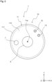
- Figure 2 is a top view of the washing and drying apparatus.
- Figure 3 is an XY sectional view of the washing and drying apparatus when viewed from above.
- the vertical direction (a height direction) when a washing and drying apparatus 1 is placed is referred to as a Z-direction
- the horizontal direction is referred to as an X-direction and a Y-direction
- the X-direction, the Y-direction, and the Z-direction are directions perpendicular to one another, and constitute the right-handed system when arrayed in the order to X, Y, and Z.
- the forward direction of the Z-direction is referred to as an upper direction
- the reverse direction of the Z-direction is referred to as a lower direction.
- the washing and drying apparatus 1 is an apparatus capable of washing a treatment target which is powder and made of a polymeric organic compound with a washing liquid and drying the treatment target.
- the washing and drying apparatus 1 includes a container 10, a stirring blade 20 arranged inside the container 10, a filter 30 arranged in the container 10, a heater 40 arranged in the container 10, and a control device 5 that controls the stirring blade 20 and the heater 40.
- the container 10 has a container main body 11, a treatment target supply tube 12 attached to the container main body 11, a washing liquid supply tube 13, a treatment target discharge tube 14, and a washing liquid discharge tube 15.
- the treatment target supply tube 12 communicates with the inside of the container main body 11 and is capable of supplying the treatment target.
- the washing liquid supply tube 13 communicates with the inside of the container main body 11 and is capable of supplying the washing liquid.
- the treatment target discharge tube 14 communicates with the inside of the container main body 11 and is capable of discharging the treatment target.
- the washing liquid discharge tube 15 communicates with the inside of the container main body 11 and is capable of discharging the washing liquid.
- the stirring blade 20 is capable of rotating by driving of a motor 6 attached to the container main body 11.
- the stirring blade 20 is capable of stirring the treatment target and the washing liquid at the time of washing the treatment target, and is capable of stirring the treatment target at the time of drying the treatment target.
- the filter 30 is provided for the container main body 11 and located at the upstream side of the washing liquid discharge tube 15.
- the filter 30 is capable of separately filtering the treatment target and the washing liquid.
- the heater 40 is capable of heating the inside of the container 10.
- the heater 40 is capable of heating the treatment target at the time of drying the treatment target.
- the control device 5 rotates the stirring blade 20 at the times of washing and drying the treatment target. Specifically describing, the control device 5 drives the motor 6 to rotate the stirring blade 20. The control device 5 also actuates the heater 40 at the time of drying the treatment target.
- the above-described configuration enables the treatment target to be supplied from the treatment target supply tube 12 into the container main body 11 and the washing liquid to be supplied from the washing liquid supply tube 13 into the container main body 11. Then, the treatment target can be washed with the washing liquid while the stirring blade 20 is being rotated.
- the washing liquid is discharged (at the time of dehydration)
- the treatment target and the washing liquid can be filtered separately by the filter 30.
- the treatment target can be discharged from the treatment target discharge tube 14, and the washing liquid can be discharged from the washing liquid discharge tube 15. Thereafter, the heater 40 can be actuated while the stirring blade 20 is being rotated to dry the treatment target.
- a washing step and a drying step can be performed with a single apparatus without the need to use a washing apparatus and a drying apparatus separately, which can save the space for placing the apparatus.
- the washing step and the drying step can be performed with a single apparatus, there is no need to move the treatment target from a washing apparatus to a drying apparatus, which can reduce a workload.
- the washing step requires water (the washing liquid) and the treatment target to be distributed as uniformly as possible, so that the revolutions per minute of the stirring blade need to be increased.
- the drying step only the treatment target is stirred with no water contained, which may increase resistance against the treatment target and may apply a load on the stirring blade. Thus, the revolutions per minute of the stirring blade need to be reduced. Consequently, it is difficult to perform the drying step with the conventionally-used washing apparatus.
- the inventor of the present application has found out that the treatment target can be washed by stirring both the treatment target and water without uniformly distributing the treatment target and water. That is, the inventor of the present application has found out that it is not necessary to increase the revolutions per minute of the stirring blade for uniform distribution and the treatment target can be washed even at lower revolutions per minute of the stirring blade.
- the treatment target is made of fluororesin, the treatment target has high water-repellency and the powdery treatment target and water are isolated completely in a stationary state, the inventor of the present application has found out that the treatment target can be washed by thus stirring both water and the powdery treatment target and bringing water and the powdery treatment target into contact only at the solid-liquid interface.
- the inventor of the present application has found out that the treatment target which is powder and made of a polymeric organic compound can be washed even at low revolutions per minute of the stirring blade at the time of drying, and has invented the washing and drying apparatus of the invention of the present application capable of performing the washing step and the drying step.
- the treatment target is made of resin, for example.
- the treatment target is readily isolated from water and can be washed even at lower revolutions per minute of the stirring blade 20. Consequently, a load on the stirring blade 20 at the time of washing can be reduced.
- the treatment target is preferably made of fluororesin. Since fluororesin has high water-repellency, the treatment target is more readily isolated from water and can be washed even at still lower revolutions per minute of the stirring blade 20. Consequently, a load on the stirring blade 20 at the time of washing can be reduced further.
- the treatment target has an average particle size of more than or equal to 20 ⁇ m, for example.
- the average particle size indicates a particle size at an integrated value of 50% in a particle size distribution obtained by the laser diffraction method.
- the washing liquid is water, for example.
- the washing liquid may be an organic solvent such as ethyl alcohol or methyl alcohol.
- the washing liquid contained in the treatment target after being dried has a water content of 0.2%, preferably less than or equal to 0.1%.
- the container main body 11 has a cylindrical sidewall part 111, a top part 112 attached to a first opening at the upper side of the sidewall part 111, and a bottom part 113 attached to a second opening at the lower side of the sidewall part 111.
- the sidewall part 111 has a cylindrical shape, for example.
- the top part 112 and the bottom part 113 have a disc shape, for example.
- a central axis 11a of the container main body 11 conforms to a central axis of the cylindrical sidewall part 111.
- a center of the top part 112 crosses the central axis 11a of the container main body 11.
- a center 113d of the bottom part 113 crosses the central axis 11a of the container main body 11.
- the top part 112 has a treatment target supply hole 112a communicating with the treatment target supply tube 12 and a washing liquid supply hole 112b communicating with the washing liquid supply tube 13.
- a treatment target supply hole 112a communicating with the treatment target supply tube 12
- a washing liquid supply hole 112b communicating with the washing liquid supply tube 13.
- One each of the treatment target supply hole 112a and the washing liquid supply hole 112b are provided.
- the bottom part 113 has a treatment target discharge hole 113a communicating with the treatment target discharge tube 14 and a washing liquid discharge hole 113b communicating with the washing liquid discharge tube 15.
- One treatment target discharge hole 113a and three washing liquid discharge holes 113b are provided.
- the treatment target supply tube 12 and the washing liquid supply tube 13 are attached to the top part 112. One each of the treatment target supply tube 12 and the washing liquid supply tube 13 are provided.
- the treatment target discharge tube 14 and the washing liquid discharge tube 15 are attached to the bottom part 113.
- One treatment target discharge tube 14 and three washing liquid discharge tubes 15 are provided.
- a first sluice valve 16 is attached to the treatment target discharge tube 14, and a second sluice valve 17 is attached to the washing liquid discharge tube 15.
- the container 10 is preferably provided with a decompression device 8 capable of decompressing the inside of the container 10.
- the decompression device 8 is connected to the container main body 11 via a bag filter 7 attached to the top part 112.
- the bag filter 7 can prevent the treatment target from being absorbed into the decompression device 8 when the decompression device 8 decompresses the inside of the container 10.
- the above-described configuration enables the inside of the container 10 to be decompressed by the decompression device 8 at the time of drying to dry the treatment target at low temperature.
- the container 10 is capable of retaining the washing liquid at the time of washing. Specifically describing, at the time of washing, the first and second sluice valves 16 and 17 are closed and the washing liquid is supplied from the washing liquid supply tube 13 into the container main body 11, so that the washing liquid can be retained in the container main body 11.
- the above-described configuration enables the washing liquid to be stored in the container 10 to wash the treatment target, which can reduce the quantity of the washing liquid as compared with a case of washing the treatment target while spraying the washing liquid.
- the stirring blade 20 has a shaft 21 and a fin 22 wound around the shaft 21 so as to form a continuous helix along the shaft 21.
- a plurality of supports 23 extending perpendicularly to a shaft center of the shaft 21 are attached to the shaft 21, and the fin 22 is supported by the supports 23.
- the stirring blade 20 is attached to the container main body 11 such that the shaft center of the shaft 21 conforms to the central axis 11a of the container main body 11.
- the stirring blade 20 rotates around the central axis 11a.
- the above-described configuration can increase the degree of stirring with the stirring blade 20 because the fin 22 forms a continuous helix.
- the stirring blade may be capable of revolving while rotating.
- the stirring blade may be attached to the container main body 11 such that the shaft center of the shaft is offset from the central axis 11a of the container main body 11, and the stirring blade may revolve around the central axis 11a while rotating around the shaft center of the shaft 21.
- the above-described configuration enables more reliable stirring with the stirring blade 20.
- the filters 30 are attached to openings of the washing liquid discharge holes 113b at the inner side of the container main body 11.
- the filters 30 are capable of separately filtering the washing liquid and the treatment target of more than or equal to 50 ⁇ m.
- the above-described configuration enables the washing liquid and the treatment target to be filtered separately.
- the filters 30 are composed of metal such as stainless steel or resin such as polyester or polyethylene, for example. Adjustment of a mesh size of the filters 30 enables treatment targets having various sizes to be filtered separately.
- the heater 40 is provided in the sidewall part 111 and the bottom part 112 of the container main body 11. Specifically describing, the heater 40 has a plurality of pipes 41, and the plurality of pipes 41 are buried in each of the sidewall part 111 and the bottom part 112. The inside of the container main body 11 can be heated by flowing a heating medium such as steam, oil, or warm water through the pipes 41.
- a heating medium such as steam, oil, or warm water
- the pipes 41 may be replaced by halved pipes, which can reduce cost.
- the pipes 41 may be replaced by an electric heater, which enables a more compact arrangement.
- the control device 5 rotates the stirring blade 20 at the time of washing the treatment target, and actuates the heater 40 while rotating the stirring blade 20 at the time of drying the treatment target.
- the control device 5 actuates the heater 40 at the time of washing the treatment target.
- the temperature rise at the time of washing can thus improve a washing effect.
- the control device 5 equalizes the revolutions per minute of the stirring blade 20 at the time of washing and the revolutions per minute of the stirring blade 20 at the time of drying.
- the revolutions per minute of the stirring blade 20 are 5 to 100 rpm, preferably 30 to 100 rpm.
- control device 5 may make the revolutions per minute of the stirring blade 20 at the time of drying the treatment target lower than the revolutions per minute of the stirring blade 20 at the time of washing the treatment target.
- the revolutions per minute of the stirring blade 20 at the time of drying are 30 rpm
- the revolutions per minute of the stirring blade 20 at the time of washing are 50 to 100 rpm. Since the treatment target alone is stirred at the time of drying without the washing liquid contained, the resistance against the treatment target increases; however, the load to be applied to the stirring blade 20 can be reduced further by reducing the revolutions per minute of the stirring blade 20.
- the filters 30 are arranged in a region closer to the outer circumference 113c of the bottom part 113.
- the region closer to the outer circumference 113c of the bottom part 113 refers to a region closer to the outer circumference 113c of the bottom part 113 than to the half of the distance from the center 113d of the bottom part 113 to an inner surface 111a of the sidewall part 111 when viewed in the direction along the central axis 11a of the container main body 11.
- the inner surface 111a of the sidewall part 111 faces an internal space of the container main body 11.
- the expression that the filters 30 are arranged in the region closer to the outer circumference 113c of the bottom part 113 includes not only a case in which all of the filters 30 are arranged in the region closer to the outer circumference 113c of the bottom part 113, but also a case in which half or more of the filters 30 are arranged in the region closer to the outer circumference 113c of the bottom part 113. In the present embodiment, all of the filters 30 are arranged in the region closer to the outer circumference 113c of the bottom part 113.
- the above-described configuration enables the washing liquid to be splashed to the region closer to the outer circumference 113c of the bottom part 113 by centrifugal force of the stirring blade 20 by rotating the stirring blade 20, and enables the treatment target and the washing liquid to be filtered separately with high efficiency by the filters 30.
- part of the heater 40 is arranged in a region closer to the center 113d of the bottom part 113.
- some of the pipes 41 are arranged in the region closer to the center 113d of the bottom part 113.
- the region closer to the center 113d of the bottom part 113 refers to a region closer to the center 113d of the bottom part 113 than to the half of the distance from the center of the bottom part 113 to the inner surface 111a of the sidewall part 111 when viewed in the direction along the central axis 11a of the container main body 11. That is, the region closer to the center 113d of the bottom part 113 is a region closer to the center 113d than to the imaginary circle C.
- part of the heater 40 is arranged in the region closer to the center 113d of the bottom part 113, so that the vicinity of the central axis 11a of the container main body 11, which is difficult to heat, can be heated effectively at the time of drying to dry the treatment target effectively.
- adjustment of the arrangement of the filters 30 and the heater 40 at the bottom part 113 enables both discharging of the washing liquid at the time of washing and drying of the treatment target at the time of drying to be performed with high efficiency.
- an inner surface 113e of the bottom part 113 at the inner side of the container main body 11 is flat, and the filters 30 are provided on the inner surface 113e.
- the inner surface 113e of the bottom part 113 faces the internal space of the container main body 11.
- the filters 30 are located flush with the inner surface 113e.
- the treatment target discharge hole 113a and the washing liquid discharge holes 113b are arranged in the circumferential direction around the central axis 11a when viewed in the direction along the central axis 11a of the container main body 11.
- an opening of the treatment target discharge hole 113a at the inner side of the container main body 11 and openings of the washing liquid discharge holes 113b at the inner side of the container main body 11 are arranged in the circumferential direction.
- the filters 30 and the treatment target discharge hole 113a are arranged in the circumferential direction.
- the above-described configuration enables the treatment target discharge hole 113a and the washing liquid discharge holes 113b to be arranged in correspondence to the direction in which the stirring blade 20 rotates, so that the washing liquid can be discharged from the washing liquid discharge holes 113b with high efficiency, and the treatment target can be recovered through the treatment target discharge hole 113a with high efficiency.
- the plurality of washing liquid discharge holes 113b are present, and all of the treatment target discharge hole 113a and the washing liquid discharge holes 113b are arranged so as to have an evenly-spaced central angle around the central axis 11a.
- the one treatment target discharge hole 113a and the three washing liquid discharge holes 113b are arranged so as to have a central angle of 90°. The above-described configuration enables the washing liquid to be discharged from the plurality of washing liquid discharge holes 113b with high efficiency.
- Figure 4 is an XY sectional view of the washing and drying apparatus when viewed from above.
- the plurality of washing liquid discharge holes 113b are present, and an opening of the treatment target supply hole 112a at the inner side of the container main body 11 and an opening of the washing liquid supply hole 112b at the inner side of the container main body 11 are located between the washing liquid discharge holes 113b, 113b adjacent to each other in the circumferential direction when viewed in the direction along the central axis 11a.
- projections of the respective openings of the treatment target supply hole 112a and the washing liquid supply hole 112b are indicated by dash-double-dot lines. These openings are located between the filters 30, 30 adjacent to each other in the circumferential direction.
- the above-described configuration reduces direct dropping of the treatment target and the washing liquid onto the filters 30, the treatment target being supplied from the treatment target supply tube 12 into the container main body 11 and the washing liquid being supplied from the washing liquid supply tube 13 into the container main body 11, which can reduce damage to the filters 30.
- the plurality of washing liquid discharge holes 113b are present, and an inner circumferential trajectory 22a of the fin 22 of the stirring blade 20 traced by rotation of the stirring blade 20 crosses the treatment target discharge hole 113a and the washing liquid discharge holes 113b when viewed in the direction along the central axis 11a.
- the inner circumferential trajectory 22a of the fin 22 crosses the filters 30 when viewed in the direction along the central axis 11a.
- An outer circumferential trajectory 22b of the fin 22 is close to the inner surface 111a of the sidewall part 111.
- the fin 22 of the stirring blade 20 passes directly above the treatment target discharge hole 113a and the washing liquid discharge holes 113b while the stirring blade 20 is rotating. This enables the washing liquid dropped from the inner circumferential side of the fin 22 to be recovered effectively through the washing liquid discharge holes 113b, and enables the treatment target dropped from the inner circumferential side of the fin 22 to be recovered effectively through the treatment target discharge hole 113a.
- the inner circumferential trajectory 22a of the fin 22 crosses the region closer to the outer circumference 113c of the bottom part 113 than to a center 30a of the filter 30 when viewed in the direction along the central axis 11a. This enables the washing liquid dropped from the inner circumferential side of the fin 22 to be recovered more effectively through the washing liquid discharge holes 113b.
- the treatment target is supplied from the treatment target supply tube 12 into the container main body 11, and the washing liquid is supplied from the washing liquid supply tube 13 into the container main body 11.
- the treatment target and the washing liquid may be supplied at different timings or may be supplied simultaneously.
- the treatment target is washed with the washing liquid while the stirring blade 20 is being rotated, and the washing liquid is discharged through the filters 30 to separately filter the treatment target and the washing liquid.
- the first sluice valve 16 and the second sluice valve 17 are closed at the time of washing, and the first sluice valve 16 is closed and the second sluice valve 17 is opened at the time of discharging water.
- water may be discharged after washing the treatment target, or may be discharged while the treatment target is being washed.
- washing and water discharging may be repeated a plurality of times.
- the heater 40 is actuated while the stirring blade 20 is being rotated to dry the treatment target.
- the first sluice valve 16 and the second sluice valve 17 are closed.
- the treatment target can be dried at low temperature.
- the second sluice valve 17 may be opened in the latter half of drying to dry the treatment target while air is being delivered into the container main body 11.
- the first sluice valve 16 is opened and the second sluice valve 17 is closed to recover the treatment target through the treatment target discharge tube 14.
- the above-described a method for washing and drying the treatment target which is powder and made of the polymeric organic compound enables the washing step and the drying step to be performed with a single apparatus without the need to use a washing apparatus and a drying apparatus separately, which can save the space for placing the apparatus.
- the washing step and the drying step can be performed with a single apparatus, there is no need to move the treatment target from a washing apparatus to a drying apparatus, which can reduce a workload.
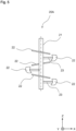
- FIG. 5 is a schematic configuration diagram of a stirring blade showing a second embodiment of the washing and drying apparatus.
- a stirring blade 20A has the shaft 21 and a plurality of fins 22 wound around the shaft 21 so as to form a discontinuous helix along the shaft 21.
- the plurality of supports 23 extending perpendicularly to the shaft center of the shaft 21 are attached to the shaft 21, and the respective fins 22 are supported by the respective supports 23.
- the fins 22, 22 adjacent to each other in the helical direction are spaced apart.
- a platelike baffle may be placed on the inner surface 111a of the sidewall part 111 of the container main body 11 toward the central axis 11a.
- the above-described configuration can reduce the degree of stirring with the stirring blade 20A as compared with the fin 22 of the first embodiment that forms a continuous helix.
- the treatment target and the washing liquid can be dropped through a gap between the fins 22, 22 adjacent to each other in the helical direction, which enables the treatment target and the washing liquid to be recovered with high efficiency.
- FIG. 6 is a top view showing a third embodiment of the washing and drying apparatus.
- the third embodiment differs from the first embodiment in that a spray nozzle is provided.
- the different component will be described below.
- the remaining components are the same as the components of the first embodiment, and are denoted by the same reference numerals as the reference numerals in the first embodiment and description thereof will be omitted.
- a container 10B has spray nozzles 18 communicating with the washing liquid supply tubes 13 and capable of spraying the washing liquid. Specifically describing, the spray nozzles 18 spread the washing liquid radially.
- the spray nozzles 18 are attached to an inner surface of the top part 112 at the inner side of the container main body 11.
- the plurality of washing liquid supply tubes 13 are provided, and the spray nozzles 18 communicate with the respective washing liquid supply tubes 13. In the present embodiment, four of each of the washing liquid supply tubes 13 and the spray nozzles 18 are provided.
- the above-described configuration enables the treatment target to be washed while spraying and discharging the washing liquid, so that the container 10B can be made smaller than in the case of storing the washing liquid in the container 10B and washing the treatment target.
- all of the spray nozzles 18 are arranged so as to have an evenly-spaced central angle around the central axis 11a when viewed in the direction along the central axis 11a of the container main body 11. This enables the washing liquid to be emitted uniformly to all of the regions in the container main body 11 when viewed in the direction along the central axis 11a, which can shorten the washing time and can reduce the quantity of the washing liquid.
- all of the spray nozzles 18 are arranged at positions at the half of the distance from the central axis 11a to the inner surface 111a of the sidewall part 111 when viewed in the direction along the central axis 11a of the container main body 11. This enables the washing liquid to be emitted more uniformly to all of the regions in the container main body 11 when viewed in the direction along the central axis 11a, which can further shorten the washing time and can further reduce the quantity of the washing liquid.
- one spray nozzle 18 may be provided, but it is preferable to provide a plurality of spray nozzles 18. In particular, it is preferable to provide four to six spray nozzles 18, which enables the washing liquid to be emitted uniformly to all of the regions in the container main body 11.
- washing liquid discharge holes are present, but at least one washing liquid discharge hole (filter) may be present.
- three washing liquid discharge tubes are present, but at least one washing liquid discharge tube may be present.
- the number of the treatment target supply holes, the washing liquid supply holes, and the treatment target discharge holes may be increased.
- the number of the treatment target supply tubes, the washing liquid supply tubes, and the treatment target discharge tubes may be increased.
- the fin of the stirring blade forms a helix, but may not form a helix, and the number of the fins may be increased and/or decreased.
- the heater is provided in the sidewall part and the bottom part, but may further be provided in the top part, or may be provided in at least one of the top part, the sidewall part, and the bottom part.
- Example 1 shows Example 1 in which the above-described washing and drying apparatus was used to wash a treatment target.
- a result of Example 1 is shown in Table 1.
- Table 1 Capacity of Apparatus Resin Washing Method The Number of Times Example 1 100L ETFE Washing with Stored Water 6 Comparative Example 100L ETFE Washing with Stored Water 6
- Example 1 the washing and drying apparatus of the first embodiment was used to wash the treatment target. That is, the washing liquid was retained in the container to wash the treatment target.
- ETFE ethylene-tetrafluoroethylene copolymer
- Example 1 a 100-L vacuum washing and drying apparatus was used, and 100-mesh filters were used. The apparatus was charged with 25 kg of polymerized, unwashed powder as the treatment target and 25 kg of pure water as the washing liquid. After 30-minute stirring, water was discharged through the filters. This was repeated six times, and the electrical conductivity during the last water discharging was measured. It was confirmed that the electrical conductivity was less than or equal to 50 pS/cm which was a target value.
- ETFE was used as the treatment target.
- a 6000-L washing and drying apparatus having four plate stirring blades and a baffle was used to wash the treatment target.
- the container was charged with 1200 kg of polymerized, unwashed powder as the treatment target and 800 kg of pure water as the washing liquid, which were stirred for 60 minutes at sufficient revolutions per minute of stirring such that the powder was caught up in water. After washing by stirring, water was discharged. This was repeated six times. Thereafter, the polymer powder was collected and mixed with pure water, and an electrolyte remaining in the powder was evaluated in terms of electrical conductivity to confirm that the electrical conductivity was less than or equal to 50 pS/cm.
- the polymer powder was collected after each washing, and the powder and pure water were mixed, and pure water was then sampled to measure the electrical conductivity of pure water, similarly to Example 1.
- the powder was washed until it was confirmed that the electrical conductivity became less than or equal to 50 pS/cm which was the target value.
- Example 1 Both in Example 1 and the comparative example, it was confirmed that the electrical conductivity became less than or equal to 50 pS/cm which was the target value by repeating washing six times. As described above, it was found that Example 1 did not degrade washing capability as compared with the comparative example.
- the following shows an example about optimum values of the filter size.
- the container main body 11 with an outer diameter of ⁇ 2800 mm was used, and the filters 30 with an outer diameter of ⁇ 404 mm were used.
- the area of the filter 30 was calculated from the outer diameter of the filter 30.
- the proportion of the area of the filters 30 to the area (hereinafter referred to as the whole area) of the inner surface 113e of the bottom part 113 was calculated as the occupancy rate of the filters 30.
- Each of the filters 30 thus had an occupancy rate of 2%.
- the region R shall include the area occupied by a reinforcing component for attaching the filter 30 to the bottom part 113 in addition to the area of the filter 30.
- the region R is a region that defines the filter 30 in a sector in which the filter 30 is inscribed and which is indicated by a dash-double-dot line around the central axis 11a.
- an effective heat transfer area a value obtained by subtracting the area of the region R of each of the filters 30 from the whole area
- the proportion of the effective heat transfer area to the whole area is referred to as an effective heat transfer area rate.
- Table 2 shows a relationship among the number of filters, a water discharging time, and a drying time.
- Table 2 The Number of Filters Polywater Dehydrating Time Washing and Dehydrating Time The Number of Times of Discharging Water Total Water Discharging Time Drying Time Total Time 3 30 mins 30 mins 4 150 mins 409 mins 559 mins 6 15 mins 15 mins 4 75 mins 449 mins 524 mins 7 13 mins 13 mins 4 65 mins 467 mins 532 mins
- the polywater dehydrating time is a time required for discharging water used when the treatment target is polymerized after transfer to a washing and drying machine.
- the washing and dehydrating time is a time required for washing the treatment target and discharging water in a single washing step.
- the number of times of discharging water is the number of times of washing the treatment target and discharging water, and is the number of times of performing the washing step.
- the total water discharging time is a time required for the whole water discharging, and is obtained by (polywater dehydrating time + washing and dehydrating time ⁇ the number of times of discharging water).
- the drying time is a time required for drying the treatment target. That is, the drying time is a time required for drying the treatment target after water is discharged.
- the total time is a time required for the whole water discharging and drying, and is obtained by (total water discharging time + drying time).
- the total time was shorter by 35 minutes than in a case in which the number of filters was three. That is, the total water discharging time was shorter by 75 minutes, and the drying time was longer by 40 minutes.
- the total time was shorter by 27 minutes than in the case in which the number of filters was three. That is, the total water discharging time was shorter by 85 minutes, and the drying time was longer by 58 minutes. This reveals that an optimum number of filters is six.
- a filter having a larger area is more advantageous in terms of water discharging, and a filter having a smaller area is more advantageous for ensuring the heat transfer area in terms of drying.
- optimum values of the size of the filters are such that the occupancy rate of the filters is more than or equal to 2% and less than or equal to 20%, preferably more than or equal to 4% and less than or equal to 16%, and more preferably more than or equal to 6% and less than or equal to 12%.
- the number of filters is more than or equal to one and less than or equal to ten, preferably more than or equal to two and less than or equal to eight, and more preferably more than or equal to three and less than or equal to six.
Landscapes
- Engineering & Computer Science (AREA)
- Mechanical Engineering (AREA)
- General Engineering & Computer Science (AREA)
- Life Sciences & Earth Sciences (AREA)
- Microbiology (AREA)
- Cleaning By Liquid Or Steam (AREA)
- Drying Of Solid Materials (AREA)
Abstract
Description
- The present disclosure relates to a washing and drying apparatus for washing and drying a treatment target which is powder and made of a polymeric organic compound and a method for washing and drying the treatment target which is powder and made of the polymeric organic compound.
- A washing apparatus and a drying apparatus have conventionally been used separately for washing and drying a treatment target made of a polymerizable organic compound.
- The washing apparatus has a container main body and a stirring blade, holds a treatment target and water in the container main body, and washes the treatment target with water by rotation of the stirring blade. The drying apparatus has a rotatable container main body, holds the treatment target after being washed in the container main body, and dries the treatment target while rotating the container main body (
JP 61-130893 U1 - Patent Literature 1:
JP 61-130893 U1 - However, the separate use of the washing apparatus and the drying apparatus as in the conventional case requires a large space for placing the washing apparatus and the drying apparatus, and increases a workload for moving the treatment target from the washing apparatus to the drying apparatus.
- Therefore, an object of the present disclosure is to provide a washing and drying apparatus and a washing and drying method that can save space for placing the apparatus and reduce a workload.
- In order to solve the problems, a washing and drying apparatus which is a first aspect of the present disclosure is an apparatus capable of washing a treatment target which is powder and made of a polymeric organic compound (e.g., consist of a polymeric organic compound) with a washing liquid and drying the treatment target. The washing and drying apparatus includes a container, a stirring blade arranged inside the container and capable of rotating, a filter arranged in the container and capable of separately filtering the treatment target and the washing liquid, a heater arranged in the container and capable of heating an inside of the container, and a control device that rotates the stirring blade at a time of washing and a time of drying the treatment target and actuates the heater at the time of drying. The container has a container main body, a treatment target supply tube communicating with the inside of the container main body and capable of supplying the treatment target, a washing liquid supply tube communicating with the inside of the container main body and capable of supplying the washing liquid, a treatment target discharge tube communicating with the inside of the container main body and capable of discharging the treatment target, and a washing liquid discharge tube communicating with the inside of the container main body and capable of discharging the washing liquid. The filter is provided for the container main body and located at an upstream side of the washing liquid discharge tube.
- Preferably, a second aspect is the washing and drying apparatus of the first aspect, in which the filter is capable of separately filtering the washing liquid and the treatment target of more than or equal to 50 pm.
- Preferably, a third aspect is the washing and drying apparatus of the first or second aspect, in which the stirring blade has a shaft and a fin wound around the shaft so as to form a continuous helix along the shaft.
- Preferably, a fourth aspect is the washing and drying apparatus of the first or second aspect, in which the stirring blade has a shaft and a plurality of fins wound around the shaft so as to form a discontinuous helix along the shaft.
- Preferably, a fifth aspect is the washing and drying apparatus of any one of the first to fourth aspects, in which the stirring blade is capable of revolving while rotating.
- Preferably, a sixth aspect is the washing and drying apparatus of any one of the first to fifth aspects, further including a decompression device capable of decompressing the inside of the container.
- Preferably, a seventh aspect is the washing and drying apparatus of any one of the first to sixth aspects, in which the container is capable of retaining the washing liquid at the time of washing.
- Preferably, an eighth aspect is the washing and drying apparatus of any one of the first to sixth aspects, in which the container has a spray nozzle communicating with the washing liquid supply tube and capable of spraying the washing liquid.
- Preferably, a ninth aspect is the washing and drying apparatus of any one of the first to eighth aspects, in which the treatment target is made of resin.
- Preferably, a tenth aspect is the washing and drying apparatus of any one of the first to eighth aspects, in which the treatment target is made of fluororesin.
- Preferably, an eleventh aspect is the washing and drying apparatus of any one of the first to tenth aspects, in which the treatment target has an average particle size of more than or equal to 20 pm.
- Preferably, a twelfth aspect is the washing and drying apparatus of any one of the first to eleventh aspects, in which the container main body has a cylindrical sidewall part, a top part attached to a first opening of the sidewall part, and a bottom part attached to a second opening of the sidewall part, the bottom part has a treatment target discharge hole communicating with the treatment target discharge tube and a washing liquid discharge hole communicating with the washing liquid discharge tube, and the filter is provided at the washing liquid discharge hole.
- Preferably, a thirteenth aspect is the washing and drying apparatus of the twelfth aspect, in which the filter is arranged in a region closer to an outer circumference of the bottom part.
- Preferably, a fourteenth aspect is the washing and drying apparatus of the thirteenth aspect, in which part of the heater is arranged in a region closer to a center of the bottom part.
- Preferably, a fifteenth aspect is the washing and drying apparatus of any one of the twelfth to fourteenth aspects, in which an inner surface of the bottom part at an inner side of the container main body is flat, and the filter is provided on the inner surface.
- Preferably, a sixteenth aspect is the washing and drying apparatus of any one of the twelfth to fifteenth aspects, in which the treatment target discharge hole and the washing liquid discharge hole are arranged in a circumferential direction around a central axis of the container main body when viewed in a direction along the central axis.
- Preferably, a seventeenth aspect is the washing and drying apparatus of the sixteenth aspect, in which the washing liquid discharge hole includes a plurality of washing liquid discharge holes, and the treatment target discharge hole and the washing liquid discharge holes are arranged so as to have an evenly-spaced central angle around the central axis.
- Preferably, an eighteenth aspect is the washing and drying apparatus of the sixteenth or seventeenth aspect, in which the washing liquid discharge hole includes a plurality of washing liquid discharge holes, the top part has a treatment target supply hole communicating with the treatment target supply tube and a washing liquid supply hole communicating with the washing liquid supply tube, and an opening of the treatment target supply hole at the inner side of the container main body and an opening of the washing liquid supply hole at the inner side of the container main body are located between any washing liquid discharge holes adjacent to each other in the circumferential direction among the washing liquid discharge holes when viewed in the direction along the central axis.
- Preferably, a nineteenth aspect is the washing and drying apparatus of any one of the sixteenth to eighteenth aspects, in which the washing liquid discharge hole includes a plurality of washing liquid discharge holes, and an inner circumferential trajectory of the fin of the stirring blade traced by rotation of the stirring blade crosses the treatment target discharge hole and the washing liquid discharge holes when viewed in the direction along the central axis.
- Preferably, a method for washing and drying a treatment target being powdery and made of a polymeric organic compound of a twentieth aspect includes washing a treatment target which is powder and made of a polymeric organic compound with a washing liquid while rotating a stirring blade and discharging the washing liquid through a filter to separately filter the treatment target and the washing liquid, and actuating a heater while rotating the stirring blade to dry the treatment target.
- The washing and drying apparatus and the washing and drying method according to an aspect of the present disclosure can save space for placing the apparatus and reduce a workload.
-
- [
Figure 1] Figure 1 is a simplified configuration diagram showing a first embodiment of a washing and drying apparatus. - [
Figure 2] Figure 2 is a top view of the washing and drying apparatus. - [
Figure 3] Figure 3 is an XY sectional view of the washing and drying apparatus when viewed from above. - [
Figure 4] Figure 4 is an XY sectional view of the washing and drying apparatus when viewed from above. - [
Figure 5] Figure 5 is a schematic configuration diagram of a stirring blade showing a second embodiment of the washing and drying apparatus. - [
Figure 6] Figure 6 is a top view showing a third embodiment of the washing and drying apparatus. - [
Figure 7] Figure 7 is an XY sectional view of Example 2 of the washing and drying apparatus when viewed from above. - Hereinafter, a washing and drying apparatus and a washing and drying method according to an aspect of the present disclosure will be described in detail in accordance with illustrated embodiments. Note that the drawings may partially include schematic ones, and actual dimensions and proportions are not reflected in some cases.
-
Figure 1 is a simplified configuration diagram showing a first embodiment of a washing and drying apparatus.Figure 2 is a top view of the washing and drying apparatus.Figure 3 is an XY sectional view of the washing and drying apparatus when viewed from above. - Note that as shown in the drawings, the vertical direction (a height direction) when a washing and
drying apparatus 1 is placed is referred to as a Z-direction, and the horizontal direction is referred to as an X-direction and a Y-direction. The X-direction, the Y-direction, and the Z-direction are directions perpendicular to one another, and constitute the right-handed system when arrayed in the order to X, Y, and Z. The forward direction of the Z-direction is referred to as an upper direction, and the reverse direction of the Z-direction is referred to as a lower direction. - As shown in
Figure 1 ,Figure 2 , andFigure 3 , the washing anddrying apparatus 1 is an apparatus capable of washing a treatment target which is powder and made of a polymeric organic compound with a washing liquid and drying the treatment target. The washing anddrying apparatus 1 includes acontainer 10, a stirringblade 20 arranged inside thecontainer 10, afilter 30 arranged in thecontainer 10, aheater 40 arranged in thecontainer 10, and acontrol device 5 that controls the stirringblade 20 and theheater 40. - The
container 10 has a containermain body 11, a treatmenttarget supply tube 12 attached to the containermain body 11, a washingliquid supply tube 13, a treatmenttarget discharge tube 14, and a washingliquid discharge tube 15. The treatmenttarget supply tube 12 communicates with the inside of the containermain body 11 and is capable of supplying the treatment target. The washingliquid supply tube 13 communicates with the inside of the containermain body 11 and is capable of supplying the washing liquid. The treatmenttarget discharge tube 14 communicates with the inside of the containermain body 11 and is capable of discharging the treatment target. The washingliquid discharge tube 15 communicates with the inside of the containermain body 11 and is capable of discharging the washing liquid. - The stirring
blade 20 is capable of rotating by driving of amotor 6 attached to the containermain body 11. The stirringblade 20 is capable of stirring the treatment target and the washing liquid at the time of washing the treatment target, and is capable of stirring the treatment target at the time of drying the treatment target. - The
filter 30 is provided for the containermain body 11 and located at the upstream side of the washingliquid discharge tube 15. Thefilter 30 is capable of separately filtering the treatment target and the washing liquid. - The
heater 40 is capable of heating the inside of thecontainer 10. Theheater 40 is capable of heating the treatment target at the time of drying the treatment target. - The
control device 5 rotates the stirringblade 20 at the times of washing and drying the treatment target. Specifically describing, thecontrol device 5 drives themotor 6 to rotate thestirring blade 20. Thecontrol device 5 also actuates theheater 40 at the time of drying the treatment target. - The above-described configuration enables the treatment target to be supplied from the treatment
target supply tube 12 into the containermain body 11 and the washing liquid to be supplied from the washingliquid supply tube 13 into the containermain body 11. Then, the treatment target can be washed with the washing liquid while thestirring blade 20 is being rotated. When the washing liquid is discharged (at the time of dehydration), the treatment target and the washing liquid can be filtered separately by thefilter 30. Specifically describing, the treatment target can be discharged from the treatmenttarget discharge tube 14, and the washing liquid can be discharged from the washingliquid discharge tube 15. Thereafter, theheater 40 can be actuated while thestirring blade 20 is being rotated to dry the treatment target. - Consequently, a washing step and a drying step can be performed with a single apparatus without the need to use a washing apparatus and a drying apparatus separately, which can save the space for placing the apparatus. In addition, since the washing step and the drying step can be performed with a single apparatus, there is no need to move the treatment target from a washing apparatus to a drying apparatus, which can reduce a workload.
- It is also conceivable to perform the washing step and the drying step with a conventionally-used washing apparatus; however, the washing step requires water (the washing liquid) and the treatment target to be distributed as uniformly as possible, so that the revolutions per minute of the stirring blade need to be increased. On the other hand, in the drying step, only the treatment target is stirred with no water contained, which may increase resistance against the treatment target and may apply a load on the stirring blade. Thus, the revolutions per minute of the stirring blade need to be reduced. Consequently, it is difficult to perform the drying step with the conventionally-used washing apparatus.
- Herein, having studied earnestly and paying attention to the fact that a treatment target which is powder and made of a polymeric organic compound is readily isolated from water, the inventor of the present application has found out that the treatment target can be washed by stirring both the treatment target and water without uniformly distributing the treatment target and water. That is, the inventor of the present application has found out that it is not necessary to increase the revolutions per minute of the stirring blade for uniform distribution and the treatment target can be washed even at lower revolutions per minute of the stirring blade.
- Paying attention to the fact that particularly in a case in which the treatment target is made of fluororesin, the treatment target has high water-repellency and the powdery treatment target and water are isolated completely in a stationary state, the inventor of the present application has found out that the treatment target can be washed by thus stirring both water and the powdery treatment target and bringing water and the powdery treatment target into contact only at the solid-liquid interface.
- As described above, the inventor of the present application has found out that the treatment target which is powder and made of a polymeric organic compound can be washed even at low revolutions per minute of the stirring blade at the time of drying, and has invented the washing and drying apparatus of the invention of the present application capable of performing the washing step and the drying step.
- The treatment target is made of resin, for example. Thus, the treatment target is readily isolated from water and can be washed even at lower revolutions per minute of the
stirring blade 20. Consequently, a load on thestirring blade 20 at the time of washing can be reduced. - The treatment target is preferably made of fluororesin. Since fluororesin has high water-repellency, the treatment target is more readily isolated from water and can be washed even at still lower revolutions per minute of the
stirring blade 20. Consequently, a load on thestirring blade 20 at the time of washing can be reduced further. - The treatment target has an average particle size of more than or equal to 20 µm, for example. Herein, the average particle size indicates a particle size at an integrated value of 50% in a particle size distribution obtained by the laser diffraction method.
- The washing liquid is water, for example. Note that the washing liquid may be an organic solvent such as ethyl alcohol or methyl alcohol.
- In a state in which the treatment target is dried, the washing liquid contained in the treatment target after being dried has a water content of 0.2%, preferably less than or equal to 0.1%.
- The container
main body 11 has acylindrical sidewall part 111, atop part 112 attached to a first opening at the upper side of thesidewall part 111, and abottom part 113 attached to a second opening at the lower side of thesidewall part 111. Thesidewall part 111 has a cylindrical shape, for example. Thetop part 112 and thebottom part 113 have a disc shape, for example. - A
central axis 11a of the containermain body 11 conforms to a central axis of thecylindrical sidewall part 111. A center of thetop part 112 crosses thecentral axis 11a of the containermain body 11. Acenter 113d of thebottom part 113 crosses thecentral axis 11a of the containermain body 11. - The
top part 112 has a treatmenttarget supply hole 112a communicating with the treatmenttarget supply tube 12 and a washingliquid supply hole 112b communicating with the washingliquid supply tube 13. One each of the treatmenttarget supply hole 112a and the washingliquid supply hole 112b are provided. - The
bottom part 113 has a treatmenttarget discharge hole 113a communicating with the treatmenttarget discharge tube 14 and a washingliquid discharge hole 113b communicating with the washingliquid discharge tube 15. One treatmenttarget discharge hole 113a and three washing liquid discharge holes 113b are provided. Each of the washingliquid discharge holes 113b is provided with thefilter 30. The provision of the treatmenttarget discharge hole 113a and the washing liquid discharge holes 113b in thebottom part 113 thus enables both the washing liquid and the treatment target to be discharged with high efficiency by gravity. - The treatment
target supply tube 12 and the washingliquid supply tube 13 are attached to thetop part 112. One each of the treatmenttarget supply tube 12 and the washingliquid supply tube 13 are provided. - The treatment
target discharge tube 14 and the washingliquid discharge tube 15 are attached to thebottom part 113. One treatmenttarget discharge tube 14 and three washingliquid discharge tubes 15 are provided. Afirst sluice valve 16 is attached to the treatmenttarget discharge tube 14, and asecond sluice valve 17 is attached to the washingliquid discharge tube 15. - The
container 10 is preferably provided with adecompression device 8 capable of decompressing the inside of thecontainer 10. Specifically describing, thedecompression device 8 is connected to the containermain body 11 via abag filter 7 attached to thetop part 112. Thebag filter 7 can prevent the treatment target from being absorbed into thedecompression device 8 when thedecompression device 8 decompresses the inside of thecontainer 10. The above-described configuration enables the inside of thecontainer 10 to be decompressed by thedecompression device 8 at the time of drying to dry the treatment target at low temperature. - The
container 10 is capable of retaining the washing liquid at the time of washing. Specifically describing, at the time of washing, the first andsecond sluice valves liquid supply tube 13 into the containermain body 11, so that the washing liquid can be retained in the containermain body 11. The above-described configuration enables the washing liquid to be stored in thecontainer 10 to wash the treatment target, which can reduce the quantity of the washing liquid as compared with a case of washing the treatment target while spraying the washing liquid. - The stirring
blade 20 has ashaft 21 and afin 22 wound around theshaft 21 so as to form a continuous helix along theshaft 21. Specifically describing, a plurality ofsupports 23 extending perpendicularly to a shaft center of theshaft 21 are attached to theshaft 21, and thefin 22 is supported by thesupports 23. The stirringblade 20 is attached to the containermain body 11 such that the shaft center of theshaft 21 conforms to thecentral axis 11a of the containermain body 11. The stirringblade 20 rotates around thecentral axis 11a. The above-described configuration can increase the degree of stirring with the stirringblade 20 because thefin 22 forms a continuous helix. - Note that the stirring blade may be capable of revolving while rotating. Specifically describing, the stirring blade may be attached to the container
main body 11 such that the shaft center of the shaft is offset from thecentral axis 11a of the containermain body 11, and the stirring blade may revolve around thecentral axis 11a while rotating around the shaft center of theshaft 21. The above-described configuration enables more reliable stirring with the stirringblade 20. - The
filters 30 are attached to openings of the washing liquid discharge holes 113b at the inner side of the containermain body 11. Preferably, thefilters 30 are capable of separately filtering the washing liquid and the treatment target of more than or equal to 50 µm. The above-described configuration enables the washing liquid and the treatment target to be filtered separately. Thefilters 30 are composed of metal such as stainless steel or resin such as polyester or polyethylene, for example. Adjustment of a mesh size of thefilters 30 enables treatment targets having various sizes to be filtered separately. - The
heater 40 is provided in thesidewall part 111 and thebottom part 112 of the containermain body 11. Specifically describing, theheater 40 has a plurality ofpipes 41, and the plurality ofpipes 41 are buried in each of thesidewall part 111 and thebottom part 112. The inside of the containermain body 11 can be heated by flowing a heating medium such as steam, oil, or warm water through thepipes 41. - Note that the
pipes 41 may be replaced by halved pipes, which can reduce cost. Alternatively, thepipes 41 may be replaced by an electric heater, which enables a more compact arrangement. - The
control device 5 rotates the stirringblade 20 at the time of washing the treatment target, and actuates theheater 40 while rotating the stirringblade 20 at the time of drying the treatment target. Preferably, thecontrol device 5 actuates theheater 40 at the time of washing the treatment target. The temperature rise at the time of washing can thus improve a washing effect. - The
control device 5 equalizes the revolutions per minute of thestirring blade 20 at the time of washing and the revolutions per minute of thestirring blade 20 at the time of drying. For example, the revolutions per minute of thestirring blade 20 are 5 to 100 rpm, preferably 30 to 100 rpm. - Note that the
control device 5 may make the revolutions per minute of thestirring blade 20 at the time of drying the treatment target lower than the revolutions per minute of thestirring blade 20 at the time of washing the treatment target. For example, the revolutions per minute of thestirring blade 20 at the time of drying are 30 rpm, and the revolutions per minute of thestirring blade 20 at the time of washing are 50 to 100 rpm. Since the treatment target alone is stirred at the time of drying without the washing liquid contained, the resistance against the treatment target increases; however, the load to be applied to thestirring blade 20 can be reduced further by reducing the revolutions per minute of thestirring blade 20. - As shown in
Figure 3 , thefilters 30 are arranged in a region closer to theouter circumference 113c of thebottom part 113. The region closer to theouter circumference 113c of thebottom part 113 refers to a region closer to theouter circumference 113c of thebottom part 113 than to the half of the distance from thecenter 113d of thebottom part 113 to aninner surface 111a of thesidewall part 111 when viewed in the direction along thecentral axis 11a of the containermain body 11. Theinner surface 111a of thesidewall part 111 faces an internal space of the containermain body 11. - In
Figure 3 , the position of the half of the distance from thecenter 113d of the bottom part 113 (thecentral axis 11a of the container main body 11) to theinner surface 111a of thesidewall part 111 is indicated by an imaginary circle C. That is, the region closer to theouter circumference 113c of thebottom part 113 is a region closer to theouter circumference 113c than to the imaginary circle C. - The expression that the
filters 30 are arranged in the region closer to theouter circumference 113c of thebottom part 113 includes not only a case in which all of thefilters 30 are arranged in the region closer to theouter circumference 113c of thebottom part 113, but also a case in which half or more of thefilters 30 are arranged in the region closer to theouter circumference 113c of thebottom part 113. In the present embodiment, all of thefilters 30 are arranged in the region closer to theouter circumference 113c of thebottom part 113. - When discharging the washing liquid, the above-described configuration enables the washing liquid to be splashed to the region closer to the
outer circumference 113c of thebottom part 113 by centrifugal force of thestirring blade 20 by rotating the stirringblade 20, and enables the treatment target and the washing liquid to be filtered separately with high efficiency by thefilters 30. - As shown in
Figure 3 , part of theheater 40 is arranged in a region closer to thecenter 113d of thebottom part 113. Specifically describing, some of thepipes 41 are arranged in the region closer to thecenter 113d of thebottom part 113. The region closer to thecenter 113d of thebottom part 113 refers to a region closer to thecenter 113d of thebottom part 113 than to the half of the distance from the center of thebottom part 113 to theinner surface 111a of thesidewall part 111 when viewed in the direction along thecentral axis 11a of the containermain body 11. That is, the region closer to thecenter 113d of thebottom part 113 is a region closer to thecenter 113d than to the imaginary circle C. - With the above-described configuration, part of the
heater 40 is arranged in the region closer to thecenter 113d of thebottom part 113, so that the vicinity of thecentral axis 11a of the containermain body 11, which is difficult to heat, can be heated effectively at the time of drying to dry the treatment target effectively. As described above, adjustment of the arrangement of thefilters 30 and theheater 40 at thebottom part 113 enables both discharging of the washing liquid at the time of washing and drying of the treatment target at the time of drying to be performed with high efficiency. - As shown in
Figure 3 , aninner surface 113e of thebottom part 113 at the inner side of the containermain body 11 is flat, and thefilters 30 are provided on theinner surface 113e. Theinner surface 113e of thebottom part 113 faces the internal space of the containermain body 11. Preferably, thefilters 30 are located flush with theinner surface 113e. The above-described configuration enables the area of thefilters 30 to be ensured widely while maintaining thefilters 30 flatly because theinner surface 113e of thebottom part 113 is flat. - As shown in
Figure 3 , the treatmenttarget discharge hole 113a and the washing liquid discharge holes 113b are arranged in the circumferential direction around thecentral axis 11a when viewed in the direction along thecentral axis 11a of the containermain body 11. Specifically describing, an opening of the treatmenttarget discharge hole 113a at the inner side of the containermain body 11 and openings of the washing liquid discharge holes 113b at the inner side of the containermain body 11 are arranged in the circumferential direction. In other words, thefilters 30 and the treatmenttarget discharge hole 113a are arranged in the circumferential direction. The above-described configuration enables the treatmenttarget discharge hole 113a and the washing liquid discharge holes 113b to be arranged in correspondence to the direction in which thestirring blade 20 rotates, so that the washing liquid can be discharged from the washing liquid discharge holes 113b with high efficiency, and the treatment target can be recovered through the treatmenttarget discharge hole 113a with high efficiency. - Preferably, the plurality of washing liquid discharge holes 113b are present, and all of the treatment
target discharge hole 113a and the washing liquid discharge holes 113b are arranged so as to have an evenly-spaced central angle around thecentral axis 11a. In the present embodiment, the one treatmenttarget discharge hole 113a and the three washing liquid discharge holes 113b are arranged so as to have a central angle of 90°. The above-described configuration enables the washing liquid to be discharged from the plurality of washing liquid discharge holes 113b with high efficiency. -
Figure 4 is an XY sectional view of the washing and drying apparatus when viewed from above. As shown inFigure 4 , the plurality of washing liquid discharge holes 113b are present, and an opening of the treatmenttarget supply hole 112a at the inner side of the containermain body 11 and an opening of the washingliquid supply hole 112b at the inner side of the containermain body 11 are located between the washingliquid discharge holes central axis 11a. Specifically describing, projections of the respective openings of the treatmenttarget supply hole 112a and the washingliquid supply hole 112b are indicated by dash-double-dot lines. These openings are located between thefilters - The above-described configuration reduces direct dropping of the treatment target and the washing liquid onto the
filters 30, the treatment target being supplied from the treatmenttarget supply tube 12 into the containermain body 11 and the washing liquid being supplied from the washingliquid supply tube 13 into the containermain body 11, which can reduce damage to thefilters 30. - As shown in
Figure 4 , the plurality of washing liquid discharge holes 113b are present, and an innercircumferential trajectory 22a of thefin 22 of thestirring blade 20 traced by rotation of thestirring blade 20 crosses the treatmenttarget discharge hole 113a and the washing liquid discharge holes 113b when viewed in the direction along thecentral axis 11a. In other words, the innercircumferential trajectory 22a of thefin 22 crosses thefilters 30 when viewed in the direction along thecentral axis 11a. An outercircumferential trajectory 22b of thefin 22 is close to theinner surface 111a of thesidewall part 111. - With the above-described configuration, the
fin 22 of thestirring blade 20 passes directly above the treatmenttarget discharge hole 113a and the washing liquid discharge holes 113b while thestirring blade 20 is rotating. This enables the washing liquid dropped from the inner circumferential side of thefin 22 to be recovered effectively through the washing liquid discharge holes 113b, and enables the treatment target dropped from the inner circumferential side of thefin 22 to be recovered effectively through the treatmenttarget discharge hole 113a. - Preferably, the inner
circumferential trajectory 22a of thefin 22 crosses the region closer to theouter circumference 113c of thebottom part 113 than to acenter 30a of thefilter 30 when viewed in the direction along thecentral axis 11a. This enables the washing liquid dropped from the inner circumferential side of thefin 22 to be recovered more effectively through the washing liquid discharge holes 113b. - Next, a method for washing and drying the treatment target which is powder and made of a polymeric organic compound with the washing liquid and drying the treatment target will be described.
- As shown in
Figure 1 , the treatment target is supplied from the treatmenttarget supply tube 12 into the containermain body 11, and the washing liquid is supplied from the washingliquid supply tube 13 into the containermain body 11. The treatment target and the washing liquid may be supplied at different timings or may be supplied simultaneously. - Thereafter, the treatment target is washed with the washing liquid while the
stirring blade 20 is being rotated, and the washing liquid is discharged through thefilters 30 to separately filter the treatment target and the washing liquid. Thefirst sluice valve 16 and thesecond sluice valve 17 are closed at the time of washing, and thefirst sluice valve 16 is closed and thesecond sluice valve 17 is opened at the time of discharging water. Note that water may be discharged after washing the treatment target, or may be discharged while the treatment target is being washed. In addition, washing and water discharging may be repeated a plurality of times. - Thereafter, the
heater 40 is actuated while thestirring blade 20 is being rotated to dry the treatment target. At this time, thefirst sluice valve 16 and thesecond sluice valve 17 are closed. At this time, when thedecompression device 8 is actuated, the treatment target can be dried at low temperature. Note that thesecond sluice valve 17 may be opened in the latter half of drying to dry the treatment target while air is being delivered into the containermain body 11. - Thereafter, the
first sluice valve 16 is opened and thesecond sluice valve 17 is closed to recover the treatment target through the treatmenttarget discharge tube 14. - The above-described a method for washing and drying the treatment target which is powder and made of the polymeric organic compound enables the washing step and the drying step to be performed with a single apparatus without the need to use a washing apparatus and a drying apparatus separately, which can save the space for placing the apparatus. In addition, since the washing step and the drying step can be performed with a single apparatus, there is no need to move the treatment target from a washing apparatus to a drying apparatus, which can reduce a workload.
-
Figure 5 is a schematic configuration diagram of a stirring blade showing a second embodiment of the washing and drying apparatus. As shown inFigure 5 , in the washing and drying apparatus of the second embodiment, astirring blade 20A has theshaft 21 and a plurality offins 22 wound around theshaft 21 so as to form a discontinuous helix along theshaft 21. Specifically describing, the plurality ofsupports 23 extending perpendicularly to the shaft center of theshaft 21 are attached to theshaft 21, and therespective fins 22 are supported by the respective supports 23. Thefins - Note that in order to improve mixing performance, a platelike baffle may be placed on the
inner surface 111a of thesidewall part 111 of the containermain body 11 toward thecentral axis 11a. - The above-described configuration can reduce the degree of stirring with the
stirring blade 20A as compared with thefin 22 of the first embodiment that forms a continuous helix. The treatment target and the washing liquid can be dropped through a gap between thefins -
Figure 6 is a top view showing a third embodiment of the washing and drying apparatus. The third embodiment differs from the first embodiment in that a spray nozzle is provided. The different component will be described below. The remaining components are the same as the components of the first embodiment, and are denoted by the same reference numerals as the reference numerals in the first embodiment and description thereof will be omitted. - As shown in
Figure 6 , in a washing and dryingapparatus 1B of the third embodiment, acontainer 10B hasspray nozzles 18 communicating with the washingliquid supply tubes 13 and capable of spraying the washing liquid. Specifically describing, thespray nozzles 18 spread the washing liquid radially. The spray nozzles 18 are attached to an inner surface of thetop part 112 at the inner side of the containermain body 11. The plurality of washingliquid supply tubes 13 are provided, and thespray nozzles 18 communicate with the respective washingliquid supply tubes 13. In the present embodiment, four of each of the washingliquid supply tubes 13 and thespray nozzles 18 are provided. - The above-described configuration enables the treatment target to be washed while spraying and discharging the washing liquid, so that the
container 10B can be made smaller than in the case of storing the washing liquid in thecontainer 10B and washing the treatment target. - Preferably, all of the
spray nozzles 18 are arranged so as to have an evenly-spaced central angle around thecentral axis 11a when viewed in the direction along thecentral axis 11a of the containermain body 11. This enables the washing liquid to be emitted uniformly to all of the regions in the containermain body 11 when viewed in the direction along thecentral axis 11a, which can shorten the washing time and can reduce the quantity of the washing liquid. - Preferably, all of the
spray nozzles 18 are arranged at positions at the half of the distance from thecentral axis 11a to theinner surface 111a of thesidewall part 111 when viewed in the direction along thecentral axis 11a of the containermain body 11. This enables the washing liquid to be emitted more uniformly to all of the regions in the containermain body 11 when viewed in the direction along thecentral axis 11a, which can further shorten the washing time and can further reduce the quantity of the washing liquid. - Note that one
spray nozzle 18 may be provided, but it is preferable to provide a plurality ofspray nozzles 18. In particular, it is preferable to provide four to sixspray nozzles 18, which enables the washing liquid to be emitted uniformly to all of the regions in the containermain body 11. - Although the embodiments have been described above, it will be understood that the embodiments and details may be modified variously without departing from the spirit and scope of claims. For example, the respective components of the first to third embodiments may be combined variously or replaced.
- In the above-described embodiments, three washing liquid discharge holes (filters) are present, but at least one washing liquid discharge hole (filter) may be present. Similarly, three washing liquid discharge tubes are present, but at least one washing liquid discharge tube may be present. In addition, the number of the treatment target supply holes, the washing liquid supply holes, and the treatment target discharge holes may be increased. Similarly, the number of the treatment target supply tubes, the washing liquid supply tubes, and the treatment target discharge tubes may be increased.
- In the above-described embodiments, the fin of the stirring blade forms a helix, but may not form a helix, and the number of the fins may be increased and/or decreased. In the above-described embodiments, the heater is provided in the sidewall part and the bottom part, but may further be provided in the top part, or may be provided in at least one of the top part, the sidewall part, and the bottom part.
- The following shows Example 1 in which the above-described washing and drying apparatus was used to wash a treatment target. A result of Example 1 is shown in Table 1.
[Table 1] Capacity of Apparatus Resin Washing Method The Number of Times Example 1 100L ETFE Washing with Stored Water 6 Comparative Example 100L ETFE Washing with Stored Water 6 - In Example 1, the washing and drying apparatus of the first embodiment was used to wash the treatment target. That is, the washing liquid was retained in the container to wash the treatment target. In addition, ETFE (ethylene-tetrafluoroethylene copolymer) was used as the treatment target.
- In Example 1, a 100-L vacuum washing and drying apparatus was used, and 100-mesh filters were used. The apparatus was charged with 25 kg of polymerized, unwashed powder as the treatment target and 25 kg of pure water as the washing liquid. After 30-minute stirring, water was discharged through the filters. This was repeated six times, and the electrical conductivity during the last water discharging was measured. It was confirmed that the electrical conductivity was less than or equal to 50 pS/cm which was a target value.
- Specifically describing, after each washing, 10 g of polymer powder was collected and put into a 100-ml screw tube together with 10 ml of pure water. After shaking the screw tube more than or equal to 100 times to sufficiently mix the powder and pure water, pure water was sampled to measure the electrical conductivity of pure water. The powder was washed until it was confirmed that the electrical conductivity became less than or equal to 50 pS/cm which was the target value.
- In a comparative example, ETFE was used as the treatment target. In the comparative example, a 6000-L washing and drying apparatus having four plate stirring blades and a baffle was used to wash the treatment target. The container was charged with 1200 kg of polymerized, unwashed powder as the treatment target and 800 kg of pure water as the washing liquid, which were stirred for 60 minutes at sufficient revolutions per minute of stirring such that the powder was caught up in water. After washing by stirring, water was discharged. This was repeated six times. Thereafter, the polymer powder was collected and mixed with pure water, and an electrolyte remaining in the powder was evaluated in terms of electrical conductivity to confirm that the electrical conductivity was less than or equal to 50 pS/cm.
- Specifically describing, the polymer powder was collected after each washing, and the powder and pure water were mixed, and pure water was then sampled to measure the electrical conductivity of pure water, similarly to Example 1. The powder was washed until it was confirmed that the electrical conductivity became less than or equal to 50 pS/cm which was the target value.
- Both in Example 1 and the comparative example, it was confirmed that the electrical conductivity became less than or equal to 50 pS/cm which was the target value by repeating washing six times. As described above, it was found that Example 1 did not degrade washing capability as compared with the comparative example.
- The following shows an example about optimum values of the filter size.
- As shown in
Figure 7 , the containermain body 11 with an outer diameter of ϕ2800 mm was used, and thefilters 30 with an outer diameter of ϕ404 mm were used. The area of thefilter 30 was calculated from the outer diameter of thefilter 30. The proportion of the area of thefilters 30 to the area (hereinafter referred to as the whole area) of theinner surface 113e of thebottom part 113 was calculated as the occupancy rate of thefilters 30. Each of thefilters 30 thus had an occupancy rate of 2%. - It was assumed that the area of the region R hatched by dotted lines in the drawing was lost for each of the
filters 30 as a heat transfer area. The region R shall include the area occupied by a reinforcing component for attaching thefilter 30 to thebottom part 113 in addition to the area of thefilter 30. Specifically describing, the region R is a region that defines thefilter 30 in a sector in which thefilter 30 is inscribed and which is indicated by a dash-double-dot line around thecentral axis 11a. Thus, a value obtained by subtracting the area of the region R of each of thefilters 30 from the whole area is referred to as an effective heat transfer area, and the proportion of the effective heat transfer area to the whole area is referred to as an effective heat transfer area rate. - Subsequently, Table 2 shows a relationship among the number of filters, a water discharging time, and a drying time.
[Table 2] The Number of Filters Polywater Dehydrating Time Washing and Dehydrating Time The Number of Times of Discharging Water Total Water Discharging Time Drying Time Total Time 3 30 mins 30 mins 4 150 mins 409 mins 559 mins 6 15 mins 15 mins 4 75 mins 449 mins 524 mins 7 13 mins 13 mins 4 65 mins 467 mins 532 mins - The polywater dehydrating time is a time required for discharging water used when the treatment target is polymerized after transfer to a washing and drying machine. The washing and dehydrating time is a time required for washing the treatment target and discharging water in a single washing step. The number of times of discharging water is the number of times of washing the treatment target and discharging water, and is the number of times of performing the washing step. The total water discharging time is a time required for the whole water discharging, and is obtained by (polywater dehydrating time + washing and dehydrating time × the number of times of discharging water).
- The drying time is a time required for drying the treatment target. That is, the drying time is a time required for drying the treatment target after water is discharged.
- The total time is a time required for the whole water discharging and drying, and is obtained by (total water discharging time + drying time).
- In a case in which the number of filters was six as shown in Table 2, the total time was shorter by 35 minutes than in a case in which the number of filters was three. That is, the total water discharging time was shorter by 75 minutes, and the drying time was longer by 40 minutes. In addition, in a case in which the number of filters was seven, the total time was shorter by 27 minutes than in the case in which the number of filters was three. That is, the total water discharging time was shorter by 85 minutes, and the drying time was longer by 58 minutes. This reveals that an optimum number of filters is six.
- In short, a filter having a larger area is more advantageous in terms of water discharging, and a filter having a smaller area is more advantageous for ensuring the heat transfer area in terms of drying.
- From the foregoing, six filters and an occupancy rate of 12% (an effective heat transfer area rate of 45%) of the filters were optimum for shortening the total cycle time from a balance between the heat transfer area and water discharging area. Note that in the above-described first embodiment, three filters and a filter occupancy rate of 6% (an effective heat transfer area rate of 68%) were adopted in terms of strength.
- Then, optimum values of the size of the filters are such that the occupancy rate of the filters is more than or equal to 2% and less than or equal to 20%, preferably more than or equal to 4% and less than or equal to 16%, and more preferably more than or equal to 6% and less than or equal to 12%. In other words, since a filter has an occupancy rate of 2%, the number of filters is more than or equal to one and less than or equal to ten, preferably more than or equal to two and less than or equal to eight, and more preferably more than or equal to three and less than or equal to six.
- This achieves a good balance between the water discharging time and the drying time with the occupancy rate of the filters falling within the above-described range, which can shorten the whole operation time. Note that when the occupancy rate of the filters is smaller than a lower limit value, the water discharging time increases, and when the occupancy rate of the filters is larger than an upper limit value, the drying time increases.
-
- 1, 1B washing and drying apparatus
- 5 control device
- 6 motor
- 7 bag filter
- 8 decompression device
- 10, 10B container
- 11 container main body
- 11a central axis
- 111 sidewall part
- 111a inner surface
- 112 top part
- 112a treatment target supply hole
- 112b washing liquid supply hole
- 113 bottom part
- 113a treatment target discharge hole
- 113b washing liquid discharge hole
- 113c outer circumference
- 113d center
- 113e inner surface
- 12 treatment target supply tube
- 13 washing liquid supply tube
- 14 treatment target discharge tube
- 15 washing liquid discharge tube
- 16, 17 first and second sluice valves
- 18 spray nozzle
- 20, 20A stirring blade
- 21 shaft
- 22 fin
- 22a inner circumferential trajectory
- 22b outer circumferential trajectory
- 30 filter
- 30a center
- 40 heater
- 41 pipe
- C imaginary circle
- R region
Claims (20)
- A washing and drying apparatus which is an apparatus capable of washing a treatment target which is powder and made of a polymeric organic compound with a washing liquid and drying the treatment target, the washing and drying apparatus comprising:a container;a stirring blade arranged inside the container and capable of rotating;a filter arranged in the container and capable of separately filtering the treatment target and the washing liquid;a heater arranged in the container and capable of heating an inside of the container; anda control device that rotates the stirring blade at a time of washing and a time of drying the treatment target and actuates the heater at the time of drying the treatment target, whereinthe container has a container main body, a treatment target supply tube communicating with the inside of the container main body and capable of supplying the treatment target, a washing liquid supply tube communicating with the inside of the container main body and capable of supplying the washing liquid, a treatment target discharge tube communicating with the inside of the container main body and capable of discharging the treatment target, and a washing liquid discharge tube communicating with the inside of the container main body and capable of discharging the washing liquid, andthe filter is provided for the container main body and located at an upstream side of the washing liquid discharge tube.
- The washing and drying apparatus according to claim 1, wherein the filter is capable of separately filtering the washing liquid and the treatment target of more than or equal to 50 µm.
- The washing and drying apparatus according to claim 1 or 2, wherein the stirring blade has a shaft and a fin wound around the shaft so as to form a continuous helix along the shaft.
- The washing and drying apparatus according to claim 1 or 2, wherein the stirring blade has a shaft and a plurality of fins wound around the shaft so as to form a discontinuous helix along the shaft.
- The washing and drying apparatus according to any one of claims 1 to 4, wherein the stirring blade is capable of revolving while rotating.
- The washing and drying apparatus according to any one of claims 1 to 5, further comprising a decompression device capable of decompressing the inside of the container.
- The washing and drying apparatus according to any one of claims 1 to 6, wherein the container is capable of retaining the washing liquid at the time of washing.
- The washing and drying apparatus according to any one of claims 1 to 6, wherein the container has a spray nozzle communicating with the washing liquid supply tube and capable of spraying the washing liquid.
- The washing and drying apparatus according to any one of claims 1 to 8, wherein the treatment target is made of resin.
- The washing and drying apparatus according to any one of claims 1 to 8, wherein the treatment target is made of fluororesin.
- The washing and drying apparatus according to any one of claims 1 to 10, wherein the treatment target has an average particle size of more than or equal to 20 pm.
- The washing and drying apparatus according to any one of claims 1 to 11, whereinthe container main body has a cylindrical sidewall part, a top part attached to a first opening of the sidewall part, and a bottom part attached to a second opening of the sidewall part,the bottom part has a treatment target discharge hole communicating with the treatment target discharge tube and a washing liquid discharge hole communicating with the washing liquid discharge tube, andthe filter is provided at the washing liquid discharge hole.
- The washing and drying apparatus according to claim 12, wherein the filter is arranged in a region closer to an outer circumference of the bottom part.
- The washing and drying apparatus according to claim 13, wherein a part of the heater is arranged in a region closer to a center of the bottom part.
- The washing and drying apparatus according to any one of claims 12 to 14, wherein an inner surface of the bottom part at an inner side of the container main body is flat, and the filter is provided on the inner surface.
- The washing and drying apparatus according to any one of claims 12 to 15, wherein the treatment target discharge hole and the washing liquid discharge hole are arranged in a circumferential direction around a central axis of the container main body when viewed in a direction along the central axis.
- The washing and drying apparatus according to claim 16, wherein the washing liquid discharge hole includes a plurality of washing liquid discharge holes, and the treatment target discharge hole and the washing liquid discharge holes are arranged so as to have an evenly-spaced central angle around the central axis.
- The washing and drying apparatus according to claim 16 or 17, whereinthe washing liquid discharge hole includes a plurality of washing liquid discharge holes,the top part has a treatment target supply hole communicating with the treatment target supply tube and a washing liquid supply hole communicating with the washing liquid supply tube, andan opening of the treatment target supply hole at the inner side of the container main body and an opening of the washing liquid supply hole at the inner side of the container main body are located between any washing liquid discharge holes adjacent to each other in the circumferential direction among the washing liquid discharge holes when viewed in the direction along the central axis.
- The washing and drying apparatus according to any one of claims 16 to 18, whereinthe washing liquid discharge hole includes a plurality of washing liquid discharge holes, andan inner circumferential trajectory of the fin of the stirring blade traced by rotation of the stirring blade crosses the treatment target discharge hole and the washing liquid discharge holes when viewed in the direction along the central axis.
- A method for washing and drying a treatment target which is powder and made of a polymeric organic compound, comprising:washing a treatment target which is powder and made of a polymeric organic compound with a washing liquid while rotating a stirring blade and discharging the washing liquid through a filter to separately filter the treatment target and the washing liquid; andactuating a heater while rotating the stirring blade to dry the treatment target.
Applications Claiming Priority (2)
| Application Number | Priority Date | Filing Date | Title |
|---|---|---|---|
| JP2021114345 | 2021-07-09 | ||
| PCT/JP2022/026741 WO2023282266A1 (en) | 2021-07-09 | 2022-07-05 | Washing/drying apparatus and washing/drying method |
Publications (2)
| Publication Number | Publication Date |
|---|---|
| EP4350263A1 true EP4350263A1 (en) | 2024-04-10 |
| EP4350263A4 EP4350263A4 (en) | 2024-08-28 |
Family
ID=84800695
Family Applications (1)
| Application Number | Title | Priority Date | Filing Date |
|---|---|---|---|
| EP22837680.2A Pending EP4350263A4 (en) | 2021-07-09 | 2022-07-05 | WASHER-DRYERS AND WASHER-DRYERS |
Country Status (4)
| Country | Link |
|---|---|
| EP (1) | EP4350263A4 (en) |
| JP (1) | JP7339575B2 (en) |
| CN (1) | CN117651836A (en) |
| WO (1) | WO2023282266A1 (en) |
Families Citing this family (3)
| Publication number | Priority date | Publication date | Assignee | Title |
|---|---|---|---|---|
| CN117619814A (en) * | 2023-10-20 | 2024-03-01 | 中国石油化工股份有限公司 | A washing filter tank and method for washing rubber additives |
| CN117906358B (en) * | 2024-03-19 | 2024-05-31 | 泰州市永泰食品有限公司 | Drying equipment for sealwort substituted tea production |
| CN118242875A (en) * | 2024-05-23 | 2024-06-25 | 攀钢集团攀枝花钢铁研究院有限公司 | A drying and stirring device and a stirring paddle thereof |
Family Cites Families (16)
| Publication number | Priority date | Publication date | Assignee | Title |
|---|---|---|---|---|
| JPS5747230U (en) * | 1980-08-29 | 1982-03-16 | ||
| JPS61107910A (en) * | 1984-10-30 | 1986-05-26 | Chisso Corp | Filter |
| JPS61130893U (en) | 1985-01-31 | 1986-08-15 | ||
| DE8816899U1 (en) * | 1988-06-11 | 1991-03-07 | Geisenhof, Heinz, 8995 Weissensberg | Filter dryer |
| JP3130231B2 (en) * | 1995-07-17 | 2001-01-31 | 神鋼パンテツク株式会社 | Filtration and drying equipment |
| JP2001205067A (en) * | 2000-01-27 | 2001-07-31 | Shinko Pantec Co Ltd | Stirrer blade and filtration dryer using the same |
| JP3934333B2 (en) * | 2000-11-22 | 2007-06-20 | 三菱化学株式会社 | Method for producing toner for developing electrostatic image |
| JP4090844B2 (en) * | 2002-10-30 | 2008-05-28 | 株式会社神鋼環境ソリューション | Filtration dryer |
| DE10359379B4 (en) | 2002-12-28 | 2010-10-28 | Backhaus, Martin, Dipl.-Ing. | Screw ribbon blender |
| JP2013151621A (en) | 2012-01-26 | 2013-08-08 | Hitachi Chemical Co Ltd | Apparatus and method for synthesizing resin |
| CN203419865U (en) * | 2012-09-06 | 2014-02-05 | 株式会社吴羽 | Polymer cleaning device |
| CN108296219A (en) * | 2018-02-02 | 2018-07-20 | 何佳俊 | A kind of machinery production iron filings dust-removing recovery device |
| CN208320817U (en) * | 2018-05-11 | 2019-01-04 | 曾建明 | A kind of recycling and reusing cleaning device of macroporous absorbent resin |
| CN209425826U (en) * | 2018-07-27 | 2019-09-24 | 平阳安众混凝土有限公司 | Concrete central mix plant |
| CN111821732A (en) * | 2020-08-21 | 2020-10-27 | 圣奥化学科技有限公司 | a multifunctional tank |
| CN112717507A (en) * | 2020-12-11 | 2021-04-30 | 安徽金禾实业股份有限公司 | Maltol Grignard washing slag drying device and washing slag drying method thereof |
-
2022
- 2022-07-05 CN CN202280047940.9A patent/CN117651836A/en active Pending
- 2022-07-05 EP EP22837680.2A patent/EP4350263A4/en active Pending
- 2022-07-05 WO PCT/JP2022/026741 patent/WO2023282266A1/en not_active Ceased
- 2022-07-05 JP JP2022108298A patent/JP7339575B2/en active Active
Also Published As
| Publication number | Publication date |
|---|---|
| CN117651836A (en) | 2024-03-05 |
| EP4350263A4 (en) | 2024-08-28 |
| JP7339575B2 (en) | 2023-09-06 |
| JP2023010643A (en) | 2023-01-20 |
| WO2023282266A1 (en) | 2023-01-12 |
Similar Documents
| Publication | Publication Date | Title |
|---|---|---|
| JP4898002B2 (en) | Apparatus for producing a pourable product and method for using this apparatus | |
| JP7339575B2 (en) | Washing/drying device and washing/drying method | |
| CN103391808A (en) | Container device, circulating dispersion system, and dispersion method | |
| CN108295685B (en) | A kind of cable skin coatings injection-moulding device | |
| WO2000074834A1 (en) | Centrifugally rolling granulating device and method of treating powder and granular material using the device | |
| CN208032473U (en) | A kind of reciprocating slurry stirring device | |
| CN1157490A (en) | Method for making battery cathode mixture | |
| HU196717B (en) | Apparatus and method for fluidization contacting materials | |
| JP2003154249A (en) | Mixing dryer and method for treating slurry-like workpiece | |
| CN1118330C (en) | Dispersing apparatus | |
| KR20210006368A (en) | Battery paste mixer and how to make battery paste | |
| CN210332342U (en) | Three-spiral conical mixer | |
| CN205073943U (en) | V -shaped mixer | |
| JP3890171B2 (en) | Centrifugal rolling granulator and powder processing method using the same | |
| CN111536763A (en) | Drying equipment is used in polylysine processing | |
| CN215624203U (en) | Feed tower anti-blocking device | |
| CN211476643U (en) | Continuous feeding device of carbon black particle drying kiln | |
| JPH10192687A (en) | Powder and granule processing apparatus and powder and granule processing method using the same | |
| CN111380342B (en) | Drying treatment method for concrete additive | |
| CN109621768B (en) | Impregnant mixing tank and stirring device thereof | |
| CN108387082A (en) | A kind of drying device | |
| CN207307797U (en) | A kind of drum-type nodulizer for production wastewater treatment catalyst | |
| CN221499224U (en) | Anti-blocking device for ultra-pure superfine silicon dry powder storage tank | |
| CN110484023A (en) | A kind of high-dispersion nano calcium carbonate Preparation equipment and preparation method | |
| CN219869046U (en) | Anhydrous stemming raw material roasting device |
Legal Events
| Date | Code | Title | Description |
|---|---|---|---|
| STAA | Information on the status of an ep patent application or granted ep patent |
Free format text: STATUS: THE INTERNATIONAL PUBLICATION HAS BEEN MADE |
|
| PUAI | Public reference made under article 153(3) epc to a published international application that has entered the european phase |
Free format text: ORIGINAL CODE: 0009012 |
|
| STAA | Information on the status of an ep patent application or granted ep patent |
Free format text: STATUS: REQUEST FOR EXAMINATION WAS MADE |
|
| 17P | Request for examination filed |
Effective date: 20240104 |
|
| AK | Designated contracting states |
Kind code of ref document: A1 Designated state(s): AL AT BE BG CH CY CZ DE DK EE ES FI FR GB GR HR HU IE IS IT LI LT LU LV MC MK MT NL NO PL PT RO RS SE SI SK SM TR |
|
| P01 | Opt-out of the competence of the unified patent court (upc) registered |
Free format text: CASE NUMBER: APP_38483/2024 Effective date: 20240627 |
|
| A4 | Supplementary search report drawn up and despatched |
Effective date: 20240726 |
|
| RIC1 | Information provided on ipc code assigned before grant |
Ipc: F26B 3/24 20060101ALI20240722BHEP Ipc: F26B 25/04 20060101ALI20240722BHEP Ipc: F26B 5/04 20060101ALI20240722BHEP Ipc: F26B 11/14 20060101AFI20240722BHEP |
|
| DAV | Request for validation of the european patent (deleted) | ||
| DAX | Request for extension of the european patent (deleted) | ||
| STAA | Information on the status of an ep patent application or granted ep patent |
Free format text: STATUS: EXAMINATION IS IN PROGRESS |
|
| 17Q | First examination report despatched |
Effective date: 20250403 |
|
| GRAP | Despatch of communication of intention to grant a patent |
Free format text: ORIGINAL CODE: EPIDOSNIGR1 |
|
| STAA | Information on the status of an ep patent application or granted ep patent |
Free format text: STATUS: GRANT OF PATENT IS INTENDED |
|
| INTG | Intention to grant announced |
Effective date: 20250923 |
|
| GRAJ | Information related to disapproval of communication of intention to grant by the applicant or resumption of examination proceedings by the epo deleted |
Free format text: ORIGINAL CODE: EPIDOSDIGR1 |
|
| STAA | Information on the status of an ep patent application or granted ep patent |
Free format text: STATUS: EXAMINATION IS IN PROGRESS |
|
| GRAP | Despatch of communication of intention to grant a patent |
Free format text: ORIGINAL CODE: EPIDOSNIGR1 |
|
| STAA | Information on the status of an ep patent application or granted ep patent |
Free format text: STATUS: GRANT OF PATENT IS INTENDED |
|
| INTC | Intention to grant announced (deleted) | ||
| INTG | Intention to grant announced |
Effective date: 20260129 |
|
| GRAS | Grant fee paid |
Free format text: ORIGINAL CODE: EPIDOSNIGR3 |
|
| GRAA | (expected) grant |
Free format text: ORIGINAL CODE: 0009210 |
|
| STAA | Information on the status of an ep patent application or granted ep patent |
Free format text: STATUS: THE PATENT HAS BEEN GRANTED |