EP4350246A1 - Refrigeration cycle device - Google Patents
Refrigeration cycle device Download PDFInfo
- Publication number
- EP4350246A1 EP4350246A1 EP21942944.6A EP21942944A EP4350246A1 EP 4350246 A1 EP4350246 A1 EP 4350246A1 EP 21942944 A EP21942944 A EP 21942944A EP 4350246 A1 EP4350246 A1 EP 4350246A1
- Authority
- EP
- European Patent Office
- Prior art keywords
- refrigerant
- pressure
- inj
- compressor
- intermediate pressure
- Prior art date
- Legal status (The legal status is an assumption and is not a legal conclusion. Google has not performed a legal analysis and makes no representation as to the accuracy of the status listed.)
- Withdrawn
Links
Images


Classifications
-
- F—MECHANICAL ENGINEERING; LIGHTING; HEATING; WEAPONS; BLASTING
- F25—REFRIGERATION OR COOLING; COMBINED HEATING AND REFRIGERATION SYSTEMS; HEAT PUMP SYSTEMS; MANUFACTURE OR STORAGE OF ICE; LIQUEFACTION SOLIDIFICATION OF GASES
- F25B—REFRIGERATION MACHINES, PLANTS OR SYSTEMS; COMBINED HEATING AND REFRIGERATION SYSTEMS; HEAT PUMP SYSTEMS
- F25B1/00—Compression machines, plants or systems with non-reversible cycle
- F25B1/10—Compression machines, plants or systems with non-reversible cycle with multi-stage compression
-
- F—MECHANICAL ENGINEERING; LIGHTING; HEATING; WEAPONS; BLASTING
- F25—REFRIGERATION OR COOLING; COMBINED HEATING AND REFRIGERATION SYSTEMS; HEAT PUMP SYSTEMS; MANUFACTURE OR STORAGE OF ICE; LIQUEFACTION SOLIDIFICATION OF GASES
- F25B—REFRIGERATION MACHINES, PLANTS OR SYSTEMS; COMBINED HEATING AND REFRIGERATION SYSTEMS; HEAT PUMP SYSTEMS
- F25B49/00—Arrangement or mounting of control or safety devices
- F25B49/02—Arrangement or mounting of control or safety devices for compression type machines, plants or systems
-
- F—MECHANICAL ENGINEERING; LIGHTING; HEATING; WEAPONS; BLASTING
- F25—REFRIGERATION OR COOLING; COMBINED HEATING AND REFRIGERATION SYSTEMS; HEAT PUMP SYSTEMS; MANUFACTURE OR STORAGE OF ICE; LIQUEFACTION SOLIDIFICATION OF GASES
- F25B—REFRIGERATION MACHINES, PLANTS OR SYSTEMS; COMBINED HEATING AND REFRIGERATION SYSTEMS; HEAT PUMP SYSTEMS
- F25B2400/00—Component parts or details not otherwise provided for in this subclass
- F25B2400/13—Economisers
-
- F—MECHANICAL ENGINEERING; LIGHTING; HEATING; WEAPONS; BLASTING
- F25—REFRIGERATION OR COOLING; COMBINED HEATING AND REFRIGERATION SYSTEMS; HEAT PUMP SYSTEMS; MANUFACTURE OR STORAGE OF ICE; LIQUEFACTION SOLIDIFICATION OF GASES
- F25B—REFRIGERATION MACHINES, PLANTS OR SYSTEMS; COMBINED HEATING AND REFRIGERATION SYSTEMS; HEAT PUMP SYSTEMS
- F25B2400/00—Component parts or details not otherwise provided for in this subclass
- F25B2400/23—Separators
-
- F—MECHANICAL ENGINEERING; LIGHTING; HEATING; WEAPONS; BLASTING
- F25—REFRIGERATION OR COOLING; COMBINED HEATING AND REFRIGERATION SYSTEMS; HEAT PUMP SYSTEMS; MANUFACTURE OR STORAGE OF ICE; LIQUEFACTION SOLIDIFICATION OF GASES
- F25B—REFRIGERATION MACHINES, PLANTS OR SYSTEMS; COMBINED HEATING AND REFRIGERATION SYSTEMS; HEAT PUMP SYSTEMS
- F25B2600/00—Control issues
- F25B2600/25—Control of valves
- F25B2600/2509—Economiser valves
Definitions
- the present disclosure relates to a refrigeration cycle apparatus having an intermediate pressure receiver.
- a multistage compression refrigeration cycle apparatus including a low-stage compressor and a high-stage compressor that performs two-stage compression not to excessively reduce the pressure in an outdoor heat exchanger even when the outside air temperature is low is known (see, for example, Patent Literature 1).
- a low-stage compressor, a high-stage compressor, a use-side heat exchanger, a use-side expansion valve, a receiver, a subcooling heat exchanger, an expansion valve, and an outdoor heat exchanger are connected by refrigerant pipes.
- the low-stage compressor compresses sucked refrigerant from a low pressure to an intermediate pressure.
- the high-stage compressor compresses the refrigerant having an intermediate pressure discharged from the low-stage compressor to a high pressure.
- the refrigerant discharged from the high-stage compressor flows into the use-side heat exchanger.
- the refrigerant condensed and liquefied in the use-side heat exchanger passes through the use-side expansion valve, thereby being decompressed.
- the decompressed refrigerant flows into the receiver.
- the refrigerant in a gas state and the refrigerant in a liquid state are separated from each other.
- the refrigerant in a liquid state separated in the receiver is divided at a branch point.
- Part of the refrigerant in a liquid state (hereinafter referred to as first refrigerant) is guided to the subcooling heat exchanger provided on the downstream side of the branch point.
- the remaining part of the refrigerant in a liquid state (hereinafter referred to as second refrigerant) is expanded by the subcooling expansion valve and then guided to the subcooling heat exchanger.
- the second refrigerant cools the first refrigerant and applies subcooling to the first refrigerant.
- the second refrigerant that has applied subcooling to the first refrigerant and has been gasified is guided between the discharge side of the low-stage compressor and the suction side of the high-stage compressor via an intermediate pressure injection line.
- the first refrigerant on which subcooling has been applied is guided to the expansion valve.
- the first refrigerant expanded by the expansion valve enters a low-pressure state and flows into the outdoor heat exchanger.
- heat is exchanged between the first refrigerant and the outside air, and the first refrigerant is thereby evaporated.
- the first refrigerant that is evaporated and gasified in the outdoor heat exchanger is sucked into the low-stage compressor.
- Patent Literature 1 Japanese Unexamined Patent Application Publication No. 2018-21732
- refrigerant mixture There are two types of refrigerant, a simple composition refrigerant and a refrigerant mixture in which a plurality of refrigerants are mixed.
- a refrigerant mixture that has a constant boiling point, has the same composition in the gas phase and the liquid phase, and changes its phase as if the refrigerant mixture is a single component may be obtained.
- Such a refrigerant mixture is called "azeotropic refrigerant mixture”.
- zeotropic refrigerant mixture a refrigerant mixture that acts just like a mixture of refrigerants having different dew points and different boiling points in the whole composition range.
- zeotropic refrigerant mixture a refrigerant mixture that acts just like a mixture of refrigerants having different dew points and different boiling points in the whole composition range.
- the composition varies constantly. Especially when leakage of the refrigerant occurs, the composition changes from the composition of the original mixture ratio.
- the zeotropic refrigerant mixture include R404A, R407C, and R463A.
- R463A is a carbon dioxide (CO 2 ) refrigerant mixture in which CO 2 is mixed.
- CO 2 refrigerant mixture causes a significant composition change.
- Patent Literature 1 indicates that R134a or R1234yf is used as refrigerant but does not indicate an intention to use a zeotropic refrigerant mixture.
- the gas density in the receiver varies according to the intermediate pressure. That is, because the pressure in the receiver is an intermediate pressure, when the intermediate pressure increases, the gas density in the receiver increases and the mass of the refrigerant in a gas state increases. Meanwhile, when the intermediate pressure decreases, the gas density in the receiver decreases and the mass of the refrigerant in a gas state decreases.
- the mass of the refrigerant in a liquid state varies according to the mass of the refrigerant in a gas state, and consequently the composition of circulating refrigerant, which is the refrigerant circulating in the refrigerant circuit, is changed.
- the refrigerant in a liquid state circulates in the refrigerant circuit, when such variation in the gas density occurs in the receiver, the composition of the circulating refrigerant changes and variation in the capacity of the refrigeration cycle apparatus occurs. As a result, in some cases, there is a possibility that insufficiency of cooling occurs in an evaporator of the refrigeration cycle apparatus.
- the present disclosure has been made to solve the problem described above, and has an object to obtain a refrigeration cycle apparatus capable of reducing or eliminating variation in the intermediate pressure in the receiver, reducing or eliminating variation in the composition of the circulating refrigerant, and preventing insufficient cooling from occurring in the refrigeration cycle apparatus.
- a refrigeration cycle apparatus includes a controller, a compressor configured to compress refrigerant to cause a pressure of the refrigerant to rise from a first pressure to a second pressure higher than the first pressure, a condenser configured to cause heat exchange to be performed between air and the refrigerant discharged from the compressor, an INJ branch unit configured to cause the refrigerant that flows out of the condenser to branch into first refrigerant and second refrigerant, an expansion valve configured to expand the first refrigerant that flows out of the INJ branch unit to reduce a pressure of the first refrigerant to the first pressure, an evaporator configured to cause heat exchange to be performed between air and the first refrigerant that flows out of the expansion valve, and cause the first refrigerant having the first pressure to flow to the compressor, and an injection circuit connected between the INJ branch unit and the compressor, and configured to cause the second refrigerant that flows out of the INJ branch unit to flow to the compressor.
- the injection circuit includes an INJ expansion valve configured to expand the second refrigerant to reduce a pressure of the second refrigerant to an intermediate pressure that is higher than the first pressure and lower than the second pressure, and a receiver configured to store the second refrigerant that flows out of the INJ expansion valve, and cause the second refrigerant having the intermediate pressure to flow to the compressor.
- the controller is configured to control at least one of a rotating speed of the compressor and an opening degree of the INJ expansion valve such that the intermediate pressure, which corresponds to an internal pressure of the receiver, falls to or below a first threshold or is kept constant within a first range.
- variation in the intermediate pressure in the receiver is reduced or eliminated, variation in the composition of circulating refrigerant is reduced or eliminated, and thus insufficient cooling can be prevented from occurring in the refrigeration cycle apparatus.
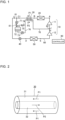
- Fig. 1 is a refrigerant circuit diagram illustrating the configuration of a refrigeration cycle apparatus according to Embodiment 1.
- the refrigeration cycle apparatus includes, as a main circuit, a refrigerant circuit in which a compressor 10, a condenser 20, an heat inter changer (HIC) 30, an expansion valve 40, and an evaporator 50 are connected by a refrigerant pipe 60.
- the compressor 10 includes a high-stage compressor 11 and a low-stage compressor 12.
- the refrigeration cycle apparatus is used as, for example, a refrigeration apparatus, but is not limited to this usage.
- the refrigeration cycle apparatus includes an injection circuit 70, as shown in Fig. 1 .
- the injection circuit 70 is an intermediate pressure refrigerant bypass circuit for causing refrigerant having an intermediate pressure P M , which will be described later, to flow.
- an INJ branch unit 61 is provided between the heat inter changer (HIC) 30 and the expansion valve 40.
- an INJ junction unit 62 is provided between a discharge side of the low-stage compressor 12 and a suction side of the high-stage compressor 11.
- One end of the injection circuit 70 is connected to the INJ branch unit 61 and the other end of the injection circuit 70 is connected to the INJ junction unit 62.
- the injection circuit 70 is formed by connecting an INJ expansion valve 71, a receiver 72, and a flow control valve 73 by an injection pipe 76. Furthermore, the injection circuit 70 may be provided with a gas vent pipe 74.
- the gas vent pipe 74 is a bypass pipe connected between the receiver 72 and the injection pipe 76.
- the gas vent pipe 74 may be provided with an on-off valve 75.
- refrigerant flows in the refrigerant pipe 60 through the low-stage compressor 12, the INJ junction unit 62, the high-stage compressor 11, the condenser 20, the heat inter changer (HIC) 30, the INJ branch unit 61, the expansion valve 40, and the evaporator 50 in this order.
- the low-stage compressor 12 the INJ junction unit 62
- the high-stage compressor 11 the condenser 20
- the heat inter changer (HIC) 30 the INJ branch unit 61
- the expansion valve 40 the evaporator 50 in this order.
- refrigerant flows in the injection pipe 76 through the INJ branch unit 61, the INJ expansion valve 71, the receiver 72, the flow control valve 73, the heat inter changer (HIC) 30, and the INJ junction unit 62 in this order.
- the low-stage compressor 12 is configured to compress sucked refrigerant to cause the pressure of the refrigerant to rise from a low pressure P L to an intermediate pressure P M , and discharge the refrigerant.
- the low-stage compressor 12 is, for example, an inverter compressor.
- the rotating speed may be changed to any speed by a driving circuit, such as an inverter circuit, to change the volume of refrigerant delivered by the low-stage compressor 12 per unit time.
- the driving circuit is controlled by a controller 90.
- the low pressure P L is a first pressure set in advance.
- the high-stage compressor 11 is configured to compress the refrigerant having the intermediate pressure P M discharged from the low-stage compressor 12 and the refrigerant having the intermediate pressure P M that flows in from the injection circuit 70 to cause the pressure of the refrigerant to rise to a high pressure P H .
- the refrigerant discharged from the high-stage compressor 11 flows into the condenser 20.
- the high-stage compressor 11 is, for example, an inverter compressor.
- the high-stage compressor 11 is an inverter compressor, the rotating speed may be changed to any speed by a driving circuit, such as an inverter circuit, to change the volume of refrigerant delivered by the high-stage compressor 11 per unit time.
- the driving circuit is controlled by the controller 90.
- the high pressure P H is a second pressure set in advance. The second pressure is higher than the first pressure.
- the intermediate pressure P M is higher than the first pressure and lower than the second pressure.
- the condenser 20 is provided outdoors, for example.
- the condenser 20 is a heat exchanger that performs heat exchange between refrigerant flowing in the heat exchanger and air.
- the condenser 20 is, for example, a fin-and-tube type heat exchanger.
- the refrigerant condensed and liquefied in the condenser 20 flows into the heat inter changer (HIC) 30.
- HIC heat inter changer
- the heat inter changer (HIC) 30 is configured to perform inter-refrigerant heat exchange to cool one refrigerant by the other refrigerant. As shown in Fig. 2 , the heat inter changer (HIC) 30 is formed by a double pipe. Fig. 2 is a perspective view illustrating an example of the configuration of the heat inter changer (HIC) 30 provided in the refrigeration cycle apparatus according to Embodiment 1. In Fig. 2 , part of the configuration is transparently represented by broken lines for the purpose of explanation. In the example of Fig. 2 , the heat inter changer (HIC) 30 includes an outer pipe 31 provided on an outer side and an inner pipe 32 provided inside the outer pipe 31.
- the refrigerant that flows out of the condenser 20 flows in the outer pipe 31 in the direction of arrows P1 of Fig. 2 .
- the refrigerant flowing in the injection pipe 76 flows in the inner pipe 32 in the direction of arrow P2 of Fig. 2 .
- the direction (direction of arrows P1) in which the refrigerant flows in the outer pipe 31 and the direction (direction of arrow P2) in which the refrigerant flows in the inner pipe 32 are opposite to each other, and the flows of the refrigerant face each other.
- the heat inter changer (HIC) 30 is not limited to the example of Fig. 2 .
- the refrigerant flowing in the injection pipe 76 may flow in the outer pipe 31, and the refrigerant that flows out of the condenser 20 may flow in the inner pipe 32.
- the heat inter changer (HIC) 30 may be of another configuration.
- the refrigerant (second refrigerant, which will be described later) that flows out of the receiver 72 and flows in the injection pipe 76 cools the refrigerant that flows out of the condenser 20 and applies subcooling to the refrigerant that flows out of the condenser 20.
- the refrigerant (second refrigerant) that has applied subcooling and has gasified continues to flow in the injection pipe 76, and is guided to the INJ junction unit 62.
- the INJ junction unit 62 is provided between the discharge side of the low-stage compressor 12 and the suction side of the high-stage compressor 11.
- the refrigerant on which subcooling has been applied in the heat inter changer (HIC) 30 is branched into first refrigerant and second refrigerant at the INJ branch unit 61.
- the first refrigerant branched at the INJ branch unit 61 flows in the refrigerant pipe 60 and is guided to the expansion valve 40.
- the expansion valve 40 is configured to expand the first refrigerant to reduce the pressure of the first refrigerant.
- the first refrigerant that is expanded and caused to have the low pressure P L flows into the evaporator 50.
- the expansion valve 40 is, for example, an electronic expansion valve. When the expansion valve 40 is formed by an electronic expansion valve, the opening degree is controlled by the controller 90 to be adjusted.
- the evaporator 50 is provided in an indoor space, for example.
- the evaporator 50 is a heat exchanger that performs heat exchange between the refrigerant flowing in the heat exchanger and air.
- the evaporator 50 is, for example, a fin-and-tube type heat exchanger. In the evaporator 50, heat exchange is performed between the first refrigerant and air, and the first refrigerant is evaporated. The first refrigerant that is evaporated and gasified is sucked into the low-stage compressor 12.
- the low-stage compressor 12 sucks the refrigerant having the low pressure P L that flows out of the evaporator 50, compresses the refrigerant to cause the pressure of the refrigerant to rise to the intermediate pressure P M , and discharges the refrigerant.
- the second refrigerant branched at the INJ branch unit 61 flows in the injection pipe 76 and flows into the INJ expansion valve 71 first.
- the INJ expansion valve 71 is configured to expand the second refrigerant and thus reduce the pressure of the second refrigerant.
- the second refrigerant expanded and caused to have the intermediate pressure P M flows into the receiver 72.
- the INJ expansion valve 71 is, for example, an electronic expansion valve.
- the opening degree is controlled by the controller 90 to be adjusted.
- the receiver 72 is configured to store the second refrigerant that is expanded by the INJ expansion valve 71 and caused to have the intermediate pressure P M .
- the second refrigerant is separated into the refrigerant in a liquid state and the refrigerant in a gas state.
- the refrigerant in a liquid state separated in the receiver 72 flows into the inner pipe 32 of the heat inter changer (HIC) 30 via the injection pipe 76.
- the second refrigerant flowing in the inner pipe 32 exchanges heat with the refrigerant flowing in the outer pipe 31, and then is guided to the INJ junction unit 62.
- the second refrigerant cools the refrigerant flowing in the outer pipe 31 and applies subcooling to the refrigerant flowing in the outer pipe 31.
- the injection pipe 76 between the receiver 72 and the heat inter changer (HIC) 30 is provided with the flow control valve 73.
- the flow rate of the second refrigerant flowing out of the receiver 72 is controlled according to the opening degree of the flow control valve 73.
- the flow control valve 73 is, for example, an electronic control valve. In this case, the opening degree of the flow control valve 73 is controlled by the controller 90.
- the flow control valve 73 is not necessarily required, and may be installed only when needed.
- the heat inter changer (HIC) 30 is not necessarily required, and may be installed only when needed.
- the second refrigerant having the intermediate pressure P M flowing in the injection pipe 76 and the first refrigerant having the intermediate pressure P M discharged by the low-stage compressor 12 are joined together.
- the refrigerant joined at the INJ junction unit 62 is sucked into the high-stage compressor 11.
- the high-stage compressor 11 compresses the sucked refrigerant from the intermediate pressure P M to the high pressure P H , and discharged the refrigerant.
- the gas vent pipe 74 is a bypass pipe connected between the receiver 72 and the injection pipe 76.
- One end of the gas vent pipe 74 is connected to an upper part of the receiver 72, and the other end of the gas vent pipe 74 is connected between the flow control valve 73 and the heat inter changer (HIC) 30.
- the on-off valve 75 When the on-off valve 75 is in an open state, the gas vent pipe 74 causes the refrigerant in a gas state in the receiver 72 to flow into the injection pipe 76.
- the on-off valve 75 is in a closed state, the gas vent pipe 74 stops the outflow of the refrigerant in a gas state in the receiver 72.
- the composition of the refrigerant flowing in the injection circuit 70 that is, the gas density of the refrigerant can be finely adjusted.
- the gas vent pipe 74 is not necessarily required, and may be installed only when needed.
- the controller 90 includes a processing circuit.
- the processing circuit is dedicated hardware or a processor.
- the dedicated hardware is, for example, an application specific integrated circuit (ASIC), a field-programmable gate array (FPGA), or a similar circuit.
- the processor is configured to execute a program stored in the memory.
- Storage circuitry (not shown) provided in the controller 90 is formed by a memory.
- the memory is, for example, a non-volatile or volatile semiconductor memory, such as a random access memory (RAM), a read only memory (ROM), a flash memory, and an erasable programmable ROM (EPROM), or a disk, such as a magnetic disk, a flexible disk, and an optical disk.
- a pressure sensor 81 configured to measure an intermediate pressure P M is provided between the INJ expansion valve 71 and the receiver 72 in Embodiment 1.
- An intermediate pressure P M detected by the pressure sensor 81 is transmitted to the controller 90.
- the intermediate pressure P M is an internal pressure of the receiver 72.
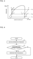
- Fig. 3 is a p-h diagram illustrating a refrigeration cycle of the refrigeration cycle apparatus according to Embodiment 1.
- the horizontal axis represents specific enthalpy
- the vertical axis represents pressure of the refrigerant.
- points A to J in Fig. 3 correspond to the points shown in the refrigerant circuit diagram of Fig. 1 .
- point C and point C1 are actually the same point, but are represented as slightly displaced points for the purpose of explanation.
- the high-stage compressor 11 sucks the refrigerant having the intermediate pressure P M (state of point J) and compresses the refrigerant to the high pressure P H (state of point A).
- the refrigerant in a high-temperature and high-pressure gas state (state of point A) discharged from the high-stage compressor 11 flows into the condenser 20.
- the refrigerant in a high-temperature and high-pressure gas state rejects heat to air, is thus condensed and liquefied, and then the refrigerant enters a liquid state having the high pressure P H (state of point B).
- the refrigerant in a high-pressure liquid state passes through the heat inter changer (HIC) 30 in a direction of arrow P1 of Fig. 1 , and enters a state in which the degree of subcooling is increased further (states of points C and C1).
- Part of the refrigerant (state of point C1) that has passed through the heat inter changer (HIC) 30 flows into the INJ expansion valve 71 via the INJ branch unit 61.
- the INJ expansion valve 71 the refrigerant in a liquid state having the high pressure P H is decompressed to the intermediate pressure P M . Then, the refrigerant flows into the receiver 72, and enters a two-phase gas-liquid state (state of point H).
- the refrigerant in a liquid state that flows out of the receiver 72 passes through the heat inter changer (HIC) 30 in a direction of arrow P2, which is opposite to the direction of arrow P1.
- the refrigerant enters a two-phase state having the intermediate pressure P M and an increased temperature (state of point I).
- the expansion valve 40 the refrigerant in a liquid state having the high pressure P H is decompressed to the low pressure P L , and enters a two-phase gas-liquid state (state of point D).
- the refrigerant in a two-phase state having the low pressure P L receives heat from air and is thus evaporated, and then enters a gas state having the low pressure P L (state of point E).
- the refrigerant in a gas state having the low pressure P L flows into the low-stage compressor 12.
- the low-stage compressor 12 sucks the refrigerant having the low pressure P L and compresses the refrigerant to the intermediate pressure P M (state of point F).
- the refrigerant in a gas state having the intermediate pressure P M (state of point F) discharged from the low-stage compressor 12 is joined to the refrigerant in a two-phase state having the intermediate pressure P M (state of point I) that flows out of the heat inter changer (HIC) 30 in the direction of arrow P2, and becomes the refrigerant having a quality of almost saturated vapor (state of point J).
- the refrigerant having this quality is sucked into the high-stage compressor 11, and the same cycle is repeated again.
- a zeotropic refrigerant for example, is used as the refrigerant.
- a CO 2 refrigerant mixture such as R463A, can be used particularly among zeotropic refrigerants.
- the composition of R463A includes 36 mass% R32, 30 mass% R125, 14 mass% R134a, 14 mass% R1234yf, and 6 mass% R744 (CO 2 ).
- the gas density in the receiver 72 varies according to the intermediate pressure P M . Consequently, the composition of the refrigerant flowing in the injection circuit 70 changes and, as a result, the composition of the circulating refrigerant circulating in the refrigerant pipe 60 changes. Especially when a CO 2 refrigerant mixture among zeotropic refrigerants is used, the magnitude of change in the composition of the circulating refrigerant is large.
- the intermediate pressure P M which is the internal pressure of the receiver 72, to stabilize the composition of the circulating refrigerant circulating in the refrigerant pipe 60. More specifically, the intermediate pressure P M is controlled by using a control method (M1) or (M2) described below.
- Control method (M1) control is exercised such that the intermediate pressure P M falls to or below a first threshold.
- Control method (M2) control is exercised such that the intermediate pressure P M is kept constant. As long as the intermediate pressure P M is kept constant and stabilized, variation in the gas density in the receiver 72 can be reduced, and thus the composition of the circulating refrigerant can be stabilized.
- Fig. 4 is a flowchart illustrating a flow of processing in the control method (M1).
- control is exercised such at the intermediate pressure P M falls to or below a first threshold.
- step S1 the controller 90 obtains a detection value of the intermediate pressure P M from the pressure sensor 81.
- step S2 the controller 90 compares the intermediate pressure P M to the first threshold.
- the comparison result indicates that the intermediate pressure P M is greater than the first threshold
- the process proceeds to step S3.
- the comparison result indicates that the intermediate pressure P M is less than or equal to the first threshold
- the processing of flow in Fig. 4 is terminated with no further processing.
- step S3 the controller 90 performs a predetermined first processing for the intermediate pressure P M such that the intermediate pressure P M falls to or below the first threshold. With this processing, the intermediate pressure P M is lowered.
- the first threshold is, for example, a geometric mean of the low pressure P L and the high pressure P H .
- the first threshold is calculated by the following formula (1).
- First threshold P L ⁇ P H 1 / 2
- the first threshold for the intermediate pressure P M which is the discharge pressure of the low-stage compressor 12
- the first threshold for the intermediate pressure P L which is the discharge pressure of the low-stage compressor 12
- the high pressure P H which is the pressure of the refrigerant discharged by the high-stage compressor 11.
- Examples of the first processing include processing (a1) and processing (b1) described below.
- the controller 90 is configured to perform at least one of the processing (a1) and processing (b1) as the "first processing".
- the controller 90 is configured to increase a ratio of displacement of the high-stage compressor 11 to displacement of the low-stage compressor 12. That is, the controller 90 increases the ratio of displacement of the high-stage compressor 11 to displacement of the low-stage compressor 12.
- the displacement of the low-stage compressor 12 and the displacement of the high-stage compressor 11 are calculated by the following formula (2). That is, not only the rotating speed ratio of the low-stage compressor 12 and the high-stage compressor 11 but also the volume ratio of the low-stage compressor 12 and the high-stage compressor 11 is taken into account.
- Displacement of low ⁇ stage compressor volume of low ⁇ stage compressor ⁇ rotating speed of low ⁇ stage compressor
- Displacement of high ⁇ stage compressor volume of high ⁇ stage compressor ⁇ rotating speed of high ⁇ stage compressor
- the controller 90 can increase the ratio of displacement by a predetermined fixed amount, the controller 90 may increase the ratio of displacement by an amount corresponding to the value of the intermediate pressure P M .
- the storage circuitry of the controller 90 stores in advance a data table in which values of the intermediate pressure P M and increased amounts of ratio of displacement are stored in association with each other.
- the controller 90 actually increases a ratio of rotating speed of the high-stage compressor 11 to rotating speed of the low-stage compressor 12.
- the controller 90 controls at least one of the rotating speed of the low-stage compressor 12 and the rotating speed of the high-stage compressor 11.
- the first processing in a case of the processing (b1) will be described.
- the controller 90 is configured to reduce the opening degree of the INJ expansion valve 71.
- the controller 90 can reduce the opening degree of the INJ expansion valve 71 by a predetermined fixed amount
- the controller 90 may reduce the opening degree of the INJ expansion valve 71 by an amount corresponding to the value of the intermediate pressure P M .
- the storage circuitry of the controller 90 stores in advance a data table in which values of the intermediate pressure P M and reduced amounts of opening degree of the INJ expansion valve 71 are stored in association with each other.
- the controller 90 performs the predetermined first processing in step S3. With this processing, the intermediate pressure P M is lowered.
- the controller 90 is configured to perform the processing of the flow of Fig. 4 repeatedly at fixed intervals.
- the intermediate pressure P M can be controlled to fall to or below the first threshold.
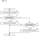
- Fig. 5 is a flowchart illustrating a flow of processing in the control method (M2).
- the controller 90 is configured to exercise control to keep the intermediate pressure P M constant (that is, at a constant value).
- the constant value is set to have a certain range. That is, a description is made for a case where the intermediate pressure P M is controlled such that the intermediate pressure P M is kept within a first range including the constant value.
- the "constant" is defined as a state of being constant within a predetermined first range, or a state of being substantially constant with slight fluctuation.
- the first range is described as a range that is greater than a predetermined second threshold and less than or equal to the first threshold.
- step S1 the controller 90 obtains a detection value of the intermediate pressure P M from the pressure sensor 81.
- step S2 the controller 90 compares the intermediate pressure P M to the first threshold.
- the comparison result indicates that the intermediate pressure P M is greater than the first threshold
- the process proceeds to step S3.
- the comparison result indicates that the intermediate pressure P M is less than or equal to the first threshold.
- step S3 the controller 90 performs the predetermined first processing for the intermediate pressure P M such that the intermediate pressure P M falls to or below the first threshold. With this processing, the intermediate pressure P M is lowered. Because the first processing is described above, its description is omitted here.
- step S4 the controller 90 compares the intermediate pressure P M to the second threshold.
- the comparison result indicates that the intermediate pressure P M is greater than the second threshold
- the processing of flow in Fig. 5 is terminated with no further processing. Meanwhile, when the comparison result indicates that the intermediate pressure P M is less than or equal to the second threshold, the process proceeds to step S5.
- step S5 the controller 90 performs the predetermined second processing for the intermediate pressure P M such that the intermediate pressure P M becomes higher than the second threshold. Thus, the intermediate pressure P M is raised.
- the second threshold is, for example, a value in which a negative tolerance ⁇ is provided to the first threshold. That is, the second threshold is smaller than the first threshold by a value of ⁇ .
- ⁇ is a predetermined positive real number.
- the second threshold is calculated by the following formula (3). Note that, as the value of ⁇ decreases, a fluctuation range of the intermediate pressure P M decreases. Therefore, the value of ⁇ is determined, as appropriate, on the basis of an allowable fluctuation range for the intermediate pressure P M to be controlled constant.
- Second threshold first threshold ⁇ ⁇
- Examples of the second processing include processing (a2) and processing (b2) described below.
- the controller 90 is configured to perform at least one of the processing (a2) and processing (b2) as the "second processing".
- the controller 90 is configured to reduce a ratio of displacement of the high-stage compressor 11 to displacement of the low-stage compressor 12. That is, the controller 90 reduces the ratio of displacement of the high-stage compressor 11 to displacement of the low-stage compressor 12.
- the displacement of the low-stage compressor 12 and the displacement of the high-stage compressor 11 are calculated by the formula (2) described above.
- the controller 90 can reduce the ratio of displacement by a predetermined fixed amount, the controller 90 may reduce the ratio of displacement by an amount corresponding to the value of the intermediate pressure P M .
- the storage circuitry of the controller 90 stores in advance a data table in which values of the intermediate pressure P M and reduced amounts of ratio of displacement are stored in association with each other.
- a ratio of rotating speed of the high-stage compressor 11 to rotating speed of the low-stage compressor 12 is reduced. More specifically, the controller 90 controls at least one of the rotating speed of the low-stage compressor 12 and the rotating speed of the high-stage compressor 11.
- the second processing in a case of the processing (b2) will be described.
- the controller 90 is configured to increase the opening degree of the INJ expansion valve 71.
- the controller 90 can increase the opening degree of the INJ expansion valve 71 by a predetermined fixed amount
- the controller 90 may increase the opening degree of the INJ expansion valve 71 by an amount corresponding to the value of the intermediate pressure P M .
- the storage circuitry of the controller 90 stores in advance a data table in which values of the intermediate pressure P M and increased amounts of opening degree of the INJ expansion valve 71 are stored in association with each other.
- the controller 90 performs the predetermined second processing in step S5. With this processing, the intermediate pressure P M is raised.
- the controller 90 is configured to perform the processing of the flow of Fig. 5 repeatedly at fixed intervals.
- the intermediate pressure P M can be controlled such that the intermediate pressure P M is kept constant or substantially constant within the first range. That is, the intermediate pressure P M can be controlled such that a relationship of first threshold ⁇ intermediate pressure P M > second threshold is constantly satisfied.
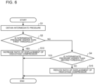
- Fig. 6 is a flowchart illustrating a flow of processing when processing (a1) and processing (a2) are performed as the first processing and the second processing in the flow of Fig. 5 .
- the controller 90 controls the intermediate pressure P M by controlling the ratio of displacement of the high-stage compressor 11 to displacement of the low-stage compressor 12.
- step S13 the processing of step S13 is performed in place of step S3 of Fig. 5 .
- the controller 90 increases the ratio of displacement of the high-stage compressor 11 to displacement of the low-stage compressor 12. As a result, the intermediate pressure P M is lowered.
- step S15 the processing of step S15 is performed in place of step S5 of Fig. 5 .
- the controller 90 reduces the ratio of displacement of the high-stage compressor 11 to displacement of the low-stage compressor 12. As a result, the intermediate pressure P M is raised.
- Fig. 7 is a flowchart illustrating a flow of processing when processing (b1) and processing (b2) are performed as the first processing and the second processing in the flow of Fig. 5 .
- the controller 90 controls the intermediate pressure P M by controlling the opening degree of the INJ expansion valve 71.
- step S23 the processing of step S23 is performed in place of step S3 of Fig. 5 .
- the controller 90 reduces the opening degree of the INJ expansion valve 71. As a result, the intermediate pressure P M is lowered.
- step S25 the processing of step S25 is performed in place of step S5 of Fig. 5 .
- the controller 90 increases the opening degree of the INJ expansion valve 71. As a result, the intermediate pressure P M is raised.
- Fig. 8 is a refrigerant circuit diagram illustrating the configuration of a modified example of the refrigeration cycle apparatus according to Embodiment 1.
- Fig. 8 differs from Fig. 1 in that the compressor 10 in Fig. 8 is formed by an injection compressor 13.
- the compressor 10 may be formed by the injection compressor 13, which is a single-stage compressor provided with an intermediate pressure INJ port.
- the intermediate pressure P M is controlled by controlling the opening degree of the INJ expansion valve 71 by using the control method (M2) described above.
- M2 control method
- Fig. 9 is an explanatory diagram schematically illustrating the configuration of the low-stage compressor 12 and the high-stage compressor of Fig. 1 .
- Fig. 10 is an explanatory diagram schematically illustrating the configuration of the injection compressor 13 of Fig. 8 .
- Fig. 9 shows the configuration of a general rotary compressor.
- the high-stage compressor 11 and the low-stage compressor 12 of Fig. 1 each have the configuration shown in Fig. 9 .
- the compressor has a suction port 10a from which refrigerant is sucked and a discharge port 10b from which refrigerant is discharged.
- a compression mechanism 10c which compresses refrigerant
- a driving mechanism 10d which drives the compression mechanism 10c
- the compression mechanism 10c has a compression chamber 10c-1 in which refrigerant is compressed.
- the driving mechanism 10d is formed by, for example, a driving motor that drives the compression mechanism 10c.
- an accumulator 10e may be provided on the suction port 10a side.
- Fig. 10 shows the configuration of an injection rotary compressor forming the injection compressor 13.
- an intermediate pressure INJ port 10f which is an injection refrigerant suction port, is added to the configuration of Fig. 9 .
- the refrigerant having the intermediate pressure Pnn flowing in the injection circuit 70 is sucked into the intermediate pressure INJ port 10f.
- the refrigerant is caused to flow into the compression chamber 10c-1 provided in the compression mechanism 10c.
- the refrigerant having the low pressure P L flowing from the evaporator 50 is sucked into the suction port 10a of the injection compressor 13.
- the refrigerant that flows out of the evaporator 50 and the refrigerant that flows in from the injection circuit 70 are mixed and compressed to the high pressure P H .
- an injection pipe 10h connected to the intermediate pressure INJ port 10f may be provided with an injection muffler 10g.
- the injection muffler 10g is configured to prevent the refrigerant from flowing backward from the compression chamber 10c-1 to the intermediate pressure INJ port 10f.
- mesh installed inside the injection muffler 10g, a foreign object can be captured by the mesh, and thus reliability can be further enhanced.
- the compressor is not limited to this case.
- the low-stage compressor 12 and the high-stage compressor 11 each may be formed by a scroll compressor or a screw compressor.
- the injection compressor 13 may be formed by a scroll compressor, or a screw compressor, provided with the intermediate pressure INJ port 10f.
- the compressor 10 may be formed by the high-stage compressor 11 and the low-stage compressor 12 as shown in Fig. 1 , or may be formed by the injection compressor 13 as shown in Fig. 8 . In either case, the same effect can be obtained.
- the refrigeration cycle apparatus includes the injection circuit 70 having the INJ expansion valve 71 and the receiver 72. Furthermore, the controller 90 is configured to control at least one of the operation of the compressor 10 and the opening degree of the INJ expansion valve 71 such that the intermediate pressure P M , which is the internal pressure of the receiver 72, falls to or below the first threshold. Alternatively, the controller 90 is configured to control the intermediate pressure P M to fall within the first range. With this control, the gas density of the refrigerant staying in the receiver 72 is reduced, and thus change in the composition of the circulating refrigerant from the original composition is reduced. As a result, the composition of the circulating refrigerant is stabilized, and therefore change from the original composition can be minimized as possible. When the composition of the circulating refrigerant is stabilized, variation in the refrigeration capacity of the refrigeration cycle apparatus is reduced or eliminated, and insufficient cooling of an indoor space by the evaporator 50 can be prevented.
- Embodiment 1 when the intermediate pressure P M is controlled by operation of the compressor, the control is exercised by controlling the ratio of displacement of the high-stage compressor 11 to displacement of the low-stage compressor 12.
- the control is exercised by controlling the ratio of rotating speed of the high-stage compressor 11 to rotating speed of the low-stage compressor 12
- the volume ratio of the low-stage compressor 12 and the high-stage compressor 11 is not taken into account.
- the control because the control is exercised by using the ratio of displacement, the rotating speed ratio is controlled while the volume ratio of the low-stage compressor 12 and the high-stage compressor 11 is taken into account. Therefore, the intermediate pressure P M can be controlled with higher accuracy in Embodiment 1.
- the refrigeration cycle apparatus according to Embodiment 1 is especially effective when a CO 2 refrigerant mixture is used.
- the refrigeration cycle apparatus according to Embodiment 1 is provided with the heat inter changer (HIC) 30, subcooling can be increased, and the performance of the refrigeration cycle apparatus can be further improved.
- HIC heat inter changer
- 10 compressor, 10a: suction port, 10b: discharge port, 10c: compression mechanism, 10c-1: compression chamber, 10d: driving mechanism, 10e: accumulator, 10f: intermediate pressure INJ port, 10g: injection muffler, 11: high-stage compressor, 12: low-stage compressor, 13: injection compressor, 20: condenser, 31: outer pipe, 32: inner pipe, 40: expansion valve, 50: evaporator, 60: refrigerant pipe, 61: INJ branch unit, 62: INJ junction unit, 70: injection circuit, 71: INJ expansion valve, 72: receiver, 73: flow control valve, 74: gas vent pipe, 75: on-off valve, 76: injection pipe, 81: pressure sensor, 90: controller, P1: arrow, P2: arrow, P H : high pressure (second pressure), P L : low pressure (first pressure), P M : intermediate pressure
Landscapes
- Engineering & Computer Science (AREA)
- Physics & Mathematics (AREA)
- Mechanical Engineering (AREA)
- Thermal Sciences (AREA)
- General Engineering & Computer Science (AREA)
- Applications Or Details Of Rotary Compressors (AREA)
- Compression-Type Refrigeration Machines With Reversible Cycles (AREA)
Abstract
Description
- The present disclosure relates to a refrigeration cycle apparatus having an intermediate pressure receiver.
- A multistage compression refrigeration cycle apparatus including a low-stage compressor and a high-stage compressor that performs two-stage compression not to excessively reduce the pressure in an outdoor heat exchanger even when the outside air temperature is low is known (see, for example, Patent Literature 1).
- In the refrigeration cycle apparatus described in
Patent Literature 1, a low-stage compressor, a high-stage compressor, a use-side heat exchanger, a use-side expansion valve, a receiver, a subcooling heat exchanger, an expansion valve, and an outdoor heat exchanger are connected by refrigerant pipes. - The low-stage compressor compresses sucked refrigerant from a low pressure to an intermediate pressure. The high-stage compressor compresses the refrigerant having an intermediate pressure discharged from the low-stage compressor to a high pressure. The refrigerant discharged from the high-stage compressor flows into the use-side heat exchanger. The refrigerant condensed and liquefied in the use-side heat exchanger passes through the use-side expansion valve, thereby being decompressed. The decompressed refrigerant flows into the receiver.
- In the receiver, the refrigerant in a gas state and the refrigerant in a liquid state are separated from each other. The refrigerant in a liquid state separated in the receiver is divided at a branch point. Part of the refrigerant in a liquid state (hereinafter referred to as first refrigerant) is guided to the subcooling heat exchanger provided on the downstream side of the branch point. Meanwhile, the remaining part of the refrigerant in a liquid state (hereinafter referred to as second refrigerant) is expanded by the subcooling expansion valve and then guided to the subcooling heat exchanger. In the subcooling heat exchanger, the second refrigerant cools the first refrigerant and applies subcooling to the first refrigerant. The second refrigerant that has applied subcooling to the first refrigerant and has been gasified is guided between the discharge side of the low-stage compressor and the suction side of the high-stage compressor via an intermediate pressure injection line.
- Meanwhile, the first refrigerant on which subcooling has been applied is guided to the expansion valve. The first refrigerant expanded by the expansion valve enters a low-pressure state and flows into the outdoor heat exchanger. In the outdoor heat exchanger, heat is exchanged between the first refrigerant and the outside air, and the first refrigerant is thereby evaporated. The first refrigerant that is evaporated and gasified in the outdoor heat exchanger is sucked into the low-stage compressor.
- Patent Literature 1:
Japanese Unexamined Patent Application Publication No. 2018-21732 - There are two types of refrigerant, a simple composition refrigerant and a refrigerant mixture in which a plurality of refrigerants are mixed. When a plurality of refrigerant components are mixed in a certain ratio, a refrigerant mixture that has a constant boiling point, has the same composition in the gas phase and the liquid phase, and changes its phase as if the refrigerant mixture is a single component may be obtained. Such a refrigerant mixture is called "azeotropic refrigerant mixture".
- On the other hand, a refrigerant mixture that acts just like a mixture of refrigerants having different dew points and different boiling points in the whole composition range is called "zeotropic refrigerant mixture". When a zeotropic refrigerant mixture is used in a refrigeration cycle apparatus, the composition varies constantly. Especially when leakage of the refrigerant occurs, the composition changes from the composition of the original mixture ratio. Examples of the zeotropic refrigerant mixture include R404A, R407C, and R463A. R463A is a carbon dioxide (CO2) refrigerant mixture in which CO2 is mixed. Among the zeotropic refrigerant mixtures, a CO2 refrigerant mixture, in particular, causes a significant composition change.
-
Patent Literature 1 indicates that R134a or R1234yf is used as refrigerant but does not indicate an intention to use a zeotropic refrigerant mixture. - However, in the refrigeration cycle apparatus that has the receiver connected to the intermediate pressure injection line as described in
Patent Literature 1, when a zeotropic refrigerant is used, the gas density in the receiver varies according to the intermediate pressure. That is, because the pressure in the receiver is an intermediate pressure, when the intermediate pressure increases, the gas density in the receiver increases and the mass of the refrigerant in a gas state increases. Meanwhile, when the intermediate pressure decreases, the gas density in the receiver decreases and the mass of the refrigerant in a gas state decreases. In this case, given that the receiver has a fixed volume, the mass of the refrigerant in a liquid state varies according to the mass of the refrigerant in a gas state, and consequently the composition of circulating refrigerant, which is the refrigerant circulating in the refrigerant circuit, is changed. - Because the refrigerant in a liquid state circulates in the refrigerant circuit, when such variation in the gas density occurs in the receiver, the composition of the circulating refrigerant changes and variation in the capacity of the refrigeration cycle apparatus occurs. As a result, in some cases, there is a possibility that insufficiency of cooling occurs in an evaporator of the refrigeration cycle apparatus.
- The present disclosure has been made to solve the problem described above, and has an object to obtain a refrigeration cycle apparatus capable of reducing or eliminating variation in the intermediate pressure in the receiver, reducing or eliminating variation in the composition of the circulating refrigerant, and preventing insufficient cooling from occurring in the refrigeration cycle apparatus.
- A refrigeration cycle apparatus according to an embodiment of the present disclosure includes a controller, a compressor configured to compress refrigerant to cause a pressure of the refrigerant to rise from a first pressure to a second pressure higher than the first pressure, a condenser configured to cause heat exchange to be performed between air and the refrigerant discharged from the compressor, an INJ branch unit configured to cause the refrigerant that flows out of the condenser to branch into first refrigerant and second refrigerant, an expansion valve configured to expand the first refrigerant that flows out of the INJ branch unit to reduce a pressure of the first refrigerant to the first pressure, an evaporator configured to cause heat exchange to be performed between air and the first refrigerant that flows out of the expansion valve, and cause the first refrigerant having the first pressure to flow to the compressor, and an injection circuit connected between the INJ branch unit and the compressor, and configured to cause the second refrigerant that flows out of the INJ branch unit to flow to the compressor. The injection circuit includes an INJ expansion valve configured to expand the second refrigerant to reduce a pressure of the second refrigerant to an intermediate pressure that is higher than the first pressure and lower than the second pressure, and a receiver configured to store the second refrigerant that flows out of the INJ expansion valve, and cause the second refrigerant having the intermediate pressure to flow to the compressor. The controller is configured to control at least one of a rotating speed of the compressor and an opening degree of the INJ expansion valve such that the intermediate pressure, which corresponds to an internal pressure of the receiver, falls to or below a first threshold or is kept constant within a first range. Advantageous Effects of Invention
- With the refrigeration cycle apparatus according to an embodiment of the present disclosure, variation in the intermediate pressure in the receiver is reduced or eliminated, variation in the composition of circulating refrigerant is reduced or eliminated, and thus insufficient cooling can be prevented from occurring in the refrigeration cycle apparatus.
-
- [
Fig. 1] Fig. 1 is a refrigerant circuit diagram illustrating the configuration of a refrigeration cycle apparatus according toEmbodiment 1. - [
Fig. 2] Fig. 2 is a perspective view illustrating an example of the configuration of a heat inter changer (HIC) 30 provided in the refrigeration cycle apparatus according toEmbodiment 1. - [
Fig. 3] Fig. 3 is a pressure-enthalpy (p-h) diagram illustrating a refrigeration cycle of the refrigeration cycle apparatus according toEmbodiment 1. - [
Fig. 4] Fig. 4 is a flowchart illustrating a flow of processing in a control method (M1). - [
Fig. 5] Fig. 5 is a flowchart illustrating a flow of processing in a control method (M2). - [
Fig. 6] Fig. 6 is a flowchart illustrating a flow of processing when processing (a1) and processing (a2) are performed as a first processing and a second processing in the flow ofFig. 5 . - [
Fig. 7] Fig. 7 is a flowchart illustrating a flow of processing when processing (b1) and processing (b2) are performed as the first processing and the second processing in the flow ofFig. 5 . - [
Fig. 8] Fig. 8 is a refrigerant circuit diagram illustrating the configuration of a modified example of the refrigeration cycle apparatus according toEmbodiment 1. - [
Fig. 9] Fig. 9 is an explanatory diagram schematically illustrating the configuration of a low-stage compressor 12 and a high-stage compressor 11 ofFig. 1 . - [
Fig. 10] Fig. 10 is an explanatory diagram schematically illustrating the configuration of aninjection compressor 13 ofFig. 8 . - An embodiment of the refrigeration cycle apparatus according to the present disclosure is described below with reference to the drawings. The present disclosure is not limited to the embodiment below, and various modifications can be made without departing from the scope of the present disclosure. Furthermore, the present disclosure includes any combination of features that can be combined with each other among the features shown in the embodiment and its modified example described below. Moreover, in the drawings, components denoted by the same reference signs are the same or corresponding components, and this applies to the entire description. In addition, in the drawings, the relationship of relative sizes of components or the shape of each component may differ from actual one.
-
Fig. 1 is a refrigerant circuit diagram illustrating the configuration of a refrigeration cycle apparatus according toEmbodiment 1. As shown inFig. 1 , the refrigeration cycle apparatus includes, as a main circuit, a refrigerant circuit in which acompressor 10, acondenser 20, an heat inter changer (HIC) 30, anexpansion valve 40, and anevaporator 50 are connected by arefrigerant pipe 60. Thecompressor 10 includes a high-stage compressor 11 and a low-stage compressor 12. The refrigeration cycle apparatus is used as, for example, a refrigeration apparatus, but is not limited to this usage. - In addition, the refrigeration cycle apparatus includes an
injection circuit 70, as shown inFig. 1 . Theinjection circuit 70 is an intermediate pressure refrigerant bypass circuit for causing refrigerant having an intermediate pressure PM, which will be described later, to flow. Furthermore, as shown inFig. 1 , anINJ branch unit 61 is provided between the heat inter changer (HIC) 30 and theexpansion valve 40. In addition, anINJ junction unit 62 is provided between a discharge side of the low-stage compressor 12 and a suction side of the high-stage compressor 11. One end of theinjection circuit 70 is connected to theINJ branch unit 61 and the other end of theinjection circuit 70 is connected to theINJ junction unit 62. - The
injection circuit 70 is formed by connecting anINJ expansion valve 71, areceiver 72, and aflow control valve 73 by aninjection pipe 76. Furthermore, theinjection circuit 70 may be provided with agas vent pipe 74. Thegas vent pipe 74 is a bypass pipe connected between thereceiver 72 and theinjection pipe 76. Thegas vent pipe 74 may be provided with an on-offvalve 75. - In the main circuit, refrigerant flows in the
refrigerant pipe 60 through the low-stage compressor 12, theINJ junction unit 62, the high-stage compressor 11, thecondenser 20, the heat inter changer (HIC) 30, theINJ branch unit 61, theexpansion valve 40, and theevaporator 50 in this order. - Furthermore, in the
injection circuit 70, refrigerant flows in theinjection pipe 76 through theINJ branch unit 61, theINJ expansion valve 71, thereceiver 72, theflow control valve 73, the heat inter changer (HIC) 30, and theINJ junction unit 62 in this order. - Configurations of the devices forming the refrigeration cycle apparatus shown in
Fig. 1 will be described below. - The low-
stage compressor 12 is configured to compress sucked refrigerant to cause the pressure of the refrigerant to rise from a low pressure PL to an intermediate pressure PM, and discharge the refrigerant. The low-stage compressor 12 is, for example, an inverter compressor. When the low-stage compressor 12 is an inverter compressor, the rotating speed may be changed to any speed by a driving circuit, such as an inverter circuit, to change the volume of refrigerant delivered by the low-stage compressor 12 per unit time. In this case, the driving circuit is controlled by acontroller 90. Note that, the low pressure PL is a first pressure set in advance. - The high-stage compressor 11 is configured to compress the refrigerant having the intermediate pressure PM discharged from the low-
stage compressor 12 and the refrigerant having the intermediate pressure PM that flows in from theinjection circuit 70 to cause the pressure of the refrigerant to rise to a high pressure PH. The refrigerant discharged from the high-stage compressor 11 flows into thecondenser 20. The high-stage compressor 11 is, for example, an inverter compressor. When the high-stage compressor 11 is an inverter compressor, the rotating speed may be changed to any speed by a driving circuit, such as an inverter circuit, to change the volume of refrigerant delivered by the high-stage compressor 11 per unit time. In this case, the driving circuit is controlled by thecontroller 90. Note that, the high pressure PH is a second pressure set in advance. The second pressure is higher than the first pressure. In addition, the intermediate pressure PM is higher than the first pressure and lower than the second pressure. - The
condenser 20 is provided outdoors, for example. Thecondenser 20 is a heat exchanger that performs heat exchange between refrigerant flowing in the heat exchanger and air. Thecondenser 20 is, for example, a fin-and-tube type heat exchanger. The refrigerant condensed and liquefied in thecondenser 20 flows into the heat inter changer (HIC) 30. - The heat inter changer (HIC) 30 is configured to perform inter-refrigerant heat exchange to cool one refrigerant by the other refrigerant. As shown in
Fig. 2 , the heat inter changer (HIC) 30 is formed by a double pipe.Fig. 2 is a perspective view illustrating an example of the configuration of the heat inter changer (HIC) 30 provided in the refrigeration cycle apparatus according toEmbodiment 1. InFig. 2 , part of the configuration is transparently represented by broken lines for the purpose of explanation. In the example ofFig. 2 , the heat inter changer (HIC) 30 includes anouter pipe 31 provided on an outer side and aninner pipe 32 provided inside theouter pipe 31. The refrigerant that flows out of thecondenser 20 flows in theouter pipe 31 in the direction of arrows P1 ofFig. 2 . The refrigerant flowing in theinjection pipe 76 flows in theinner pipe 32 in the direction of arrow P2 ofFig. 2 . As shown by the arrows inFig. 2 , the direction (direction of arrows P1) in which the refrigerant flows in theouter pipe 31 and the direction (direction of arrow P2) in which the refrigerant flows in theinner pipe 32 are opposite to each other, and the flows of the refrigerant face each other. Note that, the heat inter changer (HIC) 30 is not limited to the example ofFig. 2 . For example, the refrigerant flowing in theinjection pipe 76 may flow in theouter pipe 31, and the refrigerant that flows out of thecondenser 20 may flow in theinner pipe 32. In addition, the heat inter changer (HIC) 30 may be of another configuration. - In the heat inter changer (HIC) 30, the refrigerant (second refrigerant, which will be described later) that flows out of the
receiver 72 and flows in theinjection pipe 76 cools the refrigerant that flows out of thecondenser 20 and applies subcooling to the refrigerant that flows out of thecondenser 20. The refrigerant (second refrigerant) that has applied subcooling and has gasified continues to flow in theinjection pipe 76, and is guided to theINJ junction unit 62. As described above, theINJ junction unit 62 is provided between the discharge side of the low-stage compressor 12 and the suction side of the high-stage compressor 11. - Meanwhile, the refrigerant on which subcooling has been applied in the heat inter changer (HIC) 30 is branched into first refrigerant and second refrigerant at the
INJ branch unit 61. The first refrigerant branched at theINJ branch unit 61 flows in therefrigerant pipe 60 and is guided to theexpansion valve 40. Theexpansion valve 40 is configured to expand the first refrigerant to reduce the pressure of the first refrigerant. The first refrigerant that is expanded and caused to have the low pressure PL flows into theevaporator 50. Theexpansion valve 40 is, for example, an electronic expansion valve. When theexpansion valve 40 is formed by an electronic expansion valve, the opening degree is controlled by thecontroller 90 to be adjusted. - The
evaporator 50 is provided in an indoor space, for example. Theevaporator 50 is a heat exchanger that performs heat exchange between the refrigerant flowing in the heat exchanger and air. Theevaporator 50 is, for example, a fin-and-tube type heat exchanger. In theevaporator 50, heat exchange is performed between the first refrigerant and air, and the first refrigerant is evaporated. The first refrigerant that is evaporated and gasified is sucked into the low-stage compressor 12. The low-stage compressor 12 sucks the refrigerant having the low pressure PL that flows out of theevaporator 50, compresses the refrigerant to cause the pressure of the refrigerant to rise to the intermediate pressure PM, and discharges the refrigerant. - Meanwhile, the second refrigerant branched at the
INJ branch unit 61 flows in theinjection pipe 76 and flows into theINJ expansion valve 71 first. - The
INJ expansion valve 71 is configured to expand the second refrigerant and thus reduce the pressure of the second refrigerant. The second refrigerant expanded and caused to have the intermediate pressure PM flows into thereceiver 72. TheINJ expansion valve 71 is, for example, an electronic expansion valve. When theINJ expansion valve 71 is formed by an electronic expansion valve, the opening degree is controlled by thecontroller 90 to be adjusted. - The
receiver 72 is configured to store the second refrigerant that is expanded by theINJ expansion valve 71 and caused to have the intermediate pressure PM. In thereceiver 72, the second refrigerant is separated into the refrigerant in a liquid state and the refrigerant in a gas state. The refrigerant in a liquid state separated in thereceiver 72 flows into theinner pipe 32 of the heat inter changer (HIC) 30 via theinjection pipe 76. The second refrigerant flowing in theinner pipe 32 exchanges heat with the refrigerant flowing in theouter pipe 31, and then is guided to theINJ junction unit 62. - At this time, in the heat inter changer (HIC) 30, the second refrigerant cools the refrigerant flowing in the
outer pipe 31 and applies subcooling to the refrigerant flowing in theouter pipe 31. - The
injection pipe 76 between thereceiver 72 and the heat inter changer (HIC) 30 is provided with theflow control valve 73. The flow rate of the second refrigerant flowing out of thereceiver 72 is controlled according to the opening degree of theflow control valve 73. Theflow control valve 73 is, for example, an electronic control valve. In this case, the opening degree of theflow control valve 73 is controlled by thecontroller 90. However, theflow control valve 73 is not necessarily required, and may be installed only when needed. In addition, the heat inter changer (HIC) 30 is not necessarily required, and may be installed only when needed. - In the
INJ junction unit 62, the second refrigerant having the intermediate pressure PM flowing in theinjection pipe 76 and the first refrigerant having the intermediate pressure PM discharged by the low-stage compressor 12 are joined together. The refrigerant joined at theINJ junction unit 62 is sucked into the high-stage compressor 11. The high-stage compressor 11 compresses the sucked refrigerant from the intermediate pressure PM to the high pressure PH, and discharged the refrigerant. - The
gas vent pipe 74 is a bypass pipe connected between thereceiver 72 and theinjection pipe 76. One end of thegas vent pipe 74 is connected to an upper part of thereceiver 72, and the other end of thegas vent pipe 74 is connected between theflow control valve 73 and the heat inter changer (HIC) 30. When the on-offvalve 75 is in an open state, thegas vent pipe 74 causes the refrigerant in a gas state in thereceiver 72 to flow into theinjection pipe 76. When the on-offvalve 75 is in a closed state, thegas vent pipe 74 stops the outflow of the refrigerant in a gas state in thereceiver 72. With this configuration, the composition of the refrigerant flowing in theinjection circuit 70, that is, the gas density of the refrigerant can be finely adjusted. Note, however, that thegas vent pipe 74 is not necessarily required, and may be installed only when needed. - The
controller 90 includes a processing circuit. The processing circuit is dedicated hardware or a processor. The dedicated hardware is, for example, an application specific integrated circuit (ASIC), a field-programmable gate array (FPGA), or a similar circuit. The processor is configured to execute a program stored in the memory. Storage circuitry (not shown) provided in thecontroller 90 is formed by a memory. The memory is, for example, a non-volatile or volatile semiconductor memory, such as a random access memory (RAM), a read only memory (ROM), a flash memory, and an erasable programmable ROM (EPROM), or a disk, such as a magnetic disk, a flexible disk, and an optical disk. - Furthermore, as shown in
Fig. 1 , apressure sensor 81 configured to measure an intermediate pressure PM is provided between theINJ expansion valve 71 and thereceiver 72 inEmbodiment 1. An intermediate pressure PM detected by thepressure sensor 81 is transmitted to thecontroller 90. The intermediate pressure PM is an internal pressure of thereceiver 72. -
Fig. 3 is a p-h diagram illustrating a refrigeration cycle of the refrigeration cycle apparatus according toEmbodiment 1. InFig. 3 , the horizontal axis represents specific enthalpy, and the vertical axis represents pressure of the refrigerant. Note that, points A to J inFig. 3 correspond to the points shown in the refrigerant circuit diagram ofFig. 1 . In addition, point C and point C1 are actually the same point, but are represented as slightly displaced points for the purpose of explanation. - First, the high-stage compressor 11 sucks the refrigerant having the intermediate pressure PM (state of point J) and compresses the refrigerant to the high pressure PH (state of point A). The refrigerant in a high-temperature and high-pressure gas state (state of point A) discharged from the high-stage compressor 11 flows into the
condenser 20. In thecondenser 20, the refrigerant in a high-temperature and high-pressure gas state rejects heat to air, is thus condensed and liquefied, and then the refrigerant enters a liquid state having the high pressure PH (state of point B). The refrigerant in a high-pressure liquid state passes through the heat inter changer (HIC) 30 in a direction of arrow P1 ofFig. 1 , and enters a state in which the degree of subcooling is increased further (states of points C and C1). Part of the refrigerant (state of point C1) that has passed through the heat inter changer (HIC) 30 flows into theINJ expansion valve 71 via theINJ branch unit 61. In theINJ expansion valve 71, the refrigerant in a liquid state having the high pressure PH is decompressed to the intermediate pressure PM. Then, the refrigerant flows into thereceiver 72, and enters a two-phase gas-liquid state (state of point H). Then, the refrigerant in a liquid state that flows out of thereceiver 72 passes through the heat inter changer (HIC) 30 in a direction of arrow P2, which is opposite to the direction of arrow P1. As a result, the refrigerant enters a two-phase state having the intermediate pressure PM and an increased temperature (state of point I). - Meanwhile, the remaining part of the refrigerant (state of point C) that has passed through the heat inter changer (HIC) 30 flows into the
expansion valve 40. In theexpansion valve 40, the refrigerant in a liquid state having the high pressure PH is decompressed to the low pressure PL, and enters a two-phase gas-liquid state (state of point D). Then, the refrigerant in a two-phase state having the low pressure PL (state of point D) flows into theevaporator 50. In theevaporator 50, the refrigerant in a two-phase state having the low pressure PL receives heat from air and is thus evaporated, and then enters a gas state having the low pressure PL (state of point E). The refrigerant in a gas state having the low pressure PL flows into the low-stage compressor 12. The low-stage compressor 12 sucks the refrigerant having the low pressure PL and compresses the refrigerant to the intermediate pressure PM (state of point F). The refrigerant in a gas state having the intermediate pressure PM (state of point F) discharged from the low-stage compressor 12 is joined to the refrigerant in a two-phase state having the intermediate pressure PM (state of point I) that flows out of the heat inter changer (HIC) 30 in the direction of arrow P2, and becomes the refrigerant having a quality of almost saturated vapor (state of point J). The refrigerant having this quality is sucked into the high-stage compressor 11, and the same cycle is repeated again. - In the refrigeration cycle apparatus according to
Embodiment 1, a zeotropic refrigerant, for example, is used as the refrigerant. In addition, in the refrigeration cycle apparatus according toEmbodiment 1, a CO2 refrigerant mixture, such as R463A, can be used particularly among zeotropic refrigerants. The composition of R463A includes 36 mass% R32, 30 mass% R125, 14 mass% R134a, 14 mass% R1234yf, and 6 mass% R744 (CO2). - As described above, in the refrigeration cycle apparatus having the
receiver 72 provided in theinjection circuit 70, when a zeotropic refrigerant is used, the gas density in thereceiver 72 varies according to the intermediate pressure PM. Consequently, the composition of the refrigerant flowing in theinjection circuit 70 changes and, as a result, the composition of the circulating refrigerant circulating in therefrigerant pipe 60 changes. Especially when a CO2 refrigerant mixture among zeotropic refrigerants is used, the magnitude of change in the composition of the circulating refrigerant is large. That is, because CO2 (carbon dioxide) has an extremely different boiling temperature from those of other refrigerants, a CO2 refrigerant mixture has a tendency to become a high-pressure refrigerant compared with other refrigerants. Because R463A contains only 6% of CO2 of the total, when the proportion of CO2 is slightly changed, this composition change exerts a great impact on the refrigeration capacity of the refrigeration cycle apparatus. On the other hand, with a refrigerant originally containing a large content of CO2, even when the proportion of CO2 is slightly changed, the composition change has little influence. When a zeotropic refrigerant that contains a small amount of CO2, such as R463A, is used, leakage of a small amount of CO2 from the circulating refrigerant has a big influence. Therefore, the change in the composition of the circulating refrigerant due to leakage of a small amount of CO2 causes a significant impact on the refrigeration capacity of the refrigeration cycle apparatus. As a result, in the refrigeration cycle apparatus, insufficiency of the refrigeration capacity may occur in theevaporator 50, and there is a possibility that a decent cooling operation cannot be performed. - Therefore, in the refrigeration cycle apparatus according to
Embodiment 1, insufficiency of cooling is avoided by controlling the intermediate pressure PM, which is the internal pressure of thereceiver 72, to stabilize the composition of the circulating refrigerant circulating in therefrigerant pipe 60. More specifically, the intermediate pressure PM is controlled by using a control method (M1) or (M2) described below. - Control method (M1): control is exercised such that the intermediate pressure PM falls to or below a first threshold. By reducing or eliminating an increase of the intermediate pressure PM, variation in the gas density in the
receiver 72 can be reduced, and thus the composition of the circulating refrigerant can be stabilized. - Control method (M2): control is exercised such that the intermediate pressure PM is kept constant. As long as the intermediate pressure PM is kept constant and stabilized, variation in the gas density in the
receiver 72 can be reduced, and thus the composition of the circulating refrigerant can be stabilized. - First, the control method (M1) will be described.
Fig. 4 is a flowchart illustrating a flow of processing in the control method (M1). InFig. 4 , control is exercised such at the intermediate pressure PM falls to or below a first threshold. - As shown in
Fig. 4 , in step S1, thecontroller 90 obtains a detection value of the intermediate pressure PM from thepressure sensor 81. - Next, in step S2, the
controller 90 compares the intermediate pressure PM to the first threshold. When the comparison result indicates that the intermediate pressure PM is greater than the first threshold, the process proceeds to step S3. Meanwhile, when the comparison result indicates that the intermediate pressure PM is less than or equal to the first threshold, the processing of flow inFig. 4 is terminated with no further processing. - In step S3, the
controller 90 performs a predetermined first processing for the intermediate pressure PM such that the intermediate pressure PM falls to or below the first threshold. With this processing, the intermediate pressure PM is lowered. - The first threshold is, for example, a geometric mean of the low pressure PL and the high pressure PH. In this case, the first threshold is calculated by the following formula (1).

- In the refrigeration cycle apparatus having the low-
stage compressor 12 and the high-stage compressor 11, it is most preferable, in terms of performance, to exercise an equal pressure ratio control in which the pressure ratios of the low-stage compressor 12 and the high-stage compressor 11 are made equal. Thus, in this case, the first threshold for the intermediate pressure PM, which is the discharge pressure of the low-stage compressor 12, is set to a geometric means of the low pressure PL, which is the pressure of the refrigerant sucked by the low-stage compressor 12, and the high pressure PH, which is the pressure of the refrigerant discharged by the high-stage compressor 11. - Examples of the first processing include processing (a1) and processing (b1) described below. The
controller 90 is configured to perform at least one of the processing (a1) and processing (b1) as the "first processing". - The first processing in a case of the processing (a1) will be described. In the first processing in the case of the processing (a1), the
controller 90 is configured to increase a ratio of displacement of the high-stage compressor 11 to displacement of the low-stage compressor 12. That is, thecontroller 90 increases the ratio of displacement of the high-stage compressor 11 to displacement of the low-stage compressor 12. In this case, the displacement of the low-stage compressor 12 and the displacement of the high-stage compressor 11 are calculated by the following formula (2). That is, not only the rotating speed ratio of the low-stage compressor 12 and the high-stage compressor 11 but also the volume ratio of the low-stage compressor 12 and the high-stage compressor 11 is taken into account.

- Although the
controller 90 can increase the ratio of displacement by a predetermined fixed amount, thecontroller 90 may increase the ratio of displacement by an amount corresponding to the value of the intermediate pressure PM. In this case, the storage circuitry of thecontroller 90 stores in advance a data table in which values of the intermediate pressure PM and increased amounts of ratio of displacement are stored in association with each other. In addition, because the ratio of the volume of the low-stage compressor 12 and the volume of the high-stage compressor 11 is constant, thecontroller 90 actually increases a ratio of rotating speed of the high-stage compressor 11 to rotating speed of the low-stage compressor 12. Thus, more specifically, thecontroller 90 controls at least one of the rotating speed of the low-stage compressor 12 and the rotating speed of the high-stage compressor 11. - The first processing in a case of the processing (b1) will be described. In the first processing in the case of the processing (b1), the
controller 90 is configured to reduce the opening degree of theINJ expansion valve 71. - Although the
controller 90 can reduce the opening degree of theINJ expansion valve 71 by a predetermined fixed amount, thecontroller 90 may reduce the opening degree of theINJ expansion valve 71 by an amount corresponding to the value of the intermediate pressure PM. In this case, the storage circuitry of thecontroller 90 stores in advance a data table in which values of the intermediate pressure PM and reduced amounts of opening degree of theINJ expansion valve 71 are stored in association with each other. - As described above, the
controller 90 performs the predetermined first processing in step S3. With this processing, the intermediate pressure PM is lowered. Thecontroller 90 is configured to perform the processing of the flow ofFig. 4 repeatedly at fixed intervals. Thus, the intermediate pressure PM can be controlled to fall to or below the first threshold. By controlling the intermediate pressure PM such that the intermediate pressure PM is constantly kept at or below the first threshold in this way, the refrigerant composition of the circulating refrigerant is stabilized, and thus insufficiency of cooling can be avoided. - Next, the control method (M2) above will be described.
Fig. 5 is a flowchart illustrating a flow of processing in the control method (M2). InFig. 5 , thecontroller 90 is configured to exercise control to keep the intermediate pressure PM constant (that is, at a constant value). However, in an actual operation, there is a possibility that the intermediate pressure PM slightly fluctuates around the constant value. For this reason, the constant value is set to have a certain range. That is, a description is made for a case where the intermediate pressure PM is controlled such that the intermediate pressure PM is kept within a first range including the constant value. Here, the "constant" is defined as a state of being constant within a predetermined first range, or a state of being substantially constant with slight fluctuation. Note that, the first range is described as a range that is greater than a predetermined second threshold and less than or equal to the first threshold. - In
Fig. 5 , processing of step S4 and processing of step S5 are added to the flow ofFig. 4 . - In step S1, the
controller 90 obtains a detection value of the intermediate pressure PM from thepressure sensor 81. - Next, in step S2, the
controller 90 compares the intermediate pressure PM to the first threshold. When the comparison result indicates that the intermediate pressure PM is greater than the first threshold, the process proceeds to step S3. Meanwhile, when the comparison result indicates that the intermediate pressure PM is less than or equal to the first threshold, the process proceeds to step S4. - In step S3, the
controller 90 performs the predetermined first processing for the intermediate pressure PM such that the intermediate pressure PM falls to or below the first threshold. With this processing, the intermediate pressure PM is lowered. Because the first processing is described above, its description is omitted here. - In step S4, the
controller 90 compares the intermediate pressure PM to the second threshold. When the comparison result indicates that the intermediate pressure PM is greater than the second threshold, the processing of flow inFig. 5 is terminated with no further processing. Meanwhile, when the comparison result indicates that the intermediate pressure PM is less than or equal to the second threshold, the process proceeds to step S5. - In step S5, the
controller 90 performs the predetermined second processing for the intermediate pressure PM such that the intermediate pressure PM becomes higher than the second threshold. Thus, the intermediate pressure PM is raised. - The second threshold is, for example, a value in which a negative tolerance α is provided to the first threshold. That is, the second threshold is smaller than the first threshold by a value of α. Here, α is a predetermined positive real number. In this case, the second threshold is calculated by the following formula (3). Note that, as the value of α decreases, a fluctuation range of the intermediate pressure PM decreases. Therefore, the value of α is determined, as appropriate, on the basis of an allowable fluctuation range for the intermediate pressure PM to be controlled constant.

- Examples of the second processing include processing (a2) and processing (b2) described below. The
controller 90 is configured to perform at least one of the processing (a2) and processing (b2) as the "second processing". - The second processing in a case of the processing (a2) will be described. In the second processing in the case of the processing (a2), the
controller 90 is configured to reduce a ratio of displacement of the high-stage compressor 11 to displacement of the low-stage compressor 12. That is, thecontroller 90 reduces the ratio of displacement of the high-stage compressor 11 to displacement of the low-stage compressor 12. In this case, the displacement of the low-stage compressor 12 and the displacement of the high-stage compressor 11 are calculated by the formula (2) described above. - Although the
controller 90 can reduce the ratio of displacement by a predetermined fixed amount, thecontroller 90 may reduce the ratio of displacement by an amount corresponding to the value of the intermediate pressure PM. In this case, the storage circuitry of thecontroller 90 stores in advance a data table in which values of the intermediate pressure PM and reduced amounts of ratio of displacement are stored in association with each other. In addition, given that the volume of the low-stage compressor 12 and the volume of the high-stage compressor 11 are constant, a ratio of rotating speed of the high-stage compressor 11 to rotating speed of the low-stage compressor 12 is reduced. More specifically, thecontroller 90 controls at least one of the rotating speed of the low-stage compressor 12 and the rotating speed of the high-stage compressor 11. - The second processing in a case of the processing (b2) will be described. In the second processing in the case of the processing (b2), the
controller 90 is configured to increase the opening degree of theINJ expansion valve 71. - Although the
controller 90 can increase the opening degree of theINJ expansion valve 71 by a predetermined fixed amount, thecontroller 90 may increase the opening degree of theINJ expansion valve 71 by an amount corresponding to the value of the intermediate pressure PM. In this case, the storage circuitry of thecontroller 90 stores in advance a data table in which values of the intermediate pressure PM and increased amounts of opening degree of theINJ expansion valve 71 are stored in association with each other. - As described above, the
controller 90 performs the predetermined second processing in step S5. With this processing, the intermediate pressure PM is raised. Thecontroller 90 is configured to perform the processing of the flow ofFig. 5 repeatedly at fixed intervals. Thus, the intermediate pressure PM can be controlled such that the intermediate pressure PM is kept constant or substantially constant within the first range. That is, the intermediate pressure PM can be controlled such that a relationship of first threshold ≥ intermediate pressure PM > second threshold is constantly satisfied. By controlling the intermediate pressure PM such that the intermediate pressure PM is constantly kept constant within the first range in this way, the gas density in thereceiver 72 is stabilized, the refrigerant composition of the circulating refrigerant is stabilized, and thus insufficiency of cooling can be avoided. -
Fig. 6 is a flowchart illustrating a flow of processing when processing (a1) and processing (a2) are performed as the first processing and the second processing in the flow ofFig. 5 . InFig. 6 , thecontroller 90 controls the intermediate pressure PM by controlling the ratio of displacement of the high-stage compressor 11 to displacement of the low-stage compressor 12. - In
Fig. 6 , the processing of step S13 is performed in place of step S3 ofFig. 5 . In step S13, thecontroller 90 increases the ratio of displacement of the high-stage compressor 11 to displacement of the low-stage compressor 12. As a result, the intermediate pressure PM is lowered. - In addition, in
Fig. 6 , the processing of step S15 is performed in place of step S5 ofFig. 5 . In step S15, thecontroller 90 reduces the ratio of displacement of the high-stage compressor 11 to displacement of the low-stage compressor 12. As a result, the intermediate pressure PM is raised. - The other steps such as S1, S2, and S4 in
Fig. 6 are the same as those ofFig. 5 , and thus their descriptions are omitted here. -
Fig. 7 is a flowchart illustrating a flow of processing when processing (b1) and processing (b2) are performed as the first processing and the second processing in the flow ofFig. 5 . InFig. 7 , thecontroller 90 controls the intermediate pressure PM by controlling the opening degree of theINJ expansion valve 71. - In
Fig. 7 , the processing of step S23 is performed in place of step S3 ofFig. 5 . In step S23, thecontroller 90 reduces the opening degree of theINJ expansion valve 71. As a result, the intermediate pressure PM is lowered. - In addition, in
Fig. 7 , the processing of step S25 is performed in place of step S5 ofFig. 5 . In step S25, thecontroller 90 increases the opening degree of theINJ expansion valve 71. As a result, the intermediate pressure PM is raised. - The other steps such as S1, S2, and S4 in
Fig. 7 are the same as those ofFig. 5 , and thus their descriptions are omitted here. -
Fig. 8 is a refrigerant circuit diagram illustrating the configuration of a modified example of the refrigeration cycle apparatus according toEmbodiment 1.Fig. 8 differs fromFig. 1 in that thecompressor 10 inFig. 8 is formed by aninjection compressor 13. As shown inFig .8 , thecompressor 10 may be formed by theinjection compressor 13, which is a single-stage compressor provided with an intermediate pressure INJ port. In this case, the intermediate pressure PM is controlled by controlling the opening degree of theINJ expansion valve 71 by using the control method (M2) described above. Because the other configurations and operations are the same as those ofFig. 1 , the other configurations and operations are denoted by the same reference signs, and their descriptions are omitted here. -
Fig. 9 is an explanatory diagram schematically illustrating the configuration of the low-stage compressor 12 and the high-stage compressor ofFig. 1 .Fig. 10 is an explanatory diagram schematically illustrating the configuration of theinjection compressor 13 ofFig. 8 .Fig. 9 shows the configuration of a general rotary compressor. The high-stage compressor 11 and the low-stage compressor 12 ofFig. 1 each have the configuration shown inFig. 9 . InFig. 9 , the compressor has asuction port 10a from which refrigerant is sucked and adischarge port 10b from which refrigerant is discharged. In addition, acompression mechanism 10c, which compresses refrigerant, and adriving mechanism 10d, which drives thecompression mechanism 10c, are provided in the compressor. Thecompression mechanism 10c has acompression chamber 10c-1 in which refrigerant is compressed. Thedriving mechanism 10d is formed by, for example, a driving motor that drives thecompression mechanism 10c. In addition, anaccumulator 10e may be provided on thesuction port 10a side. -
Fig. 10 shows the configuration of an injection rotary compressor forming theinjection compressor 13. As shown inFig. 10 , in theinjection compressor 13, an intermediate pressure INJport 10f, which is an injection refrigerant suction port, is added to the configuration ofFig. 9 . The refrigerant having the intermediate pressure Pnn flowing in theinjection circuit 70 is sucked into the intermediate pressure INJport 10f. The refrigerant is caused to flow into thecompression chamber 10c-1 provided in thecompression mechanism 10c. The refrigerant having the low pressure PL flowing from theevaporator 50 is sucked into thesuction port 10a of theinjection compressor 13. In thecompression chamber 10c-1 of theinjection compressor 13, the refrigerant that flows out of theevaporator 50 and the refrigerant that flows in from theinjection circuit 70 are mixed and compressed to the high pressure PH. - Furthermore, an
injection pipe 10h connected to the intermediate pressure INJport 10f may be provided with aninjection muffler 10g. Theinjection muffler 10g is configured to prevent the refrigerant from flowing backward from thecompression chamber 10c-1 to the intermediate pressure INJport 10f. In addition, by installing mesh inside theinjection muffler 10g, a foreign object can be captured by the mesh, and thus reliability can be further enhanced. - Although, in
Fig. 9 and Fig. 10 , a case where a rotary compressor is used is described, the compressor is not limited to this case. The low-stage compressor 12 and the high-stage compressor 11 each may be formed by a scroll compressor or a screw compressor. In addition, theinjection compressor 13 may be formed by a scroll compressor, or a screw compressor, provided with the intermediate pressure INJport 10f. - Because the operations of the refrigeration cycle apparatus in the case of
Fig. 8 are basically the same as those of the refrigeration cycle apparatus ofFig. 1 , their descriptions are omitted here. - As described above, in
Embodiment 1, thecompressor 10 may be formed by the high-stage compressor 11 and the low-stage compressor 12 as shown inFig. 1 , or may be formed by theinjection compressor 13 as shown inFig. 8 . In either case, the same effect can be obtained. - As described above, the refrigeration cycle apparatus according to
Embodiment 1 includes theinjection circuit 70 having theINJ expansion valve 71 and thereceiver 72. Furthermore, thecontroller 90 is configured to control at least one of the operation of thecompressor 10 and the opening degree of theINJ expansion valve 71 such that the intermediate pressure PM, which is the internal pressure of thereceiver 72, falls to or below the first threshold. Alternatively, thecontroller 90 is configured to control the intermediate pressure PM to fall within the first range. With this control, the gas density of the refrigerant staying in thereceiver 72 is reduced, and thus change in the composition of the circulating refrigerant from the original composition is reduced. As a result, the composition of the circulating refrigerant is stabilized, and therefore change from the original composition can be minimized as possible. When the composition of the circulating refrigerant is stabilized, variation in the refrigeration capacity of the refrigeration cycle apparatus is reduced or eliminated, and insufficient cooling of an indoor space by theevaporator 50 can be prevented. - Furthermore, in
Embodiment 1, when the intermediate pressure PM is controlled by operation of the compressor, the control is exercised by controlling the ratio of displacement of the high-stage compressor 11 to displacement of the low-stage compressor 12. When the control is exercised by controlling the ratio of rotating speed of the high-stage compressor 11 to rotating speed of the low-stage compressor 12, instead of the ratio of displacement, the volume ratio of the low-stage compressor 12 and the high-stage compressor 11 is not taken into account. On the other hand, inEmbodiment 1, because the control is exercised by using the ratio of displacement, the rotating speed ratio is controlled while the volume ratio of the low-stage compressor 12 and the high-stage compressor 11 is taken into account. Therefore, the intermediate pressure PM can be controlled with higher accuracy inEmbodiment 1. - Moreover, because a CO2 refrigerant mixture, in particular, causes a significant composition change, the refrigeration cycle apparatus according to
Embodiment 1 is especially effective when a CO2 refrigerant mixture is used. - In addition, because the refrigeration cycle apparatus according to
Embodiment 1 is provided with the heat inter changer (HIC) 30, subcooling can be increased, and the performance of the refrigeration cycle apparatus can be further improved. - 10: compressor, 10a: suction port, 10b: discharge port, 10c: compression mechanism, 10c-1: compression chamber, 10d: driving mechanism, 10e: accumulator, 10f: intermediate pressure INJ port, 10g: injection muffler, 11: high-stage compressor, 12: low-stage compressor, 13: injection compressor, 20: condenser, 31: outer pipe, 32: inner pipe, 40: expansion valve, 50: evaporator, 60: refrigerant pipe, 61: INJ branch unit, 62: INJ junction unit, 70: injection circuit, 71: INJ expansion valve, 72: receiver, 73: flow control valve, 74: gas vent pipe, 75: on-off valve, 76: injection pipe, 81: pressure sensor, 90: controller, P1: arrow, P2: arrow, PH: high pressure (second pressure), PL: low pressure (first pressure), PM: intermediate pressure
Claims (12)
- A refrigeration cycle apparatus comprising:a controller;a compressor configured to compress refrigerant to cause a pressure of the refrigerant to rise from a first pressure to a second pressure higher than the first pressure;a condenser configured to cause heat exchange to be performed between air and the refrigerant discharged from the compressor;an INJ branch unit configured to cause the refrigerant that flows out of the condenser to branch into first refrigerant and second refrigerant;an expansion valve configured to expand the first refrigerant that flows out of the INJ branch unit to reduce a pressure of the first refrigerant to the first pressure;an evaporator configured to cause heat exchange to be performed between air and the first refrigerant that flows out of the expansion valve, and cause the first refrigerant having the first pressure to flow to the compressor; andan injection circuit connected between the INJ branch unit and the compressor, and configured to cause the second refrigerant that flows out of the INJ branch unit to flow to the compressor,wherein the injection circuit includesan INJ expansion valve configured to expand the second refrigerant to reduce a pressure of the second refrigerant to an intermediate pressure that is higher than the first pressure and lower than the second pressure, anda receiver configured to store the second refrigerant that flows out of the INJ expansion valve, and cause the second refrigerant having the intermediate pressure to flow to the compressor, andwherein the controller is configured to control at least one of a rotating speed of the compressor and an opening degree of the INJ expansion valve such that the intermediate pressure falls to or below a first threshold or is kept constant within a first range, the intermediate pressure corresponding to an internal pressure of the receiver.
- The refrigeration cycle apparatus of claim 1, further comprisinga pressure sensor provided between the INJ expansion valve and the receiver, and configured to detect the intermediate pressure corresponding to the internal pressure of the receiver,wherein the controller is configured to control the intermediate pressure corresponding to the internal pressure of the receiver based on the intermediate pressure detected by the pressure sensor such that the intermediate pressure falls to or below the first threshold or is kept constant within the first range.
- The refrigeration cycle apparatus of claim 1 or 2, wherein the controller is configured to, when the intermediate pressure corresponding to the internal pressure of the receiver is higher than the first threshold, reduce the opening degree of the INJ expansion valve to reduce the intermediate pressure.
- The refrigeration cycle apparatus of claim 3, wherein the controller is configured to, when the intermediate pressure corresponding to the internal pressure of the receiver is lower than or equal to a second threshold that is smaller than the first threshold, increase the opening degree of the INJ expansion valve to raise the intermediate pressure.
- The refrigeration cycle apparatus of any one of claims 1 to 4,wherein the compressor is formed by a single-stage compressor having an intermediate pressure INJ port, andwherein one end of the injection circuit is connected to the INJ branch unit, and an other end of the injection circuit is connected to the intermediate pressure INJ port of the compressor.
- The refrigeration cycle apparatus of any one of claims 1 to 4,wherein the compressor includesa low-stage compressor provided between the evaporator and an INJ junction unit, and configured to compress the first refrigerant having the first pressure that flows out of the evaporator to cause the pressure of the first refrigerant to rise from the first pressure to the intermediate pressure, anda high-stage compressor provided between the INJ junction unit and the condenser, and configured to suck refrigerant joined at the INJ junction unit and compress the sucked refrigerant to cause a pressure of the refrigerant to rise to the second pressure, andwherein the INJ junction unit is provided between a discharge side of the low-stage compressor and a suction side of the high-stage compressor, and is configured to join the first refrigerant discharged from the low-stage compressor and the second refrigerant that flows out of the injection circuit, andwherein one end of the injection circuit is connected to the INJ branch unit, and an other end of the injection circuit is connected to the INJ junction unit.
- The refrigeration cycle apparatus of claim 6,wherein the controller is configured to control a ratio of displacement of the high-stage compressor to displacement of the low-stage compressor such that the intermediate pressure corresponding to the internal pressure of the receiver falls to or below the first threshold or is kept constant within the first range,wherein the displacement of the low-stage compressor is a value obtained by multiplying a volume of the low-stage compressor and a rotating speed of the low-stage compressor, andwherein the displacement of the high-stage compressor is a value obtained by multiplying a volume of the high-stage compressor and a rotating speed of the high-stage compressor.
- The refrigeration cycle apparatus of claim 7, wherein the controller is configured to, when the intermediate pressure corresponding to the internal pressure of the receiver is higher than the first threshold, increase the ratio of the displacement of the high-stage compressor to the displacement of the low-stage compressor to reduce the intermediate pressure.
- The refrigeration cycle apparatus of claim 8, wherein the controller is configured to, when the intermediate pressure corresponding to the internal pressure of the receiver is lower than or equal to a second threshold that is smaller than the first threshold, reduce the ratio of the displacement of the high-stage compressor to the displacement of the low-stage compressor to raise the intermediate pressure.
- The refrigeration cycle apparatus of any one of claims 1 to 9, wherein the first threshold is a geometric mean of the first pressure and the second pressure.
- The refrigeration cycle apparatus of any one of claims 1 to 10,wherein the first range is a range less than or equal to the first threshold and greater than a second threshold, andwherein the second threshold is smaller than the first threshold.
- The refrigeration cycle apparatus of any one of claims 1 to 11, further comprisinga heat inter changer provided between the condenser and the INJ branch unit, and configured to apply subcooling to the refrigerant that flows out of the condenser,wherein the INJ branch unit is configured to cause the refrigerant that flows out of the heat inter changer to branch into the first refrigerant and the second refrigerant, andwherein the receiver is configured to cause the second refrigerant having the intermediate pressure staying in the receiver to flow to the compressor via the heat inter changer.
Applications Claiming Priority (1)
| Application Number | Priority Date | Filing Date | Title |
|---|---|---|---|
| PCT/JP2021/019830 WO2022249289A1 (en) | 2021-05-25 | 2021-05-25 | Refrigeration cycle device |
Publications (2)
| Publication Number | Publication Date |
|---|---|
| EP4350246A1 true EP4350246A1 (en) | 2024-04-10 |
| EP4350246A4 EP4350246A4 (en) | 2024-07-10 |
Family
ID=84229680
Family Applications (1)
| Application Number | Title | Priority Date | Filing Date |
|---|---|---|---|
| EP21942944.6A Withdrawn EP4350246A4 (en) | 2021-05-25 | 2021-05-25 | Refrigeration cycle device |
Country Status (4)
| Country | Link |
|---|---|
| EP (1) | EP4350246A4 (en) |
| JP (1) | JPWO2022249289A1 (en) |
| CN (1) | CN117321351A (en) |
| WO (1) | WO2022249289A1 (en) |
Family Cites Families (10)
| Publication number | Priority date | Publication date | Assignee | Title |
|---|---|---|---|---|
| US5237833A (en) * | 1991-01-10 | 1993-08-24 | Mitsubishi Denki Kabushiki Kaisha | Air-conditioning system |
| JP5136165B2 (en) * | 2007-06-29 | 2013-02-06 | ダイキン工業株式会社 | Refrigeration equipment |
| JP5234168B2 (en) * | 2008-09-30 | 2013-07-10 | ダイキン工業株式会社 | Refrigeration equipment |
| US20180258922A1 (en) * | 2014-12-11 | 2018-09-13 | Angelantoni Test Technologies S.R.L., In Short Att S.R.L. | Reciprocating compressor for a cooling device |
| JP2018009767A (en) * | 2016-07-15 | 2018-01-18 | ダイキン工業株式会社 | Refrigeration equipment |
| JP6771988B2 (en) | 2016-08-05 | 2020-10-21 | 三菱重工サーマルシステムズ株式会社 | Heat pump device and its control method |
| JP6786965B2 (en) * | 2016-09-01 | 2020-11-18 | ダイキン工業株式会社 | Refrigeration equipment |
| JP6765086B2 (en) * | 2017-02-14 | 2020-10-07 | パナソニックIpマネジメント株式会社 | Refrigeration equipment |
| EP3954947B1 (en) * | 2019-04-10 | 2024-01-17 | Mitsubishi Electric Corporation | Outdoor unit, refrigeration cycle device, and refrigerating machine |
| WO2021048899A1 (en) * | 2019-09-09 | 2021-03-18 | 三菱電機株式会社 | Outdoor unit and refrigeration cycle device |
-
2021
- 2021-05-25 JP JP2023523767A patent/JPWO2022249289A1/ja active Pending
- 2021-05-25 CN CN202180098272.8A patent/CN117321351A/en active Pending
- 2021-05-25 EP EP21942944.6A patent/EP4350246A4/en not_active Withdrawn
- 2021-05-25 WO PCT/JP2021/019830 patent/WO2022249289A1/en not_active Ceased
Also Published As
| Publication number | Publication date |
|---|---|
| JPWO2022249289A1 (en) | 2022-12-01 |
| EP4350246A4 (en) | 2024-07-10 |
| CN117321351A (en) | 2023-12-29 |
| WO2022249289A1 (en) | 2022-12-01 |
Similar Documents
| Publication | Publication Date | Title |
|---|---|---|
| EP3683524B1 (en) | Refrigeration apparatus | |
| US10753660B2 (en) | Air-conditioning apparatus | |
| US7424807B2 (en) | Supercritical pressure regulation of economized refrigeration system by use of an interstage accumulator | |
| US11512880B2 (en) | Refrigeration cycle device | |
| EP3404345A2 (en) | Refrigeration cycle device | |
| KR101901540B1 (en) | Air conditioning device | |
| US20210055024A1 (en) | Air-conditioning apparatus | |
| EP3617617B1 (en) | Outdoor unit and method for controlling same | |
| WO2010047420A1 (en) | Gas injection refrigeration system | |
| JP2003074990A (en) | Refrigeration equipment | |
| KR20090068972A (en) | Air conditioning system | |
| EP4350246A1 (en) | Refrigeration cycle device | |
| CN108027176A (en) | Multiple compression refrigerating circulatory device | |
| JP7367222B2 (en) | Refrigeration cycle equipment | |
| JP6765086B2 (en) | Refrigeration equipment | |
| CN108603697B (en) | Freezer | |
| EP4350247A1 (en) | Refrigeration cycle device | |
| US20220235982A1 (en) | Refrigeration cycle apparatus | |
| CN108603696B (en) | Freezer | |
| EP4417900A1 (en) | Air conditioning apparatus | |
| CN118435011A (en) | Remote condenser unit, refrigeration cycle device, and refrigeration device | |
| JP7466645B2 (en) | Refrigeration Cycle Equipment | |
| JP7599573B2 (en) | Refrigeration cycle device and method for controlling the refrigeration cycle device | |
| US20230014957A1 (en) | Refrigerant apparatus | |
| JPWO2020008916A1 (en) | Refrigeration cycle device and its control method |
Legal Events
| Date | Code | Title | Description |
|---|---|---|---|
| STAA | Information on the status of an ep patent application or granted ep patent |
Free format text: STATUS: THE INTERNATIONAL PUBLICATION HAS BEEN MADE |
|
| PUAI | Public reference made under article 153(3) epc to a published international application that has entered the european phase |
Free format text: ORIGINAL CODE: 0009012 |
|
| STAA | Information on the status of an ep patent application or granted ep patent |
Free format text: STATUS: REQUEST FOR EXAMINATION WAS MADE |
|
| 17P | Request for examination filed |
Effective date: 20231116 |
|
| AK | Designated contracting states |
Kind code of ref document: A1 Designated state(s): AL AT BE BG CH CY CZ DE DK EE ES FI FR GB GR HR HU IE IS IT LI LT LU LV MC MK MT NL NO PL PT RO RS SE SI SK SM TR |
|
| A4 | Supplementary search report drawn up and despatched |
Effective date: 20240612 |
|
| RIC1 | Information provided on ipc code assigned before grant |
Ipc: F25B 49/02 20060101ALI20240606BHEP Ipc: F25B 1/10 20060101ALI20240606BHEP Ipc: F25B 1/00 20060101AFI20240606BHEP |
|
| DAV | Request for validation of the european patent (deleted) | ||
| DAX | Request for extension of the european patent (deleted) | ||
| STAA | Information on the status of an ep patent application or granted ep patent |
Free format text: STATUS: THE APPLICATION HAS BEEN WITHDRAWN |
|
| 18W | Application withdrawn |
Effective date: 20240918 |