EP4350245A1 - Hot water storage-type hot water supply unit - Google Patents
Hot water storage-type hot water supply unit Download PDFInfo
- Publication number
- EP4350245A1 EP4350245A1 EP21944189.6A EP21944189A EP4350245A1 EP 4350245 A1 EP4350245 A1 EP 4350245A1 EP 21944189 A EP21944189 A EP 21944189A EP 4350245 A1 EP4350245 A1 EP 4350245A1
- Authority
- EP
- European Patent Office
- Prior art keywords
- hot water
- water supply
- water storage
- storage tank
- refrigerant
- Prior art date
- Legal status (The legal status is an assumption and is not a legal conclusion. Google has not performed a legal analysis and makes no representation as to the accuracy of the status listed.)
- Withdrawn
Links
Images




Classifications
-
- F—MECHANICAL ENGINEERING; LIGHTING; HEATING; WEAPONS; BLASTING
- F24—HEATING; RANGES; VENTILATING
- F24D—DOMESTIC- OR SPACE-HEATING SYSTEMS, e.g. CENTRAL HEATING SYSTEMS; DOMESTIC HOT-WATER SUPPLY SYSTEMS; ELEMENTS OR COMPONENTS THEREFOR
- F24D19/00—Details
- F24D19/10—Arrangement or mounting of control or safety devices
- F24D19/1006—Arrangement or mounting of control or safety devices for water heating systems
- F24D19/1051—Arrangement or mounting of control or safety devices for water heating systems for domestic hot water
- F24D19/1054—Arrangement or mounting of control or safety devices for water heating systems for domestic hot water the system uses a heat pump
-
- F—MECHANICAL ENGINEERING; LIGHTING; HEATING; WEAPONS; BLASTING
- F24—HEATING; RANGES; VENTILATING
- F24H—FLUID HEATERS, e.g. WATER OR AIR HEATERS, HAVING HEAT-GENERATING MEANS, e.g. HEAT PUMPS, IN GENERAL
- F24H15/00—Control of fluid heaters
- F24H15/30—Control of fluid heaters characterised by control outputs; characterised by the components to be controlled
- F24H15/375—Control of heat pumps
- F24H15/385—Control of expansion valves of heat pumps
-
- F—MECHANICAL ENGINEERING; LIGHTING; HEATING; WEAPONS; BLASTING
- F24—HEATING; RANGES; VENTILATING
- F24D—DOMESTIC- OR SPACE-HEATING SYSTEMS, e.g. CENTRAL HEATING SYSTEMS; DOMESTIC HOT-WATER SUPPLY SYSTEMS; ELEMENTS OR COMPONENTS THEREFOR
- F24D17/00—Domestic hot-water supply systems
- F24D17/02—Domestic hot-water supply systems using heat pumps
-
- F—MECHANICAL ENGINEERING; LIGHTING; HEATING; WEAPONS; BLASTING
- F24—HEATING; RANGES; VENTILATING
- F24H—FLUID HEATERS, e.g. WATER OR AIR HEATERS, HAVING HEAT-GENERATING MEANS, e.g. HEAT PUMPS, IN GENERAL
- F24H15/00—Control of fluid heaters
- F24H15/20—Control of fluid heaters characterised by control inputs
- F24H15/212—Temperature of the water
- F24H15/215—Temperature of the water before heating
-
- F—MECHANICAL ENGINEERING; LIGHTING; HEATING; WEAPONS; BLASTING
- F24—HEATING; RANGES; VENTILATING
- F24H—FLUID HEATERS, e.g. WATER OR AIR HEATERS, HAVING HEAT-GENERATING MEANS, e.g. HEAT PUMPS, IN GENERAL
- F24H15/00—Control of fluid heaters
- F24H15/20—Control of fluid heaters characterised by control inputs
- F24H15/227—Temperature of the refrigerant in heat pump cycles
- F24H15/232—Temperature of the refrigerant in heat pump cycles at the condenser
-
- F—MECHANICAL ENGINEERING; LIGHTING; HEATING; WEAPONS; BLASTING
- F24—HEATING; RANGES; VENTILATING
- F24H—FLUID HEATERS, e.g. WATER OR AIR HEATERS, HAVING HEAT-GENERATING MEANS, e.g. HEAT PUMPS, IN GENERAL
- F24H15/00—Control of fluid heaters
- F24H15/20—Control of fluid heaters characterised by control inputs
- F24H15/238—Flow rate
-
- F—MECHANICAL ENGINEERING; LIGHTING; HEATING; WEAPONS; BLASTING
- F24—HEATING; RANGES; VENTILATING
- F24H—FLUID HEATERS, e.g. WATER OR AIR HEATERS, HAVING HEAT-GENERATING MEANS, e.g. HEAT PUMPS, IN GENERAL
- F24H4/00—Fluid heaters characterised by the use of heat pumps
- F24H4/02—Water heaters
- F24H4/04—Storage heaters
Definitions
- the present disclosure relates to a storage type hot water supplying apparatus.
- a heat pump hot water supplying apparatus disclosed in the following PTL 1 includes heat pump circuitry, water circulation circuitry, a feed water pipe, and a hot water supply pipe, and is configured such that the feed water pipe is connected to the inlet of a hot water supply tank and to the inlet of a water heater in a branched manner, the hot water supply pipe is connected to the outlet of the hot water supply tank and to the outlet of the water heater in a branched manner, and valves are provided to switch between hot water supply from the hot water supply tank and hot water supply from the water heater.
- a water heat exchanger including the water heater and a condenser is wound in a spiral to form a cylindrical shape, and is installed so as to surround the hot water supply tank.
- the present disclosure has been made to solve the above-described problem, and it is an object of the present disclosure to provide a storage type hot water supplying apparatus that has an advantage of increasing the COP during the hot water storage operation.
- a storage type hot water supplying apparatus includes: a hot water storage tank; a feed water inlet located at a lower part of the hot water storage tank; a hot water outlet located at a higher part of the hot water storage tank; an evaporator for evaporating refrigerant; a compressor for compressing the refrigerant flowing out of the evaporator; a condenser having a refrigerant passage located at the hot water storage tank, the condenser being configured to condense the refrigerant by exchanging heat between the refrigerant compressed by the compressor and water in the hot water storage tank; an expansion valve for expanding the refrigerant flowing out of the condenser; control circuitry configured to control a hot water storage operation, the hot water storage operation being an operation to heat the water in the hot water storage tank with the refrigerant flowing through the refrigerant passage of the condenser; and a hot water supply detection sensor capable of detecting that a hot water supply operation is started, the hot water supply operation being an
- water or hot water means liquid water, and includes cold water and boiling water.
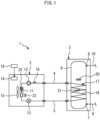
- Fig. 1 is a diagram showing a storage type hot water supplying apparatus 1 according to an embodiment 1.
- the storage type hot water supplying apparatus 1 according to the embodiment 1 includes a heat source machine 2 and a tank unit 3.
- the heat source machine 2 is located outdoors.
- the tank unit 3 may be located outdoors, or may be located in the room.
- the heat source machine 2 and the tank unit 3 are connected with each other via a refrigerant pipe 4, a refrigerant pipe 5, and an electric cable (not shown in the drawing).
- the storage type hot water supplying apparatus 1 may be a household hot water supplying apparatus or a commercial hot water supplying apparatus.
- a hot water storage tank 6 is provided in the tank unit 3.
- the hot water storage tank 6 in the present embodiment has a cylindrical profile.
- the center axis of the hot water storage tank 6 is substantially parallel to the vertical line.
- a temperature stratification is formed in which the upper portion of the temperature stratification has a high temperature and the lower portion of the temperature stratification has a low temperature.
- a feed water inlet 7 is located at the lower part of the hot water storage tank 6.
- a hot water outlet 8 is located at the higher part of the hot water storage tank 6.
- a feed water pipe 9 is connected to the feed water inlet 7.
- a hot water supply pipe 10 is connected to the hot water outlet 8.
- the downstream of the hot water supply pipe 10 is connected to a hot water supply terminal (not shown in the drawing) installed in the building.
- the hot water supply terminal may include, for example, at least one of a faucet, a shower, and a bathtub.
- Water supplied from a water source flows into the lower part of the hot water storage tank 6 through the feed water pipe 9, so that the inside of the hot water storage tank 6 is always maintained in a state of being fully filled with water.
- a water source such as a water supply
- hot water in the hot water storage tank 6 flows out to the hot water supply pipe 10 from the hot water outlet 8 due to a water pressure from the feed water pipe 9. With such outflow of hot water, the same amount of water flows into the lower part of the hot water storage tank 6 from the feed water pipe 9 through the feed water inlet 7.
- the hot water supply operation is an operation in which hot water in the hot water storage tank 6 flows out of the hot water outlet 8 and water flows into the hot water storage tank 6 from the feed water inlet 7.
- water to be fed to the hot water storage tank 6 from the feed water pipe 9 may be referred to as "feed water”.
- the heat source machine 2 is provided with an evaporator 11, a compressor 12, an expansion valve 13, and control circuitry 14, the evaporator 11 evaporating refrigerant, the compressor 12 compressing the refrigerant flowing out of the evaporator 11.
- the evaporator 11 in the present embodiment evaporates refrigerant by exchanging heat between outdoor air and refrigerant.
- the heat source machine 2 further includes a blower 15 for sending outdoor air to the evaporator 11.
- the storage type hot water supplying apparatus 1 further includes a condenser 17.
- the condenser 17 condenses refrigerant by exchanging heat between refrigerant compressed by the compressor 12 and water in the hot water storage tank 6.
- the condenser 17 has a refrigerant passage 18 located at the hot water storage tank 6.
- the refrigerant passage 18 is formed of a refrigerant pipe wound around the outer periphery of the hot water storage tank 6 in a helical shape or a coil shape.
- the refrigerant pipe forming the refrigerant passage 18 is in contact with the outer wall surface of the hot water storage tank 6. The heat of refrigerant flowing through the refrigerant passage 18 is transferred to the peripheral wall of the hot water storage tank 6.
- the heat transferred to the peripheral wall of the hot water storage tank 6 is transferred to water in the hot water storage tank 6, so that the water in the hot water storage tank 6 is heated.
- the refrigerant passage 18 is located such that the position of the refrigerant passage 18 gradually descends from the upstream side toward the downstream side of the refrigerant passage 18 while winding around the outer periphery of the hot water storage tank 6.
- Refrigerant compressed by the compressor 12 moves to the tank unit 3 from the heat source machine 2 through the refrigerant pipe 4, and flows into the inlet of the condenser 17, that is, into the inlet of the refrigerant passage 18.
- the refrigerant flowing out of the outlet of the condenser 17, that is, the outlet of the refrigerant passage 18, returns to the heat source machine 2 from the tank unit 3 through the refrigerant pipe 5, and flows into the expansion valve 13.
- the uppermost part of the condenser 17, that is, the inlet portion of the refrigerant passage 18 is located at a position lower than the hot water outlet 8.
- the lowermost part of the condenser 17, that is, the outlet portion of the refrigerant passage 18, is located at a height position substantially equal to the feed water inlet 7 or at a height position slightly higher than the feed water inlet 7.
- the refrigerant passage 18 is located in a region close to the lower side. That is, of the barrel portion of the hot water storage tank 6, the refrigerant passage 18 is not located in the upper region.
- the hot water storage tank 6 and the condenser 17 are covered by a heat insulating material (not shown in the drawing) provided in the tank unit 3.
- the refrigerant passage 18 of the condenser 17 is provided outside the hot water storage tank 6.
- the refrigerant passage 18 of the condenser 17 may be provided in the hot water storage tank 6.
- a helical-shaped or a coil-shaped refrigerant pipe forming the refrigerant passage 18 may be installed in a state of being in contact with the inner wall surface of the hot water storage tank 6.
- a helical-shaped or a coil-shaped refrigerant pipe forming the refrigerant passage 18 may be located in the hot water storage tank 6 without being in contact with the inner wall surface of the hot water storage tank 6.
- the expansion valve 13 expands refrigerant flowing out of the condenser 17.
- the refrigerant is reduced in pressure when passing through the expansion valve 13.
- the expansion valve 13 may be a linear expansion valve the opening degree of which can be continuously controlled. After refrigerant passes through the expansion valve 13, the refrigerant flows into the evaporator 11. The refrigerant evaporated by the evaporator 11 flows into the compressor 12, and is compressed.
- the control circuitry 14 controls a hot water storage operation.
- the hot water storage operation is an operation to heat water in the hot water storage tank 6 with refrigerant flowing through the refrigerant passage 18 of the condenser 17.
- the control circuitry 14 may include at least one processor and at least one memory. At least one processor may achieve the respective functions of the control circuitry 14 by reading and executing a program stored in at least one memory.
- the control circuitry 14 may include at least one dedicated hardware.
- the control circuitry 14 may be, for example, single circuitry, composite circuitry, a programmed processor, a parallel-programmed processor, an ASIC (Application Specific Integrated Circuit), an FPGA (Field-Programmable Gate Array), or a combination of the above.
- control circuitry 14 is located in the heat source machine 2.
- control circuitry 14 may be located in the tank unit 3.
- the functions of the control circuitry 14 may be achieved by a controller located in the heat source machine 2 and a controller located in the tank unit 3 mutually communicating to cooperate with each other.
- At least some functions of the control circuitry 14 may be achieved by a cloud server connected via a network, such as the internet.
- the control circuitry 14 controls the operation of the compressor 12 and the opening degree of the expansion valve 13.
- the operation speed of the compressor 12 may be variable.
- the control circuitry 14 may variably control the operation speed of the compressor 12 by allowing the operating frequency of an electric motor included in the compressor 12 to be variably controlled by inverter control.
- a higher operating frequency of the compressor 12 causes a higher operation speed of the compressor 12.
- a higher operation speed of the compressor 12 causes a larger circulation amount of refrigerant, leading to a higher heating power.
- a heating power is the quantity of heat applied per unit time period to water in the hot water storage tank 6 from refrigerant, and the unit of heating power is the watt.
- the storage type hot water supplying apparatus 1 further includes a hot water supply detection sensor 19 capable of detecting that the hot water supply operation is started.
- the control circuitry 14 can receive signals from the hot water supply detection sensor 19 by wired communication or wireless communication.
- the hot water supply detection sensor 19 may adopt any method to detect that the hot water supply operation is started.
- the hot water supply terminal connected downstream of the hot water supply pipe 10 may be provided with the hot water supply detection sensor 19 that detects whether the hot water supply terminal is opened.
- the hot water supply detection sensor 19 When the user opens the hot water supply terminal, hot water flows out of the hot water supply terminal, so that the hot water supply operation is started. Therefore, by the hot water supply detection sensor 19 detecting that the hot water supply terminal is opened, it is possible to detect that the hot water supply operation is started.
- Other examples of the hot water supply detection sensor 19 will be described in an embodiment 2 and the following embodiments.
- the storage type hot water supplying apparatus 1 may further include at least one sensor selected from a discharge temperature sensor 16, a stored hot water temperature sensor 20, a condensation temperature sensor 21, an evaporation temperature sensor 22, and an outside air temperature sensor 23.
- the discharge temperature sensor 16 detects the temperature of refrigerant discharged from the compressor 12.
- compressor discharge temperature the temperature of refrigerant discharged from the compressor 12 is referred to as "compressor discharge temperature”.
- the stored hot water temperature sensor 20 is a sensor for detecting a stored hot water temperature.
- the temperature of water in the hot water storage tank 6 may be referred to as "tank water temperature”.
- the stored hot water temperature sensor 20 is attached to the hot water storage tank 6 at a position higher than the uppermost part of the condenser 17 and lower than the hot water outlet 8.
- the stored hot water temperature sensor 20 detects, as "stored hot water temperature", a tank water temperature at such a position.
- the condensation temperature sensor 21 is a sensor for detecting the condensation temperature of refrigerant in the condenser 17.
- the condensation temperature sensor 21 is attached to the refrigerant passage 18 at a position close to the center of the entire length of the refrigerant passage 18.
- the evaporation temperature sensor 22 is a sensor for detecting the evaporation temperature of refrigerant in the evaporator 11.
- the outside air temperature sensor 23 is a sensor for detecting the temperature of outdoor air before the outdoor air exchanges heat in the evaporator 11.
- control circuitry 14 may determine a target discharge temperature according to the condensation temperature detected by the condensation temperature sensor 21 and the evaporation temperature detected by the evaporation temperature sensor 22, and may adjust the opening degree of the expansion valve 13 such that the compressor discharge temperature detected by the discharge temperature sensor 16 becomes equal to the target discharge temperature.
- the control circuitry 14 increases the opening degree of the expansion valve 13. Such an operation brings about an advantage of increasing the COP (Coefficient Of Performance) of a heat pump during the hot water storage operation. The reason will be described hereinafter.
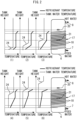
- Fig. 2 is a graph illustrating a change in tank water temperature distribution along the vertical direction and a change in refrigerant temperature distribution in the condenser 17 in the case in which the hot water supply operation is started during the hot water storage operation.
- tank water temperature and refrigerant temperature are shown on the horizontal axis, and position along the vertical direction is shown on the vertical axis.
- the temperature of refrigerant flowing out of the condenser 17 is referred to as "condenser outlet temperature”.
- the graph in Fig. 2(1) shows an example of temperature distribution in the case in which the hot water supply operation is not started during the hot water storage operation.
- a refrigerant temperature at a portion having a constant refrigerant temperature along the vertical direction corresponds to a condensation temperature.
- a difference between a refrigerant temperature at the inlet of the condenser 17 and a condensation temperature is referred to as "degree of superheat”.
- degree of superheat A difference between a refrigerant temperature at the inlet of the condenser 17 is substantially equal to a compressor discharge temperature.
- a difference between a condensation temperature and a condenser outlet temperature is referred to as "degree of subcooling”. In general, the degree of subcooling is also referred to as "subcooling".
- the control circuitry 14 may gradually reduce the opening degree of the expansion valve 13 such that a compressor discharge temperature gradually rises as a stored hot water temperature and a condensation temperature gradually rise.
- the graphs in Fig. 2(2) to Fig. 2(6) sequentially illustrate a change in temperature distribution in the case in which the hot water supply operation is started during the hot water storage operation.
- the graphs of refrigerant temperature distribution in Fig. 2(3) to Fig. 2(6) show changes in refrigerant temperature distribution in the case in which the control circuitry 14 does not increase the opening degree of the expansion valve 13. That is, Fig. 2(3) to Fig. 2(6) correspond to comparison examples of the present embodiment.
- the graph in Fig. 2(2) shows temperature distribution at the point in time slightly after the hot water supply operation is started.
- feed water at a temperature lower than a stored hot water temperature flows into the lower part in the hot water storage tank 6 from the feed water inlet 7.
- the tank water temperature at the lower part in the hot water storage tank 6 falls.
- the condenser outlet temperature falls, resulting in an increase in the degree of subcooling.
- the tank water temperature at the position of the condensation temperature sensor 21 does not yet fall and hence, the detected temperature from the condensation temperature sensor 21 does not yet start to fall.
- the stored hot water temperature detected by the stored hot water temperature sensor 20 also does not yet start to fall.
- the control circuitry 14 cannot immediately detect that the hot water supply operation is started.
- a temperature boundary layer between low-temperature feed water flowing into the hot water storage tank 6 and hot water in the hot water storage tank 6 is referred to as "temperature boundary layer 24".
- the state shown in Fig. 2(3) occurs.
- Fig. 2(3) shows temperature distribution at the point in time at which the temperature boundary layer 24 reaches the position of the condensation temperature sensor 21. From such a point in time, the detected temperature from the condensation temperature sensor 21 starts to fall.
- the refrigerant temperature in the refrigerant passage 18 at portions lower than the position of the condensation temperature sensor 21 is lower than the condensation temperature. That is, the refrigerant passage 18 at the portions lower than the position of the condensation temperature sensor 21 is filled with liquid refrigerant being liquefied refrigerant.
- the amount of refrigerant in the evaporator 11 decreases, the evaporator 11 being a low-pressure portion in the refrigerant circuitry.
- Fig. 2(4) shows temperature distribution at the point in time at which the temperature boundary layer 24 reaches a position higher than the condensation temperature sensor 21. At such a point in time, the detected temperature from the condensation temperature sensor 21 is lower than an actual condensation temperature. As described above, the detected temperature from the condensation temperature sensor 21 starts to fall after the temperature boundary layer 24 moves upward to a position higher than the condensation temperature sensor 21.
- Fig. 2(5) shows temperature distribution at the point in time at which the temperature boundary layer 24 reaches a position directly below the stored hot water temperature sensor 20. From such a point in time, the detected temperature from the stored hot water temperature sensor 20 starts to fall.
- Fig. 2(6) shows temperature distribution at the point in time at which the temperature boundary layer 24 reaches a position higher than the stored hot water temperature sensor 20. At such a point in time, the value of the detected temperature from the stored hot water temperature sensor 20 is substantially equal to the temperature of feed water.
- the control circuitry 14 increases the opening degree of the expansion valve 13.
- the control circuitry 14 may increase the opening degree of the expansion valve 13 at the point in time of Fig. 2(2) .
- the opening degree of the expansion valve 13 increases, the flow rate of refrigerant flowing to the evaporator 11 from the condenser 17 increases.
- the amount of refrigerant in the evaporator 11 becomes larger than that in the comparison example and hence, it is possible to surely avoid a fall in evaporation temperature and evaporation pressure.
- the present embodiment can surely prevent a large amount of liquid refrigerant from accumulating in the condenser 17 and hence, it is possible to surely prevent the shift of the state from the state shown in Fig. 2(2) to the state shown in Fig. 2(3) or following states. Therefore, the present embodiment has an advantage of increasing the COP.
- Fig. 3 is a flowchart showing an example of a process executed by the storage type hot water supplying apparatus 1 according to the embodiment 1.
- the control circuitry 14 starts a hot water storage operation.
- the control circuitry 14 determines whether the hot water supply detection sensor 19 detects, during the execution of the hot water storage operation, that the hot water supply operation is started.
- the control circuitry 14 increases the opening degree of the expansion valve 13 in step S3. Thereafter, the control circuitry 14 continues the hot water storage operation in step S4.
- step S2 when the hot water supply detection sensor 19 does not detect in step S2 that the hot water supply operation is started, the control circuitry 14 skips step S3 and advances to step S4 where the hot water storage operation is continued without any change.
- Fig. 4 is a diagram showing a storage type hot water supplying apparatus 25 according to the embodiment 2.
- the storage type hot water supplying apparatus 25 according to the embodiment 2 includes a condenser outlet temperature sensor 26.
- the condenser outlet temperature sensor 26 is attached to the outlet of the condenser 17, that is, to the outlet of the refrigerant passage 18.
- the condenser outlet temperature sensor 26 in the present embodiment corresponds to the hot water supply detection sensor 19.
- the control circuitry 14 increases the opening degree of the expansion valve 13.
- the condenser outlet temperature sensor 26 is located at the lower part of the hot water storage tank 6, thus easily affected by changes in tank water temperature at the lower part of the hot water storage tank 6. Therefore, when the hot water supply operation is started during the hot water storage operation, so that feed water starts to flow into the lower part of the hot water storage tank 6, a condenser outlet temperature immediately falls. Accordingly, with the condenser outlet temperature sensor 26, it is possible to rapidly detect that the hot water supply operation is started.
- Fig. 5 is a flowchart showing an example of a process executed by the storage type hot water supplying apparatus 25 according to the embodiment 2.
- the control circuitry 14 starts a hot water storage operation.
- the control circuitry 14 determines whether the condenser outlet temperature sensor 26 detects, during the execution of the hot water storage operation, that the hot water supply operation is started. For example, when the amount of fall in the detected temperature from the condenser outlet temperature sensor 26 exceeds the reference, the control circuitry 14 may assume that the hot water supply operation is started. Alternatively, when the amount of increase in a difference between the detected temperature from the condenser outlet temperature sensor 26 and the detected temperature from the condensation temperature sensor 21 exceeds the reference, the control circuitry 14 may assume that the hot water supply operation is started.
- step S12 When the condenser outlet temperature sensor 26 detects in step S12 that the hot water supply operation is started, the control circuitry 14 increases the opening degree of the expansion valve 13 in step S13. Thereafter, the control circuitry 14 continues the hot water storage operation in step S14.
- step S12 when the condenser outlet temperature sensor 26 does not detect in step S12 that the hot water supply operation is started, the control circuitry 14 skips step S13 and advances to step S14 where the hot water storage operation is continued without any change.
- the present embodiment has an advantage that it is unnecessary to attach the hot water supply detection sensor 19 to the hot water supply terminal installed in the building.
- Fig. 6 is a diagram showing a storage type hot water supplying apparatus 27 according to the embodiment 3.
- the storage type hot water supplying apparatus 27 according to the embodiment 3 includes a feed water temperature sensor 28.
- the feed water temperature sensor 28 detects the temperature of feed water flowing into the hot water storage tank 6 from the feed water inlet 7.
- the feed water temperature sensor 28 is attached to the lower part of the hot water storage tank 6.
- the feed water temperature sensor 28 may be located at a height position substantially equal to the height position of the feed water inlet 7.
- the feed water temperature sensor 28 may be located at a position lower than the feed water inlet 7.
- the feed water temperature sensor 28 may be located at a position slightly higher than the feed water inlet 7.
- the feed water temperature sensor 28 in the present embodiment corresponds to the hot water supply detection sensor 19.
- the control circuitry 14 increases the opening degree of the expansion valve 13.
- Fig. 7 is a flowchart showing an example of a process executed by the storage type hot water supplying apparatus 27 according to the embodiment 3.
- the control circuitry 14 starts a hot water storage operation.
- the control circuitry 14 determines whether the feed water temperature sensor 28 detects, during the execution of the hot water storage operation, that the hot water supply operation is started. For example, when the amount of fall in the detected temperature from the feed water temperature sensor 28 exceeds the reference, the control circuitry 14 may assume that the hot water supply operation is started.
- step S22 When the feed water temperature sensor 28 detects in step S22 that the hot water supply operation is started, the control circuitry 14 increases the opening degree of the expansion valve 13 in step S23. Thereafter, the control circuitry 14 continues the hot water storage operation in step S24.
- step S22 when the feed water temperature sensor 28 does not detect in step S22 that the hot water supply operation is started, the control circuitry 14 skips step S23 and advances to step S24 where the hot water storage operation is continued without any change.
- the present embodiment has an advantage that it is unnecessary to attach the hot water supply detection sensor 19 to the hot water supply terminal installed in the building.
- the control circuitry 14 may increase the opening degree of the expansion valve 13 as the temperature of feed water flowing into the hot water storage tank 6 decreases.
- the control circuitry 14 may increase the opening degree of the expansion valve 13 as the value of the detected temperature from the feed water temperature sensor 28 decreases.
- the control circuitry 14 may increase the opening degree of the expansion valve 13 as the amount of fall in the detected temperature from the feed water temperature sensor 28 increases.
- the same opening degree of the expansion valve 13 is adopted, the lower temperature of feed water flowing into the hot water storage tank 6 is likely to cause the amount of liquid refrigerant accumulating in the condenser 17 to increase.
- by increasing the opening degree of the expansion valve 13 as the temperature of feed water flowing into the hot water storage tank 6 decreases it is possible to further surely prevent an increase in the amount of liquid refrigerant in the condenser 17.
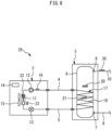
- Fig. 8 is a diagram showing a storage type hot water supplying apparatus 29 according to the embodiment 4.
- the storage type hot water supplying apparatus 29 according to the embodiment 4 includes a hot water supply temperature sensor 30.
- the hot water supply temperature sensor 30 detects the temperature of hot water flowing out of the hot water outlet 8.
- the hot water supply temperature sensor 30 is attached to the hot water supply pipe 10.
- the hot water supply temperature sensor 30 in the present embodiment corresponds to the hot water supply detection sensor 19.
- the control circuitry 14 increases the opening degree of the expansion valve 13.
- the detected temperature from the hot water supply temperature sensor 30 immediately rises. Accordingly, with the hot water supply temperature sensor 30, it is possible to rapidly detect that the hot water supply operation is started.
- Fig. 9 is a flowchart showing an example of a process executed by the storage type hot water supplying apparatus 29 according to the embodiment 4.
- the control circuitry 14 starts a hot water storage operation.
- the control circuitry 14 determines whether the hot water supply temperature sensor 30 detects, during the execution of the hot water storage operation, that the hot water supply operation is started. For example, when the rising amount of the detected temperature from the hot water supply temperature sensor 30 exceeds the reference, the control circuitry 14 may assume that the hot water supply operation is started.
- step S32 When the hot water supply temperature sensor 30 detects in step S32 that the hot water supply operation is started, the control circuitry 14 increases the opening degree of the expansion valve 13 in step S33. Thereafter, the control circuitry 14 continues the hot water storage operation in step S34.
- step S32 when the hot water supply temperature sensor 30 does not detect in step S32 that the hot water supply operation is started, the control circuitry 14 skips step S33 and advances to step S34 where the hot water storage operation is continued without any change.
- the present embodiment has an advantage that it is unnecessary to attach the hot water supply detection sensor 19 to the hot water supply terminal installed in the building.
- Fig. 10 is a diagram showing a storage type hot water supplying apparatus 31 according to the embodiment 5.
- the storage type hot water supplying apparatus 31 according to the embodiment 5 includes a flow sensor 32.
- the flow sensor 32 detects the presence or absence of a water flow at the feed water inlet 7.
- the flow sensor 32 is attached to the feed water pipe 9.
- the flow sensor 32 may be attached to the feed water inlet 7.
- a configuration may be adopted in which the flow sensor 32 is attached to the hot water outlet 8 or the hot water supply pipe 10, and the flow sensor 32 detects the presence or absence of a water flow at the hot water outlet 8 or in the hot water supply pipe 10.
- the flow sensor 32 in the present embodiment corresponds to the hot water supply detection sensor 19.
- the control circuitry 14 increases the opening degree of the expansion valve 13.
- the flow sensor 32 When the hot water supply operation is started during the hot water storage operation, the flow sensor 32 immediately detects a water flow. Accordingly, with the flow sensor 32, it is possible to rapidly detect that the hot water supply operation is started.
- the flow sensor 32 may be a sensor that is capable of detecting only the presence or absence of a water flow.
- the flow sensor 32 may be a sensor capable of detecting the flow rate of water passing through the feed water inlet 7 or the hot water outlet 8. The flow rate of water passing through the feed water inlet 7 is equal to the flow rate of water passing through the hot water outlet 8.
- Fig. 11 is a flowchart showing an example of a process executed by the storage type hot water supplying apparatus 31 according to the embodiment 5.
- the control circuitry 14 starts a hot water storage operation.
- the control circuitry 14 determines whether the flow sensor 32 detects, during the execution of the hot water storage operation, that the hot water supply operation is started. For example, when the flow rate detected by the flow sensor 32 exceeds the reference, the control circuitry 14 may assume that the hot water supply operation is started.
- step S42 When the flow sensor 32 detects in step S42 that the hot water supply operation is started, the control circuitry 14 increases the opening degree of the expansion valve 13 in step S43. Thereafter, the control circuitry 14 continues the hot water storage operation in step S44.
- step S42 when the flow sensor 32 does not detect in step S42 that the hot water supply operation is started, the control circuitry 14 skips step S43 and advances to step S44 where the hot water storage operation is continued without any change.
- the present embodiment has an advantage that it is unnecessary to attach the hot water supply detection sensor 19 to the hot water supply terminal installed in the building.
- step S43 the control circuitry 14 may increase the opening degree of the expansion valve 13 as the flow rate detected by the flow sensor 32 increases.
- the same opening degree of the expansion valve 13 is adopted, a larger flow rate of water flowing into the hot water storage tank 6 from the feed water inlet 7 causes the water temperature in the lower part in the hot water storage tank 6 to fall faster and hence, the amount of liquid refrigerant accumulating in the condenser 17 is likely to increase.
- by increasing the opening degree of the expansion valve 13 as the flow rate detected by the flow sensor 32 increases it is possible to further surely prevent an increase in the amount of liquid refrigerant in the condenser 17.
- the hot water supply detection sensor 19 is not limited to the configurations described in the respective embodiments.
- the hot water supply detection sensor 19 may be, for example, a sensor that detects sounds or vibrations generated from the feed water inlet 7, the hot water outlet 8, the feed water pipe 9, or the hot water supply pipe 10.
- the hot water supply detection sensor 19 may be, for example, a sensor that detects sounds or vibrations generated from the feed water inlet 7, the hot water outlet 8, the feed water pipe 9, or the hot water supply pipe 10.
Landscapes
- Engineering & Computer Science (AREA)
- Physics & Mathematics (AREA)
- Thermal Sciences (AREA)
- Chemical & Material Sciences (AREA)
- Combustion & Propulsion (AREA)
- Mechanical Engineering (AREA)
- General Engineering & Computer Science (AREA)
- Fluid Mechanics (AREA)
- Heat-Pump Type And Storage Water Heaters (AREA)
Abstract
Description
- The present disclosure relates to a storage type hot water supplying apparatus. Background
- A heat pump hot water supplying apparatus disclosed in the following
PTL 1 includes heat pump circuitry, water circulation circuitry, a feed water pipe, and a hot water supply pipe, and is configured such that the feed water pipe is connected to the inlet of a hot water supply tank and to the inlet of a water heater in a branched manner, the hot water supply pipe is connected to the outlet of the hot water supply tank and to the outlet of the water heater in a branched manner, and valves are provided to switch between hot water supply from the hot water supply tank and hot water supply from the water heater. A water heat exchanger including the water heater and a condenser is wound in a spiral to form a cylindrical shape, and is installed so as to surround the hot water supply tank. - [PTL 1]
JP 2003-314892 A - For a storage type hot water supplying apparatus in which a condenser is located at a hot water storage tank, there is a need to further increase the COP (Coefficient Of Performance) during a hot water storage operation in order to further save energy.
- The present disclosure has been made to solve the above-described problem, and it is an object of the present disclosure to provide a storage type hot water supplying apparatus that has an advantage of increasing the COP during the hot water storage operation.
- A storage type hot water supplying apparatus according to the present disclosure includes: a hot water storage tank; a feed water inlet located at a lower part of the hot water storage tank; a hot water outlet located at a higher part of the hot water storage tank; an evaporator for evaporating refrigerant;
a compressor for compressing the refrigerant flowing out of the evaporator; a condenser having a refrigerant passage located at the hot water storage tank, the condenser being configured to condense the refrigerant by exchanging heat between the refrigerant compressed by the compressor and water in the hot water storage tank; an expansion valve for expanding the refrigerant flowing out of the condenser; control circuitry configured to control a hot water storage operation, the hot water storage operation being an operation to heat the water in the hot water storage tank with the refrigerant flowing through the refrigerant passage of the condenser; and a hot water supply detection sensor capable of detecting that a hot water supply operation is started, the hot water supply operation being an operation in which hot water in the hot water storage tank flows out of the hot water outlet and water flows into the hot water storage tank from the feed water inlet. The control circuitry is configured to increase an opening degree of the expansion valve when the hot water supply operation is started during the hot water storage operation. - According to the present disclosure, it is possible to provide a storage type hot water supplying apparatus that has an advantage of increasing the COP during the hot water storage operation.
-
-
Fig. 1 is a diagram showing a storage type hotwater supplying apparatus 1 according to anembodiment 1. -
Fig. 2 is a graph illustrating a change in tank water temperature distribution along the vertical direction and a change in refrigerant temperature distribution in a condenser in the case in which a hot water supply operation is started during a hot water storage operation. -
Fig. 3 is a flowchart showing an example of a process executed by the storage type hot water supplying apparatus according to theembodiment 1. -
Fig. 4 is a diagram showing a storage type hot water supplying apparatus according to anembodiment 2. -
Fig. 5 is a flowchart showing an example of a process executed by the storage type hot water supplying apparatus according to theembodiment 2. -
Fig. 6 is a diagram showing a storage type hot water supplying apparatus according to anembodiment 3. -
Fig. 7 is a flowchart showing an example of a process executed by the storage type hot water supplying apparatus according to theembodiment 3. -
Fig. 8 is a diagram showing a storage type hot water supplying apparatus according to anembodiment 4. -
Fig. 9 is a flowchart showing an example of a process executed by the storage type hot water supplying apparatus according to theembodiment 4. -
Fig. 10 is a diagram showing a storage type hot water supplying apparatus according to anembodiment 5. -
Fig. 11 is a flowchart showing an example of a process executed by the storage type hot water supplying apparatus according to theembodiment 5. - Hereinafter, embodiments will be described with reference to drawings. In the respective drawings, the identical or corresponding elements are given the same reference symbols, and the description of such elements will be simplified or omitted. In the description made hereinafter, in principle, the term "water" or "hot water" means liquid water, and includes cold water and boiling water.
-
Fig. 1 is a diagram showing a storage type hotwater supplying apparatus 1 according to anembodiment 1. As shown inFig. 1 , the storage type hotwater supplying apparatus 1 according to theembodiment 1 includes aheat source machine 2 and atank unit 3. Theheat source machine 2 is located outdoors. Thetank unit 3 may be located outdoors, or may be located in the room. Theheat source machine 2 and thetank unit 3 are connected with each other via arefrigerant pipe 4, arefrigerant pipe 5, and an electric cable (not shown in the drawing). The storage type hotwater supplying apparatus 1 may be a household hot water supplying apparatus or a commercial hot water supplying apparatus. - A hot
water storage tank 6 is provided in thetank unit 3. The hotwater storage tank 6 in the present embodiment has a cylindrical profile. The center axis of the hotwater storage tank 6 is substantially parallel to the vertical line. In the hotwater storage tank 6, due to a difference in the density of water at different temperatures, a temperature stratification is formed in which the upper portion of the temperature stratification has a high temperature and the lower portion of the temperature stratification has a low temperature. - A
feed water inlet 7 is located at the lower part of the hotwater storage tank 6. Ahot water outlet 8 is located at the higher part of the hotwater storage tank 6. Afeed water pipe 9 is connected to thefeed water inlet 7. A hotwater supply pipe 10 is connected to thehot water outlet 8. The downstream of the hotwater supply pipe 10 is connected to a hot water supply terminal (not shown in the drawing) installed in the building. The hot water supply terminal may include, for example, at least one of a faucet, a shower, and a bathtub. - Water supplied from a water source, such as a water supply, for example, flows into the lower part of the hot
water storage tank 6 through thefeed water pipe 9, so that the inside of the hotwater storage tank 6 is always maintained in a state of being fully filled with water. In performing a hot water supply operation in which hot water is supplied to the hot water supply terminal, hot water in the hotwater storage tank 6 flows out to the hotwater supply pipe 10 from thehot water outlet 8 due to a water pressure from thefeed water pipe 9. With such outflow of hot water, the same amount of water flows into the lower part of the hotwater storage tank 6 from thefeed water pipe 9 through thefeed water inlet 7. As described above, the hot water supply operation is an operation in which hot water in the hotwater storage tank 6 flows out of thehot water outlet 8 and water flows into the hotwater storage tank 6 from thefeed water inlet 7. Hereinafter, water to be fed to the hotwater storage tank 6 from thefeed water pipe 9 may be referred to as "feed water". - The
heat source machine 2 is provided with anevaporator 11, acompressor 12, anexpansion valve 13, andcontrol circuitry 14, theevaporator 11 evaporating refrigerant, thecompressor 12 compressing the refrigerant flowing out of theevaporator 11. Theevaporator 11 in the present embodiment evaporates refrigerant by exchanging heat between outdoor air and refrigerant. In the example shown in the drawing, theheat source machine 2 further includes ablower 15 for sending outdoor air to theevaporator 11. - The storage type hot
water supplying apparatus 1 further includes acondenser 17. Thecondenser 17 condenses refrigerant by exchanging heat between refrigerant compressed by thecompressor 12 and water in the hotwater storage tank 6. Thecondenser 17 has arefrigerant passage 18 located at the hotwater storage tank 6. In the present embodiment, therefrigerant passage 18 is formed of a refrigerant pipe wound around the outer periphery of the hotwater storage tank 6 in a helical shape or a coil shape. The refrigerant pipe forming therefrigerant passage 18 is in contact with the outer wall surface of the hotwater storage tank 6. The heat of refrigerant flowing through therefrigerant passage 18 is transferred to the peripheral wall of the hotwater storage tank 6. The heat transferred to the peripheral wall of the hotwater storage tank 6 is transferred to water in the hotwater storage tank 6, so that the water in the hotwater storage tank 6 is heated. Therefrigerant passage 18 is located such that the position of therefrigerant passage 18 gradually descends from the upstream side toward the downstream side of therefrigerant passage 18 while winding around the outer periphery of the hotwater storage tank 6. - Refrigerant compressed by the
compressor 12 moves to thetank unit 3 from theheat source machine 2 through therefrigerant pipe 4, and flows into the inlet of thecondenser 17, that is, into the inlet of therefrigerant passage 18. The refrigerant flowing out of the outlet of thecondenser 17, that is, the outlet of therefrigerant passage 18, returns to theheat source machine 2 from thetank unit 3 through therefrigerant pipe 5, and flows into theexpansion valve 13. The uppermost part of thecondenser 17, that is, the inlet portion of therefrigerant passage 18 is located at a position lower than thehot water outlet 8. The lowermost part of thecondenser 17, that is, the outlet portion of therefrigerant passage 18, is located at a height position substantially equal to thefeed water inlet 7 or at a height position slightly higher than thefeed water inlet 7. In the example shown in the drawing, of the barrel portion of the hotwater storage tank 6, therefrigerant passage 18 is located in a region close to the lower side. That is, of the barrel portion of the hotwater storage tank 6, therefrigerant passage 18 is not located in the upper region. The hotwater storage tank 6 and thecondenser 17 are covered by a heat insulating material (not shown in the drawing) provided in thetank unit 3. - In the present embodiment, the
refrigerant passage 18 of thecondenser 17 is provided outside the hotwater storage tank 6. As a modification, therefrigerant passage 18 of thecondenser 17 may be provided in the hotwater storage tank 6. For example, a helical-shaped or a coil-shaped refrigerant pipe forming therefrigerant passage 18 may be installed in a state of being in contact with the inner wall surface of the hotwater storage tank 6. Alternatively, a helical-shaped or a coil-shaped refrigerant pipe forming therefrigerant passage 18 may be located in the hotwater storage tank 6 without being in contact with the inner wall surface of the hotwater storage tank 6. - The
expansion valve 13 expands refrigerant flowing out of thecondenser 17. The refrigerant is reduced in pressure when passing through theexpansion valve 13. Theexpansion valve 13 may be a linear expansion valve the opening degree of which can be continuously controlled. After refrigerant passes through theexpansion valve 13, the refrigerant flows into theevaporator 11. The refrigerant evaporated by theevaporator 11 flows into thecompressor 12, and is compressed. - The
control circuitry 14 controls a hot water storage operation. The hot water storage operation is an operation to heat water in the hotwater storage tank 6 with refrigerant flowing through therefrigerant passage 18 of thecondenser 17. Thecontrol circuitry 14 may include at least one processor and at least one memory. At least one processor may achieve the respective functions of thecontrol circuitry 14 by reading and executing a program stored in at least one memory. Thecontrol circuitry 14 may include at least one dedicated hardware. Thecontrol circuitry 14 may be, for example, single circuitry, composite circuitry, a programmed processor, a parallel-programmed processor, an ASIC (Application Specific Integrated Circuit), an FPGA (Field-Programmable Gate Array), or a combination of the above. - In the example shown in the drawing, the
control circuitry 14 is located in theheat source machine 2. However, as a modification, thecontrol circuitry 14 may be located in thetank unit 3. The functions of thecontrol circuitry 14 may be achieved by a controller located in theheat source machine 2 and a controller located in thetank unit 3 mutually communicating to cooperate with each other. At least some functions of thecontrol circuitry 14 may be achieved by a cloud server connected via a network, such as the internet. - During the hot water storage operation, the
control circuitry 14 controls the operation of thecompressor 12 and the opening degree of theexpansion valve 13. The operation speed of thecompressor 12 may be variable. Thecontrol circuitry 14 may variably control the operation speed of thecompressor 12 by allowing the operating frequency of an electric motor included in thecompressor 12 to be variably controlled by inverter control. A higher operating frequency of thecompressor 12 causes a higher operation speed of thecompressor 12. A higher operation speed of thecompressor 12 causes a larger circulation amount of refrigerant, leading to a higher heating power. A heating power is the quantity of heat applied per unit time period to water in the hotwater storage tank 6 from refrigerant, and the unit of heating power is the watt. - The storage type hot
water supplying apparatus 1 further includes a hot watersupply detection sensor 19 capable of detecting that the hot water supply operation is started. Thecontrol circuitry 14 can receive signals from the hot watersupply detection sensor 19 by wired communication or wireless communication. The hot watersupply detection sensor 19 may adopt any method to detect that the hot water supply operation is started. For example, the hot water supply terminal connected downstream of the hotwater supply pipe 10 may be provided with the hot watersupply detection sensor 19 that detects whether the hot water supply terminal is opened. When the user opens the hot water supply terminal, hot water flows out of the hot water supply terminal, so that the hot water supply operation is started. Therefore, by the hot watersupply detection sensor 19 detecting that the hot water supply terminal is opened, it is possible to detect that the hot water supply operation is started. Other examples of the hot watersupply detection sensor 19 will be described in anembodiment 2 and the following embodiments. - As in the case of the example shown in the drawing, the storage type hot
water supplying apparatus 1 may further include at least one sensor selected from adischarge temperature sensor 16, a stored hotwater temperature sensor 20, acondensation temperature sensor 21, anevaporation temperature sensor 22, and an outsideair temperature sensor 23. Thedischarge temperature sensor 16 detects the temperature of refrigerant discharged from thecompressor 12. In the description made hereinafter, the temperature of refrigerant discharged from thecompressor 12 is referred to as "compressor discharge temperature". - The stored hot
water temperature sensor 20 is a sensor for detecting a stored hot water temperature. Hereinafter, the temperature of water in the hotwater storage tank 6 may be referred to as "tank water temperature". In the example shown in the drawing, the stored hotwater temperature sensor 20 is attached to the hotwater storage tank 6 at a position higher than the uppermost part of thecondenser 17 and lower than thehot water outlet 8. The stored hotwater temperature sensor 20 detects, as "stored hot water temperature", a tank water temperature at such a position. - The
condensation temperature sensor 21 is a sensor for detecting the condensation temperature of refrigerant in thecondenser 17. In the example shown in the drawing, thecondensation temperature sensor 21 is attached to therefrigerant passage 18 at a position close to the center of the entire length of therefrigerant passage 18. - The
evaporation temperature sensor 22 is a sensor for detecting the evaporation temperature of refrigerant in theevaporator 11. The outsideair temperature sensor 23 is a sensor for detecting the temperature of outdoor air before the outdoor air exchanges heat in theevaporator 11. - During the hot water storage operation, the
control circuitry 14 may determine a target discharge temperature according to the condensation temperature detected by thecondensation temperature sensor 21 and the evaporation temperature detected by theevaporation temperature sensor 22, and may adjust the opening degree of theexpansion valve 13 such that the compressor discharge temperature detected by thedischarge temperature sensor 16 becomes equal to the target discharge temperature. - In the present embodiment, when the hot water
supply detection sensor 19 detects, during the hot water storage operation, that the hot water supply operation is started, thecontrol circuitry 14 increases the opening degree of theexpansion valve 13. Such an operation brings about an advantage of increasing the COP (Coefficient Of Performance) of a heat pump during the hot water storage operation. The reason will be described hereinafter. -
Fig. 2 is a graph illustrating a change in tank water temperature distribution along the vertical direction and a change in refrigerant temperature distribution in thecondenser 17 in the case in which the hot water supply operation is started during the hot water storage operation. In respective graphs inFig. 2(1) to Fig. 2(6) , tank water temperature and refrigerant temperature are shown on the horizontal axis, and position along the vertical direction is shown on the vertical axis. Hereinafter, the temperature of refrigerant flowing out of thecondenser 17 is referred to as "condenser outlet temperature". - The graph in
Fig. 2(1) shows an example of temperature distribution in the case in which the hot water supply operation is not started during the hot water storage operation. In this graph, a refrigerant temperature at a portion having a constant refrigerant temperature along the vertical direction corresponds to a condensation temperature. A difference between a refrigerant temperature at the inlet of thecondenser 17 and a condensation temperature is referred to as "degree of superheat". It can be assumed that a refrigerant temperature at the inlet of thecondenser 17 is substantially equal to a compressor discharge temperature. A difference between a condensation temperature and a condenser outlet temperature is referred to as "degree of subcooling". In general, the degree of subcooling is also referred to as "subcooling". - During the hot water storage operation, when water receives the heat of refrigerant passing through the
refrigerant passage 18, thus rising in temperature, the density of the water decreases and hence, the water moves upward in the hotwater storage tank 6 by obtaining buoyancy. Thus, convection is generated. Due to the generation of such convection, in the case in which the hot water supply operation is not started, as shown by the water temperature distribution in the graph inFig. 2(1) , a substantially constant tank water temperatures are distributed from the position close to the lowermost part of thecondenser 17 to the position close to the uppermost part of the hotwater storage tank 6. Such substantially constant distributed tank water temperatures are detected as stored hot water temperature by the stored hotwater temperature sensor 20. When a state with such a temperature distribution is maintained, the stored hot water temperature gradually rises. As a stored hot water temperature gradually rises, a condensation temperature also gradually rises. Thecontrol circuitry 14 may gradually reduce the opening degree of theexpansion valve 13 such that a compressor discharge temperature gradually rises as a stored hot water temperature and a condensation temperature gradually rise. - The graphs in
Fig. 2(2) to Fig. 2(6) sequentially illustrate a change in temperature distribution in the case in which the hot water supply operation is started during the hot water storage operation. The graphs of refrigerant temperature distribution inFig. 2(3) to Fig. 2(6) show changes in refrigerant temperature distribution in the case in which thecontrol circuitry 14 does not increase the opening degree of theexpansion valve 13. That is,Fig. 2(3) to Fig. 2(6) correspond to comparison examples of the present embodiment. - The graph in
Fig. 2(2) shows temperature distribution at the point in time slightly after the hot water supply operation is started. When the hot water supply operation is started, feed water at a temperature lower than a stored hot water temperature flows into the lower part in the hotwater storage tank 6 from thefeed water inlet 7. As a result, the tank water temperature at the lower part in the hotwater storage tank 6 falls. With such a fall in the tank water temperature, the condenser outlet temperature falls, resulting in an increase in the degree of subcooling. In contrast, the tank water temperature at the position of thecondensation temperature sensor 21 does not yet fall and hence, the detected temperature from thecondensation temperature sensor 21 does not yet start to fall. The stored hot water temperature detected by the stored hotwater temperature sensor 20 also does not yet start to fall. As described above, when the hot water supply operation is started, although the degree of subcooling increases, the detected temperature from thecondensation temperature sensor 21 does not change and the detected temperature from the stored hotwater temperature sensor 20 also does not change. For this reason, if the hot watersupply detection sensor 19 is not provided, thecontrol circuitry 14 cannot immediately detect that the hot water supply operation is started. - Hereinafter, a temperature boundary layer between low-temperature feed water flowing into the hot
water storage tank 6 and hot water in the hotwater storage tank 6 is referred to as "temperature boundary layer 24". When the hot water supply operation is continued from the state shown inFig. 2(2) , thus causing feed water to further flow into the hotwater storage tank 6, leading to further upward movement of the position of thetemperature boundary layer 24, the state shown inFig. 2(3) occurs.Fig. 2(3) shows temperature distribution at the point in time at which thetemperature boundary layer 24 reaches the position of thecondensation temperature sensor 21. From such a point in time, the detected temperature from thecondensation temperature sensor 21 starts to fall. At such a point in time, the refrigerant temperature in therefrigerant passage 18 at portions lower than the position of thecondensation temperature sensor 21 is lower than the condensation temperature. That is, therefrigerant passage 18 at the portions lower than the position of thecondensation temperature sensor 21 is filled with liquid refrigerant being liquefied refrigerant. When a large amount of liquid refrigerant accumulates in thecondenser 17, being the high-pressure portion in the refrigerant circuitry, as described above, the amount of refrigerant in theevaporator 11 decreases, theevaporator 11 being a low-pressure portion in the refrigerant circuitry. As a result, an evaporation temperature falls and an evaporation pressure falls, so that the degree of superheat of refrigerant at the outlet of theevaporator 11 increases. Therefore, the quantity of heat absorbed by refrigerant from outside air in theevaporator 11 decreases, leading to a fall in the COP of the heat pump. - When the hot water supply operation is further continued from the state shown in
Fig. 2(3) , thus causing feed water to further flow into the hotwater storage tank 6, leading to further upward movement of the position of thetemperature boundary layer 24, the state shown inFig. 2(4) occurs.Fig. 2(4) shows temperature distribution at the point in time at which thetemperature boundary layer 24 reaches a position higher than thecondensation temperature sensor 21. At such a point in time, the detected temperature from thecondensation temperature sensor 21 is lower than an actual condensation temperature. As described above, the detected temperature from thecondensation temperature sensor 21 starts to fall after thetemperature boundary layer 24 moves upward to a position higher than thecondensation temperature sensor 21. - When the hot water supply operation is further continued from the state shown in
Fig. 2(4) , thus causing feed water to further flow into the hotwater storage tank 6, leading to further upward movement of the position of thetemperature boundary layer 24, the state shown inFig. 2(5) occurs.Fig. 2(5) shows temperature distribution at the point in time at which thetemperature boundary layer 24 reaches a position directly below the stored hotwater temperature sensor 20. From such a point in time, the detected temperature from the stored hotwater temperature sensor 20 starts to fall. - When the hot water supply operation is further continued from the state shown in
Fig. 2(5) , thus causing feed water to further flow into the hotwater storage tank 6, leading to further upward movement of the position of thetemperature boundary layer 24, the state shown inFig. 2(6) occurs.Fig. 2(6) shows temperature distribution at the point in time at which thetemperature boundary layer 24 reaches a position higher than the stored hotwater temperature sensor 20. At such a point in time, the value of the detected temperature from the stored hotwater temperature sensor 20 is substantially equal to the temperature of feed water. - As the state shifts from the state shown in
Fig. 2(3) to the state shown inFig. 2(6) , a larger amount of liquid refrigerant further accumulates in thecondenser 17. As a result, the amount of refrigerant in theevaporator 11 becomes more insufficient, leading to a further fall in COP. - In contrast, in the present embodiment, when the hot water
supply detection sensor 19 detects that a hot water supply operation is started, thecontrol circuitry 14 increases the opening degree of theexpansion valve 13. For example, thecontrol circuitry 14 may increase the opening degree of theexpansion valve 13 at the point in time ofFig. 2(2) . When the opening degree of theexpansion valve 13 increases, the flow rate of refrigerant flowing to the evaporator 11 from thecondenser 17 increases. As a result, the amount of refrigerant in theevaporator 11 becomes larger than that in the comparison example and hence, it is possible to surely avoid a fall in evaporation temperature and evaporation pressure. Therefore, the quantity of heat absorbed by refrigerant from outside air in theevaporator 11 becomes larger than that in the comparison example and hence, the COP becomes higher than the COP in the comparison example. In this manner, the present embodiment can surely prevent a large amount of liquid refrigerant from accumulating in thecondenser 17 and hence, it is possible to surely prevent the shift of the state from the state shown inFig. 2(2) to the state shown inFig. 2(3) or following states. Therefore, the present embodiment has an advantage of increasing the COP. -
Fig. 3 is a flowchart showing an example of a process executed by the storage type hotwater supplying apparatus 1 according to theembodiment 1. In step S1 inFig. 3 , thecontrol circuitry 14 starts a hot water storage operation. Next, in step S2, thecontrol circuitry 14 determines whether the hot watersupply detection sensor 19 detects, during the execution of the hot water storage operation, that the hot water supply operation is started. When the hot watersupply detection sensor 19 detects that the hot water supply operation is started, thecontrol circuitry 14 increases the opening degree of theexpansion valve 13 in step S3. Thereafter, thecontrol circuitry 14 continues the hot water storage operation in step S4. - In contrast, when the hot water
supply detection sensor 19 does not detect in step S2 that the hot water supply operation is started, thecontrol circuitry 14 skips step S3 and advances to step S4 where the hot water storage operation is continued without any change. - Next, the
embodiment 2 will be described with reference toFig. 4 andFig. 5 . However, the description will be mainly made for points that make theembodiment 2 different from the above-describedembodiment 1, and the repeated description will be simplified or omitted. Further, elements identical or corresponding to the above-described elements are given the same reference symbols. -
Fig. 4 is a diagram showing a storage type hotwater supplying apparatus 25 according to theembodiment 2. As shown inFig. 4 , the storage type hotwater supplying apparatus 25 according to theembodiment 2 includes a condenseroutlet temperature sensor 26. The condenseroutlet temperature sensor 26 is attached to the outlet of thecondenser 17, that is, to the outlet of therefrigerant passage 18. The condenseroutlet temperature sensor 26 in the present embodiment corresponds to the hot watersupply detection sensor 19. In the present embodiment, when the condenseroutlet temperature sensor 26 detects, during the hot water storage operation, that the hot water supply operation is started, thecontrol circuitry 14 increases the opening degree of theexpansion valve 13. Thus, it is possible to obtain advantageous effects substantially the same as the advantageous effects of theembodiment 1. - The condenser
outlet temperature sensor 26 is located at the lower part of the hotwater storage tank 6, thus easily affected by changes in tank water temperature at the lower part of the hotwater storage tank 6. Therefore, when the hot water supply operation is started during the hot water storage operation, so that feed water starts to flow into the lower part of the hotwater storage tank 6, a condenser outlet temperature immediately falls. Accordingly, with the condenseroutlet temperature sensor 26, it is possible to rapidly detect that the hot water supply operation is started. -
Fig. 5 is a flowchart showing an example of a process executed by the storage type hotwater supplying apparatus 25 according to theembodiment 2. Instep S1 1 inFig. 5 , thecontrol circuitry 14 starts a hot water storage operation. Next, in step S12, thecontrol circuitry 14 determines whether the condenseroutlet temperature sensor 26 detects, during the execution of the hot water storage operation, that the hot water supply operation is started. For example, when the amount of fall in the detected temperature from the condenseroutlet temperature sensor 26 exceeds the reference, thecontrol circuitry 14 may assume that the hot water supply operation is started. Alternatively, when the amount of increase in a difference between the detected temperature from the condenseroutlet temperature sensor 26 and the detected temperature from thecondensation temperature sensor 21 exceeds the reference, thecontrol circuitry 14 may assume that the hot water supply operation is started. - When the condenser
outlet temperature sensor 26 detects in step S12 that the hot water supply operation is started, thecontrol circuitry 14 increases the opening degree of theexpansion valve 13 in step S13. Thereafter, thecontrol circuitry 14 continues the hot water storage operation in step S14. - In contrast, when the condenser
outlet temperature sensor 26 does not detect in step S12 that the hot water supply operation is started, thecontrol circuitry 14 skips step S13 and advances to step S14 where the hot water storage operation is continued without any change. - The present embodiment has an advantage that it is unnecessary to attach the hot water
supply detection sensor 19 to the hot water supply terminal installed in the building. - Next, an
embodiment 3 will be described with reference toFig. 6 andFig. 7 . However, the description will be mainly made for points that make theembodiment 3 different from the above-describedembodiment 1, and the repeated description will be simplified or omitted. Further, elements identical or corresponding to the above-described elements are given the same reference symbols. -
Fig. 6 is a diagram showing a storage type hotwater supplying apparatus 27 according to theembodiment 3. As shown inFig. 6 , the storage type hotwater supplying apparatus 27 according to theembodiment 3 includes a feedwater temperature sensor 28. The feedwater temperature sensor 28 detects the temperature of feed water flowing into the hotwater storage tank 6 from thefeed water inlet 7. The feedwater temperature sensor 28 is attached to the lower part of the hotwater storage tank 6. For example, the feedwater temperature sensor 28 may be located at a height position substantially equal to the height position of thefeed water inlet 7. The feedwater temperature sensor 28 may be located at a position lower than thefeed water inlet 7. Alternatively, the feedwater temperature sensor 28 may be located at a position slightly higher than thefeed water inlet 7. - The feed
water temperature sensor 28 in the present embodiment corresponds to the hot watersupply detection sensor 19. In the present embodiment, when the feedwater temperature sensor 28 detects, during the hot water storage operation, that the hot water supply operation is started, thecontrol circuitry 14 increases the opening degree of theexpansion valve 13. Thus, it is possible to obtain advantageous effects substantially the same as the advantageous effects of theembodiment 1. - When the hot water supply operation is started during the hot water storage operation, so that feed water starts to flow into the lower part of the hot
water storage tank 6, the detected temperature from the feedwater temperature sensor 28 immediately falls. Accordingly, with the feedwater temperature sensor 28, it is possible to rapidly detect that the hot water supply operation is started. -
Fig. 7 is a flowchart showing an example of a process executed by the storage type hotwater supplying apparatus 27 according to theembodiment 3. In step S21 inFig. 7 , thecontrol circuitry 14 starts a hot water storage operation. Next, in step S22, thecontrol circuitry 14 determines whether the feedwater temperature sensor 28 detects, during the execution of the hot water storage operation, that the hot water supply operation is started. For example, when the amount of fall in the detected temperature from the feedwater temperature sensor 28 exceeds the reference, thecontrol circuitry 14 may assume that the hot water supply operation is started. - When the feed
water temperature sensor 28 detects in step S22 that the hot water supply operation is started, thecontrol circuitry 14 increases the opening degree of theexpansion valve 13 in step S23. Thereafter, thecontrol circuitry 14 continues the hot water storage operation in step S24. - In contrast, when the feed
water temperature sensor 28 does not detect in step S22 that the hot water supply operation is started, thecontrol circuitry 14 skips step S23 and advances to step S24 where the hot water storage operation is continued without any change. - The present embodiment has an advantage that it is unnecessary to attach the hot water
supply detection sensor 19 to the hot water supply terminal installed in the building. - In step S23, the
control circuitry 14 may increase the opening degree of theexpansion valve 13 as the temperature of feed water flowing into the hotwater storage tank 6 decreases. For example, thecontrol circuitry 14 may increase the opening degree of theexpansion valve 13 as the value of the detected temperature from the feedwater temperature sensor 28 decreases. Alternatively, thecontrol circuitry 14 may increase the opening degree of theexpansion valve 13 as the amount of fall in the detected temperature from the feedwater temperature sensor 28 increases. When the same opening degree of theexpansion valve 13 is adopted, the lower temperature of feed water flowing into the hotwater storage tank 6 is likely to cause the amount of liquid refrigerant accumulating in thecondenser 17 to increase. In view of the above, by increasing the opening degree of theexpansion valve 13 as the temperature of feed water flowing into the hotwater storage tank 6 decreases, it is possible to further surely prevent an increase in the amount of liquid refrigerant in thecondenser 17. - Next, an
embodiment 4 will be described with reference toFig. 8 andFig. 9 . However, the description will be mainly made for points that make theembodiment 4 different from the above-describedembodiment 1, and the repeated description will be simplified or omitted. Further, elements identical or corresponding to the above-described elements are given the same reference symbols. -
Fig. 8 is a diagram showing a storage type hotwater supplying apparatus 29 according to theembodiment 4. As shown inFig. 8 , the storage type hotwater supplying apparatus 29 according to theembodiment 4 includes a hot watersupply temperature sensor 30. The hot watersupply temperature sensor 30 detects the temperature of hot water flowing out of thehot water outlet 8. The hot watersupply temperature sensor 30 is attached to the hotwater supply pipe 10. - The hot water
supply temperature sensor 30 in the present embodiment corresponds to the hot watersupply detection sensor 19. In the present embodiment, when the hot watersupply temperature sensor 30 detects, during the hot water storage operation, that the hot water supply operation is started, thecontrol circuitry 14 increases the opening degree of theexpansion valve 13. Thus, it is possible to obtain advantageous effects substantially the same as the advantageous effects of theembodiment 1. - When the hot water supply operation is started during the hot water storage operation, the detected temperature from the hot water
supply temperature sensor 30 immediately rises. Accordingly, with the hot watersupply temperature sensor 30, it is possible to rapidly detect that the hot water supply operation is started. -
Fig. 9 is a flowchart showing an example of a process executed by the storage type hotwater supplying apparatus 29 according to theembodiment 4. In step S31 inFig. 9 , thecontrol circuitry 14 starts a hot water storage operation. Next, in step S32, thecontrol circuitry 14 determines whether the hot watersupply temperature sensor 30 detects, during the execution of the hot water storage operation, that the hot water supply operation is started. For example, when the rising amount of the detected temperature from the hot watersupply temperature sensor 30 exceeds the reference, thecontrol circuitry 14 may assume that the hot water supply operation is started. - When the hot water
supply temperature sensor 30 detects in step S32 that the hot water supply operation is started, thecontrol circuitry 14 increases the opening degree of theexpansion valve 13 in step S33. Thereafter, thecontrol circuitry 14 continues the hot water storage operation in step S34. - In contrast, when the hot water
supply temperature sensor 30 does not detect in step S32 that the hot water supply operation is started, thecontrol circuitry 14 skips step S33 and advances to step S34 where the hot water storage operation is continued without any change. - The present embodiment has an advantage that it is unnecessary to attach the hot water
supply detection sensor 19 to the hot water supply terminal installed in the building. - Next, an
embodiment 5 will be described with reference toFig. 10 andFig. 11 . However, the description will be mainly made for points that make theembodiment 5 different from the above-describedembodiment 1, and the repeated description will be simplified or omitted. Further, elements identical or corresponding to the above-described elements are given the same reference symbols. -
Fig. 10 is a diagram showing a storage type hotwater supplying apparatus 31 according to theembodiment 5. As shown inFig. 10 , the storage type hotwater supplying apparatus 31 according to theembodiment 5 includes aflow sensor 32. Theflow sensor 32 detects the presence or absence of a water flow at thefeed water inlet 7. In the example shown in the drawing, theflow sensor 32 is attached to thefeed water pipe 9. As a substitute of the example shown in the drawing, theflow sensor 32 may be attached to thefeed water inlet 7. As a modification, a configuration may be adopted in which theflow sensor 32 is attached to thehot water outlet 8 or the hotwater supply pipe 10, and theflow sensor 32 detects the presence or absence of a water flow at thehot water outlet 8 or in the hotwater supply pipe 10. - The
flow sensor 32 in the present embodiment corresponds to the hot watersupply detection sensor 19. In the present embodiment, when theflow sensor 32 detects, during the hot water storage operation, that the hot water supply operation is started, thecontrol circuitry 14 increases the opening degree of theexpansion valve 13. Thus, it is possible to obtain advantageous effects substantially the same as the advantageous effects of theembodiment 1. - When the hot water supply operation is started during the hot water storage operation, the
flow sensor 32 immediately detects a water flow. Accordingly, with theflow sensor 32, it is possible to rapidly detect that the hot water supply operation is started. - The
flow sensor 32 may be a sensor that is capable of detecting only the presence or absence of a water flow. Alternatively, theflow sensor 32 may be a sensor capable of detecting the flow rate of water passing through thefeed water inlet 7 or thehot water outlet 8. The flow rate of water passing through thefeed water inlet 7 is equal to the flow rate of water passing through thehot water outlet 8. -
Fig. 11 is a flowchart showing an example of a process executed by the storage type hotwater supplying apparatus 31 according to theembodiment 5. In step S41 inFig. 11 , thecontrol circuitry 14 starts a hot water storage operation. Next, in step S42, thecontrol circuitry 14 determines whether theflow sensor 32 detects, during the execution of the hot water storage operation, that the hot water supply operation is started. For example, when the flow rate detected by theflow sensor 32 exceeds the reference, thecontrol circuitry 14 may assume that the hot water supply operation is started. - When the
flow sensor 32 detects in step S42 that the hot water supply operation is started, thecontrol circuitry 14 increases the opening degree of theexpansion valve 13 in step S43. Thereafter, thecontrol circuitry 14 continues the hot water storage operation in step S44. - In contrast, when the
flow sensor 32 does not detect in step S42 that the hot water supply operation is started, thecontrol circuitry 14 skips step S43 and advances to step S44 where the hot water storage operation is continued without any change. - The present embodiment has an advantage that it is unnecessary to attach the hot water
supply detection sensor 19 to the hot water supply terminal installed in the building. - In step S43, the
control circuitry 14 may increase the opening degree of theexpansion valve 13 as the flow rate detected by theflow sensor 32 increases. When the same opening degree of theexpansion valve 13 is adopted, a larger flow rate of water flowing into the hotwater storage tank 6 from thefeed water inlet 7 causes the water temperature in the lower part in the hotwater storage tank 6 to fall faster and hence, the amount of liquid refrigerant accumulating in thecondenser 17 is likely to increase. In view of the above, by increasing the opening degree of theexpansion valve 13 as the flow rate detected by theflow sensor 32 increases, it is possible to further surely prevent an increase in the amount of liquid refrigerant in thecondenser 17. - Although the respective embodiments have been described heretofore, the storage type hot water supplying apparatus according to the present disclosure is not limited to these embodiments. For example, the hot water
supply detection sensor 19 is not limited to the configurations described in the respective embodiments. In the present disclosure, the hot watersupply detection sensor 19 may be, for example, a sensor that detects sounds or vibrations generated from thefeed water inlet 7, thehot water outlet 8, thefeed water pipe 9, or the hotwater supply pipe 10. When the hot water supply operation is started, a water flow is generated in thefeed water inlet 7, thehot water outlet 8, thefeed water pipe 9, and the hotwater supply pipe 10 and hence, sounds or vibrations are generated from thefeed water inlet 7, thehot water outlet 8, thefeed water pipe 9, and the hotwater supply pipe 10. Accordingly, by detecting, with the hot watersupply detection sensor 19, sounds or vibrations generated from thefeed water inlet 7, thehot water outlet 8, thefeed water pipe 9, or the hotwater supply pipe 10, it is possible to detect that the hot water supply operation is started. -
- 1
- storage type hot water supplying apparatus
- 2
- heat source machine
- 3
- tank unit
- 4
- refrigerant pipe
- 5
- refrigerant pipe
- 6
- water storage tank
- 7
- feed water inlet
- 8
- hot water outlet
- 9
- feed water pipe
- 10
- hot water supply pipe
- 11
- evaporator
- 12
- compressor
- 13
- expansion valve
- 14
- control circuitry
- 15
- blower
- 16
- discharge temperature sensor
- 17
- condenser
- 18
- refrigerant passage
- 19
- hot water supply detection sensor
- 20
- stored hot water temperature sensor
- 21
- condensation temperature sensor
- 22
- evaporation temperature sensor
- 23
- outside air temperature sensor
- 24
- temperature boundary layer
- 25
- storage type hot water supplying apparatus
- 26
- condenser outlet temperature sensor
- 27
- storage type hot water supplying apparatus
- 28
- feed water temperature sensor
- 29
- storage type hot water supplying apparatus
- 30
- hot water supply temperature sensor
- 31
- storage type hot water supplying apparatus
- 32
- flow sensor
Claims (7)
- A storage type hot water supplying apparatus, comprising:a hot water storage tank;a feed water inlet located at a lower part of the hot water storage tank;a hot water outlet located at a higher part of the hot water storage tank;an evaporator for evaporating refrigerant;a compressor for compressing the refrigerant flowing out of the evaporator;a condenser having a refrigerant passage located at the hot water storage tank, the condenser being configured to condense the refrigerant by exchanging heat between the refrigerant compressed by the compressor and water in the hot water storage tank;an expansion valve for expanding the refrigerant flowing out of the condenser;control circuitry configured to control a hot water storage operation, the hot water storage operation being an operation to heat the water in the hot water storage tank with the refrigerant flowing through the refrigerant passage of the condenser; anda hot water supply detection sensor capable of detecting that a hot water supply operation is started, the hot water supply operation being an operation in which hot water in the hot water storage tank flows out of the hot water outlet and water flows into the hot water storage tank from the feed water inlet;wherein the control circuitry is configured to increase an opening degree of the expansion valve when the hot water supply operation is started during the hot water storage operation.
- The storage type hot water supplying apparatus according to claim 1, wherein a condenser outlet temperature sensor is provided as the hot water supply detection sensor, the condenser outlet temperature sensor being configured to detect a temperature of the refrigerant flowing out of the condenser, and
the control circuitry is configured to increase the opening degree of the expansion valve when the condenser outlet temperature sensor detects, during the hot water storage operation, that the hot water supply operation is started. - The storage type hot water supplying apparatus according to claim 1, wherein a feed water temperature sensor is provided as the hot water supply detection sensor, the feed water temperature sensor being configured to detect a temperature of feed water flowing into the hot water storage tank from the feed water inlet, and
the control circuitry is configured to increase the opening degree of the expansion valve when the feed water temperature sensor detects, during the hot water storage operation, that the hot water supply operation is started. - The storage type hot water supplying apparatus according to claim 3, wherein in a case in which the hot water supply operation is started during the hot water storage operation, the control circuitry is configured to increase the opening degree of the expansion valve as the temperature of the feed water flowing into the hot water storage tank decreases.
- The storage type hot water supplying apparatus according to claim 1, wherein a hot water supply temperature sensor is provided as the hot water supply detection sensor, the hot water supply temperature sensor being configured to detect a temperature of hot water flowing out of the hot water outlet, and
the control circuitry is configured to increase the opening degree of the expansion valve when the hot water supply temperature sensor detects, during the hot water storage operation, that the hot water supply operation is started. - The storage type hot water supplying apparatus according to claim 1, wherein a flow sensor is provided as the hot water supply detection sensor, the flow sensor being configured to detect a water flow at the feed water inlet or a water flow at the hot water outlet, and
the control circuitry is configured to increase the opening degree of the expansion valve when the flow sensor detects, during the hot water storage operation, that the hot water supply operation is started. - The storage type hot water supplying apparatus according to claim 6, wherein the flow sensor is capable of detecting a flow rate of water passing through the feed water inlet or the hot water outlet, and
the control circuitry is configured to increase the opening degree of the expansion valve as the flow rate increases in a case in which the hot water supply operation is started during the hot water storage operation.
Applications Claiming Priority (1)
| Application Number | Priority Date | Filing Date | Title |
|---|---|---|---|
| PCT/JP2021/021382 WO2022254694A1 (en) | 2021-06-04 | 2021-06-04 | Hot water storage-type hot water supply unit |
Publications (2)
| Publication Number | Publication Date |
|---|---|
| EP4350245A1 true EP4350245A1 (en) | 2024-04-10 |
| EP4350245A4 EP4350245A4 (en) | 2024-07-10 |
Family
ID=84322963
Family Applications (1)
| Application Number | Title | Priority Date | Filing Date |
|---|---|---|---|
| EP21944189.6A Withdrawn EP4350245A4 (en) | 2021-06-04 | 2021-06-04 | Hot water storage-type hot water supply unit |
Country Status (6)
| Country | Link |
|---|---|
| US (1) | US20240318869A1 (en) |
| EP (1) | EP4350245A4 (en) |
| JP (1) | JP7632612B2 (en) |
| CN (1) | CN117396708A (en) |
| AU (1) | AU2021449023A1 (en) |
| WO (1) | WO2022254694A1 (en) |
Families Citing this family (1)
| Publication number | Priority date | Publication date | Assignee | Title |
|---|---|---|---|---|
| CN116294333B (en) * | 2023-04-04 | 2025-07-22 | 广东美的制冷设备有限公司 | Control method and control device for heat pump system, heat pump system and storage medium |
Family Cites Families (8)
| Publication number | Priority date | Publication date | Assignee | Title |
|---|---|---|---|---|
| JP3915770B2 (en) * | 2003-10-31 | 2007-05-16 | 松下電器産業株式会社 | Heat pump water heater |
| EP1777471A1 (en) * | 2004-07-12 | 2007-04-25 | Denso Corporation | Heat pump-type hot-water supply device |
| JP2006132888A (en) * | 2004-11-09 | 2006-05-25 | Matsushita Electric Ind Co Ltd | Heat pump water heater |
| JP2009162458A (en) * | 2008-01-10 | 2009-07-23 | Hitachi Appliances Inc | Heat pump water heater |
| EP3415839A4 (en) * | 2016-02-10 | 2019-01-30 | Mitsubishi Electric Corporation | REFRIGERANT CYCLE DEVICE |
| JP2018013257A (en) * | 2016-07-19 | 2018-01-25 | パナソニックIpマネジメント株式会社 | Heat pump water heater |
| CN109511272B (en) * | 2016-08-02 | 2020-10-30 | 三菱电机株式会社 | heat pump device |
| JP7292048B2 (en) * | 2019-02-18 | 2023-06-16 | 三菱電機株式会社 | water heater |
-
2021
- 2021-06-04 WO PCT/JP2021/021382 patent/WO2022254694A1/en not_active Ceased
- 2021-06-04 AU AU2021449023A patent/AU2021449023A1/en not_active Withdrawn
- 2021-06-04 US US18/553,005 patent/US20240318869A1/en active Pending
- 2021-06-04 CN CN202180098562.2A patent/CN117396708A/en not_active Withdrawn
- 2021-06-04 JP JP2023525313A patent/JP7632612B2/en active Active
- 2021-06-04 EP EP21944189.6A patent/EP4350245A4/en not_active Withdrawn
Also Published As
| Publication number | Publication date |
|---|---|
| JP7632612B2 (en) | 2025-02-19 |
| WO2022254694A1 (en) | 2022-12-08 |
| CN117396708A (en) | 2024-01-12 |
| JPWO2022254694A1 (en) | 2022-12-08 |
| EP4350245A4 (en) | 2024-07-10 |
| AU2021449023A1 (en) | 2023-10-12 |
| US20240318869A1 (en) | 2024-09-26 |
Similar Documents
| Publication | Publication Date | Title |
|---|---|---|
| EP2584291B1 (en) | Air conditioner and operation method of the same | |
| CN102032714B (en) | heat pump unit | |
| US8978402B2 (en) | Heat pump apparatus | |
| US8438864B2 (en) | Transcritical heat pump water heater and method of operation | |
| EP2530406B1 (en) | Heat pump system | |
| RU2484390C1 (en) | Conditioner | |
| JP2010243111A (en) | Heat pump water heater | |
| EP4350245A1 (en) | Hot water storage-type hot water supply unit | |
| JP6297072B2 (en) | Heat pump type water heater | |
| JP7292048B2 (en) | water heater | |
| JP6421496B2 (en) | Water heating system | |
| US20250012483A1 (en) | Storage type hot water supplying apparatus | |
| JP3937715B2 (en) | Heat pump water heater | |
| CN116857799B (en) | Multi-split heat pump air conditioner and flash tank liquid level control method thereof | |
| EP2479516A2 (en) | Heat pump | |
| JP6341465B2 (en) | Water heating system | |
| JPWO2018163345A1 (en) | Heat pump water heater | |
| KR20120087385A (en) | Air heat source water heater and its operation control method | |
| JP2010236825A (en) | Heat pump hot water supply system | |
| JP2007010214A (en) | Heat pump type water heater | |
| JP2020118315A (en) | Water heater | |
| JP2015114024A (en) | Water supply heating system | |
| US20250216122A1 (en) | Heat pump apparatus and hot water supply system | |
| CN116294117B (en) | An air conditioner | |
| CN220689430U (en) | Flash tank and multi-split heat pump air conditioning system |
Legal Events
| Date | Code | Title | Description |
|---|---|---|---|
| STAA | Information on the status of an ep patent application or granted ep patent |
Free format text: STATUS: THE INTERNATIONAL PUBLICATION HAS BEEN MADE |
|
| PUAI | Public reference made under article 153(3) epc to a published international application that has entered the european phase |
Free format text: ORIGINAL CODE: 0009012 |
|
| STAA | Information on the status of an ep patent application or granted ep patent |
Free format text: STATUS: REQUEST FOR EXAMINATION WAS MADE |
|
| 17P | Request for examination filed |
Effective date: 20231009 |
|
| AK | Designated contracting states |
Kind code of ref document: A1 Designated state(s): AL AT BE BG CH CY CZ DE DK EE ES FI FR GB GR HR HU IE IS IT LI LT LU LV MC MK MT NL NO PL PT RO RS SE SI SK SM TR |
|
| A4 | Supplementary search report drawn up and despatched |
Effective date: 20240611 |
|
| RIC1 | Information provided on ipc code assigned before grant |
Ipc: F24H 15/385 20220101ALI20240605BHEP Ipc: F24H 15/215 20220101ALI20240605BHEP Ipc: F24D 19/10 20060101ALI20240605BHEP Ipc: F24D 17/02 20060101ALI20240605BHEP Ipc: F24H 15/238 20220101ALI20240605BHEP Ipc: F24H 15/232 20220101ALI20240605BHEP Ipc: F24H 4/04 20060101ALI20240605BHEP Ipc: F24H 1/18 20220101ALI20240605BHEP Ipc: F24H 4/02 20220101AFI20240605BHEP |
|
| DAV | Request for validation of the european patent (deleted) | ||
| DAX | Request for extension of the european patent (deleted) | ||
| STAA | Information on the status of an ep patent application or granted ep patent |
Free format text: STATUS: THE APPLICATION HAS BEEN WITHDRAWN |
|
| 18W | Application withdrawn |
Effective date: 20250224 |