EP4350243A1 - An acoustic baffle for an exhaust duct of a heat pump system - Google Patents
An acoustic baffle for an exhaust duct of a heat pump system Download PDFInfo
- Publication number
- EP4350243A1 EP4350243A1 EP22199451.0A EP22199451A EP4350243A1 EP 4350243 A1 EP4350243 A1 EP 4350243A1 EP 22199451 A EP22199451 A EP 22199451A EP 4350243 A1 EP4350243 A1 EP 4350243A1
- Authority
- EP
- European Patent Office
- Prior art keywords
- exhaust duct
- heat pump
- pump system
- opening
- acoustic baffle
- Prior art date
- Legal status (The legal status is an assumption and is not a legal conclusion. Google has not performed a legal analysis and makes no representation as to the accuracy of the status listed.)
- Withdrawn
Links
- 239000000463 material Substances 0.000 claims description 15
- 239000011358 absorbing material Substances 0.000 claims description 5
- 239000008236 heating water Substances 0.000 claims description 4
- 239000006260 foam Substances 0.000 claims description 2
- 239000002184 metal Substances 0.000 claims description 2
- 239000004033 plastic Substances 0.000 claims description 2
- 239000003507 refrigerant Substances 0.000 description 26
- XLYOFNOQVPJJNP-UHFFFAOYSA-N water Substances O XLYOFNOQVPJJNP-UHFFFAOYSA-N 0.000 description 7
- 239000012530 fluid Substances 0.000 description 4
- 238000010438 heat treatment Methods 0.000 description 3
- 238000009825 accumulation Methods 0.000 description 2
- 239000007789 gas Substances 0.000 description 2
- 238000010146 3D printing Methods 0.000 description 1
- 230000004888 barrier function Effects 0.000 description 1
- 238000004880 explosion Methods 0.000 description 1
- 238000000605 extraction Methods 0.000 description 1
- 239000006261 foam material Substances 0.000 description 1
- 239000007792 gaseous phase Substances 0.000 description 1
- 239000003673 groundwater Substances 0.000 description 1
- 238000001746 injection moulding Methods 0.000 description 1
- 239000012774 insulation material Substances 0.000 description 1
- 239000000203 mixture Substances 0.000 description 1
Images


Classifications
-
- F—MECHANICAL ENGINEERING; LIGHTING; HEATING; WEAPONS; BLASTING
- F24—HEATING; RANGES; VENTILATING
- F24F—AIR-CONDITIONING; AIR-HUMIDIFICATION; VENTILATION; USE OF AIR CURRENTS FOR SCREENING
- F24F13/00—Details common to, or for air-conditioning, air-humidification, ventilation or use of air currents for screening
- F24F13/02—Ducting arrangements
- F24F13/0209—Ducting arrangements characterised by their connecting means, e.g. flanges
-
- F—MECHANICAL ENGINEERING; LIGHTING; HEATING; WEAPONS; BLASTING
- F24—HEATING; RANGES; VENTILATING
- F24F—AIR-CONDITIONING; AIR-HUMIDIFICATION; VENTILATION; USE OF AIR CURRENTS FOR SCREENING
- F24F1/00—Room units for air-conditioning, e.g. separate or self-contained units or units receiving primary air from a central station
- F24F1/06—Separate outdoor units, e.g. outdoor unit to be linked to a separate room comprising a compressor and a heat exchanger
- F24F1/40—Vibration or noise prevention at outdoor units
-
- F—MECHANICAL ENGINEERING; LIGHTING; HEATING; WEAPONS; BLASTING
- F24—HEATING; RANGES; VENTILATING
- F24F—AIR-CONDITIONING; AIR-HUMIDIFICATION; VENTILATION; USE OF AIR CURRENTS FOR SCREENING
- F24F11/00—Control or safety arrangements
- F24F11/30—Control or safety arrangements for purposes related to the operation of the system, e.g. for safety or monitoring
- F24F11/32—Responding to malfunctions or emergencies
- F24F11/36—Responding to malfunctions or emergencies to leakage of heat-exchange fluid
-
- F—MECHANICAL ENGINEERING; LIGHTING; HEATING; WEAPONS; BLASTING
- F24—HEATING; RANGES; VENTILATING
- F24F—AIR-CONDITIONING; AIR-HUMIDIFICATION; VENTILATION; USE OF AIR CURRENTS FOR SCREENING
- F24F11/00—Control or safety arrangements
- F24F11/89—Arrangement or mounting of control or safety devices
-
- F—MECHANICAL ENGINEERING; LIGHTING; HEATING; WEAPONS; BLASTING
- F24—HEATING; RANGES; VENTILATING
- F24F—AIR-CONDITIONING; AIR-HUMIDIFICATION; VENTILATION; USE OF AIR CURRENTS FOR SCREENING
- F24F13/00—Details common to, or for air-conditioning, air-humidification, ventilation or use of air currents for screening
- F24F13/08—Air-flow control members, e.g. louvres, grilles, flaps or guide plates
-
- F—MECHANICAL ENGINEERING; LIGHTING; HEATING; WEAPONS; BLASTING
- F24—HEATING; RANGES; VENTILATING
- F24F—AIR-CONDITIONING; AIR-HUMIDIFICATION; VENTILATION; USE OF AIR CURRENTS FOR SCREENING
- F24F13/00—Details common to, or for air-conditioning, air-humidification, ventilation or use of air currents for screening
- F24F13/24—Means for preventing or suppressing noise
-
- F—MECHANICAL ENGINEERING; LIGHTING; HEATING; WEAPONS; BLASTING
- F24—HEATING; RANGES; VENTILATING
- F24F—AIR-CONDITIONING; AIR-HUMIDIFICATION; VENTILATION; USE OF AIR CURRENTS FOR SCREENING
- F24F7/00—Ventilation
- F24F7/04—Ventilation with ducting systems, e.g. by double walls; with natural circulation
- F24F7/06—Ventilation with ducting systems, e.g. by double walls; with natural circulation with forced air circulation, e.g. by fan positioning of a ventilator in or against a conduit
-
- F—MECHANICAL ENGINEERING; LIGHTING; HEATING; WEAPONS; BLASTING
- F24—HEATING; RANGES; VENTILATING
- F24F—AIR-CONDITIONING; AIR-HUMIDIFICATION; VENTILATION; USE OF AIR CURRENTS FOR SCREENING
- F24F13/00—Details common to, or for air-conditioning, air-humidification, ventilation or use of air currents for screening
- F24F13/08—Air-flow control members, e.g. louvres, grilles, flaps or guide plates
- F24F13/081—Air-flow control members, e.g. louvres, grilles, flaps or guide plates for guiding air around a curve
Definitions
- the invention relates to an exhaust duct for a heat pump system, wherein the exhaust duct comprises a support surface and an acoustic baffle coupled to the support surface.
- the invention further relates to a heat pump system comprising such an exhaust duct.
- Heating of water in buildings may be accomplished by means of a heat pump system.
- a heat pump system may either be a ground source heat pump (GSHP) system or an air source heat pump (ASHP) system.
- GSHP ground source heat pump
- ASHP air source heat pump
- GSHP ground source heat pump
- calories are exchanged between the ground, or ground water, and a fluid, the fluid in particular being air or water.
- the calories in the ground may be extracted by capturing calories in a water table or by circulating a water-based circuit in the ground.
- calories are exchanged between the air and a fluid, in particular air or water.
- a heat pump system typically comprises at least one first heat exchanger for capturing calories from a first source, at least one second heat exchanger for transferring captured calories to a second destination fluid, and a refrigerant loop between both heat exchangers to transport the captured calories from the at least one first heat exchanger to the at least one second heat exchanger.
- the at least one first and second heat exchangers together with the refrigerant loop form, at least a part of, a heat exchanging circuit.
- the heat exchange achieved can be used to cool or heat the desired medium.
- the medium to be heated can be a heating water circuit and/or a sanitary water circuit.
- components are preferably grouped in refrigerant components and non-refrigerant components (e.g. hydraulics and electronics) where both groups are preferably separated for safety reasons.
- refrigerant components e.g. hydraulics and electronics
- both groups are preferably separated for safety reasons.
- leakage of any of the refrigerant components is prevented as much as possible, there will always remain a slight chance of refrigerant leakage.
- the refrigerant under regular room temperature and pressure is in a gaseous phase, this will create a fairly dense gas cloud within the heat pump system.
- all sorts of electrical components within the heat pump system and the refrigerant being flammable there is a risk of ignition and explosion of the refrigerant. Any such risk has to be mitigated.
- Said risk may be mitigated by expelling any leaked refrigerant out of, and away from, the heat pump system by means of an exhaust duct.
- an exhaust duct By using an exhaust duct, any leaked refrigerant may escape through the exhaust duct away from the heat pump system.
- a fan may be used to expel the leaked refrigerant.
- a brushless motor exhaust fan any leaked refrigerant is forced out and away from the heat pump system in a safe and quick way. However, as the air flow will be disturbed by the fan even more noise will be created.
- the object of the invention is obtained by providing an exhaust duct for a heat pump system, wherein the exhaust duct comprises a support surface perpendicular to the direction of the air flow and an acoustic baffle coupled to the support surface, wherein the acoustic baffle comprises at least two successive walls arranged at an angle to the direction of the air flow, wherein the at least two successive walls each have at least one opening wherein each opening is not in direct alignment with the other opening, thereby forming at least two successive openings which are staggered from each other.
- the exhaust duct allows air to pass through from the inside of the heat pump system to the outside of the heat pump system. In case of a refrigerant leak, the leaked refrigerant is expelled outside of the heat pump through said exhaust duct.
- the exhaust duct comprises a support surface to allow the exhaust duct to be attached to the heat pump system.
- the exhaust duct has a general opening through which the air may flow.
- the exhaust duct may also comprise a guiding surface for attaching an air duct to the exhaust duct.
- the air duct attached to the guiding surface may be any tube, pipe or channel suitable to be used as an air duct.
- the guiding surface may be situated perpendicular to the support surface.
- the guiding surface may be straight or tapered.
- the acoustic baffle reduces noise traveling via the air though the exhaust duct.
- the at least two successive walls may be arranged at any angle other than parallel to the direction of the air flow. As such, the air flow will hit the walls and the sound waves traveling via the air flow will bounce of the wall reducing the intensity and distance of the sound wave.
- By providing an opening in each wall air flow may still continue to flow. By not directly aligning each opening, thus forming a staggered pattern of the openings, the air flow can still continue to flow but the sound waves traveling via the air flow will further bounce off and gradually further decrease in intensity and distance travelled.
- the acoustic baffle absorbs the sound waves and thus reduces the noise traveling though the exhaust duct and thereby achieves the object of the invention.
- the acoustic baffle is situated between the support surface of the exhaust duct and the inside of a heat pump system, between the support surface of the exhaust duct and the outside of the heat pump system, or a combination thereof.
- the acoustic baffle may reduce noise when the air flow is still inside the heat pump system.
- the acoustic baffle may be for instance positioned closer to a compressor inside the heat pump system and thus cover the noise generated by the compressor.
- the acoustic baffle may also act as a barrier for physical objects to be inserted into the heat pump system.
- the acoustic baffle may thus obstruct a user to accidentally insert a finger.
- both advantages can be realized. This can be achieved by, for instance, having one of the successive walls to be situated between the support surface and the inside of the heat pump system and the other successive wall between the support surface and the outside of the heat pump system.
- the at least two successive walls are parallel to each other.
- the sound waves may bounce back and forth between both walls until their intensity and distance is reduced.
- the at least two successive walls are arranged at an angle of 70° to 90° in relation to the direction of the air flow. By arranged both walls at said angle, the air flow effectively hits the walls and thus the sound waves are properly bounced off the walls.
- each opening has a different shape or size.
- the openings may have any shape or size suitable to allow air flow to pass through the opening.
- the opening may, for instance, be rectangular, circular, triangular or any random shape.
- each opening has a surface area of at least 120 mm2. By having an opening with a surface area of at least 120 mm2, sufficient air flow can pass through the opening.
- each opening is situated in the bottom half of each wall.
- the refrigerant gas will mix with the air flow.
- the refrigerant is heavier, denser, than air, it will naturally flow lower than the air.
- the evacuation of the refrigerant is carried out in an optimal way and prevents the accumulation of flammable refrigerant in the heat pump unit.
- the refrigerant is heavier than air, it will accumulate from the bottom of the unit to a height corresponding to the lowest point of the opening. Placing this opening at the bottom of the walls limits the accumulation and facilitates extraction.
- each opening is situated at a height within 200 mm of the base of the heat pump system. This is the distance between the lowest point of the opening and the base of the heat pump system. Upon a leakage, leaked refrigerant can only build-up up to 200 mm in height between both points. Any kind of electronics, that could potentially be an ignition point, situated in the same compartment could then be positioned well above this area to prevent ignition of the leaked refrigerant.
- each opening is situated at a height within 200 mm of a mounting surface for a compressor of the heat pump system. This is the distance between the lowest point of the opening and the mounting surface of the compressor. Upon a leakage, leaked refrigerant can only build-up up to 200 mm in height between both points. Any kind of electronics, that could potentially be an ignition point, situated in the same compartment could then be positioned well above this area to prevent ignition of the leaked refrigerant.
- a sound absorbing material is attached to each wall.
- any suitable acoustic foam or insulation material may be attached to each wall to absorb the sound waves traveling through the air flow.
- a sound absorbing material is positioned near at least one wall.
- a piece of sound absorbing material is positioned between two walls to further reduce the noise.
- the walls of the acoustic baffle are made of panels of fine thickness in relation to their height and width.
- the acoustic baffle is made from folded sheet material, cut sheet material, molded material or a combination thereof, and the material used is rigid or deformable or a combination thereof.
- the acoustic baffle may thus be made from multiple panels of sheet material or can be molded as a single piece.
- some parts of the acoustic baffle can be made from panels of sheet material while other parts are made from molded material.
- said material may be formed using for instance injection molding or 3D printing.
- the material used is metal, plastic, foam, or a combination thereof.
- an assembly for heating water in a building in particular a heat pump system, is provided wherein the assembly comprising an exhaust duct according to any of the embodiments as disclosed above.
- the exhaust duct is positioned between a compressor situated within the assembly and the external surface of the assembly.
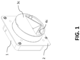
- an exhaust duct 1 comprising a support surface 2 and one acoustic baffle wall 3c having an acoustic baffle opening 4c.
- Acoustic baffle wall 3c is partially parallel, positioned on the outer facing side of support surface 2, and partially perpendicular to the air flow traveling through the exhaust duct. Behind the support surface 2, two more acoustic baffle walls 3a and 3b are present but not visibly shown in Figure 1 .
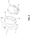
- FIG 2 shows an exploded view of the exhaust duct 1 of Figure 1 .
- the same elements are present but now acoustic baffle wall 3b is visible.
- Acoustic baffle wall 3b is completely parallel to the support surface 2 and is positioned on the inner facing side of support surface 2.
- Acoustic baffle wall 3b has an acoustic baffle opening 4b.
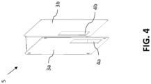
- Figure 4 shows at least a part of the acoustic baffle 5 having two successive acoustic baffle walls 3a and 3b, each having an opening 4a and 4b. It can be seen that the openings 4a and 4b are not directly aligned with each other, at least not horizontally, and are thus arranged in a staggered fashion.
- FIG 5 shows a cross-section of the exhaust duct 1 as shown in Figures 1 to 3 .
- the same elements are present again.
- all successive acoustic baffle walls 3a, 3b, and 3c can be seen, including acoustic baffle openings 4a, 4b, and 4c.
- acoustic baffle wall 3c has a geometrical shape that is only partly parallel to the support surface 2, and is partly arranged at an angle in relation to the air flow passing through the exhaust duct 2 via openings 4a, 4b, and 4c.
Landscapes
- Engineering & Computer Science (AREA)
- Chemical & Material Sciences (AREA)
- Combustion & Propulsion (AREA)
- Mechanical Engineering (AREA)
- General Engineering & Computer Science (AREA)
- Duct Arrangements (AREA)
Abstract
Providing an exhaust duct for a heat pump system, wherein the exhaust duct comprises a support surface and an acoustic baffle coupled to the support surface. The acoustic baffle reduces noise traveling with the air flow going through the exhaust duct.
Description
- The invention relates to an exhaust duct for a heat pump system, wherein the exhaust duct comprises a support surface and an acoustic baffle coupled to the support surface. The invention further relates to a heat pump system comprising such an exhaust duct.
- Heating of water in buildings, such as heating water of a central heating system or heating of water for domestic use, may be accomplished by means of a heat pump system. Such a heat pump system may either be a ground source heat pump (GSHP) system or an air source heat pump (ASHP) system. In a GSHP system, calories are exchanged between the ground, or ground water, and a fluid, the fluid in particular being air or water. The calories in the ground may be extracted by capturing calories in a water table or by circulating a water-based circuit in the ground. In an ASHP system calories are exchanged between the air and a fluid, in particular air or water.
- A heat pump system typically comprises at least one first heat exchanger for capturing calories from a first source, at least one second heat exchanger for transferring captured calories to a second destination fluid, and a refrigerant loop between both heat exchangers to transport the captured calories from the at least one first heat exchanger to the at least one second heat exchanger. The at least one first and second heat exchangers together with the refrigerant loop form, at least a part of, a heat exchanging circuit.
- The heat exchange achieved can be used to cool or heat the desired medium. Among the most commonly used circuits for a heat pump, the medium to be heated can be a heating water circuit and/or a sanitary water circuit.
- With the advent of flammable refrigerants, components are preferably grouped in refrigerant components and non-refrigerant components (e.g. hydraulics and electronics) where both groups are preferably separated for safety reasons. Furthermore, while leakage of any of the refrigerant components is prevented as much as possible, there will always remain a slight chance of refrigerant leakage. As the refrigerant under regular room temperature and pressure is in a gaseous phase, this will create a fairly dense gas cloud within the heat pump system. With all sorts of electrical components within the heat pump system and the refrigerant being flammable, there is a risk of ignition and explosion of the refrigerant. Any such risk has to be mitigated.
- Said risk may be mitigated by expelling any leaked refrigerant out of, and away from, the heat pump system by means of an exhaust duct. By using an exhaust duct, any leaked refrigerant may escape through the exhaust duct away from the heat pump system.
- Such an opening, however, will allow noises generated within the heat pump system to travel directly into the environment of the heat pump system. For instance, noise from the compressor may travel via the exhaust duct into the surroundings of the heat pump system. Similarly, any other component may generate unwanted noise within the heat pump system that could escape through the exhaust duct into the environment.
- Additionally, a fan may be used to expel the leaked refrigerant. By using a brushless motor exhaust fan, any leaked refrigerant is forced out and away from the heat pump system in a safe and quick way. However, as the air flow will be disturbed by the fan even more noise will be created.
- It is therefore desired to reduce the amount of noise, generated by any of the components within the heat pump system and/or of an exhaust fan, through the exhaust duct.
- The object of the invention is obtained by providing an exhaust duct for a heat pump system, wherein the exhaust duct comprises a support surface perpendicular to the direction of the air flow and an acoustic baffle coupled to the support surface, wherein the acoustic baffle comprises at least two successive walls arranged at an angle to the direction of the air flow, wherein the at least two successive walls each have at least one opening wherein each opening is not in direct alignment with the other opening, thereby forming at least two successive openings which are staggered from each other.
- The exhaust duct allows air to pass through from the inside of the heat pump system to the outside of the heat pump system. In case of a refrigerant leak, the leaked refrigerant is expelled outside of the heat pump through said exhaust duct. The exhaust duct comprises a support surface to allow the exhaust duct to be attached to the heat pump system. The exhaust duct has a general opening through which the air may flow. The exhaust duct may also comprise a guiding surface for attaching an air duct to the exhaust duct. The air duct attached to the guiding surface may be any tube, pipe or channel suitable to be used as an air duct. The guiding surface may be situated perpendicular to the support surface. The guiding surface may be straight or tapered.
- The acoustic baffle reduces noise traveling via the air though the exhaust duct. The at least two successive walls may be arranged at any angle other than parallel to the direction of the air flow. As such, the air flow will hit the walls and the sound waves traveling via the air flow will bounce of the wall reducing the intensity and distance of the sound wave. By providing an opening in each wall, air flow may still continue to flow. By not directly aligning each opening, thus forming a staggered pattern of the openings, the air flow can still continue to flow but the sound waves traveling via the air flow will further bounce off and gradually further decrease in intensity and distance travelled. As such, the acoustic baffle absorbs the sound waves and thus reduces the noise traveling though the exhaust duct and thereby achieves the object of the invention.
- In an embodiment, the acoustic baffle is situated between the support surface of the exhaust duct and the inside of a heat pump system, between the support surface of the exhaust duct and the outside of the heat pump system, or a combination thereof. When situated between the support surface and the inside of the heat pump, the acoustic baffle may reduce noise when the air flow is still inside the heat pump system. The acoustic baffle may be for instance positioned closer to a compressor inside the heat pump system and thus cover the noise generated by the compressor. When situated on between the support surface and the outside of the heat pump, the acoustic baffle may also act as a barrier for physical objects to be inserted into the heat pump system. For instance, the acoustic baffle may thus obstruct a user to accidentally insert a finger. When situated between the support surface and both the inside and outside of the heat pump, both advantages can be realized. This can be achieved by, for instance, having one of the successive walls to be situated between the support surface and the inside of the heat pump system and the other successive wall between the support surface and the outside of the heat pump system.
- In an embodiment, the at least two successive walls are parallel to each other. When the at least two successive wall are parallel to each other, the sound waves may bounce back and forth between both walls until their intensity and distance is reduced.
- In an embodiment, the at least two successive walls are arranged at an angle of 70° to 90° in relation to the direction of the air flow. By arranged both walls at said angle, the air flow effectively hits the walls and thus the sound waves are properly bounced off the walls.
- In an embodiment, each opening has a different shape or size. The openings may have any shape or size suitable to allow air flow to pass through the opening. The opening may, for instance, be rectangular, circular, triangular or any random shape.
- In an embodiment, each opening has a surface area of at least 120 mm2. By having an opening with a surface area of at least 120 mm2, sufficient air flow can pass through the opening.
- In an embodiment, each opening is situated in the bottom half of each wall. In case of a leakage of refrigerant, the refrigerant gas will mix with the air flow. As the refrigerant is heavier, denser, than air, it will naturally flow lower than the air. By providing the openings in the bottom half of each wall, the evacuation of the refrigerant is carried out in an optimal way and prevents the accumulation of flammable refrigerant in the heat pump unit. As the refrigerant is heavier than air, it will accumulate from the bottom of the unit to a height corresponding to the lowest point of the opening. Placing this opening at the bottom of the walls limits the accumulation and facilitates extraction.
- In an embodiment, each opening is situated at a height within 200 mm of the base of the heat pump system. This is the distance between the lowest point of the opening and the base of the heat pump system. Upon a leakage, leaked refrigerant can only build-up up to 200 mm in height between both points. Any kind of electronics, that could potentially be an ignition point, situated in the same compartment could then be positioned well above this area to prevent ignition of the leaked refrigerant.
- In an embodiment, each opening is situated at a height within 200 mm of a mounting surface for a compressor of the heat pump system. This is the distance between the lowest point of the opening and the mounting surface of the compressor. Upon a leakage, leaked refrigerant can only build-up up to 200 mm in height between both points. Any kind of electronics, that could potentially be an ignition point, situated in the same compartment could then be positioned well above this area to prevent ignition of the leaked refrigerant.
- In an embodiment, a sound absorbing material is attached to each wall. To even further reduce noise, any suitable acoustic foam or insulation material may be attached to each wall to absorb the sound waves traveling through the air flow.
- In an embodiment, a sound absorbing material is positioned near at least one wall. For example, a piece of sound absorbing material is positioned between two walls to further reduce the noise.
- In an embodiment, the walls of the acoustic baffle are made of panels of fine thickness in relation to their height and width. In particular, the acoustic baffle is made from folded sheet material, cut sheet material, molded material or a combination thereof, and the material used is rigid or deformable or a combination thereof. The acoustic baffle may thus be made from multiple panels of sheet material or can be molded as a single piece. Alternatively, some parts of the acoustic baffle can be made from panels of sheet material while other parts are made from molded material. When using molded material, said material may be formed using for instance injection molding or 3D printing.
- In an embodiment, the material used is metal, plastic, foam, or a combination thereof.
- In an aspect of the invention, an assembly for heating water in a building, in particular a heat pump system, is provided wherein the assembly comprising an exhaust duct according to any of the embodiments as disclosed above.
- In an embodiment of the aspect of the invention, the exhaust duct is positioned between a compressor situated within the assembly and the external surface of the assembly.
- In the figures, the subject-matter of the invention is schematically shown, wherein identical or similarly acting elements are usually provided with the same reference signs.
- Figure 1
- shows a schematic representation of an exhaust duct according to the present invention.
- Figure 2
- shows a schematic representation of an exhaust duct according to the present invention.
- Figure 3
- shows a schematic representation of an exhaust duct according to the present invention.
- Figure 4
- shows a schematic representation of two acoustic baffle walls according to the present invention.
- Figure 5
- shows a cross-sectional representation of an exhaust duct according to the present invention.
- With reference to
Figure 1 , anexhaust duct 1 is shown comprising asupport surface 2 and oneacoustic baffle wall 3c having anacoustic baffle opening 4c.Acoustic baffle wall 3c is partially parallel, positioned on the outer facing side ofsupport surface 2, and partially perpendicular to the air flow traveling through the exhaust duct. Behind thesupport surface 2, two moreacoustic baffle walls Figure 1 . -
Figure 2 shows an exploded view of theexhaust duct 1 ofFigure 1 . The same elements are present but nowacoustic baffle wall 3b is visible.Acoustic baffle wall 3b is completely parallel to thesupport surface 2 and is positioned on the inner facing side ofsupport surface 2.Acoustic baffle wall 3b has anacoustic baffle opening 4b. - In
Figure 3 , thesame exhaust duct 1 is shown as inFigure 1 but from a different angle. Again the same elements are present, but nowacoustic baffle wall 3a is visible.Acoustic baffle wall 3a is also completely parallel to thesupport surface 2 and also positioned on the inner facing side ofsupport surface 2.Acoustic baffle wall 3a has anacoustic baffle opening 4a. -
Figure 4 shows at least a part of theacoustic baffle 5 having two successiveacoustic baffle walls opening openings -
Figure 5 shows a cross-section of theexhaust duct 1 as shown inFigures 1 to 3 . The same elements are present again. Now, all successiveacoustic baffle walls acoustic baffle openings acoustic baffle wall 3c has a geometrical shape that is only partly parallel to thesupport surface 2, and is partly arranged at an angle in relation to the air flow passing through theexhaust duct 2 viaopenings -
- 1
- exhaust duct
- 2
- support surface
- 3a, 3b, 3c
- acoustic baffle wall
- 4a, 4b, 4c
- acoustic baffle opening
- 5
- acoustic baffle
Claims (15)
- An exhaust duct (1) for a heat pump system, wherein the exhaust duct (1) comprises:- a support surface (2) perpendicular to the direction of the air flow; and- an acoustic baffle (5) coupled to the support surface (2);wherein the acoustic baffle (5) comprises at least two successive walls (3a, 3b, 3c) arranged at an angle to the direction of the air flow, wherein the at least two successive walls (3a, 3b, 3c) each have at least one opening (4a, 4b, 4c) wherein each opening (4a, 4b, 4c) is not in direct alignment with the other opening (4a, 4b, 4c), thereby forming at least two successive openings (4a, 4b, 4c) which are staggered from each other.
- The exhaust duct (1) according to claim 1, wherein the acoustic baffle (1) is situated between the support surface (2) of the exhaust duct (1) and the inside of a heat pump system, between the support surface (2) of the exhaust duct (1) and the outside of the heat pump system, or a combination thereof.
- The exhaust duct (1) according to any of the preceding claims, wherein the at least two successive walls (3a, 3b, 3c) are parallel to each other.
- The exhaust duct (1) according to any of the preceding claims, wherein the at least two successive walls (3a, 3b, 3c) are arranged at an angle of 70° to 90° in relation to the direction of the air flow.
- The exhaust duct (1) according to any of the preceding claims, wherein each opening (4a, 4b, 4c) has a different shape or size.
- The exhaust duct (1) according to any of the preceding claims, wherein each opening (4a, 4b, 4c) has a surface area of at least 120 mm2.
- The exhaust duct (1) according to any of the preceding claims, wherein each opening (4a, 4b, 4c) is situated in the bottom half of each wall (3a, 3b, 3c).
- The exhaust duct (1) according to any of the preceding claims, wherein each opening (4a, 4b, 4c) is situated at a height within 200 mm of the base of the heat pump system.
- The exhaust duct (1) according to any of the preceding claims, wherein each opening (4a, 4b, 4c) is situated at a height within 200 mm of a mounting surface for a compressor of the heat pump system..
- The exhaust duct (1) according to any of the preceding claims, wherein a sound absorbing material is attached to each wall (3a, 3b, 3c).
- The exhaust duct (1) according to any of the preceding claims, wherein a sound absorbing material is positioned near at least one wall (3a, 3b, 3c).
- The exhaust duct (1) according to any of the preceding claims, wherein the acoustic baffle (5) is made from folded sheet material, cut sheet material, molded material or a combination thereof, and wherein the material used is rigid, deformable or a combination thereof..
- The exhaust duct (1) according to claim 12, wherein the material used is metal, plastic, foam, or a combination thereof.
- An assembly for heating water in a building, in particular a heat pump system, wherein the assembly comprising an exhaust duct (1) according to any of the preceding claims.
- The assembly according to claim 14, wherein the exhaust duct (1) is positioned between a compressor situated within the assembly and the external surface of the assembly.
Priority Applications (15)
| Application Number | Priority Date | Filing Date | Title |
|---|---|---|---|
| EP22199451.0A EP4350243A1 (en) | 2022-10-04 | 2022-10-04 | An acoustic baffle for an exhaust duct of a heat pump system |
| PCT/EP2023/063553 WO2023232508A1 (en) | 2022-05-30 | 2023-05-22 | An acoustic baffle for an exhaust duct of a heat pump system |
| PCT/EP2023/063551 WO2023232506A1 (en) | 2022-05-30 | 2023-05-22 | An air duct for a heat pump system |
| PCT/EP2023/063548 WO2023232504A1 (en) | 2022-05-30 | 2023-05-22 | Enclosure for a heat pump |
| EP23728690.1A EP4532994A1 (en) | 2022-05-30 | 2023-05-22 | Enclosure for a heat pump |
| PCT/EP2023/063546 WO2023232502A1 (en) | 2022-05-30 | 2023-05-22 | A mounting tray for holding heat pump components |
| PCT/EP2023/063547 WO2023232503A1 (en) | 2022-05-30 | 2023-05-22 | Enclosure for a heat pump |
| PCT/EP2023/063550 WO2023232505A1 (en) | 2022-05-30 | 2023-05-22 | Electronic component box for a heat pump system |
| PCT/EP2023/063554 WO2023232509A1 (en) | 2022-05-30 | 2023-05-22 | Heat pump unit, assembly of a heat pump unit and a tank and a method of installing a heat pump unit and a tank |
| EP23728688.5A EP4532997A1 (en) | 2022-05-30 | 2023-05-22 | A mounting tray for holding heat pump components |
| EP23723987.6A EP4532999A1 (en) | 2022-05-30 | 2023-05-22 | An air duct for a heat pump system |
| EP23728691.9A EP4532992A1 (en) | 2022-05-30 | 2023-05-22 | Electronic component box for a heat pump system |
| PCT/EP2023/063545 WO2023232501A1 (en) | 2022-05-30 | 2023-05-22 | An assembly of a housing and a drawer for heating water in a building |
| EP23728693.5A EP4532990A1 (en) | 2022-05-30 | 2023-05-22 | Heat pump unit, assembly of a heat pump unit and a tank and a method of installing a heat pump unit and a tank |
| EP23728692.7A EP4532993A1 (en) | 2022-05-30 | 2023-05-22 | An acoustic baffle for an exhaust duct of a heat pump system |
Applications Claiming Priority (1)
| Application Number | Priority Date | Filing Date | Title |
|---|---|---|---|
| EP22199451.0A EP4350243A1 (en) | 2022-10-04 | 2022-10-04 | An acoustic baffle for an exhaust duct of a heat pump system |
Publications (1)
| Publication Number | Publication Date |
|---|---|
| EP4350243A1 true EP4350243A1 (en) | 2024-04-10 |
Family
ID=83593925
Family Applications (1)
| Application Number | Title | Priority Date | Filing Date |
|---|---|---|---|
| EP22199451.0A Withdrawn EP4350243A1 (en) | 2022-05-30 | 2022-10-04 | An acoustic baffle for an exhaust duct of a heat pump system |
Country Status (1)
| Country | Link |
|---|---|
| EP (1) | EP4350243A1 (en) |
Citations (6)
| Publication number | Priority date | Publication date | Assignee | Title |
|---|---|---|---|---|
| GB2293234A (en) * | 1994-09-15 | 1996-03-20 | Airflow | Ventilator |
| WO2005073640A1 (en) * | 2004-01-28 | 2005-08-11 | Takayasu Co., Ltd. | Method of reducing noise of air blowing duct |
| CN207123049U (en) * | 2017-03-07 | 2018-03-20 | 南京大学建筑规划设计研究院有限公司 | A kind of noise reduction spout plenum chamber |
| CN213514137U (en) * | 2020-10-31 | 2021-06-22 | 深圳市西谷制冷设备有限公司 | Vertical air conditioner cabinet |
| CN215215286U (en) * | 2021-07-28 | 2021-12-17 | 清华大学 | Ventilating duct silencer suitable for underground environment |
| CN217109888U (en) * | 2022-04-02 | 2022-08-02 | 李玲燕 | Pipeline type silencing and air interchanging device |
-
2022
- 2022-10-04 EP EP22199451.0A patent/EP4350243A1/en not_active Withdrawn
Patent Citations (6)
| Publication number | Priority date | Publication date | Assignee | Title |
|---|---|---|---|---|
| GB2293234A (en) * | 1994-09-15 | 1996-03-20 | Airflow | Ventilator |
| WO2005073640A1 (en) * | 2004-01-28 | 2005-08-11 | Takayasu Co., Ltd. | Method of reducing noise of air blowing duct |
| CN207123049U (en) * | 2017-03-07 | 2018-03-20 | 南京大学建筑规划设计研究院有限公司 | A kind of noise reduction spout plenum chamber |
| CN213514137U (en) * | 2020-10-31 | 2021-06-22 | 深圳市西谷制冷设备有限公司 | Vertical air conditioner cabinet |
| CN215215286U (en) * | 2021-07-28 | 2021-12-17 | 清华大学 | Ventilating duct silencer suitable for underground environment |
| CN217109888U (en) * | 2022-04-02 | 2022-08-02 | 李玲燕 | Pipeline type silencing and air interchanging device |
Similar Documents
| Publication | Publication Date | Title |
|---|---|---|
| EP4532993A1 (en) | An acoustic baffle for an exhaust duct of a heat pump system | |
| US10928096B2 (en) | Environmental control unit including noise reduction features | |
| JP6501908B2 (en) | Outdoor unit | |
| CN1329638C (en) | compressor enclosure | |
| JP6399238B2 (en) | Air conditioner floor-standing indoor unit | |
| US9328965B2 (en) | Heat exchanger of air conditioning device including a refrigerant path arranged downstream of other refrigerant paths relative to airflow direction | |
| JPWO2013094082A1 (en) | Outdoor unit and refrigeration cycle apparatus including the outdoor unit | |
| KR20210106142A (en) | Air conditioner and control method thereof | |
| JP6388734B2 (en) | Outdoor unit of refrigeration cycle equipment | |
| US20120108160A1 (en) | Heating, ventilating, air conditioning, and refrigeration noise reduction system | |
| ES2927116T3 (en) | hole for air conditioner | |
| JP3107604U (en) | Air conditioner outdoor unit noise reduction structure | |
| CN109073249A (en) | Heat source unit | |
| KR102620355B1 (en) | Air conditioner | |
| JP6203112B2 (en) | Air conditioner outdoor unit | |
| US11248856B2 (en) | Refrigeration apparatus | |
| CN113518885A (en) | Outdoor unit for air conditioner and air conditioner | |
| KR20170082363A (en) | Air conditioner indoor unit | |
| JP7019097B2 (en) | Outdoor unit of air conditioner | |
| JP2014240713A (en) | Outdoor unit for air conditioner | |
| EP3339778B1 (en) | Heat rejection system for a condenser of a refrigerant loop within an appliance | |
| WO2018025325A1 (en) | Outdoor unit, air conditioning device, and method for manufacturing outdoor unit handle | |
| CN207779203U (en) | Refrigeration cycle device | |
| JP7086269B2 (en) | Indoor unit | |
| JP7146081B2 (en) | indoor unit of air conditioner |
Legal Events
| Date | Code | Title | Description |
|---|---|---|---|
| PUAI | Public reference made under article 153(3) epc to a published international application that has entered the european phase |
Free format text: ORIGINAL CODE: 0009012 |
|
| STAA | Information on the status of an ep patent application or granted ep patent |
Free format text: STATUS: THE APPLICATION HAS BEEN PUBLISHED |
|
| AK | Designated contracting states |
Kind code of ref document: A1 Designated state(s): AL AT BE BG CH CY CZ DE DK EE ES FI FR GB GR HR HU IE IS IT LI LT LU LV MC ME MK MT NL NO PL PT RO RS SE SI SK SM TR |
|
| STAA | Information on the status of an ep patent application or granted ep patent |
Free format text: STATUS: THE APPLICATION IS DEEMED TO BE WITHDRAWN |
|
| 18D | Application deemed to be withdrawn |
Effective date: 20241011 |