EP4350189B1 - Verfahren zum verbinden von ausgekleideten rohren und zugehörige vorrichtung - Google Patents
Verfahren zum verbinden von ausgekleideten rohren und zugehörige vorrichtung Download PDFInfo
- Publication number
- EP4350189B1 EP4350189B1 EP23193710.3A EP23193710A EP4350189B1 EP 4350189 B1 EP4350189 B1 EP 4350189B1 EP 23193710 A EP23193710 A EP 23193710A EP 4350189 B1 EP4350189 B1 EP 4350189B1
- Authority
- EP
- European Patent Office
- Prior art keywords
- pipe
- fit
- sleeve
- liner
- pipes
- Prior art date
- Legal status (The legal status is an assumption and is not a legal conclusion. Google has not performed a legal analysis and makes no representation as to the accuracy of the status listed.)
- Active
Links
Images


Classifications
-
- F—MECHANICAL ENGINEERING; LIGHTING; HEATING; WEAPONS; BLASTING
- F16—ENGINEERING ELEMENTS AND UNITS; GENERAL MEASURES FOR PRODUCING AND MAINTAINING EFFECTIVE FUNCTIONING OF MACHINES OR INSTALLATIONS; THERMAL INSULATION IN GENERAL
- F16L—PIPES; JOINTS OR FITTINGS FOR PIPES; SUPPORTS FOR PIPES, CABLES OR PROTECTIVE TUBING; MEANS FOR THERMAL INSULATION IN GENERAL
- F16L13/00—Non-disconnectable pipe joints, e.g. soldered, adhesive, or caulked joints
- F16L13/02—Welded joints
- F16L13/0254—Welded joints the pipes having an internal or external coating
- F16L13/0263—Welded joints the pipes having an internal or external coating having an internal coating
-
- F—MECHANICAL ENGINEERING; LIGHTING; HEATING; WEAPONS; BLASTING
- F16—ENGINEERING ELEMENTS AND UNITS; GENERAL MEASURES FOR PRODUCING AND MAINTAINING EFFECTIVE FUNCTIONING OF MACHINES OR INSTALLATIONS; THERMAL INSULATION IN GENERAL
- F16L—PIPES; JOINTS OR FITTINGS FOR PIPES; SUPPORTS FOR PIPES, CABLES OR PROTECTIVE TUBING; MEANS FOR THERMAL INSULATION IN GENERAL
- F16L58/00—Protection of pipes or pipe fittings against corrosion or incrustation
- F16L58/02—Protection of pipes or pipe fittings against corrosion or incrustation by means of internal or external coatings
- F16L58/04—Coatings characterised by the materials used
- F16L58/10—Coatings characterised by the materials used by rubber or plastics
- F16L58/1009—Coatings characterised by the materials used by rubber or plastics the coating being placed inside the pipe
- F16L58/1018—Coatings characterised by the materials used by rubber or plastics the coating being placed inside the pipe the protective layer being fixed by means of anchoring devices
-
- F—MECHANICAL ENGINEERING; LIGHTING; HEATING; WEAPONS; BLASTING
- F16—ENGINEERING ELEMENTS AND UNITS; GENERAL MEASURES FOR PRODUCING AND MAINTAINING EFFECTIVE FUNCTIONING OF MACHINES OR INSTALLATIONS; THERMAL INSULATION IN GENERAL
- F16L—PIPES; JOINTS OR FITTINGS FOR PIPES; SUPPORTS FOR PIPES, CABLES OR PROTECTIVE TUBING; MEANS FOR THERMAL INSULATION IN GENERAL
- F16L58/00—Protection of pipes or pipe fittings against corrosion or incrustation
- F16L58/18—Protection of pipes or pipe fittings against corrosion or incrustation specially adapted for pipe fittings
- F16L58/181—Protection of pipes or pipe fittings against corrosion or incrustation specially adapted for pipe fittings for non-disconnectable pipe joints
Definitions
- the present invention relates to the field of hydrocarbon service, and in particular pipelines comprising liners for corrosion prevention. More specifically, the present invention relates to improvements to methods of joining lined pipes that increase the integrity, reliability and utility of the resulting lined pipelines, as well as reducing complexity and simplifying fabrication and/or construction.
- British Patent Number GB 2,186,340 in the name of British Gas, discloses a method of lining a buried gas, water or sewage pipe using a synthetic resin liner having an external diameter greater than the internal diameter of the pipe.
- the liner is heated, pulled through a die which reduces its external diameter and then through the pipe to be lined. Thereafter the liner is pressurised such that it expands into contact with the internal wall of the pipe.
- United States Patent Number US 6,240,612 also in the name of British Gas, discloses a similar method of lining installed pipework in which the external diameter of a liner made from a memory retaining plastics material is reduced by up to 15% by pulling the liner through a die at ambient temperature. After pulling through the pipework the liner is allowed to expand within the pipework by relaxation of pulling tension followed by memory induced expansion at ambient temperature and pressure. This expansion into contact with the internal wall of the pipe is generally referred to as "reversion".
- British Patent Number GB2298256B again in the name of British Gas, describes a method of joining lined pipes in which a tubular carbon steel fitting is welded to corresponding ends of the pipes to be joined.
- the inner surface of each fitting is provided with a corrosion resistant alloy (CRA) cladding and a series of annular grooves and castellations.
- the pipes (and fittings welded thereto) are then lined with a polyethylene liner, for example using the above-mentioned reduction (via a swaging die), insertion and reversion technique.
- a compression ring is then inserted into the ends of each fitting such that the respective liners are forced into the annular grooves and against the castellations.
- the fittings are then welded together by an annular girth weld. This is known in the art as a WeldLink connection.
- the improved pipe liner comprises a metallic barrier layer, which prevents permeation through the liner, sandwiched between an inner polymer pipe and an outer polymer pipe.
- the inner polymer pipe is porous which permits free movement of gas between the internal bore of a lined pipe and the barrier layer, so as to prevent accumulation of gases anywhere in the lined pipe, while ensuring that gases do not permeate to, and damage, the host pipe.
- This intentional permission of free movement through the inner polymer pipe is not to be confused with the gradual and eventual permeation that occurs, particularly under pressure, in conventional liners or even in conventional barrier pipe. As explained above, such permeation is entirely undesirable and can have catastrophic consequences in service.
- the method further comprises inserting the first liner in the first pipe and inserting the second liner in the second pipe.
- inserting the liner comprises reducing the external diameter of the liner and pulling the liner through the pipe, before allowing the liner to revert.
- reducing the diameter of the liner comprises pulling the liner through a swaging die or one or more rollers.
- reducing the diameter of the liner comprises folding or otherwise deforming the cross-section of the liner.
- the method comprises trimming the liner back to substantially coincide with an insertion rim of the respective pipe.
- the end of the liner may therefore be in alignment with the insertion rim or may extend slightly beyond the insertion rim.
- first and second pipes may be lined pipes.
- a lined pipe is a pipe which has already been lined and comprises (at least) a host pipe and a liner.
- the method Prior to inserting the fit-up sleeve, the method preferably comprises inserting first and second sealing rings within the first and second liners to force second portions of the first and second liners against corresponding second portions of the castellations.
- the method Prior to inserting the first and second sealing rings, the method preferably comprises temporarily reducing the outer diameter of the liners.
- One or more cooling jackets may be applied to external surfaces of the pipes before joining the pipes.
- the method comprises providing an overlap between the first and second liners and the first and second pipes.
- the first and second liners extend to insertion rims of the first and second pipes.
- the first end of the fit-up sleeve abuts the insertion rim of the first pipe and the second end of the fit-up sleeve abuts the insertion rim of the second pipe.
- the method comprises providing an o-ring or gasket between the fit-up sleeve and each of the insertion rims.
- the method optionally comprises providing an o-ring or gasket between each of the sealing rings and the fit-up sleeve.
- the method comprises welding the first pipe to the second pipe.
- the method comprises attaching a flange of the first pipe to a flange of the second pipe.
- the method comprises inserting a pin section of one of the first and second pipes into a box section of the other.
- inserting the second end of the fit-up sleeve into the second pipe to force the second liner against the second pipe comprises moving the first lined pipe towards the second lined pipe after inserting the first end of a fit-up sleeve into the first pipe.
- inserting the first end of the fit-up sleeve into the first pipe to force the first liner against the first pipe comprises moving the first lined pipe towards the second lined pipe after inserting the second end of the fit-up sleeve into the second pipe.
- moving the first lined pipe towards the second lined pipe may comprise making the mechanical connection.
- Making the mechanical connection may comprise tightening of one or more bolts or application of one or more clamps.
- the method comprises forming a plurality of castellations in internal surfaces of the first and second pipes.
- the plurality of castellations are formed in a corrosive resistant alloy cladding applied to the first and second pipes.
- the plurality of castellations are formed in the body of the first and second pipes.
- the sealing rings compress the liners sufficiently to render the inner polymer layers non-porous.
- the method comprises removing a section of the porous layer.
- the porous layers terminate at the edge or ends of the sealing rings.
- the porous layers terminate behind the sealing rings.
- the porous layer is removed by chemically dissolving the material of the porous layer.
- the porous layer is removed by cutting or peeling.
- the method comprises reducing the effectiveness of an adhesive layer between the porous layer and the barrier layer to aid in removal.
- the adhesive between the porous layer and the barrier layer, at least in the region to be removed, is selected or adapted to enable the inner porous layer to be peeled or otherwise removed from the barrier layer.
- the method comprises carrying out non-destructive testing of a welded pipe joint.
- the method comprises re-making the welded pipe joint responsive to determining that the pipe joint comprises an unacceptable weld.
- re-making the pipe joint comprises:
- cutting through the pipe joint comprises cutting through the fit-up sleeve, and removing the fit-up sleeve comprises removing portions of the fit up sleeve from the first and second pipes.
- cutting through the pipe joint and separating the first pipe from the second pipe comprises cutting out a section of the pipe joint containing the weld.
- the section is of a predetermined length.
- the replacement fit-up sleeve is shorter than the removed fit-up sleeve by the predetermined length.
- re-making the pipe joint comprises:
- cutting through the pipe joint and separating the first pipe from the second pipe comprises cutting out a section of the pipe joint containing the weld.
- the section is of a predetermined length.
- the second spacer rings are shorter than the first spacer rings by a length corresponding to the predetermined length (or size of the weld cut-out), or vice versa.
- Embodiments of the first aspect of the invention may comprise features corresponding to the preferred or optional features of any other aspect of the invention (or vice versa).
- a pipeline comprising:
- a lined pipe comprises (at least) a host pipe and a liner.
- the plurality of castellations are formed in a corrosive resistant alloy cladding applied to the first and second pipes.
- the plurality of castellations are formed in the body of the first and second pipes.
- the castellations project from the internal surfaces of the pipes.
- the internal surfaces of the pipes comprise a series of grooves. The series of grooves inevitably result in castellated surfaces.
- the fit-up sleeve forces first portions of the first and second liners against corresponding first portions or sets of the castellations.
- the first portions or sets of the castellations comprise a tapered inner diameter.
- the pipeline further comprises first and second sealing rings within the first and second liners which force second portions or sets of the first and second liners against corresponding second portions or sets of the castellations.
- the second portions or sets of the castellations comprise a constant inner diameter.
- the first and second portions or sets of the castellations comprise a continuous taper.
- first and second portions or sets of castellations are continuous.
- first and second portions or sets of castellations are axially separated.
- the fit-up sleeve comprises a substantially cylindrical central portion and first and second liner engaging portions.
- the first and second liner engaging portions are tapered.
- the outer diameter of the cylindrical central portion is greater than the outer diameter of each of the first and second liner engaging portions. In this way, the fit-up sleeve is provided with first and second shoulders.
- the pipeline further comprises insulation between the first and second liners and the corresponding first and second host pipes at the locations of the joints between the liners and the pipes.
- the first and second pipes comprise insertion rims.
- the ends of the liners substantially coincide with the insertion rims.
- a first shoulder of the fit-up sleeve abuts the insertion rim of the first pipe and a second shoulder of the fit-up sleeve abuts the insertion rim of the second pipe.
- the pipeline further comprises an o-ring or gasket between the fit-up sleeve and each of the insertion rims, preferably between the shoulders and respective insertion rims.
- the pipeline further comprises an o-ring or gasket between each of the sealing rings and the fit-up sleeve.
- the fit-up sleeve comprises the sealing rings.
- the pipeline further comprises a spacer ring between the fit-up sleeve and each of the insertion rims, preferably between the shoulders and respective insertion rims.
- the first pipe is welded to the second pipe.
- the first and second pipes each comprise a flange and the flanges are joined together.
- the first pipe comprises a pin section and the second pipe comprises a box section, or vice versa.
- the liners comprise an inner polymer pipe and a barrier layer surrounding the inner polymer pipe, wherein the inner polymer pipe is porous.
- the liners further comprise an outer polymer pipe surrounding the barrier layer.
- the outer polymer pipe is non-porous.
- the sealing rings compress the liners sufficiently to render the inner polymer layer non-porous.
- the porous layers of each liner terminate at the edge or ends of the sealing rings, or the porous layers terminate behind the sealing rings, such that the first and second liner-engaging portions of the fit-up sleeve contact the barrier layer.
- Embodiments of the second aspect of the invention may comprise features corresponding to the preferred or optional features of any other aspect of the invention (or vice versa).
- a pipeline may be produced by providing a plurality of lined pipes and joining the lined pipes in accordance with the method of the first aspect.
- the liner may be folded or otherwise deformed into an H-, U- or C-shaped cross-section, inserted into the host pipe, and then allowed or caused to return to its original shape by application of heat and/or pressure for example. This is sometimes referred to as close-fit lining or fold and form lining.
- Figure 1 shows a cross-section through a lined pipe 101 which comprises a carbon steel host pipe 103 and a liner 105.
- a carbon steel host pipe may be provided with corrosion resistance by installation of a polymer liner (using a reduction and reversion process) which remains in tight contact with the interior surface of the carbon steel host pipe.
- the internal bore of the lined pipe through which fluid is transported is indicated by reference numeral 102.
- the liner 105 differs from conventional liners in at least one key detail.
- the liner 105 is a multilayer liner and comprises an outer polymer layer, polymer pipe 105B, which is bonded to barrier layer 111 using an adhesive (not shown). It is the outer polymer pipe 105B which contacts the host pipe 103 after the liner 105 has reverted. It will be understood that the outer polymer pipe is substantially cylindrical, hence describing same as a "pipe”. It might equivalently be termed an outermost polymer layer of the liner.
- the multilayer liner further comprises an inner polymer pipe 105A which is porous, and is bonded to the barrier layer 111, on the opposite side of the barrier layer 111 from the outer polymer pipe 105B, using a (preferably porous) adhesive (again, not shown).
- a (preferably porous) adhesive (again, not shown).
- the porous pipe 105A is also substantially cylindrical, hence describing same as a "pipe”.
- the purpose of the porous pipe 105A is expressly to permit the passage of gas (or liquid) through the inner layer (or layers) of the liner 105, between the internal bore 102 of the lined pipe 101 and the barrier layer 111 and vice versa.
- the porous pipe 105A comprises a polymer material and purposely has a plurality of pores or interstices which permit the passage of gas (or liquid), in contrast with conventional polymer liners which are substantially solid (i.e. do not permit the passage of gas or liquid). While gas or liquid, particularly under pressure, might gradually and eventually permeate through a conventional liner, the skilled person will realise that this is not at all desirable and is potentially catastrophic.
- the liner 105 prevents permeation and furthermore does so without moving the risk from an annulus between a liner and a host pipe to an interface between a barrier layer and an inner polymer pipe (for example, of a barrier pipe).
- a barrier layer comprises a CRA material
- the pipes to be joined have been (or will be, as discussed below) lined using a reduction and reversion process, such as Swagelining ® or roll-down. It will however be understood that other methods of lining a pipe with such a liner are possible (as intimated above with examples).
- the following description of a process of joining sections of lined pipe in a "cut to length" operation allows certain preferred and optional features of the methods and apparatus to be understood in context. Note that these methods are applicable whether the liner is a single layer liner or multilayer liner, and/or whether or not the multilayer liner comprises a porous inner pipe or a barrier layer. It is also discussed below how certain steps may be omitted in different operations; a "cut to length" operation being one specific operation which comprises steps not necessary in other operations (as will become clear).
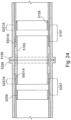
- Figure 2 indicates at A the extent of the fabricated and lined length of the pipe 101, at B the measured length for tie in weld termination, and at C the intended location of the connection between the pipe 101 and associated fitting (not shown but indicated by reference numeral 151 in subsequent Figures).
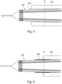
- Figure 3 shows the pipe 101 following a first cut through the host pipe 103 to the liner 105, and a rough cut of the liner 105 leaving a relatively short (for example 500 mm) length of liner 105 protruding from the host pipe 103.
- a mechanical towing head 121 is attached to the end of the liner 105 as shown in Figure 4 .
- the towing head 121 is then tensioned which extends the liner 105 axially and consequently results in a reduction in the outer diameter of the liner 105, thus producing an annular space 123 between the liner 105 and the host pipe 103 as shown in Figure 5 .
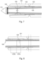
- the host pipe 103 is then cut to the target length C as shown in Figure 6 and an insulation sleeve 125 is inserted into the annular space 123.
- a single cut for example to location C, could be made without first making a cut to location B, particularly if the liner 105 is not expected to move when the host pipe is cut 103 (if there is a high level of residual strain the liner 105 might expand).
- the pipe 101 could instead be provided with a portion of the liner 105 already protruding beyond the end of the host pipe 103, for example by lining the pipe 101 with an oversized liner 105 or by cutting the host pipe 103 in an earlier preparatory step, ready for attachment of the mechanical towing head 121 and subsequent joining steps as follow.
- Tubular fitting 151 which comprises a carbon steel body 153 with an internal corrosion resistant alloy cladding 155, is positioned over the liner 105 and welded to the host pipe 103 using an annular girth weld as shown in Figure 7 .
- the insulation sleeve 125 previously inserted between the liner 105 and the host pipe 103 protects the liner 105 during this step.
- the insulation sleeve 125 might be omitted if sufficient space can be provided between the liner 105 and the host pipe 103 or if the welding process can otherwise avoid heat damage to the liner 105.
- the insulation sleeve 125 could be removed after the welding step is carried out, but in this example it remains in place post-welding.
- cooling jackets may be wrapped around the host pipe in the vicinity of the weld to actively draw heat away and prevent damage to the liner.
- fitting 151 might alternatively be referred to as an extension or a pipe extension as it effectively extends the host pipe 103 as well as providing it with castellations (as described below). Also note that the fitting might be comprised entirely of corrosion resistant alloy or carbon steel.
- the inner surface of the fitting 151 is provided with a series of projections or castellations 157, further details of which will be discussed below.
- the castellations 157 define a series of corresponding grooves and as such the inner surface of the fitting 151 might, alternatively, be described as being provided with a series of grooves. In fact, instead of directly providing castellations (which project out from the inner surface of the fitting) the inner surface of the fitting might be provided with a series of grooves in the inner surface of the fitting which inevitably results in a castellated surface. It is preferred however that the castellations project from the internal diameter of the fitting.
- the castellations 157 comprise a first castellation section 157A and a second castellation section 157B.
- the first castellation section 157A has a substantially constant inner diameter whereas the second castellation section 157B tapers outwardly towards the distal end of the fitting 151 (with respect to the host pipe 103) from an inner diameter similar or corresponding to that of the first castellation section 157A to a larger inner diameter closer to the inner diameter of the body 153 of the fitting 151.
- a sealing ring 159 is inserted into the fitting 151, within the liner 105, which forces the liner 105 into contact with the first castellation section 157A. This serves to prevent subsequent movement of the liner 105 (should it be required) and provides a first seal. Note that the sealing ring 159 compresses all layers of the liner 105, including the porous layer which is compressed sufficiently to render it non-porous.
- the sealing ring 159 is formed from a corrosion resistant alloy but might be formed from a different material such as carbon steel with a corrosion-resistant coating
- the castellations might comprise a single section which is tapered in its entirety. That is, there is no section of constant inner diameter.
- the gradient of the single taper may increase towards the distal end of the fitting. This may not be necessary, for example if the sealing ring is tapered in the opposite sense.
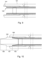
- Excess liner is then trimmed back as shown in Figure 9 such that the liner 105 terminates short of the ends of the fitting 151, in alignment with an insertion rim 161 (or extending slightly beyond), in this case provided by the internal corrosion resistant alloy cladding 155.
- a fit-up sleeve 163 is then inserted into the end of the liner 105.
- the fit-up sleeve 163 comprises a first liner engaging portion 165 which is tapered in the opposite sense to the taper of the second castellation section 157B. In this region the fit-up sleeve 163, and in particular the first liner engaging portion 165, forces the liner 105 into the castellations in the second castellation section 157B and provides a second seal.
- the fit-up sleeve 163 comprises a central portion 167 which is substantially cylindrical and has an outer diameter larger than that of the first liner engaging portion 165 so as to define a shoulder 168 which abuts the insertion rim 161 of the fitting 151 and creates an airtight seal. Accordingly, the depth to which the fit-up sleeve 163 is inserted can be controlled or pre-determined.
- the fit-up sleeve 163 is symmetrical and comprises a second liner engaging portion 169, corresponding to the first liner engaging portion 165, at the opposite end of the fit-up sleeve 163.
- O-rings or gaskets can be employed at the interfaces between, for example, the shoulders and the insertion rims, to improve the seals at these locations.
- O-ring or gasket sizes can be selected from a look up table based on the final dimensions and other parameters of the joint, for example gap sizes and/or the actual depth of the insertion rim following any necessary preparation of the fitting for welding. For example, "j" preparation for automatic welding or "v” preparation for manual welding will result in variability which can be compensated for using appropriately sized o-rings or gaskets.
- the sealing ring 159 could be dispensed with and the fit-up sleeve used alone.
- the first and second liner engaging portions of the fit-up sleeve might have the same axial extent as the corresponding castellations.
- the distal ends of the first and second liner engaging portions may comprise a first section of substantially constant outer diameter (at distal ends thereof) and a second section which tapers outwardly from the first section towards the central portion.
- the first section of substantially constant outer diameter would cooperate with the castellations of substantially constant inner diameter, and the tapered second section would cooperate with the tapered second castellation section.
- the second pipe 201 is prepared in a similar manner to the first 101 up to but before the point at which the fit-up sleeve 163 is inserted.
- the liner 205 of the second pipe 201 is forced against a first castellation section 257A of a second fitting 251 by a sealing ring 259, and the liner 205 terminates at a corresponding depth stop or insertion rim 261.
- the second pipe is stationary and the first pipe 101, terminated by the fitting 151 and fit-up sleeve 163, is pushed or otherwise moved towards the second pipe 201.
- the fit-up sleeve 163 is received in the second pipe 201 and further movement causes the second liner engaging portion 169 to force the liner 205 into the castellations in the second castellation section 257B.
- the depth stop or insertion rim 161 of the first fitting 151 acts against the shoulder 168 of the fit-up sleeve 163 as a ram to push the fit-up sleeve 163 into the liner 203.
- opposing shoulder 170 abuts corresponding insertion rim 261 of the second fitting 251, forming another airtight seal.
- fit-up sleeve 163 by having an internal diameter commensurate with the diameter of the bore 102 it can effectively act as a pigging sleeve which facilitates the transit of pigs over the resulting pipe joint.
- first pipe 101 (terminated by the fitting 151 and fit-up sleeve 163) could be stationary and the second pipe 201 instead pushed or otherwise moved towards the first pipe 101.
- annular girth weld can then be performed to join the fittings 151,251 together as shown in Figure 12 .
- the airtight seals provided at the abutments between insertion rims 161,261 and shoulders 168,170 prevent backdraughts and provide a boundary for a welding back purge, thus enabling CRA welding (necessitated by the use of a CRA cladding in the fittings 151,251) without the requirement for purging facilities within the closed pipeline.
- the relatively small volume of the annular space in the region of the weld (between the abutments) will be filled much more quickly than in normal back purged welding operations.
- the fittings may be wholly formed from carbon steel rather than having CRA cladding. In such an arrangement this necessity for CRA welding and the associated complications (such as back purging) are not a concern. It is envisaged that the fittings might be so formed regardless of whether the pipeline is intended for transporting corrosive species because there may be no risk of said corrosive species reaching the fittings because of a barrier in the liner, the seals formed by the sealing rings and the fit-up sleeve, and/or the seals between the shoulders of the fit-up sleeve and corresponding insertion rims. As mentioned below, there may also be provided o-rings or gaskets to supplement these seals.
- Figure 13 shows a joint between two lined pipes 1101 and 1201 created in a similar manner to that described above but with some key differences as shall now be described.
- the fittings 1151,1251 are machined from solid oversized carbon steel pipe; that is, there is no internal CRA cladding.
- the castellations 1157,1257 and the insertion rims 1161,1261 are formed directly in the carbon steel pipe.
- the fittings may be formed from any suitable material.
- o-rings 1173 and 1273 between insertion rims 1161,1261 and shoulders 1168,1170 (respectively).
- the o-rings could be replaced or supplemented with gaskets or the like.
- O-rings or gaskets may also (or alternatively) be provided between the sealing ring and the fit-up sleeve (as indicated by reference numerals 1175 and 1275) thus providing a further seal.
- the liners 1105,1205 comprise conventional polyethylene pipe; that is to say there is no barrier layer or porous inner layer.
- the pipeline illustrated might be deemed unsuitable for, say, sour hydrocarbon service (for which the previous arrangement would be particularly suited) but might be particularly well suited for water injection flowlines.
- Figure 14 shows an exploded view of a joint between two lined pipes 2101 and 2201, similar to the joint shown in Figure 13 but again with some key differences as shall now be described.
- the fittings 2151,2251 are machined from solid oversized carbon steel pipe.
- the castellations 2157,2257 are formed directly in the carbon steel pipe by creating a number of recesses.
- the fit-up sleeve 2163 is sized and shaped such that the leading ends of the fit-up sleeve 2163 touch the respective sealing rings 2159,2259.
- a copper backing strip 2181 to accommodate automatic welding of the fittings 2151,2251.
- the ends of the fittings are also provided with j-shaped bevels 2183 to accommodate narrow gap welding.
- the liners 2105,2205 comprise a barrier layer and porous inner layer, similar to the liner shown in Figures 1 to 12 . It is envisaged that the use of such liners will negate the need to use CRA cladding (the fittings in this embodiment comprised solely of carbon steel) even in the presence of very aggressive corrosive species, such as in sour hydrocarbon service. It will however be appreciated from the foregoing that the nature of the liner is irrelevant to the invention.
- one or more of the welds can be replaced with alternative means of joining tubular components.
- the fittings could be provided with flanges which are instead bolted or otherwise fastened together (see Figure 24 and brief discussion below).
- the action of bringing the flanges together by the tightening of bolts, application of a clamp (or clamps), or the like might remove the necessity to push the pipes (that is, the fittings on the ends of the pipes) together completely.
- the final stages of compressing the liner material between the fit-up sleeve and the castellations is achieved as the flanges are brought together.
- fittings could be attached to the ends of the respective pipes by flanged connections similar to that described briefly above.
- the fittings could still be welded together (when joining the pipes together) if required or desired.
- one of the fittings comprises a pin section and the other fitting comprises a box section to receive the pin section of the other.
- the box section comprises a plurality of internal grooves and/or projections and the pin section a plurality of corresponding external grooves and/or projections.
- the annular space between the pin section and the box section is pressurised (for example by injecting hydraulic fluid) so as to expand the box section.
- a clamp or a ram pushes (or pulls) the pin section fully into the box section, the pressure is reduced and the box shrinks onto the pin and the grooves and/or projections cooperate to provide a series of metal-to-metal seals.
- the clamping action may provide the final stage of compression between the fit-up sleeve and the respective liner.
- the pipes to be joined have been lined using a reduction and reversion process, such as Swagelining ® or roll-down, that results in a tight-fitting liner. It will also be understood that other methods of lining a pipe with a liner are possible, and this would include close-fit lining or fold and form lining as described briefly above.
- Figure 7 may illustrate the final step of such a process in which the first fitting 151 is welded to the first host pipe 103 before inserting the first liner 105 (i.e. the first pipe 101 is not initially a lined pipe), and the first liner 105 subsequently pulled through the first host pipe 103 and first fitting 151 (for example using a solid pulling head).
- the second pipe 201, to which the first pipe 101 is to be joined may also have been lined in this way, that is after the second fitting 251 has been joined to the second host pipe 203 (i.e. the second pipe 201 is not initially a lined pipe either).
- All the following steps may then be carried out as described above with reference to Figures 7 to 12 .
- the ends of the pipes themselves can be machined (or clad in CRA material and machined) to provide the desired internal profile (in which case any features described above in relation to fittings may be provided instead in the pipe; for example castellations, flanges or mechanical connections). Accordingly, it is possible to also omit the steps set out above and discussed with reference to Figures 7 (at least), and corresponding steps as they may relate to other arrangements described herein. Thus arrangements described herein form embodiments of the invention when the castellations are provided in internal surfaces of the pipes rather than in internal surfaces of fittings joined to the pipes.
- the subsequent steps of inserting the sealing ring ( Figure 8 ) and cutting back the liner to the depth stop or insertion rim ( Figure 9 ) could constitute the final steps of a lining process which produces a section of lined pipe ready to be joined, as required, to another like section of lined pipe by inserting a first end of a fit-up sleeve into one of the lined pipes, pushing a second end of the fit-up sleeve into the other lined pipe, and then joining the two lined pipes (or their respective fittings) together by welding or by a mechanical connection therebetween as intimated above.
- the sealing ring is inserted into the fitting within the liner so as to prevent subsequent movement of the liner (should it be required) and to provide a seal which prevents axial transit or permeation of liquid or gas along the porous layer in the region between the sealing ring and the respective fitting.
- the seal is formed by compressing all layers of the liner, and in particular the porous layer which is compressed sufficiently to render it non-porous.
- Another seal is provided by the fit-up sleeve which also compresses a subsequent portion of the liner against the fitting and a further seal may be provided by the optional provision of o-rings or gaskets between the fit-up sleeve and the sealing ring (as illustrated in Figure 13 ).
- Figure 15 corresponds to Figure 9 and this arrangement may share any or all features and steps leading up to this point with that arrangement (for example as described with reference to Figures 1 to 8 ).
- Figure 15 (similarly to Figure 9 ) shows that after insertion of the sealing ring 3159, the liner 3105 is trimmed back such that it terminates short of the ends of the fitting 3151, coincident with (or slightly proud of) an insertion rim 3161 formed by the castellated internal corrosion resistant alloy cladding 3155.
- a section of the porous layer 3105A is then removed such that the porous layer 3105A terminates at the edge or end of the sealing ring 3159 as shown in Figure 16 .
- the exact process by which the porous layer 3105A is removed will be dependent on the materials from which the liner 3105 is made (for example the material of the porous layer and/or the adhesive between the porous layer and the barrier layer 3111).
- One way in which the porous layer 3105A may be removed is by chemically dissolving the polymer material of the porous layer 3105A without damaging the barrier layer 3111.
- the porous layer 3105A may be mechanically removed, for example by cutting or by machining to reduce the thickness of the porous layer 3105A and subsequently peeling it away from the barrier layer 3111.
- the effectiveness of the adhesive between the porous layer 3105A and the barrier layer 3111 can be reduced, aiding removal of the porous layer 3105A, for example by application of heat or chemical means (such as a suitable acid composition).
- the adhesive (at least in this region) can be selected to enable the porous layer to be peeled away from the barrier layer.
- a fit-up sleeve 3163 is then inserted into the end of the liner 3105.
- the fit-up sleeve 163 comprises a first liner engaging portion 3165 which is tapered in the opposite sense to the taper of the second castellation section 3157B and the liner 3105 is compressed therebetween.
- the fit-up sleeve 3163, and in particular the first liner engaging portion 3165 is in direct contact with the now-exposed barrier layer 3111.
- the absence of the porous layer in this region means that any liquid or gas which transits or permeates past the sealing ring 3159 through the compressed porous layer vents directly back to the internal bore.
- the second pipe 3201 is prepared in a similar manner to the first 3101 up to but before the point at which the fit-up sleeve 3163 is inserted, including removing the porous layer 3205A up to the sealing ring 3259.
- the first pipe 3101 terminated by the fitting 3151 and fit-up sleeve 3163, is pushed or otherwise moved towards the second pipe 3201.
- the fit-up sleeve 3163 is received in the second pipe 3201 and further movement causes the liner 3205 to be compressed between second liner engaging portion 3169 and the second castellation section 3257B.
- the fit-up sleeve 3163 and in particular the second liner engaging portion 3169, is in direct contact with the now-exposed barrier layer 3211.
- the absence of the porous layer in this region means that any liquid or gas which transits or permeates past the sealing ring 3259 also vents directly back to the internal bore.
- An annular girth weld can then be performed to join the fittings 3151,3251 together, for example as described above with reference to Figure 12 .
- the porous layer 3105A may be terminated between the ends of the sealing ring such that the interface or termination resides behind the sealing ring 3159 (or between the sealing ring 3159 and the fitting 3151). In this way, the transition between the porous layer 3105A and the barrier layer 3111 may be sealed. This might be achieved by removing a suitable length of the porous layer 3105A prior to insertion of the sealing ring 3159, the sealing ring 3169 effectively extending between a portion of the liner 3105 where there is a porous layer 3105A present and where the barrier layer 3111 is exposed.
- the porous layer 3105A may be terminated at a location between the insertion rim 3161 and the sealing ring 3159 such that it resides behind the fit-up sleeve 3163 (or between the first liner engaging portion 3165 of the fit up sleeve 3163 and the fitting 3151).
- An additional benefit of the invention which overcomes significant disadvantages of prior art methods of joining lined pipe, is also realised when it is necessary to repair, or specifically re-make, the weld between the fittings.
- non-destructive testing is carried out on a weld to make sure it is acceptable for service. If it is not acceptable, but it can be repaired, then a repair is carried out and non-destructive testing carried out to make sure the repaired weld is acceptable for service. If the original or the repaired weld cannot be repaired, it is necessary to re-make the weld.
- Remaking welds with all existing weldable connectors is time consuming on the critical path and thereby significantly expensive and contains reasonable operational technical risk.
- the present invention negates the risk and the time taken to effect the re-weld and thereby significantly reduces the cost.
- the pipe joint may be cut through, the first and second fittings pulled apart and the fit-up sleeve removed.
- the skilled person will understand that in order to re-make the weld, it would be usual to cut out a section of the joint containing the weld. This might, for example, be a 30 mm section. In this case it would not be possible to use the same fit up sleeve when re-making the joint because the ends of the fittings would not meet; accordingly a shorter fit up sleeve (for example, 30 mm shorter), would be required to ensure proper fit up is maintained when the fittings are brought together and welded.
- Figures 19 to 23 illustrate a further alternative arrangement which incorporates a number of features specifically intended to facilitate repairing or re-making welds between the first and second fittings.
- Fit-up sleeves of various arrangements described above comprise a substantially cylindrical central portion of an outer diameter larger than that of the substantially conical liner engaging portions at either end thereof, providing shoulders which abut corresponding insertion rims of the fittings into which they are inserted. As intimated above, in this way the depth to which the fit-up sleeve is inserted can be controlled or pre-determined.
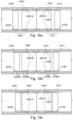
- Figure 19 corresponds to Figures 11 and 18 of arrangements described above and (a) shows a connector assembly ready for welding to create a joint between respective lined pipes.
- a pair of spacer rings 4501A of a first length A Located between the shoulders of the fit-up sleeve 4163 and the insertion rims 4161,4261 are a pair of spacer rings 4501A of a first length A.
- the weld is cut out and the fit-up sleeve 4163 and the spacer rings 4501A are removed.
- a pair of spacer rings 4501B of a second, shorter, length B are inserted and the fit-up sleeve 4163 re-inserted (b).
- the difference in length of spacer rings 4501B with respect to spacer rings 4501A corresponds to the size of the weld cut-out such that the ends of the fit-up sleeve 4163 extend to the same position relative to the castellation regions 4157,4257 (discussed further below).
- spacer rings 4501C of a third, shorter again, length C are inserted and the fit-up sleeve 4163 re-inserted.
- the difference in length of spacer rings 4501C with respect to spacer rings 4501B corresponds to the size of the weld cut-out such that the ends of the fit-up sleeve extend to the same position relative to the castellation regions 4157,4257.
- the sealing rings 4159,4259 hold the liners 4105,4205 in place.
- the number of weld attempts is limited to three but there is no limit on the number of attempts which can be accommodated provided a sufficient number of spacer rings are provided (and the fit-up sleeve is suitably dimensioned).
- the castellation regions 4157,4257 can be seen to comprise two distinct sets of axially separated castellations 4157A,4257A and 4157B,4257B (see Figure 20 in particular).
- the first set of castellations 4157A,4257A correspond to the sealing rings 4159,4259 that hold the liners 4105,4205 in place
- the second set of castellations 4157B,4257B correspond to the liner engaging portions 4165,4169.
- this separation serves to define distinct sealing regions.
- the castellation regions might comprise a single continuous castellation, which may comprise a continuous taper, rather than distinct sets which may be of different tapers or one tapered and one of a constant inner diameter.
- Figure 24 illustrates a variant of the above-described arrangement (although the variation is applicable to any arrangement) in which instead of carrying out an annular girth weld (or other kind of weld) between the fittings (or pipes, in accordance with the invention), the fittings (or pipes, in accordance with the invention) are provided with flanges 5199,5299 which are instead bolted together. Steps leading up to this point may be the same or similar to those steps leading up to (but not including) the final step of welding fittings (or pipes, in accordance with the invention) together, although it is envisaged that the flanges may aid in the physical insertion of the sealing ring and the fit-up sleeve in the first fitting.
- spacer rings 5501A may actually be dispensed with as it is possible to match the fit-up sleeve to the flange, and in the event the flange has to be opened after fitting for any reason, there will be no requirement for a metal cut out (as in a re-weld) as the flanges are mechanically joined.
- Pipes are joined together by attaching fittings at their ends and joining the fittings together.
- a fit-up sleeve which forces liners against respective fittings and provides corresponding seals.
- Other seals can be provided by inserting sealing rings which force different portions of the liners against different portions of the fittings.
- the fit-up sleeve and sealing rings may force the liners against castellations which prevent movement of the liners.
- the fit-up sleeve may cooperate with insertion rims on the fittings to provide very accurate spacing, or touching edges which can be desirable if automatic welding is employed.
- the seals provided by the fit-up sleeve also eliminate backdraughts and assist welding operations.
- fit-up sleeve permits pigging through the pipe joint and therefore along the length of the resulting lined pipeline. It is foreseen that the need for CRA components and CRA welding can be largely if not wholly dispensed with.
- a joint may be formed in which a first pipe is provided with a fitting comprising a CRA cladding and a second pipe (to which the first will be joined) may be provided with a fitting which does not comprise a CRA cladding.
- the castellations formed directly in the pipe in one or more embodiments might be replaced with grooves as in one or more other embodiments.
- portions of the innermost or porous layer may be removed in variants of those embodiments which do not expressly describe this step.
- the terms bottom, lower, below and the like are descriptive of a feature that is located towards a first end/side of an apparatus, system or component while the terms top, upper, above and the like are descriptive of a feature that is located towards a second, opposing end/side of the apparatus, system or component.
- Such an apparatus, system or component may be inverted without altering the scope of protection which, as below, is defined by the appended claims.
- terms which are descriptive of movement or direction, such as towards or apart shall be understood in the broadest sense as referring to relative movement or direction.
Landscapes
- Engineering & Computer Science (AREA)
- General Engineering & Computer Science (AREA)
- Mechanical Engineering (AREA)
- Rigid Pipes And Flexible Pipes (AREA)
- Flanged Joints, Insulating Joints, And Other Joints (AREA)
- Lining Or Joining Of Plastics Or The Like (AREA)
- Pipe Accessories (AREA)
Claims (20)
- Ein Verfahren zum Verbinden ausgekleideter Rohre, wobei das Verfahren Folgendes umfasst:Bereitstellen eines ersten Rohrs (4151);Bereitstellen eines zweiten Rohrs (4251);Einführen eines ersten Endes einer Passhülse (4163) in das erste Rohr, um eine erste Auskleidung gegen das erste Rohr zu drücken;Einführen eines zweiten Endes der Passhülse in das zweite Rohr, um eine zweite Auskleidung gegen das zweite Rohr zu drücken, undVerbinden des ersten Rohrs mit dem zweiten Rohr;wobei die Innenflächen des ersten und des zweiten Rohrs mit einer Vielzahl von Zinnen (4157, 4257) versehen sind und wobei das Einführen der Passhülse erste Abschnitte der jeweiligen Auskleidungen gegen entsprechende erste Abschnitte (4159B, 4259B) oder Sätze der Zinnen der jeweiligen Rohre drückt.
- Das Verfahren nach Anspruch 1, wobei die Innenflächen des ersten und des zweiten Rohrs bearbeitet werden, um die Vielzahl von Zinnen bereitzustellen, und das Verfahren optional das Ummanteln des ersten und zweiten Rohrs vor dem Bearbeiten umfasst, um die Vielzahl von Zinnen bereitzustellen.
- Das Verfahren nach Anspruch 1 oder Anspruch 2, das zudem das Einsetzen der ersten Auskleidung in das erste Rohr und das Einsetzen der zweiten Auskleidung in das zweite Rohr umfasst, wobei das Einsetzen der Auskleidung optional das Reduzieren des Durchmessers der Auskleidung und das Ziehen der Auskleidung durch das Rohr umfasst, bevor die Auskleidung sich zurückziehen kann, und wobei das Reduzieren des Durchmessers der Auskleidung optional das Ziehen der Auskleidung durch eine Pressform oder eine oder mehrere Rollen oder das Falten oder anderweitige Verformen des Querschnitts der Auskleidung umfasst.
- Das Verfahren nach einem der vorhergehenden Ansprüche, das das das Einsetzen erster und zweiter Dichtungsringe in die erste und die zweite Auskleidung umfasst, um vorab zweite Abschnitte der ersten und der zweiten Auskleidung gegen entsprechende zweite Abschnitte oder Sätze der Zinnen zu drücken, bevor die Passhülse eingeführt wird.
- Das Verfahren nach einem der vorhergehenden Ansprüche, wobei die erste und zweite Auskleidung bis zu den Einsteckrändern der ersten und zweiten Rohre reichen, wobei das Verfahren optional das Zurückschneiden jeder Auskleidung umfasst, so dass diese im Wesentlichen mit dem Einsteckrand des jeweiligen Rohrs übereinstimmt, und wobei das erste und das zweite Ende der Passhülse optional an den Einsteckrändern des ersten und des zweiten Rohrs anliegen und wobei sich optional ein O-Ring oder eine Dichtung zwischen der Passhülse und jedem der Einsteckränder befindet.
- Das Verfahren aus einem der vorhergehenden Ansprüche, das Folgendes umfasst:Schweißen des ersten Rohrs an das zweite Rohr und optionales Anbringen eines oder mehrerer Kühlmäntel an den Außenflächen der Rohre vor dem Schweißen der Rohre oderBefestigen eines Flansches des ersten Rohrs an einem Flansch des zweiten Rohrs oderEinführen eines Stiftabschnitts des ersten oder des zweiten Rohrs in einen Kastenabschnitt des anderen.
- Das Verfahren nach einem der vorhergehenden Ansprüche, wobei das Einführen des zweiten Endes der Passhülse in das zweite Rohr, um die zweite Auskleidung gegen das zweite Rohr zu drücken, das Bewegen des ersten ausgekleideten Rohrs in Richtung des zweiten ausgekleideten Rohrs nach dem Einsetzen des ersten Endes einer Passhülse in das erste Rohr umfasst, oder wobei das Einführen des ersten Endes der Passhülse in das erste Rohr, um die erste Auskleidung gegen das erste Rohr zu drücken, das Bewegen des ersten ausgekleideten Rohrs in Richtung des zweiten ausgekleideten Rohrs nach dem Einführen des zweiten Endes der Passhülse in das zweite Rohr umfasst.
- Das Verfahren nach einem der vorhergehenden Ansprüche, das das erneute Herstellen einer geschweißten Rohrverbindung als Reaktion auf die Feststellung, dass die Rohrverbindung eine inakzeptable Schweißnaht aufweist, umfasst, wobei das erneute Herstellen der Rohrverbindung Folgendes umfasst:Durchschneiden der Rohrverbindung;Trennen des ersten Rohrs vom zweiten Rohr;Entfernen der Passhülse;Einführen eines ersten Endes einer Ersatzpasshülse in das erste Rohr, um die erste Auskleidung gegen das erste Rohr zu drücken;Einführen eines zweiten Endes der Passhülse in das zweite Rohr, um die zweite Auskleidung gegen das zweite Rohr zu drücken, undSchweißen des ersten Rohrs an das zweite Rohr.
- Das Verfahren nach Anspruch 8, wobei das Durchschneiden der Rohrverbindung und das Trennen des ersten Rohrs vom zweiten Rohr das Ausschneiden eines Abschnitts der Rohrverbindung umfasst, der eine Schweißnaht enthält, wobei der Abschnitt eine vorgegebene Länge hat und wobei die Ersatzpasshülse um die vorgegebene Länge kürzer ist als die entfernte Passhülse.
- Das Verfahren nach einem der Ansprüche 1 bis 9, das das erneute Herstellen einer geschweißten Rohrverbindung als Reaktion auf die Feststellung, dass die Rohrverbindung eine inakzeptable Schweißnaht aufweist, umfasst, wobei das erneute Herstellen der Rohrverbindung Folgendes umfasst:Durchschneiden der Rohrverbindung;Trennen des ersten Rohrs vom zweiten Rohr;Entfernen der Passhülse;Entfernen eines ersten Abstandsrings vom ersten und dem zweiten Rohr;Einsetzen eines zweiten Abstandsrings in das erste und das zweite Rohr;Wiedereinführen des ersten Endes der Passhülse in das erste Rohr, um die erste Auskleidung gegen das erste Rohr zu drücken;erneutes Einführen des zweiten Endes der Passhülse in das zweite Rohr, um die zweite Auskleidung gegen das zweite Rohr zu drücken, undSchweißen des ersten Rohrs an das zweite Rohr.
- Das Verfahren nach Anspruch 10, wobei die zweiten Abstandsringe um eine Länge, die einer Größe des Schweißausschnitts entspricht, kürzer sind als die ersten Abstandsringe oder umgekehrt.
- Eine Rohrleitung bestehend aus:einem ersten ausgekleideten Rohr (4151), das mit einem zweiten ausgekleideten Rohr (4251) verbunden ist, undeiner Passhülse(4163);wobei ein erstes Ende der Passhülse die erste Auskleidung gegen das erste Rohr drückt und ein zweites Ende der Passhülse die zweite Auskleidung gegen das zweite Rohr drückt;wobei die Innenflächen des ersten und des zweiten Rohrs eine Vielzahl von Zinnen (4157, 4257) umfassen und wobei die Passhülse erste Abschnitte der ersten und zweiten Auskleidung gegen entsprechende erste Abschnitte oder Sätze (4159B, 4259B) der Zinnen der jeweiligen Rohre drückt.
- Die Rohrleitung nach Anspruch 12, wobei die mehreren Zinnen in einer korrosionsbeständigen Legierungsumhüllung gebildet sind, die auf das erste und das zweite Rohr aufgebracht ist, oder wobei die mehreren Zinnen im Körper des ersten und des zweiten Rohrs gebildet sind.
- Die Rohrleitung nach Anspruch 12 oder Anspruch 13, wobei die Zinnen von den Innenflächen der Rohre vorstehen und/oder wobei die Innenflächen der Rohre eine Reihe von Nuten umfassen und/oder wobei die ersten Abschnitte oder Sätze der Zinnen einen konischen Innendurchmesser umfassen.
- Die Rohrleitung nach einem der Ansprüche 12 bis 14, wobei die Rohrleitung zudem erste und zweite Dichtungsringe innerhalb der ersten und der zweiten Auskleidung umfasst, die zweite Abschnitte der ersten und der zweiten Auskleidung gegen entsprechende zweite Abschnitte oder Sätze der Zinnen drücken, wobei die zweiten Abschnitte oder Sätze der Zinnen einen konstanten Innendurchmesser aufweisen und wobei die ersten und die zweiten Abschnitte oder Sätze von Zinnen optional axial getrennt sind.
- Die Rohrleitung nach einem der Ansprüche 12 bis 15, wobei die Passhülse einen im Wesentlichen zylindrischen Mittelabschnitt und erste und zweite konische Auskleidungs-Eingriffsabschnitte umfasst, wobei der Außendurchmesser des zylindrischen Mittelabschnitts größer ist als der Außendurchmesser jedes der ersten und zweiten konischen Auskleidungs-Eingriffsabschnitte, um jeweilige Schultern zu definieren;
wobei das erste und das zweite Rohr optional Einsteckränder umfassen und eine erste Schulter der Passhülse an den Einsteckrand des ersten Rohrs anstößt und eine zweite Schulter der Passhülse an den Einsteckrand des zweiten Rohrs anstößt; wobei die Rohrleitung optional einen O-Ring oder eine Dichtung zwischen den Schultern der Passhülse und jedem der jeweiligen Einsteckränder umfasst und/oder wobei die Rohrleitung zudem einen Distanzring zwischen der Passhülse und jedem der Einsteckränder umfasst, vorzugsweise zwischen den Schultern der Passhülse und den jeweiligen Einsteckrändern. - Die Rohrleitung nach einem der Ansprüche 12 bis 16, wobei:das erste Rohr mit dem zweiten Rohr verschweißt ist oderdas erste und das zweite Rohr jeweils einen Flansch umfassen und die Flansche miteinander verbunden sind oderdas erste Rohr aus einem Stiftprofil und das zweite Rohr aus einem Kastenprofil besteht oder umgekehrt.
- Die Rohrleitung nach einem der Ansprüche 12 bis 17, wobei die Auskleidungen ein inneres Polymerrohr, eine das innere Polymerrohr umgebende Barriereschicht und ein die Barriereschicht umgebendes äußeres Polymerrohr umfassen, wobei das innere Polymerrohr porös ist.
- Die Rohrleitung nach Anspruch 18, wenn letztendlich von Anspruch 15 abhängig, wobei die Dichtungsringe die Auskleidungen ausreichend zusammendrücken, um das innere Polymerrohr nicht porös zu machen.
- Die Rohrleitung nach Anspruch 19, wobei die porösen Schichten jeder Auskleidung an der Kante oder den Enden der Dichtungsringe enden oder die porösen Schichten hinter den Dichtungsringen enden, so dass die ersten und zweiten in die Auskleidung eingreifenden Abschnitte der Passhülse die Barriereschicht berühren.
Applications Claiming Priority (4)
| Application Number | Priority Date | Filing Date | Title |
|---|---|---|---|
| GB1916543.0A GB2588919B (en) | 2019-11-13 | 2019-11-13 | Improved methods for joining lined pipes and associated apparatus |
| GBGB2006741.9A GB202006741D0 (en) | 2019-11-13 | 2020-05-06 | Improved methods for joining lined pipes and associated apparatus |
| EP20811706.9A EP4058708B1 (de) | 2019-11-13 | 2020-11-10 | Verfahren zum verbinden von ausgekleideten rohren und zugehörige vorrichtung |
| PCT/GB2020/052852 WO2021094734A1 (en) | 2019-11-13 | 2020-11-10 | Improved methods for joining lined pipes and associated apparatus |
Related Parent Applications (2)
| Application Number | Title | Priority Date | Filing Date |
|---|---|---|---|
| PCT/GB2020/052852 Previously-Filed-Application WO2021094734A1 (en) | 2019-11-13 | 2020-11-10 | Improved methods for joining lined pipes and associated apparatus |
| EP20811706.9A Division EP4058708B1 (de) | 2019-11-13 | 2020-11-10 | Verfahren zum verbinden von ausgekleideten rohren und zugehörige vorrichtung |
Publications (3)
| Publication Number | Publication Date |
|---|---|
| EP4350189A1 EP4350189A1 (de) | 2024-04-10 |
| EP4350189B1 true EP4350189B1 (de) | 2025-04-09 |
| EP4350189C0 EP4350189C0 (de) | 2025-04-09 |
Family
ID=68988063
Family Applications (2)
| Application Number | Title | Priority Date | Filing Date |
|---|---|---|---|
| EP20811706.9A Active EP4058708B1 (de) | 2019-11-13 | 2020-11-10 | Verfahren zum verbinden von ausgekleideten rohren und zugehörige vorrichtung |
| EP23193710.3A Active EP4350189B1 (de) | 2019-11-13 | 2020-11-10 | Verfahren zum verbinden von ausgekleideten rohren und zugehörige vorrichtung |
Family Applications Before (1)
| Application Number | Title | Priority Date | Filing Date |
|---|---|---|---|
| EP20811706.9A Active EP4058708B1 (de) | 2019-11-13 | 2020-11-10 | Verfahren zum verbinden von ausgekleideten rohren und zugehörige vorrichtung |
Country Status (8)
| Country | Link |
|---|---|
| US (2) | US12110991B2 (de) |
| EP (2) | EP4058708B1 (de) |
| AU (1) | AU2020382119B2 (de) |
| BR (1) | BR112022008518A2 (de) |
| CA (1) | CA3153683C (de) |
| GB (2) | GB2588919B (de) |
| SA (1) | SA523440179B1 (de) |
| WO (1) | WO2021094734A1 (de) |
Families Citing this family (3)
| Publication number | Priority date | Publication date | Assignee | Title |
|---|---|---|---|---|
| BR102017018910A2 (pt) | 2017-09-04 | 2019-03-19 | Jose Anisio De Oliveira E Silva | Anel compósito de suporte para soldas de topo e sistema que emprega o dito anel na fabricação de juntas de topo soldadas de seções tubulares metálicas revestidas internamente com materiais sensíveis ao calor |
| US12270492B2 (en) | 2020-08-05 | 2025-04-08 | Lps Ip, Llc | Sealed pipeline connection and raised pipeline sleeve, and method of making same |
| US12253192B2 (en) | 2020-08-05 | 2025-03-18 | Lps Ip, Llc | Sealed pipeline connection, pipeline sleeve, and lockable pipeline seals and method of making same |
Citations (1)
| Publication number | Priority date | Publication date | Assignee | Title |
|---|---|---|---|---|
| GB2298256A (en) * | 1995-02-23 | 1996-08-28 | British Gas Plc | Joining lined pipe items |
Family Cites Families (18)
| Publication number | Priority date | Publication date | Assignee | Title |
|---|---|---|---|---|
| US3508766A (en) * | 1968-10-25 | 1970-04-28 | American Mach & Foundry | Welded joint for pipe having internal coating |
| GB2186340B (en) | 1986-02-10 | 1990-08-01 | British Gas Plc | Method for lining a pipe or main |
| US6240612B1 (en) | 1988-05-09 | 2001-06-05 | British Gas Plc | Method for the lining of existing pipes |
| GB8824929D0 (en) | 1988-10-25 | 1988-11-30 | Welding Inst | Joined lined pipe |
| AU679618B2 (en) * | 1994-02-19 | 1997-07-03 | Coflexip Stena Offshore Limited | Improvements in or relating to fluid pipelines |
| GB9501271D0 (en) | 1995-01-23 | 1995-03-15 | British Gas Plc | Fitting and pipe joint using it |
| US7025384B2 (en) * | 2000-09-08 | 2006-04-11 | Vetco Gray Inc. | Apparatus and method for securing a tubular liner in a composite pipe |
| GB0217274D0 (en) * | 2002-07-25 | 2002-09-04 | Boreas Consultants Ltd | Pipe liner connector |
| GB0217937D0 (en) * | 2002-08-02 | 2002-09-11 | Stolt Offshore Sa | Method of and apparatus for interconnecting lined pipes |
| FR2888309B1 (fr) * | 2005-07-05 | 2007-10-12 | Saipem S A Sa | Piece de raccordement de conduites comportant une chemise interne, procede de revetement et procede d'assemblage |
| GB0818693D0 (en) | 2008-10-11 | 2008-11-19 | Advanced Specialist Moulders L | Electrofusion fitting |
| FR2963654B1 (fr) * | 2010-08-06 | 2013-12-13 | Saipem Sa | Conduite comportant un chemisage interne et un manchon tubulaire de jonction en matiere plastique |
| US20170254446A1 (en) * | 2014-09-02 | 2017-09-07 | National Oilwell Varco Denmark I/S | Unbonded flexible pipe |
| GB2538549B (en) * | 2015-05-21 | 2018-02-28 | Pioneer Lining Tech Limited | Joining lined pipe sections |
| GB2543026B (en) * | 2015-09-04 | 2019-01-02 | Technip France | Improvements relating to polymer lined pipes |
| GB2554866B (en) * | 2016-10-05 | 2020-12-02 | Pioneer Lining Tech Limited | Methods of joining or repairing lined pipes and associated apparatus |
| GB2560732B (en) * | 2017-03-22 | 2021-07-21 | Radius Systems Ltd | High pressure fitting |
| GB2583536B (en) * | 2019-05-03 | 2021-09-15 | Subsea 7 Ltd | Securing polymer liners within pipes |
-
2019
- 2019-11-13 GB GB1916543.0A patent/GB2588919B/en active Active
-
2020
- 2020-05-06 GB GBGB2006741.9A patent/GB202006741D0/en not_active Ceased
- 2020-11-10 CA CA3153683A patent/CA3153683C/en active Active
- 2020-11-10 EP EP20811706.9A patent/EP4058708B1/de active Active
- 2020-11-10 EP EP23193710.3A patent/EP4350189B1/de active Active
- 2020-11-10 AU AU2020382119A patent/AU2020382119B2/en active Active
- 2020-11-10 WO PCT/GB2020/052852 patent/WO2021094734A1/en not_active Ceased
- 2020-11-10 US US17/642,439 patent/US12110991B2/en active Active
- 2020-11-10 BR BR112022008518A patent/BR112022008518A2/pt unknown
-
2022
- 2022-05-08 SA SA523440179A patent/SA523440179B1/ar unknown
-
2024
- 2024-08-23 US US18/813,976 patent/US20240426405A1/en active Pending
Patent Citations (1)
| Publication number | Priority date | Publication date | Assignee | Title |
|---|---|---|---|---|
| GB2298256A (en) * | 1995-02-23 | 1996-08-28 | British Gas Plc | Joining lined pipe items |
Also Published As
| Publication number | Publication date |
|---|---|
| CA3153683C (en) | 2023-10-10 |
| EP4350189C0 (de) | 2025-04-09 |
| US20220341515A1 (en) | 2022-10-27 |
| BR112022008518A2 (pt) | 2022-07-26 |
| AU2020382119B2 (en) | 2024-09-19 |
| EP4058708B1 (de) | 2023-09-13 |
| GB2588919A (en) | 2021-05-19 |
| US20240426405A1 (en) | 2024-12-26 |
| SA523440179B1 (ar) | 2024-03-25 |
| EP4350189A1 (de) | 2024-04-10 |
| CA3153683A1 (en) | 2021-05-20 |
| GB2588919B (en) | 2022-01-26 |
| AU2020382119A1 (en) | 2022-03-24 |
| GB202006741D0 (en) | 2020-06-17 |
| GB201916543D0 (en) | 2019-12-25 |
| WO2021094734A1 (en) | 2021-05-20 |
| EP4058708C0 (de) | 2023-09-13 |
| EP4058708A1 (de) | 2022-09-21 |
| US12110991B2 (en) | 2024-10-08 |
Similar Documents
| Publication | Publication Date | Title |
|---|---|---|
| US20240426405A1 (en) | Methods for joining lined pipes and associated apparatus | |
| US5988691A (en) | Fluid pipelines | |
| EP3775653B1 (de) | Vorrichtung und verfahren zum schweissen von ausgekleideten rohren | |
| GB2347892A (en) | An electrofusion coupler with axial reinforcement | |
| AU2015370589B2 (en) | Improving the bending behaviour of mechanically-lined rigid pipe | |
| WO2016001622A1 (en) | Methods of testing electrofusion fittings and testing apparatus | |
| US6539978B1 (en) | Pipe lining | |
| US20240418305A1 (en) | Improved methods for joining lined pipes and associated apparatus | |
| US12246400B2 (en) | Pipeline system of pipe sections with pre-assembled insulating weld backing rings and method of making same | |
| US11236851B1 (en) | Quick connect pipe fitting systems and methods | |
| WO2017037541A1 (en) | Improvements relating to polymer lined pipes | |
| WO2013019633A1 (en) | Pipeline liner non-flange connection | |
| EP2096347B1 (de) | Verfahren zur Verbindung von Stahlrohren zur Druckförderung von Fluiden | |
| EP0728976B1 (de) | Verbesserungen an oder bezüglich Rohrverbindungen | |
| US12292153B2 (en) | Pipe repair and the methods for operational fixing and definitive welding thereof | |
| GB2325038A (en) | Lining of a pipe with end flanges | |
| KR20240133603A (ko) | 파이프와 호스 사이에 조인트를 형성하기 위한 시스템 및 방법 |
Legal Events
| Date | Code | Title | Description |
|---|---|---|---|
| PUAI | Public reference made under article 153(3) epc to a published international application that has entered the european phase |
Free format text: ORIGINAL CODE: 0009012 |
|
| STAA | Information on the status of an ep patent application or granted ep patent |
Free format text: STATUS: THE APPLICATION HAS BEEN PUBLISHED |
|
| AC | Divisional application: reference to earlier application |
Ref document number: 4058708 Country of ref document: EP Kind code of ref document: P |
|
| AK | Designated contracting states |
Kind code of ref document: A1 Designated state(s): AL AT BE BG CH CY CZ DE DK EE ES FI FR GB GR HR HU IE IS IT LI LT LU LV MC MK MT NL NO PL PT RO RS SE SI SK SM TR |
|
| STAA | Information on the status of an ep patent application or granted ep patent |
Free format text: STATUS: REQUEST FOR EXAMINATION WAS MADE |
|
| 17P | Request for examination filed |
Effective date: 20240829 |
|
| RBV | Designated contracting states (corrected) |
Designated state(s): AL AT BE BG CH CY CZ DE DK EE ES FI FR GB GR HR HU IE IS IT LI LT LU LV MC MK MT NL NO PL PT RO RS SE SI SK SM TR |
|
| GRAP | Despatch of communication of intention to grant a patent |
Free format text: ORIGINAL CODE: EPIDOSNIGR1 |
|
| STAA | Information on the status of an ep patent application or granted ep patent |
Free format text: STATUS: GRANT OF PATENT IS INTENDED |
|
| INTG | Intention to grant announced |
Effective date: 20241031 |
|
| GRAS | Grant fee paid |
Free format text: ORIGINAL CODE: EPIDOSNIGR3 |
|
| GRAA | (expected) grant |
Free format text: ORIGINAL CODE: 0009210 |
|
| STAA | Information on the status of an ep patent application or granted ep patent |
Free format text: STATUS: THE PATENT HAS BEEN GRANTED |
|
| AC | Divisional application: reference to earlier application |
Ref document number: 4058708 Country of ref document: EP Kind code of ref document: P |
|
| AK | Designated contracting states |
Kind code of ref document: B1 Designated state(s): AL AT BE BG CH CY CZ DE DK EE ES FI FR GB GR HR HU IE IS IT LI LT LU LV MC MK MT NL NO PL PT RO RS SE SI SK SM TR |
|
| REG | Reference to a national code |
Ref country code: GB Ref legal event code: FG4D |
|
| REG | Reference to a national code |
Ref country code: CH Ref legal event code: EP |
|
| REG | Reference to a national code |
Ref country code: IE Ref legal event code: FG4D |
|
| U01 | Request for unitary effect filed |
Effective date: 20250409 |
|
| U07 | Unitary effect registered |
Designated state(s): AT BE BG DE DK EE FI FR IT LT LU LV MT NL PT RO SE SI Effective date: 20250415 |
|
| PG25 | Lapsed in a contracting state [announced via postgrant information from national office to epo] |
Ref country code: ES Free format text: LAPSE BECAUSE OF FAILURE TO SUBMIT A TRANSLATION OF THE DESCRIPTION OR TO PAY THE FEE WITHIN THE PRESCRIBED TIME-LIMIT Effective date: 20250409 |
|
| PG25 | Lapsed in a contracting state [announced via postgrant information from national office to epo] |
Ref country code: GR Free format text: LAPSE BECAUSE OF FAILURE TO SUBMIT A TRANSLATION OF THE DESCRIPTION OR TO PAY THE FEE WITHIN THE PRESCRIBED TIME-LIMIT Effective date: 20250710 |
|
| PG25 | Lapsed in a contracting state [announced via postgrant information from national office to epo] |
Ref country code: PL Free format text: LAPSE BECAUSE OF FAILURE TO SUBMIT A TRANSLATION OF THE DESCRIPTION OR TO PAY THE FEE WITHIN THE PRESCRIBED TIME-LIMIT Effective date: 20250409 |
|
| PG25 | Lapsed in a contracting state [announced via postgrant information from national office to epo] |
Ref country code: HR Free format text: LAPSE BECAUSE OF FAILURE TO SUBMIT A TRANSLATION OF THE DESCRIPTION OR TO PAY THE FEE WITHIN THE PRESCRIBED TIME-LIMIT Effective date: 20250409 |
|
| PG25 | Lapsed in a contracting state [announced via postgrant information from national office to epo] |
Ref country code: RS Free format text: LAPSE BECAUSE OF FAILURE TO SUBMIT A TRANSLATION OF THE DESCRIPTION OR TO PAY THE FEE WITHIN THE PRESCRIBED TIME-LIMIT Effective date: 20250709 |
|
| PG25 | Lapsed in a contracting state [announced via postgrant information from national office to epo] |
Ref country code: IS Free format text: LAPSE BECAUSE OF FAILURE TO SUBMIT A TRANSLATION OF THE DESCRIPTION OR TO PAY THE FEE WITHIN THE PRESCRIBED TIME-LIMIT Effective date: 20250809 |