EP4350187A1 - Control method, control apparatus, and electronic expansion valve - Google Patents
Control method, control apparatus, and electronic expansion valve Download PDFInfo
- Publication number
- EP4350187A1 EP4350187A1 EP22810502.9A EP22810502A EP4350187A1 EP 4350187 A1 EP4350187 A1 EP 4350187A1 EP 22810502 A EP22810502 A EP 22810502A EP 4350187 A1 EP4350187 A1 EP 4350187A1
- Authority
- EP
- European Patent Office
- Prior art keywords
- stepper motor
- count value
- pole
- sensor
- time period
- Prior art date
- Legal status (The legal status is an assumption and is not a legal conclusion. Google has not performed a legal analysis and makes no representation as to the accuracy of the status listed.)
- Pending
Links
Images




Classifications
-
- F—MECHANICAL ENGINEERING; LIGHTING; HEATING; WEAPONS; BLASTING
- F25—REFRIGERATION OR COOLING; COMBINED HEATING AND REFRIGERATION SYSTEMS; HEAT PUMP SYSTEMS; MANUFACTURE OR STORAGE OF ICE; LIQUEFACTION SOLIDIFICATION OF GASES
- F25B—REFRIGERATION MACHINES, PLANTS OR SYSTEMS; COMBINED HEATING AND REFRIGERATION SYSTEMS; HEAT PUMP SYSTEMS
- F25B49/00—Arrangement or mounting of control or safety devices
- F25B49/02—Arrangement or mounting of control or safety devices for compression type machines, plants or systems
-
- F—MECHANICAL ENGINEERING; LIGHTING; HEATING; WEAPONS; BLASTING
- F25—REFRIGERATION OR COOLING; COMBINED HEATING AND REFRIGERATION SYSTEMS; HEAT PUMP SYSTEMS; MANUFACTURE OR STORAGE OF ICE; LIQUEFACTION SOLIDIFICATION OF GASES
- F25B—REFRIGERATION MACHINES, PLANTS OR SYSTEMS; COMBINED HEATING AND REFRIGERATION SYSTEMS; HEAT PUMP SYSTEMS
- F25B41/00—Fluid-circulation arrangements
- F25B41/30—Expansion means; Dispositions thereof
- F25B41/31—Expansion valves
- F25B41/34—Expansion valves with the valve member being actuated by electric means, e.g. by piezoelectric actuators
- F25B41/35—Expansion valves with the valve member being actuated by electric means, e.g. by piezoelectric actuators by rotary motors, e.g. by stepping motors
-
- F—MECHANICAL ENGINEERING; LIGHTING; HEATING; WEAPONS; BLASTING
- F25—REFRIGERATION OR COOLING; COMBINED HEATING AND REFRIGERATION SYSTEMS; HEAT PUMP SYSTEMS; MANUFACTURE OR STORAGE OF ICE; LIQUEFACTION SOLIDIFICATION OF GASES
- F25B—REFRIGERATION MACHINES, PLANTS OR SYSTEMS; COMBINED HEATING AND REFRIGERATION SYSTEMS; HEAT PUMP SYSTEMS
- F25B49/00—Arrangement or mounting of control or safety devices
-
- F—MECHANICAL ENGINEERING; LIGHTING; HEATING; WEAPONS; BLASTING
- F16—ENGINEERING ELEMENTS AND UNITS; GENERAL MEASURES FOR PRODUCING AND MAINTAINING EFFECTIVE FUNCTIONING OF MACHINES OR INSTALLATIONS; THERMAL INSULATION IN GENERAL
- F16K—VALVES; TAPS; COCKS; ACTUATING-FLOATS; DEVICES FOR VENTING OR AERATING
- F16K31/00—Actuating devices; Operating means; Releasing devices
- F16K31/02—Actuating devices; Operating means; Releasing devices electric; magnetic
- F16K31/04—Actuating devices; Operating means; Releasing devices electric; magnetic using a motor
-
- G—PHYSICS
- G05—CONTROLLING; REGULATING
- G05B—CONTROL OR REGULATING SYSTEMS IN GENERAL; FUNCTIONAL ELEMENTS OF SUCH SYSTEMS; MONITORING OR TESTING ARRANGEMENTS FOR SUCH SYSTEMS OR ELEMENTS
- G05B15/00—Systems controlled by a computer
- G05B15/02—Systems controlled by a computer electric
-
- H—ELECTRICITY
- H02—GENERATION; CONVERSION OR DISTRIBUTION OF ELECTRIC POWER
- H02P—CONTROL OR REGULATION OF ELECTRIC MOTORS, ELECTRIC GENERATORS OR DYNAMO-ELECTRIC CONVERTERS; CONTROLLING TRANSFORMERS, REACTORS OR CHOKE COILS
- H02P8/00—Arrangements for controlling dynamo-electric motors rotating step by step
-
- H—ELECTRICITY
- H02—GENERATION; CONVERSION OR DISTRIBUTION OF ELECTRIC POWER
- H02P—CONTROL OR REGULATION OF ELECTRIC MOTORS, ELECTRIC GENERATORS OR DYNAMO-ELECTRIC CONVERTERS; CONTROLLING TRANSFORMERS, REACTORS OR CHOKE COILS
- H02P8/00—Arrangements for controlling dynamo-electric motors rotating step by step
- H02P8/36—Protection against faults, e.g. against overheating or step-out; Indicating faults
-
- F—MECHANICAL ENGINEERING; LIGHTING; HEATING; WEAPONS; BLASTING
- F25—REFRIGERATION OR COOLING; COMBINED HEATING AND REFRIGERATION SYSTEMS; HEAT PUMP SYSTEMS; MANUFACTURE OR STORAGE OF ICE; LIQUEFACTION SOLIDIFICATION OF GASES
- F25B—REFRIGERATION MACHINES, PLANTS OR SYSTEMS; COMBINED HEATING AND REFRIGERATION SYSTEMS; HEAT PUMP SYSTEMS
- F25B2500/00—Problems to be solved
- F25B2500/04—Clogging
-
- F—MECHANICAL ENGINEERING; LIGHTING; HEATING; WEAPONS; BLASTING
- F25—REFRIGERATION OR COOLING; COMBINED HEATING AND REFRIGERATION SYSTEMS; HEAT PUMP SYSTEMS; MANUFACTURE OR STORAGE OF ICE; LIQUEFACTION SOLIDIFICATION OF GASES
- F25B—REFRIGERATION MACHINES, PLANTS OR SYSTEMS; COMBINED HEATING AND REFRIGERATION SYSTEMS; HEAT PUMP SYSTEMS
- F25B2500/00—Problems to be solved
- F25B2500/19—Calculation of parameters
-
- F—MECHANICAL ENGINEERING; LIGHTING; HEATING; WEAPONS; BLASTING
- F25—REFRIGERATION OR COOLING; COMBINED HEATING AND REFRIGERATION SYSTEMS; HEAT PUMP SYSTEMS; MANUFACTURE OR STORAGE OF ICE; LIQUEFACTION SOLIDIFICATION OF GASES
- F25B—REFRIGERATION MACHINES, PLANTS OR SYSTEMS; COMBINED HEATING AND REFRIGERATION SYSTEMS; HEAT PUMP SYSTEMS
- F25B2600/00—Control issues
- F25B2600/25—Control of valves
- F25B2600/2513—Expansion valves
-
- Y—GENERAL TAGGING OF NEW TECHNOLOGICAL DEVELOPMENTS; GENERAL TAGGING OF CROSS-SECTIONAL TECHNOLOGIES SPANNING OVER SEVERAL SECTIONS OF THE IPC; TECHNICAL SUBJECTS COVERED BY FORMER USPC CROSS-REFERENCE ART COLLECTIONS [XRACs] AND DIGESTS
- Y02—TECHNOLOGIES OR APPLICATIONS FOR MITIGATION OR ADAPTATION AGAINST CLIMATE CHANGE
- Y02B—CLIMATE CHANGE MITIGATION TECHNOLOGIES RELATED TO BUILDINGS, e.g. HOUSING, HOUSE APPLIANCES OR RELATED END-USER APPLICATIONS
- Y02B30/00—Energy efficient heating, ventilation or air conditioning [HVAC]
- Y02B30/70—Efficient control or regulation technologies, e.g. for control of refrigerant flow, motor or heating
Definitions
- the present disclosure relates to the technical field of automobiles, and specifically to a control method and a control apparatus, including an electronic expansion valve of the control apparatus.
- the electronic expansion valve is used in the refrigeration system to regulate the refrigerant flow.
- the electronic expansion valve includes a stepper motor, and the stepper motor is controlled by a control device to rotate.
- the stepper motor encounters an obstacle during rotation, it may stall. Due to the open-loop control for the electronic expansion valve, it is impossible to accurately know the current state and position of the valve body in the case of valve stall and out-of-step.
- the fully closed state of the valve core due to the fully closed state of the valve core, long-term continuous reset of stalling can easily lead to changes in the characteristics of the spring, resulting in long reset time and high noise level. If the valve core is stuck, due to the flexible deformation of the spring, the transformation of the counter electromotive force slows down, and it is difficult for the control device to accurately determine stalling through speed loss.
- the purpose of the present disclosure is to overcome the shortcomings of the prior art and provide a control method, a control device, and an electronic expansion valve.
- a control method including: acquiring first transition signals in real time and recording a first time point of acquiring each of the first transition signals; acquiring second transition signals in real time and recording a second time point of acquiring each of the second transition signals; calculating a difference between the second time point and a corresponding first time point; if the difference is positive, increasing or decreasing a count value by a set value, and if the difference is negative, decreasing or increasing the count value by the set value; determining that a stepper motor is stalled when the count value does not increase or decrease within a set time period.
- determining that the stepper motor is stalled when the count value does not increase or decrease within the set time period includes: determining that the stepper motor has a first stall when the count value does not increase but decreases within the set time period; or determining that the stepper motor has a first stall when the count value does not decrease but increases within the set time period.
- determining that the stepper motor is stalled when the count value does not increase or decrease within the set time period includes: determining that the stepper motor has a second stall when the count value remains unchanged within the set time period.
- the stepper motor if the difference is positive, the stepper motor is determined to rotate in a forward direction; and if the difference is negative, the stepper motor is determined to rotate in a reverse direction.
- a control device including: a first acquiring component configured to acquire first transition signals in real time and record a first time point of acquiring each of the first transition signals; a second acquiring component configured to acquire second transition signals in real time and record a second time point of acquiring each of the second transition signals; a calculating component configured to calculate a difference between the second time point and a corresponding first time point; a counting component configured to increase or decrease a count value by a set value if the difference is positive, and correspondingly decrease or increase the count value by the set value if the difference is negative; a determining component configured to determine that a stepper motor is stalled when the count value does not increase or decrease within a set time period.
- determining that the stepper motor is stalled when the count value does not increase or decrease within the set time period includes: determining that the stepper motor has a first stall when the count value does not increase but decreases within the set time period; or determining that the stepper motor has a first stall when the count value does not decrease but increases within the set time period.
- determining that the stepper motor is stalled when the count value does not increase or decrease within the set time period includes: determining that the stepper motor has a second stall when the count value remains unchanged within the set time period.
- an electronic expansion valve including: a stepper motor including a rotor and a stator, where the rotor includes a permanent magnet; a first sensor disposed on the periphery of the permanent magnet, where the first sensor senses a magnetic field change of the rotor and outputs a first transition signal; a second sensor disposed on the periphery of the permanent magnet, wherein the second sensor senses the magnetic field change of the rotor and outputs a second transition signal, and the first sensor and the second sensor are disposed alternately; a control device electrically connected to the first sensor and the second sensor, where the control device is the control device according to any one of claims 5 to 7.
- the rotor includes at least one pair of magnetic poles, each pair of magnetic poles includes an N pole and an S pole, and one of the first transition signals is generated when the first sensor senses the magnetic pole of the rotor changes from the N pole to the S pole or from the S pole to the N pole; and one of the second transition signals is generated when the second sensor senses the magnetic pole of the rotor changes from the N pole to the S pole or from the S pole to the N pole.
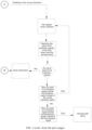
- the embodiments of the present disclosure first provide a control method, as shown in Fig. 1 and Fig. 2 .
- the control method may include the following steps.
- Step S 10 acquiring first transition signals in real time and recording the first time point of acquiring each of the first transition signals.
- Step S20 acquiring second transition signals in real time and recording the second time point of acquiring each of the second transition signals.
- Step S30 calculating the difference between the second time point and the corresponding first time point.
- Step S40 if the difference is positive, increasing or decreasing the count value by a set value, and if the difference is negative, decreasing or increasing the count value by a set value.
- Step S50 determining that the stepper motor is stalled when the count value does not increase or decrease within a set time period.
- the difference between the second time point and the corresponding first time point when the difference between the second time point and the corresponding first time point is positive, it indicates that the first time point of acquiring the first transition signal is less than the second time point of acquiring the second transition signal, and the first transition signal is ahead of the second transition signal.
- the difference between the second time point and the corresponding first time point when the difference between the second time point and the corresponding first time point is negative, it indicates that the first time point of acquiring the first transition signal is greater than the second time point of acquiring the second transition signal, and the second transition signal is ahead of the first transition signal. If the difference is positive, the count value is increased by the set value; and if the difference is negative, the count value is decreased by the set value.
- the stepper motor 1 is stalled.
- the first transition signal will always be ahead of the second transition signal, or the second transition signal will always be ahead of the first transition signal, so that the count value will always increase or decrease.
- the stepper motor 1 is stalled, it will not receive the first transition signal and the second transition signal, so that the count value will remain unchanged within the set time period.
- the stepper motor 1 When the stepper motor 1 is stalled and rebounds, initially, the first transition signal is ahead of the second transition signal, and then due to the rebound, the second transition signal is ahead of the first transition signal, causing the previously increasing count value to decrease; the original second transition signal is ahead of the first transition signal, and due to the rebound, the first transition signal is ahead of the second transition signal, causing the previously decreasing count value to increase.
- the control method and control device of the present disclosure make it more accurate, efficient, and convenient to determine the operating state of the stepper motor 1.
- control method and control device are applied to an electronic expansion valve. To more clearly explain the control method and control device, the following description is made for the electronic expansion valve.
- the electronic expansion valve may include a first sensor 2, a second sensor 3, a control device, a stepper motor 1, a valve, and so on.
- the control device controls the operation of the stepper motor 1, and the stepper motor 1 drives the valve to open and close.
- the stepper motor 1 may include a rotor 11 and a stator 12.
- the rotor 11 may include a permanent magnet, and the permanent magnet may include at least one pair of magnetic poles.
- the stator 12 may include a coil and a magnetic permeable part. A current that varies in a certain regular pattern flows through the coil, thereby forming an excitation magnetic field at the magnetic permeable part.
- the magnetic field of the permanent magnet of the rotor 11 interacts with the excitation magnetic field of the magnetic poles of the stator 12, allowing the rotor 11 to rotate around a central axis.
- the rotor 11 includes at least one pair of magnetic poles. Each pair of magnetic poles includes an N pole and an S pole, which are spaced apart along the circumferential direction of the rotor 11.
- the electronic expansion valve uses a stepper motor 1 with two phases and ten pairs of magnetic poles.
- the rotor 11 includes ten N poles and ten S poles, that is, the rotor 11 includes twenty magnetic poles and the twenty magnetic poles are arranged along the circumference of the rotor 11.
- the first sensor 2 and the second sensor 3 are located on the outer periphery of the rotor 11 and are arranged close to the rotor 11. When the rotor 11 rotates, the N poles and S poles of the rotor 11 alternately pass through the first sensor 2 and the second sensor 3.
- the first sensor 2 will sense the magnetic field changes of the rotor 11 and generate a periodic first feedback signal.
- the first feedback signal is square wave and includes a plurality of first transition signals.
- the second sensor 3 will sense the magnetic field changes of the rotor 11 and generate a periodic second feedback signal.
- the second feedback signal is square wave and includes a plurality of second transition signals.
- the first sensor 2 from the N pole to the S pole or from the S pole to the N pole, the first sensor 2 generates a first transition signal and the second sensor 3 generates a second transition signal.
- the first transition signal and the second transition signal transitions from low level to high level or from low level to high level.
- the stepper motor 1 runs one circle, that is, the rotor 11 rotates one revolution, it will generate 20 first transition signals and 20 second transition signals.
- the control device may be a microprocessor, a single-chip microcomputer, or the like, and is used to implement the control method described above.
- Step S10 acquiring first transition signals in real time and recording a first time point of acquiring each of the first transition signals.
- the first transition signal is a signal generated by the first sensor 2 sensing a change from the N pole to the S pole or from the S pole to the N pole, resulting in a transition from low level to high level or a transition from low level to high level.
- the rotor 11 rotating one revolution will generate 20 first transition signals, and the control device acquires 20 first transition signals in real time; and records the first time point of acquiring each of the first transition signals, that is, the control apparatus records 20 first time points, and the 20 first time points correspond one-to-one with the 20 first transition signals.
- Step S20 acquiring second transition signals in real time and recording a second time point of acquiring each of the second transition signals.
- the second transition signal is a signal generated by the second sensor 3 sensing a change from the N pole to the S pole or from the S pole to the N pole, resulting in a transition from low level to high level or a transition from low level to high level.
- the rotor 11 rotating one revolution will generate 20 second transition signals, and the control device acquires 20 second transition signals in real time; and the control device records a second time point of acquiring each of the second transition signals, that is, the control device records 20 second time points, and the 20 second time points correspond one-to-one with the 20 second transition signals.
- the number of the first transition signals and the second transition signals is related to the number of pairs of magnetic poles included in the rotor 11.
- the number of pairs of magnetic poles changes, and the number of the first transition signals and the second transition signals also changes, but both fall within the scope of protection of the present disclosure.
- Step S30 calculating the difference between the second time point and the corresponding first time point.
- the number of second time points is the same as the number of first time points.
- the 20 first time points are sorted in order of recording as T101, T102, T103, ..., T119, T120.
- the 20 second time points are sorted in order of recording as T201, T202, T203, ..., T219, T220.
- the first time points corresponding to the second time points refer to their sequence numbers being consistent.
- the first time point corresponding to the second time point T101 is T201
- the first time point corresponding to the second time point T102 is T202, and so on. Calculate the difference between the second time point and the corresponding first time point, that is, subtract the first time point from the second time point, for example, T201-T101.
- Step S40 if the difference is positive, increasing or decreasing the count value by a set value, and if the difference is negative, decreasing or increasing the count value by a set value.
- the difference between the second time point and the corresponding first time point is positive, indicating that the first time point of acquiring the first transition signal is less than the second time point of acquiring the second transition signal, and the first transition signal is ahead of the second transition signal, that is, the first sensor 2 senses the change from the N pole to the S pole or the operation from the S pole to the N pole first, and it can be determined that the stepper motor 1 rotates in a forward direction.
- the set value can be 1, that is, if the difference is positive, the count value is increased by 1.
- the difference between the second time point and the corresponding first time point is negative, it indicates that the first time point of acquiring the first transition signal is greater than the second time point of acquiring the second transition signal, and the second transition signal is ahead of the first transition signal, that is, the second sensor 3 senses the change from the N pole to the S pole or the operation from the S pole to the N pole first, and it can be determined that the stepper motor 1 rotates in a reverse direction.
- the set value can be 1, that is, if the difference is negative, the count value is decreased by 1.
- the above set value is only an example, and the value can be set according to needs.
- the value of the above set value does not constitute a limitation of the present disclosure.
- different counting methods can also be adopted. For example, if the difference value is positive, the count value is decreased by the set value, and if the difference value is negative, the count value is increased by the set value.
- Step S50 when the count value does not increase or decrease within the set time period, determining that the stepper motor 1 is stalled.
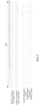
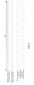
- the stepper motor 1 when the stepper motor 1 is operating normally, for example, when it is rotating in the forward direction, referring to Fig. 3 , the first transition signal will always be ahead of the second transition signal, causing the count value to always gradually increase; for example, when it is rotating in the reverse direction, referring to Fig. 4 , the second transition signal will always be ahead of the first transition signal, causing the count value to always gradually decrease.
- Stall can include a first stall and a second stall.
- the first stall can be a stall rebound, which typically occurs near the top dead center and bottom dead center.
- the second stall can be a stall stuck, which typically occurs between the top dead center and bottom dead center.
- the stepper motor 1 when the stepper motor 1 is stalled and rebounds (i.e., the first stall), initially, the first transition signals are ahead of the second transition signals, and then due to the rebound, the second transition signals are ahead of the first transition signal, causing the previously increasing count value to decrease. Therefore, when the count value does not increase but decreases within the set time period, it is determined that the stepper motor 1 has a first stall. Similarly, initially, the second transition signals are ahead of the first transition signals, and then due to the rebound, the first transition signals are ahead of the second transition signals, causing the previously decreasing count value to increase. Therefore, when the count value does not decrease but increases within the set time period, it is determined that the stepper motor 1 has a first stall.
- the stepper motor 1 of the electronic expansion valve uses a thirty-two micro-step control scheme.
- One full step includes thirty-two micro-steps.
- the stepper motor 1 runs two full steps, corresponding to a change in the magnetic pole of the rotor 11. That is, the running duration after a transition signal transitions includes time corresponding to two full steps, which is time of theoretically sixty-four micro-steps.
- the stepper motor 1 runs for corresponding time of two full steps.
- the first sensor 2 corresponds to the magnetic pole of the rotor 11 rotating from one end of the N pole to the junction of the N and S poles, and the corresponding first transition signal is at high level.
- the first sensor 2 corresponds to the magnetic pole of the rotor 11 changing from the N pole to the S pole, and the first transition signal transitions to low level.
- the stepper motor 1 runs for two full steps, the first sensor 2 corresponds to the magnetic pole of the rotor 11 rotating from the S pole to the junction of the N and S poles, and the first transition signal remains at low level.
- the first sensor 2 corresponds to the magnetic pole of the rotor 11 changing from the S pole to the N pole, and the first transition signal transitions to high level.
- the rotor 11 rotates one revolution, the stepper motor 1 runs for 40 full steps, and produces 20 first transition signals.
- the running duration of the high and low levels of the first transition signals is equal to the corresponding time of two full steps.
- a set time period is defined as the time corresponding to at least two full steps of the stepper motor 1.
- steps S10 and S20 may be interchanged, and steps S30 and S40 may be combined into one step.
- the embodiments of the present disclosure also provide a control device.
- the control device may include a first acquiring component 121, a second acquiring component 122, a calculating component 123, a counting component 124, and a judging component 125.
- the first acquiring component 121 may be configured to acquire first transition signals in real time and record a first time point of acquiring each of the first transition signals.
- the second acquiring component 122 may be configured to acquire second transition signals in real time and record a second time point of acquiring each of the second transition signals.
- the calculating component 123 may be configured to calculate the difference between the second time point and the corresponding first time point.
- the counting component 124 may be configured to increase or decrease a set value if the difference is positive, and correspondingly decrease or increase the set value if the difference is negative.
- the determining component 125 may be configured to determine that the stepper motor 1 is stalled if the count value does not increase or decrease within the set time period.
- determining that the stepper motor 1 is stalled when the count value does not increase or decrease within a set time period includes: determining that the stepper motor 1 has a first stall when the count value does not increase but decreases within the set time period; or determining that the stepper motor 1 has a first stall when the count value does not decrease but increases.
- determining that the stepper motor 1 is stalled when the count value does not increase or decrease within a set time period includes determining that the stepper motor 1 has a second stall when the count value remains unchanged within a set time period.
- stepper motor 1 rotates in the forward direction; if the difference is negative, it is determined that the stepper motor 1 rotates in the reverse direction.
- the embodiments of the present disclosure also provide an electronic expansion valve, referring to the structural schematic diagram of the electronic expansion valve shown in Fig. 8 , Fig. 9 and Fig. 10 .
- the electronic expansion valve may include a stepper motor 1, a first sensor 2, a second sensor 3, and a control device.
- the stepper motor 1 may include a rotor 11 and a stator 12, and the rotor 11 includes a permanent magnet.
- the first sensor 2 is disposed on the periphery of the permanent magnet, and the first sensor 2 senses the magnetic field change of the rotor 11 and outputs first transition signals.
- the second sensor 3 is disposed on the periphery of the permanent magnet, and the second sensor 3 senses the magnetic field change of the rotor 11 and outputs second transition signals.
- the first sensor 2 and the second sensor 3 are arranged alternately.
- the control device is electrically connected to the first sensor 2 and the second sensor 3, and the control device is the control device described in any of the above items.
- stepper motor 1 The specific structure of the stepper motor 1 has also been described in detail above, so it will not be repeated here.
- the first sensor 2 can be a Hall sensor or a position sensor, and the first transition signal is a Hall signal.
- the second sensor 3 can also be a Hall sensor or a position sensor, and the second transition signal is also a Hall signal.
- the first sensor 2 and the second sensor 3 are arranged alternately, so that the first sensor 2 and the second sensor 3 cannot simultaneously sense the magnetic field change of the rotor 11.
- m is a positive integer, m is less than or equal to 2n; n is the number of pairs of the magnetic poles, and ⁇ is a positive number less than 360 ° 2 n .
- the angle between the center line of the first sensor 2 and the center line of the second sensor 3 is ⁇ , which is approximately 154 degrees.
- the first sensor 2 may include a main body 21 and a connecting portion 22.
- the connecting portion 22 is electrically connected to the circuit board 4 and is welded and fixed to the circuit board 4.
- a communication hole 41 is formed on the circuit board 4, and the connecting portion 22 is disposed through the communication hole 41 and is welded and fixed to the circuit board 4.
- the electronic expansion valve may also include a valve, and the valve may include a valve needle 5, a valve seat 6, a valve body 7, and a valve port component 8.
- the valve needle 5 is driven by a rotor 11 to move between a top dead center and a bottom dead center.
- the valve needle 5 is located at the bottom dead center, the flow channels on both sides of the valve port are blocked and the valve port is closed.
- the valve needle 5 moves from the bottom dead center to the top dead center, the valve port is gradually opened, and the flow channels on both sides are connected through the gap between the valve port and the valve needle 5.
- the opening of the valve port reaches its maximum.
- the flow channels on both sides of the valve port are formed on the valve body 7.
- the valve port is located between the flow channels of two sides.
- the valve port component 8 is formed with a valve port.
- the valve port component 8 is fixedly connected to the valve body 7.
- the valve seat 6 is fixedly connected to the valve body 7.
- the valve needle 5 and the rotor 11 are connected and arranged.
- the electronic expansion valve may also include a screw rod 9, a nut component 10, and a stop rod.
- the nut component 10 is sleeved on the periphery of the screw rod, and the nut component 10 and the screw rod are threaded engaged.
- the nut component 10 is fixedly disposed relative to the valve seat 6, and the nut component 10 is fixedly disposed within the inner ring of the rotor 11.
- the rotor 11 can drive the nut component 10 to rotate, allowing the screw rod to move upward or downward relative to the nut component 10.
- the stop rod is fixedly connected to the screw rod through a connecting plate, and the stop rod moves upward or downward relative to the nut component 10.
- the stop rod and the nut component 10 cooperate to limit the motion of the screw rod between the top dead center and the bottom dead center. Since the valve needle 5 is fixedly connected to the screw rod, the motion of the valve needle 5 is limited to the distance between the top dead center and the bottom dead center.
- An elastic element 11 is disposed between the valve needle 5 and the screw rod 9, and the elastic element 11 may be a spring. When the valve needle 5 moves to the bottom dead center, the valve needle 5 and the valve port component 8 come into elastic contact, buffering the valve needle 5 and the valve port component 8, which is beneficial to improving the life of the two components.
Landscapes
- Engineering & Computer Science (AREA)
- General Engineering & Computer Science (AREA)
- Mechanical Engineering (AREA)
- Physics & Mathematics (AREA)
- Thermal Sciences (AREA)
- General Physics & Mathematics (AREA)
- Automation & Control Theory (AREA)
- Power Engineering (AREA)
- Control Of Stepping Motors (AREA)
- Electrically Driven Valve-Operating Means (AREA)
Abstract
Description
- The present disclosure claims the priority of the
Chinese patent application with the application number 202110564209.0 and the title of "control method, control apparatus, and electronic expansion valve" filed on May 24, 2021 - The present disclosure relates to the technical field of automobiles, and specifically to a control method and a control apparatus, including an electronic expansion valve of the control apparatus.
- In the vehicle system, the electronic expansion valve is used in the refrigeration system to regulate the refrigerant flow. The electronic expansion valve includes a stepper motor, and the stepper motor is controlled by a control device to rotate. When the stepper motor encounters an obstacle during rotation, it may stall. Due to the open-loop control for the electronic expansion valve, it is impossible to accurately know the current state and position of the valve body in the case of valve stall and out-of-step. Especially during the reset process, due to the fully closed state of the valve core, long-term continuous reset of stalling can easily lead to changes in the characteristics of the spring, resulting in long reset time and high noise level. If the valve core is stuck, due to the flexible deformation of the spring, the transformation of the counter electromotive force slows down, and it is difficult for the control device to accurately determine stalling through speed loss.
- It should be noted that the information disclosed in the background section is only used to enhance the understanding of the background of the present disclosure, and therefore it may include information that does not constitute prior art known to those skilled in the art.
- The purpose of the present disclosure is to overcome the shortcomings of the prior art and provide a control method, a control device, and an electronic expansion valve.
- According to one aspect of the present disclosure, there is provided a control method, including: acquiring first transition signals in real time and recording a first time point of acquiring each of the first transition signals; acquiring second transition signals in real time and recording a second time point of acquiring each of the second transition signals; calculating a difference between the second time point and a corresponding first time point; if the difference is positive, increasing or decreasing a count value by a set value, and if the difference is negative, decreasing or increasing the count value by the set value; determining that a stepper motor is stalled when the count value does not increase or decrease within a set time period.
- In an example embodiment of the present disclosure, determining that the stepper motor is stalled when the count value does not increase or decrease within the set time period includes: determining that the stepper motor has a first stall when the count value does not increase but decreases within the set time period; or determining that the stepper motor has a first stall when the count value does not decrease but increases within the set time period.
- In an example embodiment of the present disclosure, determining that the stepper motor is stalled when the count value does not increase or decrease within the set time period includes: determining that the stepper motor has a second stall when the count value remains unchanged within the set time period.
- In an example embodiment of the present disclosure, if the difference is positive, the stepper motor is determined to rotate in a forward direction; and if the difference is negative, the stepper motor is determined to rotate in a reverse direction.
- According to another aspect of the present disclosure, there is provided a control device, including: a first acquiring component configured to acquire first transition signals in real time and record a first time point of acquiring each of the first transition signals; a second acquiring component configured to acquire second transition signals in real time and record a second time point of acquiring each of the second transition signals; a calculating component configured to calculate a difference between the second time point and a corresponding first time point; a counting component configured to increase or decrease a count value by a set value if the difference is positive, and correspondingly decrease or increase the count value by the set value if the difference is negative; a determining component configured to determine that a stepper motor is stalled when the count value does not increase or decrease within a set time period.
- In an example embodiment of the present disclosure, determining that the stepper motor is stalled when the count value does not increase or decrease within the set time period includes: determining that the stepper motor has a first stall when the count value does not increase but decreases within the set time period; or determining that the stepper motor has a first stall when the count value does not decrease but increases within the set time period.
- In an example embodiment of the present disclosure, determining that the stepper motor is stalled when the count value does not increase or decrease within the set time period includes: determining that the stepper motor has a second stall when the count value remains unchanged within the set time period.
- According to yet another aspect of the present disclosure, there is provided an electronic expansion valve, including: a stepper motor including a rotor and a stator, where the rotor includes a permanent magnet; a first sensor disposed on the periphery of the permanent magnet, where the first sensor senses a magnetic field change of the rotor and outputs a first transition signal; a second sensor disposed on the periphery of the permanent magnet, wherein the second sensor senses the magnetic field change of the rotor and outputs a second transition signal, and the first sensor and the second sensor are disposed alternately; a control device electrically connected to the first sensor and the second sensor, where the control device is the control device according to any one of
claims 5 to 7. - In an example embodiment of the present disclosure, an angle between the first sensor and the second sensor is α,


- In an example embodiment of the present disclosure, the rotor includes at least one pair of magnetic poles, each pair of magnetic poles includes an N pole and an S pole, and one of the first transition signals is generated when the first sensor senses the magnetic pole of the rotor changes from the N pole to the S pole or from the S pole to the N pole; and one of the second transition signals is generated when the second sensor senses the magnetic pole of the rotor changes from the N pole to the S pole or from the S pole to the N pole.
- It should be understood that, the general description above and the detailed description in the following text are only illustrative and explanatory, and cannot limit this disclosure.
- The drawings herein are incorporated into the specification and constitute a part of the specification, showing embodiments consistent with the present disclosure and serving, together with the specification, to explain the principles of the present disclosure. It is apparent that the drawings described below are merely some embodiments of the present disclosure, and those skilled in the art can obtain other drawings based on these drawings without creative labor.
-
Fig. 1 is a flow diagram of an example embodiment of the control method of the present disclosure. -
Fig. 2 is a schematic diagram of a control flow of an example embodiment of the control method of the present disclosure. -
Fig. 3 is a schematic diagram of the corresponding relationship of the number of running steps, the rotor magnetic pole, the first feedback signal and the second feedback signal in time when the stepper motor of the electronic expansion valve rotates in a forward direction. -
Fig. 4 is a schematic diagram of the corresponding relationship of the number of running steps, the rotor magnetic pole, the first feedback signal and the second feedback signal in time when the stepper motor of the electronic expansion valve rotates in a reverse direction. -
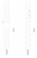
Fig. 5 is a schematic diagram of the principle when the electronic expansion valve is stalled and stuck. -
Fig. 6 is a schematic diagram of the principle when the electronic expansion valve is stalled and rebounds. -
Fig. 7 is a schematic block diagram of an example embodiment of the control device of the present disclosure. -
Fig. 8 is a structural schematic diagram of an exemplary embodiment of an electronic expansion valve of the present disclosure. -
Fig. 9 is a schematic cross-sectional view taken along the line A-A inFig. 8 . -
Fig. 10 is a partial enlarged schematic diagram of the part indicated by I inFig. 9 . -
- 1. Stepper motor; 11. Rotor; 12. Stator;
- 2. First sensor; 21. Main body; 22. Connecting part;
- 3. Second sensor;
- 4. Circuit board; 41. Connecting hole;
- 5. Valve needle; 6. Valve seat; 7. Valve body; 8. Valve port components; 9. Screw rod; 10. Nut components; 11. Elastic element;
- 121. First acquiring component; 122. Second acquiring component; 123. Calculating component; 124. Counting component; 125. Determining component.
- Example embodiments will now be described more fully with reference to the accompanying drawings. However, example embodiments can be implemented in various forms and should not be construed as limited to the embodiments set forth herein. Rather, these embodiments are provided so that this disclosure will be thorough and complete, and will fully convey the concept of example embodiments to those skilled in the art. The same reference numbers represent the same or similar structures throughout the figures, and thus detailed descriptions thereof will be omitted. In addition, the figures are schematic illustrations of the present disclosure only and are not necessarily drawn to scale.
- Although relative terms such as "up" and "down" are used to describe the relative relationship of one component of an icon with respect to another component in the specification, these terms are used in this specification for convenience only, such as in accordance with the direction of the examples described in the figures. It is understood that if the icon device is flipped upside down, the component described as "up" will become the component described as "down". When a structure is "on top" of another structure, it may refer to the fact that one structure is formed integrally on top of another structure, or it may refer to the fact that one structure is "directly" disposed on top of another structure, or it may refer to the fact that one structure is "indirectly" disposed on top of another structure through other structure.
- The terms "one", "a", "the", "said", and "at least one" are used to indicate the existence of one or more elements/components/etc.; the terms "including" and "having" are used to indicate an open-ended inclusion and refer to the existence of additional elements/components/etc. in addition to the listed elements/components/etc.; the terms "first", "second", and "third" are used only as markers and do not limit the number of their objects.
- The embodiments of the present disclosure first provide a control method, as shown in
Fig. 1 andFig. 2 . The control method may include the following steps. - Step S 10: acquiring first transition signals in real time and recording the first time point of acquiring each of the first transition signals.
- Step S20: acquiring second transition signals in real time and recording the second time point of acquiring each of the second transition signals.
- Step S30: calculating the difference between the second time point and the corresponding first time point.
- Step S40, if the difference is positive, increasing or decreasing the count value by a set value, and if the difference is negative, decreasing or increasing the count value by a set value.
- Step S50: determining that the stepper motor is stalled when the count value does not increase or decrease within a set time period.
- According to the control method and control device of the present disclosure, when the difference between the second time point and the corresponding first time point is positive, it indicates that the first time point of acquiring the first transition signal is less than the second time point of acquiring the second transition signal, and the first transition signal is ahead of the second transition signal. On the contrary, when the difference between the second time point and the corresponding first time point is negative, it indicates that the first time point of acquiring the first transition signal is greater than the second time point of acquiring the second transition signal, and the second transition signal is ahead of the first transition signal. If the difference is positive, the count value is increased by the set value; and if the difference is negative, the count value is decreased by the set value. Within the set time period, and when the count value is not increased or decreased, it is determined that the stepper motor 1 is stalled. When the stepper motor 1 is operating normally, the first transition signal will always be ahead of the second transition signal, or the second transition signal will always be ahead of the first transition signal, so that the count value will always increase or decrease. When the stepper motor 1 is stalled, it will not receive the first transition signal and the second transition signal, so that the count value will remain unchanged within the set time period. When the stepper motor 1 is stalled and rebounds, initially, the first transition signal is ahead of the second transition signal, and then due to the rebound, the second transition signal is ahead of the first transition signal, causing the previously increasing count value to decrease; the original second transition signal is ahead of the first transition signal, and due to the rebound, the first transition signal is ahead of the second transition signal, causing the previously decreasing count value to increase. The control method and control device of the present disclosure make it more accurate, efficient, and convenient to determine the operating state of the stepper motor 1.
- The control method and control device are applied to an electronic expansion valve. To more clearly explain the control method and control device, the following description is made for the electronic expansion valve.
- In this example embodiment, as shown in
Fig. 8 ,Fig. 9, and Fig. 10 , the electronic expansion valve may include afirst sensor 2, asecond sensor 3, a control device, a stepper motor 1, a valve, and so on. The control device controls the operation of the stepper motor 1, and the stepper motor 1 drives the valve to open and close. - The stepper motor 1 may include a
rotor 11 and astator 12. Therotor 11 may include a permanent magnet, and the permanent magnet may include at least one pair of magnetic poles. Thestator 12 may include a coil and a magnetic permeable part. A current that varies in a certain regular pattern flows through the coil, thereby forming an excitation magnetic field at the magnetic permeable part. The magnetic field of the permanent magnet of therotor 11 interacts with the excitation magnetic field of the magnetic poles of thestator 12, allowing therotor 11 to rotate around a central axis. - The
rotor 11 includes at least one pair of magnetic poles. Each pair of magnetic poles includes an N pole and an S pole, which are spaced apart along the circumferential direction of therotor 11. In this embodiment, the electronic expansion valve uses a stepper motor 1 with two phases and ten pairs of magnetic poles. Therotor 11 includes ten N poles and ten S poles, that is, therotor 11 includes twenty magnetic poles and the twenty magnetic poles are arranged along the circumference of therotor 11. - The
first sensor 2 and thesecond sensor 3 are located on the outer periphery of therotor 11 and are arranged close to therotor 11. When therotor 11 rotates, the N poles and S poles of therotor 11 alternately pass through thefirst sensor 2 and thesecond sensor 3. Thefirst sensor 2 will sense the magnetic field changes of therotor 11 and generate a periodic first feedback signal. The first feedback signal is square wave and includes a plurality of first transition signals. Thesecond sensor 3 will sense the magnetic field changes of therotor 11 and generate a periodic second feedback signal. The second feedback signal is square wave and includes a plurality of second transition signals. That is, from the N pole to the S pole or from the S pole to the N pole, thefirst sensor 2 generates a first transition signal and thesecond sensor 3 generates a second transition signal. The first transition signal and the second transition signal transitions from low level to high level or from low level to high level. When the stepper motor 1 runs one circle, that is, therotor 11 rotates one revolution, it will generate 20 first transition signals and 20 second transition signals. - The control device may be a microprocessor, a single-chip microcomputer, or the like, and is used to implement the control method described above.
- The steps of the control method will be described in detail hereinafter.
- Step S10: acquiring first transition signals in real time and recording a first time point of acquiring each of the first transition signals.
- In this example embodiment, the first transition signal is a signal generated by the
first sensor 2 sensing a change from the N pole to the S pole or from the S pole to the N pole, resulting in a transition from low level to high level or a transition from low level to high level. Therotor 11 rotating one revolution will generate 20 first transition signals, and the control device acquires 20 first transition signals in real time; and records the first time point of acquiring each of the first transition signals, that is, the control apparatus records 20 first time points, and the 20 first time points correspond one-to-one with the 20 first transition signals. - Step S20: acquiring second transition signals in real time and recording a second time point of acquiring each of the second transition signals.
- In this example embodiment, the second transition signal is a signal generated by the
second sensor 3 sensing a change from the N pole to the S pole or from the S pole to the N pole, resulting in a transition from low level to high level or a transition from low level to high level. Therotor 11 rotating one revolution will generate 20 second transition signals, and the control device acquires 20 second transition signals in real time; and the control device records a second time point of acquiring each of the second transition signals, that is, thecontrol device records 20 second time points, and the 20 second time points correspond one-to-one with the 20 second transition signals. - It should be noted that the number of the first transition signals and the second transition signals is related to the number of pairs of magnetic poles included in the
rotor 11. In other example embodiments of the present disclosure, the number of pairs of magnetic poles changes, and the number of the first transition signals and the second transition signals also changes, but both fall within the scope of protection of the present disclosure. - Step S30: calculating the difference between the second time point and the corresponding first time point.
- In this example embodiment, the number of second time points is the same as the number of first time points. The 20 first time points are sorted in order of recording as T101, T102, T103, ..., T119, T120. The 20 second time points are sorted in order of recording as T201, T202, T203, ..., T219, T220. The first time points corresponding to the second time points refer to their sequence numbers being consistent. For example, the first time point corresponding to the second time point T101 is T201, the first time point corresponding to the second time point T102 is T202, and so on. Calculate the difference between the second time point and the corresponding first time point, that is, subtract the first time point from the second time point, for example, T201-T101.
- Step S40, if the difference is positive, increasing or decreasing the count value by a set value, and if the difference is negative, decreasing or increasing the count value by a set value.
- In this example embodiment, the difference between the second time point and the corresponding first time point is positive, indicating that the first time point of acquiring the first transition signal is less than the second time point of acquiring the second transition signal, and the first transition signal is ahead of the second transition signal, that is, the
first sensor 2 senses the change from the N pole to the S pole or the operation from the S pole to the N pole first, and it can be determined that the stepper motor 1 rotates in a forward direction. The set value can be 1, that is, if the difference is positive, the count value is increased by 1. - On the contrary, if the difference between the second time point and the corresponding first time point is negative, it indicates that the first time point of acquiring the first transition signal is greater than the second time point of acquiring the second transition signal, and the second transition signal is ahead of the first transition signal, that is, the
second sensor 3 senses the change from the N pole to the S pole or the operation from the S pole to the N pole first, and it can be determined that the stepper motor 1 rotates in a reverse direction. The set value can be 1, that is, if the difference is negative, the count value is decreased by 1. - Of course, the above set value is only an example, and the value can be set according to needs. The value of the above set value does not constitute a limitation of the present disclosure.
- It should be noted that in other example embodiments of the present disclosure, different counting methods can also be adopted. For example, if the difference value is positive, the count value is decreased by the set value, and if the difference value is negative, the count value is increased by the set value.
- Step S50: when the count value does not increase or decrease within the set time period, determining that the stepper motor 1 is stalled.
- In this example embodiment, when the stepper motor 1 is operating normally, for example, when it is rotating in the forward direction, referring to
Fig. 3 , the first transition signal will always be ahead of the second transition signal, causing the count value to always gradually increase; for example, when it is rotating in the reverse direction, referring toFig. 4 , the second transition signal will always be ahead of the first transition signal, causing the count value to always gradually decrease. - Stall can include a first stall and a second stall. The first stall can be a stall rebound, which typically occurs near the top dead center and bottom dead center. The second stall can be a stall stuck, which typically occurs between the top dead center and bottom dead center.
- Referring to
Fig. 5 , as indicated by M, when the stepper motor 1 is stalled and stuck (i.e., the second stall), therotor 11 does not rotate, and therefore therotor 11 does not receive the first transition signals and the second transition signals, resulting in the count value remaining unchanged for the set time period. - Referring to
Fig. 6 , as indicated by N, when the stepper motor 1 is stalled and rebounds (i.e., the first stall), initially, the first transition signals are ahead of the second transition signals, and then due to the rebound, the second transition signals are ahead of the first transition signal, causing the previously increasing count value to decrease. Therefore, when the count value does not increase but decreases within the set time period, it is determined that the stepper motor 1 has a first stall. Similarly, initially, the second transition signals are ahead of the first transition signals, and then due to the rebound, the first transition signals are ahead of the second transition signals, causing the previously decreasing count value to increase. Therefore, when the count value does not decrease but increases within the set time period, it is determined that the stepper motor 1 has a first stall. - In this example embodiment, the stepper motor 1 of the electronic expansion valve uses a thirty-two micro-step control scheme. One full step includes thirty-two micro-steps. The stepper motor 1 runs two full steps, corresponding to a change in the magnetic pole of the
rotor 11. That is, the running duration after a transition signal transitions includes time corresponding to two full steps, which is time of theoretically sixty-four micro-steps. - Specifically, referring to
Fig. 3 , when the electronic expansion valve is operating normally, the stepper motor 1 runs for corresponding time of two full steps. Thefirst sensor 2 corresponds to the magnetic pole of therotor 11 rotating from one end of the N pole to the junction of the N and S poles, and the corresponding first transition signal is at high level. As the stepper motor 1 runs, thefirst sensor 2 corresponds to the magnetic pole of therotor 11 changing from the N pole to the S pole, and the first transition signal transitions to low level. The stepper motor 1 runs for two full steps, thefirst sensor 2 corresponds to the magnetic pole of therotor 11 rotating from the S pole to the junction of the N and S poles, and the first transition signal remains at low level. As the stepper motor 1 runs, thefirst sensor 2 corresponds to the magnetic pole of therotor 11 changing from the S pole to the N pole, and the first transition signal transitions to high level. Repeatedly running in this way, therotor 11 rotates one revolution, the stepper motor 1 runs for 40 full steps, and produces 20 first transition signals. The running duration of the high and low levels of the first transition signals is equal to the corresponding time of two full steps. - In this example embodiment, a set time period is defined as the time corresponding to at least two full steps of the stepper motor 1. The set time period T is related to the motor speed n, the number of pairs p of magnetic poles of the
rotor 11, and the number of motor phases m, with the specific relationship being as follows: T=60/(n*m*P), where n is in revolutions per minute, m=2, and p=10. - It should be noted that although the steps of the control method in this disclosure are described in a specific order in the drawings, this does not require or imply that the steps must be performed in that specific order, or that all of the steps shown must be performed to achieve the desired result. Additional or alternative steps may be omitted, a plurality of steps may be combined into one step, and/or one step may be decomposed into a plurality of steps. For example, steps S10 and S20 may be interchanged, and steps S30 and S40 may be combined into one step.
- Furthermore, the embodiments of the present disclosure also provide a control device. Referring to
Fig. 7 , the control device may include a first acquiringcomponent 121, a second acquiringcomponent 122, a calculatingcomponent 123, acounting component 124, and a judgingcomponent 125. The first acquiringcomponent 121 may be configured to acquire first transition signals in real time and record a first time point of acquiring each of the first transition signals. The second acquiringcomponent 122 may be configured to acquire second transition signals in real time and record a second time point of acquiring each of the second transition signals. The calculatingcomponent 123 may be configured to calculate the difference between the second time point and the corresponding first time point. Thecounting component 124 may be configured to increase or decrease a set value if the difference is positive, and correspondingly decrease or increase the set value if the difference is negative. The determiningcomponent 125 may be configured to determine that the stepper motor 1 is stalled if the count value does not increase or decrease within the set time period. - In this example embodiment, determining that the stepper motor 1 is stalled when the count value does not increase or decrease within a set time period includes: determining that the stepper motor 1 has a first stall when the count value does not increase but decreases within the set time period; or determining that the stepper motor 1 has a first stall when the count value does not decrease but increases.
- In this example embodiment, determining that the stepper motor 1 is stalled when the count value does not increase or decrease within a set time period includes determining that the stepper motor 1 has a second stall when the count value remains unchanged within a set time period.
- In this example embodiment, if the difference is positive, it is determined that the stepper motor 1 rotates in the forward direction; if the difference is negative, it is determined that the stepper motor 1 rotates in the reverse direction.
- The specific details of each component in the above control device have been described in detail in the corresponding control method, so they are not repeated here.
- Furthermore, the embodiments of the present disclosure also provide an electronic expansion valve, referring to the structural schematic diagram of the electronic expansion valve shown in
Fig. 8 ,Fig. 9 and Fig. 10 . The electronic expansion valve may include a stepper motor 1, afirst sensor 2, asecond sensor 3, and a control device. The stepper motor 1 may include arotor 11 and astator 12, and therotor 11 includes a permanent magnet. Thefirst sensor 2 is disposed on the periphery of the permanent magnet, and thefirst sensor 2 senses the magnetic field change of therotor 11 and outputs first transition signals. Thesecond sensor 3 is disposed on the periphery of the permanent magnet, and thesecond sensor 3 senses the magnetic field change of therotor 11 and outputs second transition signals. Thefirst sensor 2 and thesecond sensor 3 are arranged alternately. The control device is electrically connected to thefirst sensor 2 and thesecond sensor 3, and the control device is the control device described in any of the above items. - The specific structure of the control device and control method have been described in detail above, so they will not be repeated here.
- The specific structure of the stepper motor 1 has also been described in detail above, so it will not be repeated here.
- The
first sensor 2 can be a Hall sensor or a position sensor, and the first transition signal is a Hall signal. Thesecond sensor 3 can also be a Hall sensor or a position sensor, and the second transition signal is also a Hall signal. Thefirst sensor 2 and thesecond sensor 3 are arranged alternately, so that thefirst sensor 2 and thesecond sensor 3 cannot simultaneously sense the magnetic field change of therotor 11. Specifically, the angle between thefirst sensor 2 and thesecond sensor 3 is α, that is, the angle between the center line of thefirst sensor 2 and the center line of thesecond sensor 3 is α,
- In the formula, m is a positive integer, m is less than or equal to 2n; n is the number of pairs of the magnetic poles, and β is a positive number less than

- In the present exemplary embodiment, the angle between the center line of the
first sensor 2 and the center line of thesecond sensor 3 is α, which is approximately 154 degrees. - The
first sensor 2 may include amain body 21 and a connectingportion 22. The connectingportion 22 is electrically connected to thecircuit board 4 and is welded and fixed to thecircuit board 4. Specifically, acommunication hole 41 is formed on thecircuit board 4, and the connectingportion 22 is disposed through thecommunication hole 41 and is welded and fixed to thecircuit board 4. - The electronic expansion valve may also include a valve, and the valve may include a
valve needle 5, avalve seat 6, avalve body 7, and avalve port component 8. Thevalve needle 5 is driven by arotor 11 to move between a top dead center and a bottom dead center. When thevalve needle 5 is located at the bottom dead center, the flow channels on both sides of the valve port are blocked and the valve port is closed. As thevalve needle 5 moves from the bottom dead center to the top dead center, the valve port is gradually opened, and the flow channels on both sides are connected through the gap between the valve port and thevalve needle 5. When thevalve needle 5 reaches the top dead center, the opening of the valve port reaches its maximum. In this embodiment, the flow channels on both sides of the valve port are formed on thevalve body 7. The valve port is located between the flow channels of two sides. Thevalve port component 8 is formed with a valve port. Thevalve port component 8 is fixedly connected to thevalve body 7. Thevalve seat 6 is fixedly connected to thevalve body 7. Thevalve needle 5 and therotor 11 are connected and arranged. - The electronic expansion valve may also include a
screw rod 9, anut component 10, and a stop rod. Thenut component 10 is sleeved on the periphery of the screw rod, and thenut component 10 and the screw rod are threaded engaged. Thenut component 10 is fixedly disposed relative to thevalve seat 6, and thenut component 10 is fixedly disposed within the inner ring of therotor 11. Therotor 11 can drive thenut component 10 to rotate, allowing the screw rod to move upward or downward relative to thenut component 10. The stop rod is fixedly connected to the screw rod through a connecting plate, and the stop rod moves upward or downward relative to thenut component 10. The stop rod and thenut component 10 cooperate to limit the motion of the screw rod between the top dead center and the bottom dead center. Since thevalve needle 5 is fixedly connected to the screw rod, the motion of thevalve needle 5 is limited to the distance between the top dead center and the bottom dead center. Anelastic element 11 is disposed between thevalve needle 5 and thescrew rod 9, and theelastic element 11 may be a spring. When thevalve needle 5 moves to the bottom dead center, thevalve needle 5 and thevalve port component 8 come into elastic contact, buffering thevalve needle 5 and thevalve port component 8, which is beneficial to improving the life of the two components. However, when a stall occurs near the top dead center and the bottom dead center, due to the flexible deformation of theelastic element 11, a rebound may occur, resulting in a periodic oscillatory waveform of the pulses fed back by the first sensor and the second sensor, making it impossible to determine whether a stall has occurred or making it possible to misjudge a stall. - Those skilled in the art will easily conceive of other embodiments of the present disclosure after considering the specification and practicing the disclosure herein. The present application aims to cover any variations, uses, or adaptations of the present disclosure, which comply with the general principles of the present disclosure and include common knowledge or conventional technical means in the technical field which is not disclosed in the present disclosure. The specification and embodiments are only regarded as exemplary, and the true scope and spirit of the present disclosure are indicated by the appended claims.
Claims (10)
- A control method, comprising:acquiring first transition signals in real time and recording a first time point of acquiring each of the first transition signals;acquiring second transition signals in real time and recording a second time point of acquiring each of the second transition signals;calculating a difference between the second time point and a corresponding first time point;if the difference is positive, increasing or decreasing a count value by a set value, and if the difference is negative, decreasing or increasing the count value by the set value;determining that a stepper motor is stalled when the count value does not increase or decrease within a set time period.
- The control method according to claim 1, wherein determining that the stepper motor is stalled when the count value does not increase or decrease within the set time period comprises:determining that the stepper motor has a first stall when the count value does not increase but decreases within the set time period; ordetermining that the stepper motor has a first stall when the count value does not decrease but increases within the set time period.
- The control method according to claim 1, wherein determining that the stepper motor is stalled when the count value does not increase or decrease within the set time period comprises:
determining that the stepper motor has a second stall when the count value remains unchanged within the set time period. - The control method according to claim 1, wherein the stepper motor is determined to rotate in a forward direction in response to the difference being positive; and the stepper motor is determined to rotate in a reverse direction in response to the difference being negative.
- A control device, comprising:a first acquiring component configured to acquire first transition signals in real time and record a first time point of acquiring each of the first transition signals;a second acquiring component configured to acquire second transition signals in real time and record a second time point of acquiring each of the second transition signals;a calculating component configured to calculate a difference between the second time point and a corresponding first time point;a counting component configured to increase or decrease a count value by a set value if the difference is positive, and correspondingly decrease or increase the count value by the set value if the difference is negative;a determining component configured to determine that a stepper motor is stalled when the count value does not increase or decrease within a set time period.
- The control device according to claim 5, wherein determine that the stepper motor is stalled when the count value does not increase or decrease within the set time period comprises:determine that the stepper motor has a first stall when the count value does not increase but decreases within the set time period; ordetermine that the stepper motor has a first stall when the count value does not decrease but increases within the set time period.
- The control device according to claim 5, wherein determine that the stepper motor is stalled when the count value does not increase or decrease within the set time period comprises:
determine that the stepper motor has a second stall in response to that the count value remains unchanged within the set time period. - An electronic expansion valve, comprising:a stepper motor comprising a rotor and a stator, wherein the rotor comprises a permanent magnet;a first sensor disposed on the periphery of the permanent magnet, wherein the first sensor senses a magnetic field change of the rotor and outputs a first transition signal;a second sensor disposed on the periphery of the permanent magnet, wherein the second sensor senses the magnetic field change of the rotor and outputs a second transition signal, and the first sensor and the second sensor are disposed alternately;a control device electrically connected to the first sensor and the second sensor, wherein the control device is the control device according to any one of claims 5 to 7.
- The electronic expansion valve according to claim 8, wherein an angle between the first sensor and the second sensor is α,


- The electronic expansion valve according to claim 8, wherein the rotor comprises at least one pair of magnetic poles, each pair of magnetic poles comprises an N pole and an S pole, and one of the first transition signals is generated when the first sensor senses the magnetic pole of the rotor changes from the N pole to the S pole or from the S pole to the N pole; and one of the second transition signals is generated when the second sensor senses the magnetic pole of the rotor changes from the N pole to the S pole or from the S pole to the N pole.
Applications Claiming Priority (2)
| Application Number | Priority Date | Filing Date | Title |
|---|---|---|---|
| CN202110564209.0A CN115388582B (en) | 2021-05-24 | 2021-05-24 | Control method and control device and electronic expansion valve |
| PCT/CN2022/094442 WO2022247777A1 (en) | 2021-05-24 | 2022-05-23 | Control method, control apparatus, and electronic expansion valve |
Publications (2)
| Publication Number | Publication Date |
|---|---|
| EP4350187A1 true EP4350187A1 (en) | 2024-04-10 |
| EP4350187A4 EP4350187A4 (en) | 2025-06-18 |
Family
ID=84114559
Family Applications (1)
| Application Number | Title | Priority Date | Filing Date |
|---|---|---|---|
| EP22810502.9A Pending EP4350187A4 (en) | 2021-05-24 | 2022-05-23 | CONTROL METHOD, CONTROL DEVICE AND ELECTRONIC EXPANSION VALVE |
Country Status (6)
| Country | Link |
|---|---|
| US (1) | US20240085072A1 (en) |
| EP (1) | EP4350187A4 (en) |
| JP (1) | JP7603835B2 (en) |
| KR (1) | KR20240012521A (en) |
| CN (1) | CN115388582B (en) |
| WO (1) | WO2022247777A1 (en) |
Family Cites Families (19)
| Publication number | Priority date | Publication date | Assignee | Title |
|---|---|---|---|---|
| JPS59165993A (en) * | 1983-03-11 | 1984-09-19 | Nec Corp | Positioning controller |
| JPH05256544A (en) * | 1992-03-12 | 1993-10-05 | Toshiba Corp | Controlling device for electronic expansion valve of refrigerator |
| JP4335364B2 (en) * | 1999-06-29 | 2009-09-30 | 株式会社不二工機 | Electric valve opening degree detection device and electric valve opening degree control device |
| CN1257411C (en) * | 2002-06-14 | 2006-05-24 | 三菱电机株式会社 | Unusual detector for vehicle carried electric loading driving system |
| EP2068436B1 (en) * | 2007-12-03 | 2013-07-17 | Roche Diagnostics GmbH | Method and device for identifying step loss in a stepper motor |
| US8701703B2 (en) * | 2010-08-09 | 2014-04-22 | Sensus Usa Inc. | Method and apparatus for controlling gas flow via a gas shut-off valve assembly |
| JP2012077646A (en) * | 2010-09-30 | 2012-04-19 | Denso Corp | Abnormality diagnosing device of crank angle detection system |
| JP5577293B2 (en) * | 2011-05-30 | 2014-08-20 | 京セラドキュメントソリューションズ株式会社 | Document reader |
| CN103701377B (en) * | 2012-09-27 | 2017-05-31 | 比亚迪股份有限公司 | A kind of step failing out detecting method of synchronous motor |
| JP2015130749A (en) * | 2014-01-07 | 2015-07-16 | キヤノン株式会社 | Interchangeable lens, imaging apparatus, and control method of interchangeable lens |
| JP2017038492A (en) * | 2015-08-12 | 2017-02-16 | 株式会社メレック | Step-out determination device and step-out determination method for stepping motor |
| PL3142244T3 (en) * | 2015-09-10 | 2021-06-14 | Bucher Hydraulics Gmbh | Method for detecting a step loss for a stepper motor and related electronic control of a stepping motor |
| CN107763284B (en) * | 2016-08-18 | 2023-07-11 | 浙江三花智能控制股份有限公司 | Electronic expansion valve, control system and control method for control system |
| CN206531937U (en) * | 2017-01-05 | 2017-09-29 | 广东美的制冷设备有限公司 | Motor rotation blockage detection means and the air conditioner with it |
| WO2018126910A1 (en) * | 2017-01-05 | 2018-07-12 | 广东美的制冷设备有限公司 | Air conditioner, detection and control device for use with moving member in air conditioner and method |
| CN107015280B (en) * | 2017-05-31 | 2020-05-05 | 广东美的制冷设备有限公司 | Air conditioner and detection control device and method for moving part in air conditioner |
| CN108626919A (en) * | 2017-03-15 | 2018-10-09 | 杭州三花研究院有限公司 | The control method and air-conditioner control system of electric expansion valve |
| CN109555891B (en) * | 2017-09-27 | 2020-08-25 | 杭州三花研究院有限公司 | Electronic expansion valve |
| CN110985257B (en) * | 2019-12-23 | 2020-11-27 | 上海星融汽车科技有限公司 | Method for identifying jamming of electronic valve |
-
2021
- 2021-05-24 CN CN202110564209.0A patent/CN115388582B/en active Active
-
2022
- 2022-05-23 KR KR1020237044266A patent/KR20240012521A/en active Pending
- 2022-05-23 JP JP2023550625A patent/JP7603835B2/en active Active
- 2022-05-23 WO PCT/CN2022/094442 patent/WO2022247777A1/en not_active Ceased
- 2022-05-23 EP EP22810502.9A patent/EP4350187A4/en active Pending
-
2023
- 2023-11-22 US US18/517,398 patent/US20240085072A1/en active Pending
Also Published As
| Publication number | Publication date |
|---|---|
| CN115388582B (en) | 2023-12-26 |
| EP4350187A4 (en) | 2025-06-18 |
| JP7603835B2 (en) | 2024-12-20 |
| US20240085072A1 (en) | 2024-03-14 |
| WO2022247777A1 (en) | 2022-12-01 |
| CN115388582A (en) | 2022-11-25 |
| JP2024515151A (en) | 2024-04-05 |
| KR20240012521A (en) | 2024-01-29 |
Similar Documents
| Publication | Publication Date | Title |
|---|---|---|
| JP4213040B2 (en) | Method and apparatus for detecting a function stop state in a step motor | |
| CN107763284B (en) | Electronic expansion valve, control system and control method for control system | |
| EP1650571B1 (en) | Indicating instrument and initializing device | |
| CN101854144B (en) | For detection of the method for step loss condition | |
| US4262526A (en) | Rotational position detecting apparatus | |
| US8698443B2 (en) | Stepping motor control circuit and analog electronic timepiece | |
| CN110932616B (en) | Method and device for determining angle position of rotor of permanent magnet synchronous motor and motor | |
| US7145309B2 (en) | Open loop motor parking method and system | |
| US7880423B2 (en) | Method and apparatus for stepper motor stall detection | |
| EP4350187A1 (en) | Control method, control apparatus, and electronic expansion valve | |
| JP2026511377A (en) | Electronic expansion valve | |
| CN1127194C (en) | Electromechanical transducer comprising two rotors having permanent magnets | |
| US7812562B2 (en) | Method and apparatus for high speed stepper motor stall detection | |
| CN110221092A (en) | Revolving speed steering detection method, electrical fault detection method, detection system and motor | |
| CN105915132A (en) | Magnetic closed-loop stepper motor controller | |
| CN103344261B (en) | The inertia resetting method of automobile meter pointer | |
| JP2578464Y2 (en) | Gas meter flow rate detector | |
| CN223841245U (en) | Gas meter with micro-flow sampling module | |
| JP2000018975A (en) | Device for stepping motor type instrument | |
| JP2000018426A (en) | Cutoff valve driving and controlling device | |
| JPH0810374Y2 (en) | Centrifuge | |
| JPH02119893A (en) | Industrial sewing machine control device | |
| JPH0559315U (en) | Electromagnetic pickup sensor | |
| KR19990027532U (en) | Jungle detection device of car |
Legal Events
| Date | Code | Title | Description |
|---|---|---|---|
| STAA | Information on the status of an ep patent application or granted ep patent |
Free format text: STATUS: THE INTERNATIONAL PUBLICATION HAS BEEN MADE |
|
| PUAI | Public reference made under article 153(3) epc to a published international application that has entered the european phase |
Free format text: ORIGINAL CODE: 0009012 |
|
| STAA | Information on the status of an ep patent application or granted ep patent |
Free format text: STATUS: REQUEST FOR EXAMINATION WAS MADE |
|
| 17P | Request for examination filed |
Effective date: 20231220 |
|
| AK | Designated contracting states |
Kind code of ref document: A1 Designated state(s): AL AT BE BG CH CY CZ DE DK EE ES FI FR GB GR HR HU IE IS IT LI LT LU LV MC MK MT NL NO PL PT RO RS SE SI SK SM TR |
|
| DAV | Request for validation of the european patent (deleted) | ||
| DAX | Request for extension of the european patent (deleted) | ||
| REG | Reference to a national code |
Ref country code: DE Ref legal event code: R079 Free format text: PREVIOUS MAIN CLASS: F16K0031040000 Ipc: H02P0008000000 |
|
| A4 | Supplementary search report drawn up and despatched |
Effective date: 20250519 |
|
| RIC1 | Information provided on ipc code assigned before grant |
Ipc: G05B 15/02 20060101ALI20250513BHEP Ipc: F25B 49/02 20060101ALI20250513BHEP Ipc: F25B 41/35 20210101ALI20250513BHEP Ipc: F25B 41/31 20210101ALI20250513BHEP Ipc: F16K 31/04 20060101ALI20250513BHEP Ipc: H02P 8/36 20060101ALI20250513BHEP Ipc: H02P 8/00 20060101AFI20250513BHEP |