EP4350137A2 - Assembly for a gas turbine engine comprisng a fuel injector - Google Patents
Assembly for a gas turbine engine comprisng a fuel injector Download PDFInfo
- Publication number
- EP4350137A2 EP4350137A2 EP24160061.8A EP24160061A EP4350137A2 EP 4350137 A2 EP4350137 A2 EP 4350137A2 EP 24160061 A EP24160061 A EP 24160061A EP 4350137 A2 EP4350137 A2 EP 4350137A2
- Authority
- EP
- European Patent Office
- Prior art keywords
- fuel
- injector
- nozzle
- centerline
- struts
- Prior art date
- Legal status (The legal status is an assumption and is not a legal conclusion. Google has not performed a legal analysis and makes no representation as to the accuracy of the status listed.)
- Pending
Links
- 239000000446 fuel Substances 0.000 title claims abstract description 292
- 238000002485 combustion reaction Methods 0.000 description 10
- 230000008878 coupling Effects 0.000 description 3
- 238000010168 coupling process Methods 0.000 description 3
- 238000005859 coupling reaction Methods 0.000 description 3
- 239000012530 fluid Substances 0.000 description 3
- 238000007689 inspection Methods 0.000 description 3
- 230000013011 mating Effects 0.000 description 3
- 238000012423 maintenance Methods 0.000 description 2
- 230000000903 blocking effect Effects 0.000 description 1
- 229910003460 diamond Inorganic materials 0.000 description 1
- 239000010432 diamond Substances 0.000 description 1
- 239000011888 foil Substances 0.000 description 1
- 238000009434 installation Methods 0.000 description 1
- 239000007788 liquid Substances 0.000 description 1
- 238000000034 method Methods 0.000 description 1
- 210000002445 nipple Anatomy 0.000 description 1
- 230000037361 pathway Effects 0.000 description 1
- 238000010248 power generation Methods 0.000 description 1
- 239000007787 solid Substances 0.000 description 1
- 230000003068 static effect Effects 0.000 description 1
- 238000011144 upstream manufacturing Methods 0.000 description 1
Images


Classifications
-
- F—MECHANICAL ENGINEERING; LIGHTING; HEATING; WEAPONS; BLASTING
- F23—COMBUSTION APPARATUS; COMBUSTION PROCESSES
- F23R—GENERATING COMBUSTION PRODUCTS OF HIGH PRESSURE OR HIGH VELOCITY, e.g. GAS-TURBINE COMBUSTION CHAMBERS
- F23R3/00—Continuous combustion chambers using liquid or gaseous fuel
- F23R3/28—Continuous combustion chambers using liquid or gaseous fuel characterised by the fuel supply
- F23R3/283—Attaching or cooling of fuel injecting means including supports for fuel injectors, stems, or lances
-
- F—MECHANICAL ENGINEERING; LIGHTING; HEATING; WEAPONS; BLASTING
- F02—COMBUSTION ENGINES; HOT-GAS OR COMBUSTION-PRODUCT ENGINE PLANTS
- F02C—GAS-TURBINE PLANTS; AIR INTAKES FOR JET-PROPULSION PLANTS; CONTROLLING FUEL SUPPLY IN AIR-BREATHING JET-PROPULSION PLANTS
- F02C7/00—Features, components parts, details or accessories, not provided for in, or of interest apart form groups F02C1/00 - F02C6/00; Air intakes for jet-propulsion plants
- F02C7/22—Fuel supply systems
- F02C7/222—Fuel flow conduits, e.g. manifolds
-
- F—MECHANICAL ENGINEERING; LIGHTING; HEATING; WEAPONS; BLASTING
- F23—COMBUSTION APPARATUS; COMBUSTION PROCESSES
- F23R—GENERATING COMBUSTION PRODUCTS OF HIGH PRESSURE OR HIGH VELOCITY, e.g. GAS-TURBINE COMBUSTION CHAMBERS
- F23R3/00—Continuous combustion chambers using liquid or gaseous fuel
- F23R3/28—Continuous combustion chambers using liquid or gaseous fuel characterised by the fuel supply
- F23R3/34—Feeding into different combustion zones
- F23R3/346—Feeding into different combustion zones for staged combustion
-
- F—MECHANICAL ENGINEERING; LIGHTING; HEATING; WEAPONS; BLASTING
- F23—COMBUSTION APPARATUS; COMBUSTION PROCESSES
- F23R—GENERATING COMBUSTION PRODUCTS OF HIGH PRESSURE OR HIGH VELOCITY, e.g. GAS-TURBINE COMBUSTION CHAMBERS
- F23R2900/00—Special features of, or arrangements for continuous combustion chambers; Combustion processes therefor
- F23R2900/00012—Details of sealing devices
-
- F—MECHANICAL ENGINEERING; LIGHTING; HEATING; WEAPONS; BLASTING
- F23—COMBUSTION APPARATUS; COMBUSTION PROCESSES
- F23R—GENERATING COMBUSTION PRODUCTS OF HIGH PRESSURE OR HIGH VELOCITY, e.g. GAS-TURBINE COMBUSTION CHAMBERS
- F23R2900/00—Special features of, or arrangements for continuous combustion chambers; Combustion processes therefor
- F23R2900/00017—Assembling combustion chamber liners or subparts
Definitions
- This disclosure relates generally to fuel delivery and, more particularly, to a fuel injector for an engine.
- a typical gas turbine engine includes an array of fuel injectors.
- the fuel injectors are operable to inject fuel into a chamber of a combustor for combustion.
- the fuel injectors are located radially within an engine casing.
- Each fuel injector may be L-shaped with a radially extending support arm and an axially extending nozzle at an inner end of the support arm.
- the support arm is secured to the engine casing and the nozzle is mated with a respective opening in a bulkhead of the combustor. While such known fuel injectors have various benefits, these fuel injectors may be cumbersome to install and may require significant engine disassembly for fuel injector inspection, maintenance and/or replacement.
- an assembly for an engine.
- This engine assembly includes an engine structure and a fuel injector.
- the engine structure includes an injector aperture and a fuel supply passage.
- the injector aperture extends longitudinally through the engine structure along a centerline.
- the fuel supply passage extends laterally within the engine structure to the injector aperture.
- the fuel injector is mated with the injector aperture.
- the fuel injector includes a nozzle passage and a nozzle orifice.
- the nozzle passage extends longitudinally along the centerline within the fuel injector to the nozzle orifice.
- the nozzle passage is fluidly coupled with the fuel supply passage.
- this engine assembly includes a fuel supply apparatus and a fuel injector.
- the fuel supply apparatus includes an injector aperture and a fuel supply passage.
- the injector aperture extends longitudinally through the fuel supply apparatus along a centerline.
- the fuel supply passage extends laterally within the fuel supply apparatus to the injector aperture.
- the fuel injector is mated with the injector aperture.
- the fuel injector includes a nozzle passage and a nozzle orifice.
- the nozzle passage extends longitudinally along the centerline within the fuel injector to the nozzle orifice.
- the nozzle passage is fluidly coupled with the fuel supply passage.
- a fuel injector for an engine.
- This fuel injector includes a fuel injector body.
- the fuel injector body extends longitudinally along a centerline between a fuel injector first end and a fuel injector second end.
- the fuel injector body includes a mount, a fuel nozzle, a fuel coupler and a nozzle passage.
- the mount includes a threaded exterior.
- the fuel nozzle includes a nozzle orifice.
- the nozzle passage extends longitudinally along the centerline within the fuel injector body to the nozzle orifice.
- the nozzle orifice is disposed at the fuel injector second end.
- the fuel coupler is arranged longitudinally along the centerline between the mount and the fuel nozzle.
- the fuel coupler includes a port and an internal volume. The port extends laterally into the fuel injector body to the internal volume. The internal volume is fluidly coupled with and between the port and the nozzle passage.
- the engine assembly may also include a fuel conduit and/or an engine structure wall.
- the fuel conduit may be attached to the fuel supply apparatus.
- the fuel conduit may be configured to provide fuel to the fuel injector through the fuel supply passage.
- the fuel supply apparatus may be configured as a boss projecting longitudinally out from the engine structure wall.
- the injector aperture may extend longitudinally through the engine structure along the centerline between a first end and a second end.
- the fuel supply passage may extend laterally within the engine structure to an intermediate region of the injector aperture located longitudinally along the centerline between the first end and the second end.
- the fuel injector may be attached to the engine structure by a threaded interface.
- the fuel injector may be configured to be installed with or removed from the engine structure completely from an exterior of the engine structure.
- the fuel injector may include a base and a head connected to the base.
- the base may project longitudinally along the centerline into the injector aperture.
- the head may be abutted longitudinally against a surface of the engine structure.
- the fuel injector may include a fuel nozzle and a fuel coupler.
- the fuel nozzle may include the nozzle passage and the nozzle orifice.
- the fuel coupler may be within the injector aperture adjacent the fuel supply passage.
- the fuel coupler may be configured to fluidly couple the fuel supply passage with the nozzle passage.
- the fuel coupler may include a tubular sidewall and a chamber within the tubular sidewall.
- a port may extend laterally through the tubular sidewall.
- the port may be at least partially aligned with an orifice to the fuel supply passage.
- the chamber may be fluidly coupled with and between the port and the nozzle passage.
- the fuel coupler may include a first end wall, a second end wall and a plurality of struts.
- the struts may be arranged circumferentially about the centerline.
- the struts may be connected to and extend longitudinally along the centerline between the first end wall and the second end wall.
- the fuel coupler includes a plurality of ports and an internal chamber.
- Each of the ports may be formed circumferentially between a respective adjacent pair of the struts.
- a first of the ports may be at least partially aligned with an orifice to the fuel supply passage.
- the struts may be arranged circumferentially around the internal chamber.
- the internal chamber may be fluidly coupled with and between the ports and the nozzle passage.
- a first of the struts may have an elongated cross-sectional geometry.
- a first of the struts may have and may extend along a strut centerline between the first end wall and the second end wall. At least a portion or an entirety of the strut centerline may follow a straight trajectory or a non-straight trajectory.
- the engine assembly may also include a first seal element and/or a second seal element.
- the first seal element may be within the injector aperture.
- the first seal element may be laterally between and sealingly engaged with the fuel injector and the engine structure.
- the second seal element may be within the injector aperture.
- the second seal element may be laterally between and sealingly engaged with the fuel injector and the engine structure.
- a port in the fuel coupler may be located longitudinally along the centerline between the first seal element and the second seal element. The port may fluidly couple the fuel supply passage with the nozzle passage.
- the fuel coupler may include a tubular sidewall extending circumferentially around the internal volume.
- the port may extend laterally through the tubular sidewall.
- the fuel coupler may include a first end wall, a second end wall and a plurality of struts.
- the struts may be arranged circumferentially about the centerline and the internal volume.
- the struts may be connected to and may extend longitudinally along the centerline between the first end wall and the second end wall.
- the port may be formed circumferentially between a respective adjacent pair of the struts.
- a first of the struts may have a double-tapered cross-sectional geometry.
- a first of the struts may follow a non-straight trajectory or a straight trajectory.
- the engine may be a gas turbine engine.
- the engine structure may be configured as or otherwise include a case of the gas turbine engine.
- the present disclosure may include any one or more of the individual features disclosed above and/or below alone or in any combination thereof.
- FIGS. 1 and 2 are sectional illustrations of an assembly 20 for an internal combustion (IC) engine.
- IC internal combustion
- this engine may be described below as a gas turbine engine.
- the present disclosure is not limited to gas turbine engine applications.
- the engine may alternatively be configured as a reciprocating piston engine, a rotary engine, or any other type of engine where fuel is continuously or periodically injected into chamber or another internal volume (e.g., an open space) for combustion.
- the engine assembly 20 includes a static engine structure 22; see also FIG. 13 .
- the engine assembly 20 also includes a removable / modular fuel injector 24 with a longitudinal centerline 26; e.g., a straight centerline axis.
- the engine structure 22 may be configured as any stationary part of the engine that is proximate the fuel injector 24.
- the engine structure 22 of FIGS. 3 and 4 may be configured as an engine casing such as, but not limited to, a combustor section case, a diffuser case and/or a combustor wall (e.g., a liner wall, a bulkhead wall, etc.).
- the engine structure 22 of FIGS. 3 and 4 includes a case wall 28, a fuel conduit 30, a fuel injector boss 32 and a fuel injector aperture 34.
- the case wall 28 may be configured as an arcuate or tubular member.
- the case wall 28 of FIGS. 3 and 4 extends axially along a centerline axis 36 of the engine structure 22, which engine structure centerline axis 36 may be coaxial with a centerline axis and/or a rotational axis of the engine.
- the case wall 28 extends circumferentially about (e.g., partially or completely around) the engine structure centerline axis 36.
- the case wall 28 extends radially between a first (e.g., exterior, outer) side 38 of the case wall 28 and a second (e.g., interior, inner) side 40 of the case wall 28, which case wall second side 40 is radially opposite the case wall first side 38.
- the fuel conduit 30 of FIG. 3 is configured as, or may be part of, a fuel supply for the fuel injector 24.
- the fuel conduit 30, for example, may be or may be part of a fuel supply tube, a fuel inlet manifold and/or a fuel distribution manifold.
- the fuel conduit 30 is arranged at and/or is connected to the case wall first side 38.
- the fuel conduit 30 is configured with an internal fuel supply passage 42.
- This supply passage 42 may be formed by an internal bore and/or channel within the fuel conduit 30.
- the supply passage 42 extends within and/or through the fuel conduit 30 along a (e.g., curved and/or straight) centerline 44 of the supply passage 42 (laterally relative to the centerline 26; see FIG. 1 ) to a supply passage orifice 46, which supply passage centerline 44 may also be a centerline of the fuel conduit 30.
- the injector boss 32 is configured for mounting the fuel injector 24 with the engine structure 22; see FIGS. 1 and 2 .
- the injector boss 32 of FIGS. 3 and 4 for example, is a tubular member configured to receive the fuel injector 24.
- the injector boss 32 is arranged at and/or is connected to the case wall first side 38.
- the injector boss 32 of FIGS. 3 and 4 for example, projects longitudinally out from the case wall 28 and its first side 38 along the centerline 26 to a distal end 48 of the injector boss 32.
- the injector aperture 34 may be formed by an internal bore and/or channel within the engine structure 22.
- the injector aperture 34 extends longitudinally along the centerline 26 through the engine structure 22 to and between a first (e.g., exterior, outer) end 50 of the injector aperture 34 and a second (e.g., interior, inner) end 52 of the injector aperture 34, which aperture second end 52 is longitudinally opposite the aperture first end 50.
- the aperture first end 50 is arranged at the injector boss distal end 48.
- the aperture second end 52 is arranged at the case wall second side 40.
- the injector aperture 34 of FIGS. 3 and 4 thereby extends longitudinally along the centerline 26 from the injector boss distal end 48, through the injector boss 32 and the case wall 28, to the case wall second side 40.
- the injector aperture 34 may include a threaded portion 54 and a non-threaded portion 56.
- the aperture threaded portion 54 is a tapped portion of a sidewall 58 of the injector aperture 34.
- the aperture threaded portion 54 is disposed at (e.g., on, adjacent or proximate) the aperture first end 50.
- the aperture non-threaded portion 56 is an untapped (e.g., smooth, cylindrical) portion of the aperture sidewall 58.
- the aperture non-threaded portion 56 is disposed at the aperture second end 52.
- the passage orifice 46 is disposed along an intermediate region of the injector aperture 34.
- the passage orifice 46 for example, is located longitudinally (e.g., midway) between the aperture first end 50 and the aperture second end 52 along the centerline 26.
- the passage orifice 46 of FIGS. 3 and 4 in particular, is disposed in the untapped portion of the aperture sidewall 58 - in the aperture non-threaded portion 56.
- the supply passage 42 is thereby fluidly coupled with the injector aperture 34 and its non-threaded portion 56.
- the fuel injector 24 may be configured as a fuel injector bolt or plug.
- the fuel injector 24 of FIG. 5 extends longitudinally along the centerline 26 between and to a first (e.g., exterior, outer) end 60 of the fuel injector 24 and a second (e.g., interior, inner) end 62 of the fuel injector 24, which injector second end 62 is longitudinally opposite the injector first end 60.
- the fuel injector 24 of FIG. 5 includes a fuel injector head 64 and a fuel injector base 66, where the injector head 64 may be a head of the fuel injector bolt / plug and the injector base 66 may be a shank of the fuel injector bolt / plug.
- the injector head 64 is connected to the injector base 66 and arranged at the injector first end 60.
- the injector head 64 may be configured with a wrenching feature 68, 68'.
- the injector head 64 of FIGS. 6A and 7 is configured with a recess 70 for receiving and mating with a tool (not shown) such as, but not limited to, a hex-head tool (e.g., an Allen wrench or drive).
- a tool such as, but not limited to, a hex-head tool (e.g., an Allen wrench or drive).
- the recess 70 projects longitudinally along the centerline 26 partially into the injector head 64 from the injector first end 60 to an end 72 of the wrenching feature 68.
- FIG. 6A has a polygonal cross-sectional geometry such as, but not limited to, a hexagonal cross-sectional geometry when viewed, for example, in a plane perpendicular to the centerline 26; e.g., plane of FIG. 6A .
- the wrenching feature 68 is described above as an internal wrenching feature, the injector head 64 may also or alternatively be configured with an external wrenching feature 68'.
- an exterior of the injector head 64 may be configured one or more flats (e.g., planer surfaces) to provide the head 64 with a polygonal cross-sectional geometry.
- the injector base 66 projects longitudinally along the centerline 26 from the injector head 64 to the injector second end 62.
- the injector base 66 of FIG. 5 includes a (e.g., threaded) fuel injector mount 74, a fuel coupler 76 and a fuel nozzle 78.
- the injector mount 74 is longitudinally between and connected to the injector head 64 and the fuel coupler 76.
- the injector mount 74 of FIG. 5 extends longitudinally along the centerline 26 to and between the injector head 64 and the fuel coupler 76.
- the injector mount 74 may be a solid portion of the fuel injector 24; see also FIG. 7 .
- the injector mount 74 for example, may be configured without any pathways through which fluid (e.g., fuel) may to travel (e.g., laterally and/or longitudinally) thereacross. More particularly, the fuel injector 24 of FIG. 5 is configured without any apertures, bores, channels, etc. extending laterally and/or longitudinally through the injector mount 74.
- An exterior of the injector mount 74 is configured with threads for mating with the aperture threaded portion 54; see FIGS. 1 and 2 .
- the threaded exterior of the injector mount 74 may be laterally (e.g., radially relative to the centerline 26) recessed from the exterior of the injector head 64 such that a (e.g., annular) head shoulder 80 extends laterally between the exteriors and circumferentially around the centerline 26.
- the fuel coupler 76 is longitudinally between and connected to the injector mount 74 and the fuel nozzle 78.
- the fuel coupler 76 of FIG. 7 extends longitudinally along the centerline 26 to and between the injector mount 74 and the fuel nozzle 78.
- the fuel coupler 76 is configured with a lateral width 82 (e.g., a diameter) that is less than a lateral width 84 (e.g., a diameter) of the injector mount 74.
- the fuel coupler 76 includes one or more ports 86 (e.g., apertures, windows, pass-throughs, etc.) and an internal volume 88 (e.g., a plenum, a chamber, etc.).
- the ports 86 are arranged circumferentially about the centerline 26.
- Each port 86 provides a flowpath from an exterior of the fuel coupler 76 into the internal volume 88.
- Each port 86 of FIG. 8 projects laterally (e.g., radially relative to the centerline 26) into the fuel coupler 76 from the exterior of the fuel coupler 76 to the internal volume 88.
- the internal volume 88 is laterally and longitudinally within the fuel coupler 76.
- the internal volume 88 may be an internal bore within the fuel coupler 76.
- the fuel nozzle 78 is connected to the fuel coupler 76.
- the fuel nozzle 78 of FIG. 7 projects longitudinally along the centerline 26 from the fuel coupler 76 to a distal end 90 (e.g., a tip) of the fuel nozzle 78 at the injector second end 62.
- the fuel nozzle 78 is configured with a lateral width 92 (e.g., a diameter) that is different (e.g., less) than the coupler lateral width 82 at the distal end 90; however, the present disclosure is not limited thereto.
- the fuel nozzle 78 is configured with a nozzle passage 94 (e.g., a fuel passage) and a nozzle orifice 96.
- An internal bore of the fuel injector 24 at least partially (or completely) forms the nozzle passage 94.
- the nozzle passage 94 and its internal bore extend longitudinally along the centerline 26 from the internal volume 88 within the fuel coupler 76 to the nozzle orifice 96 at the injector second end 62; e.g., a distal end / tip of the fuel nozzle 78.
- the nozzle passage 94 may thereby extend longitudinally along the centerline 26 out of the fuel coupler 76 and then through the fuel nozzle 78 to the nozzle orifice 96.
- the nozzle orifice 96 provides an outlet from the nozzle passage 94 and, more generally, the fuel injector 24 and its nozzle 78.
- the fuel injector 24 is mated with (e.g., disposed and/or threaded into) the injector aperture 34.
- the fuel nozzle 78 is inserted longitudinally into the injector aperture 34 at the aperture first end 50.
- the fuel nozzle 78 is moved longitudinally through the aperture threaded portion 54 and into the aperture non-threaded portion 56.
- the external threads of the injector mount 74 are mated with the internal threads of the aperture threaded portion 54.
- the fuel injector 24 is threaded (e.g., screwed) into the injector aperture 34 using a tool (not shown) until, for example, the head shoulder 80 is longitudinally abutted and preloaded indirectly against a surface 97 at the boss distal end 60 through, for example, a washer 98, or directly against the boss distal end surface 97 where, for example, the washer 98 is omitted.
- the fuel injector 24 is thereby removably attached to the engine structure 22 by a threaded interface between the interior threads on the sidewall 58 of the aperture threaded portion 54 and the exterior threads on the injector mount 74.
- the passage orifice 46 is aligned with the fuel coupler 76 and at least one of its ports 86.
- One of the ports 86 may at least partially (or completely) longitudinally overlap and may at least partially (or completely) circumferentially overlap the passage orifice 46 to provide a (e.g., unobstructed, or only partially obstructed) fluid coupling between the supply passage 42 and the internal volume 88.
- the ports 86 may be configured with the fuel coupling (e.g., sized and spaced around the centerline 26) such that, for example, at least one of these ports 86 is at least partially (or completely) aligned with the passage orifice 46 no matter how the fuel nozzle 78 is clocked about the centerline 26 within the injector aperture 34.
- the injector mount 74 and/or the fuel coupler 76 may be arranged completely within the injector aperture 34.
- the fuel nozzle 78 may be arranged (e.g., partially or completely) within and/or outside of the injector aperture 34. More particularly, the fuel nozzle 78 of FIGS. 1 and 2 projects longitudinally out from the injector aperture 34, away from the case wall second side 40 and into a plenum 102 (e.g., an air passage) within the engine structure 22.
- a plenum 102 e.g., an air passage
- the fuel injector 24 may be installed with the engine structure 22 and removed from the engine structure 22 from an exterior of the engine structure 22. Assembly personnel, maintenance personnel and/or inspection personnel may thereby install, replace and/or service the fuel injector 24 without requiring disassembly and/or removal of the engine structure 22 nor access to an interior of the engine structure 22.
- Fuel injectors 24 with, for example, different fuel coupler 76 configurations, fuel nozzle 78 configurations, etc. may be more easily swapped. The plug-and-play operation of the fuel nozzle 78 reduces complexity of the fuel delivery system.
- a single step of mating the fuel injector 24 with the engine structure 22 may (A) fluidly couple the fuel injector 24 with the fuel conduit 30 as well as (B) position the fuel nozzle 78 for operation.
- the bolt-like design of the fuel injector 24 may simplify the mechanical connection between the fuel injector 24 and the engine structure 22.
- a fuel source such as, but not limited to, a fuel reservoir (e.g., a tank). At least a portion (or all) of the fuel within the supply passage 42 is directed through a respective one of the ports 86 and into the internal volume 88. At least a portion (or all) of the fuel within the internal volume 88 is directed into the nozzle passage 94.
- This fuel flows through the nozzle passage 94 and out of the fuel nozzle 78 through the nozzle orifice 96 and into the plenum 102 (e.g., the air passage) within the engine structure 22.
- the fuel within the plenum 102 may be mixed with air (e.g., compressed air) for subsequent combustion in, for example, another downstream volume (e.g., a combustion chamber) within the engine or alternatively within the plenum 102 where, for example, the plenum 102 is a combustion chamber.
- air e.g., compressed air
- the fuel injector 24 may be configured with one or more annular seal elements 104 and 106.
- Each seal element 104, 106 may be configured as a ring seal such as, but not limited to, an O-ring element, a C-seal element, a crush seal element, a washer, etc.
- the ports 86 and the passage orifice 46 of FIG. 1 are positioned longitudinally along the centerline 26 between the first (e.g., outer) seal element 104 and the second (e.g., inner) seal element 106.
- the first seal element 104 is seated in an annular first (e.g., outer) seal receptacle 108 (e.g., a notch, a groove, a channel, etc.) in the injector base 66; see also FIGS. 5 and 7 .
- the first seal receptacle 108 of FIG. 1 in particular, is located in an outer portion of the fuel coupler 76.
- the first seal receptacle 108 may be located in an inner portion of the injector mount 74, or in another portion of the fuel injector 24 and its base 66 longitudinally between the fuel coupler 76 and the injector mount 74.
- the first seal element 104 is laterally engaged with the injector base 66 and the aperture sidewall 58 in the aperture non-threaded portion 56.
- the first seal element 104 may thereby form a seal interface between the fuel injector 24 and the engine structure 22 such that the fuel, for example, does not leak (e.g., in an outward direction; vertically up in FIG. 1 ) between the engine assembly elements 24 and 32 into an external plenum 110.
- the second seal element 106 is seated in an annular second (e.g., inner) seal receptacle 112 (e.g., a notch, a groove, a channel, etc.) in the injector base 66; see also FIGS. 5 and 7 .
- the second seal receptacle 112 of FIG. 1 in particular, is located in an inner portion of the fuel coupler 76.
- the second seal receptacle 112 may be located in an outer portion of the fuel nozzle 78, or in another portion of the fuel injector 24 and its base 66 longitudinally between the fuel coupler 76 and the fuel nozzle 78.
- the second seal element 106 is laterally engaged with the injector base 66 and the aperture sidewall 58 in the aperture non-threaded portion 56.
- the second seal element 106 may thereby form a seal interface between the fuel injector 24 and the engine structure 22 such that the fuel, for example, does not leak (e.g., in an inward direction; vertically down in FIG. 1 ) between the engine assembly elements 24 and 28 into the internal plenum 102.
- the fuel coupler 76 may include a tubular sidewall 114.
- the fuel coupler 76 may also include one or more end walls 116 and 118.
- the tubular sidewall 114 of FIG. 5 and 7 is connected to and extends longitudinally along the centerline 26 to and between the first (e.g., outer) end wall 116 and the second (e.g., inner) end wall 118.
- the tubular sidewall 114 extends circumferentially around the centerline 26 and the internal volume 88.
- the tubular sidewall 114 includes one or more apertures 120; e.g., through-holes, slots, etc.
- Each of these apertures 120 extends laterally (e.g., radially relative to the centerline 26) through the tubular sidewall 114. Each of the apertures 120 extends longitudinally along the centerline 26 between and to the fuel coupler end walls 116 and 118. Each of the apertures 120 may thereby be / form a respective one of the ports 86 in the fuel coupler 76.
- the internal volume 88 may be laterally bounded by the tubular sidewall 114, and longitudinally bounded between the first end wall 116 and the second end wall 118 along the centerline 26.
- the fuel coupler 76 may include one or more struts 122; e.g., spars, vanes, foils, posts, etc.
- the fuel coupler 76 may also include the one or more end walls 116 and 118.
- the struts 122 of FIGS. 9-12 are arranged circumferentially about the centerline 26 and the internal volume 88.
- Each of the struts 122 is connected to and extends longitudinally along the centerline 26 between and to the first end wall 116 and the second end wall 118.
- Each of the struts 122 is circumferentially spaced from its circumferentially neighboring struts 122.
- each port 86 extends circumferentially between and to a respective circumferentially adjacent pair of the struts 122.
- Each port 86 extends longitudinally along the centerline 26 between and to the fuel coupler end walls 116 and 118.
- the internal volume 88 may be laterally bounded by the struts 122, and longitudinally bounded between the first end wall 116 and the second end wall 118 along the centerline 26.
- Each of the struts 122 have a respective strut centerline 124.
- Each of the struts 122 extends along its strut centerline 124 between and to the fuel coupler end walls 116 and 118.
- at least a portion or an entirety of one or more or all of the strut centerlines 124 may each follow a straight trajectory.
- at least a portion or the entirety of one or more or all of the strut centerlines 124 may each follow a non-straight trajectory. Examples of the non-straight trajectory include, but are not limited to, a curved trajectory, a spline trajectory, a spiral trajectory and a helical trajectory.
- Each of the struts 122 has a cross-sectional geometry when viewed, for example, in a plane perpendicular to the centerline 26 and/or its respective strut centerline 124.
- This cross-sectional geometry may be an elongated cross-sectional geometry as shown, for example, in FIGS. 10 and 12 .
- the cross-sectional geometry may have a double-tapered shape, an airfoil shape, an oval shape or a diamond shape.
- the present disclosure is not limited to the foregoing exemplary elongated shapes nor to struts 122 with elongated cross-sectional geometries.
- the cross-sectional shape may be circular shaped or square shaped.
- Providing the struts 122 of FIGS. 9-12 may increase circumferential widths of the ports 86. Increasing the port circumferential widths may further reduce a chance of one or more portions of the fuel coupler 76 (e.g., one or more of the struts 122) partially blocking (e.g., circumferentially overlapping) the supply orifice 46.
- the struts 122 e.g., see FIGS. 11 and 12
- the struts 122 may thereby reduce fuel drag through the interface between the fuel conduit 30 and the fuel injector 24.
- the engine assembly 20 may include a plurality of the fuel injectors 24. These fuel injectors 24 may be arranged circumferentially about the engine structure centerline axis 36 in, for example, an annular array. Each of the fuel injectors 24 may be configured as described above.
- the engine structure 22 may also be generally configured as described above. However, the engine structure 22 may include a plurality of the fuel conduits 30 and a plurality of the injector bosses 32, where each injector boss 32 is configured to mount a respective one of the fuel injectors 24 with the engine structure 22.
- the fuel conduits 30 may be configured to collectively form a fuel supply (e.g., a manifold) for the fuel injectors 24.
- a fuel supply e.g., a manifold
- Each fuel conduit 30 of FIG. 13 is arranged between a respective circumferentially adjacent pair of the fuel injectors 24.
- each injector boss 32 may be arranged circumferentially between and connected to respective circumferentially adjacent pair of the fuel conduits 30.
- each injector aperture 34 and the respective fuel injector 24 received therein is fluidly coupled with a respective pair of the supply passages 42.
- each fuel injector 24 may be configured as a monolithic body.
- Each fuel injector 24 and its elements 64, 74, 76 and 78 may be additively manufactured, cast, machined and/or otherwise forms as a single integral, unitary body.
- the engine structure 22 may also or alternatively be configured as a monolithic body.
- the engine structure 22 and each of its elements 28, 30 and 32 may be additively manufactured, cast, machined and/or otherwise formed as a single integral, unitary body.
- a non-monolithic body may include parts that are discretely formed from one another, where those parts are subsequently mechanically fastened and/or otherwise attached to one another.
- the fuel conduits 30 may be formed discrete from the engine structure 22.
- Each of the fuel conduits 30, for example, may be configured as a discrete line (e.g., pipe, hose, etc.) that fluidly couples and extends between a manifold 126 and a respective one of the injector bosses 32.
- each injector boss 32 may be configured as a fuel injector fuel supply apparatus 128; e.g., a fitting, a mount, a coupler, etc.
- Each injector boss 32 may include a boss base 130 (e.g., a tubular fitting base), a boss coupler 132 (e.g., a fitting coupler) and a supply passage 134.
- the boss coupler 132 projects laterally (e.g., radially relative to the centerline 26) out from an exterior of the boss base 130 to a distal end 136 of the boss coupler 132.
- the supply passage 134 extends laterally through the injector boss 32 (the fuel supply apparatus 128) from an inlet passage orifice 138 to the outlet passage orifice 46, where the inlet passage orifice 138 is located at the boss coupler distal end 136.
- the boss coupler 132 may thereby be configured as a male fitting such as, but not limited to, a nipple.
- Each fuel conduit 30 may include a conduit coupler 140.
- the conduit coupler 140 of FIG. 17 includes a counterbore (or a bore) configured to receive the boss coupler 132.
- This conduit coupler 140 may thereby be configured as a female fitting such as, but not limited to, a receptacle.
- the conduit coupler 140 is configured to mate with the boss coupler 132. More particularly, the boss coupler 132 of FIG. 17 projects into the conduit coupler 140 to provide a fluid coupling between the elements 30 and 32 and the supply passages 42 and 134.
- the couplers 132 and 140 may be attached together via a threaded interface between the couplers; however, various other attachment techniques may also or alternatively be utilized.
- FIG. 18 schematically illustrates a single spool, radial-flow turbojet turbine engine 142 with which the engine assembly 20 may be included.
- This turbine engine 142 may be configured for propelling an unmanned aerial vehicle (UAV), a drone, or any other manned or unmanned aircraft or self-propelled projectile.
- the turbine engine 142 includes an upstream inlet 144, a (e.g., radial) compressor section 146, a combustor section 148 with a (e.g., annular) combustor 149 and a (e.g., annular) combustion chamber 150, a (e.g., radial) turbine section 151 and a downstream exhaust 152 fluidly coupled in series.
- a compressor rotor 154 in the compressor section 146 is coupled with a turbine rotor 156 in the turbine section 151 by a shaft 158, which rotates about the centerline / rotational axis 36 of the turbine engine 142.
- the engine assembly 20 may be configured for a gas turbine engine as described above.
- This gas turbine engine may be configured for propulsion and/or power generation.
- the gas turbine engine may be a geared turbine engine which includes a gear train connecting one or more shafts to one or more rotors in a fan section, a compressor section and/or any other engine section.
- the gas turbine engine may be a direct-drive turbine engine configured without a gear train.
- the gas turbine engine may be configured as a single spool or a multi-spool turbine engine.
- the gas turbine engine may be configured as a turbofan engine, a turbojet engine, a propfan engine, a pusher fan engine, an auxiliary power unit (APU), an industrial turbine engine or any other type of gas turbine engine.
- APU auxiliary power unit
- the present disclosure is not limited to any particular types or configurations of gas turbine engines.
- the engine assembly 20 may alternatively be configured with various other types of internal combustion engines.
- the engine structure 22 may be configured as a case, a block, a head or another component of a reciprocating piston engine, a rotary engine, or any other type of engine where fuel is continuously or periodically injected into chamber or another internal volume for combustion.
Abstract
An assembly is provided for an engine. This engine assembly includes an engine structure (22) and a fuel injector (24). The engine structure includes an injector aperture (34) and a fuel supply passage (42). The injector aperture extends longitudinally through the engine structure along a centerline (26). The fuel supply passage extends laterally within the engine structure to the injector aperture. The fuel injector is mated with the injector aperture. The fuel injector includes a nozzle passage (94) and a nozzle orifice (96). The nozzle passage extends longitudinally along the centerline within the fuel injector to the nozzle orifice. The nozzle passage is fluidly coupled with the fuel supply passage.
Description
- This disclosure relates generally to fuel delivery and, more particularly, to a fuel injector for an engine.
- A typical gas turbine engine includes an array of fuel injectors. The fuel injectors are operable to inject fuel into a chamber of a combustor for combustion. The fuel injectors are located radially within an engine casing. Each fuel injector may be L-shaped with a radially extending support arm and an axially extending nozzle at an inner end of the support arm. The support arm is secured to the engine casing and the nozzle is mated with a respective opening in a bulkhead of the combustor. While such known fuel injectors have various benefits, these fuel injectors may be cumbersome to install and may require significant engine disassembly for fuel injector inspection, maintenance and/or replacement.
- It is also known in the art to form a fuel injector with a surrounding engine casing as a unitary body. While such an integral fuel injector configuration may simplify engine assembly, the fuel injector cannot be replaced without also replacing or modifying the engine casing.
- There is a need in the art for a modular / replaceable fuel injector which, for example, can simplify fuel injector installation, inspection and/or replacement.
- According to an aspect of the present invention, an assembly is provided for an engine. This engine assembly includes an engine structure and a fuel injector. The engine structure includes an injector aperture and a fuel supply passage. The injector aperture extends longitudinally through the engine structure along a centerline. The fuel supply passage extends laterally within the engine structure to the injector aperture. The fuel injector is mated with the injector aperture. The fuel injector includes a nozzle passage and a nozzle orifice. The nozzle passage extends longitudinally along the centerline within the fuel injector to the nozzle orifice. The nozzle passage is fluidly coupled with the fuel supply passage.
- According to another aspect of the present invention, another assembly is provided for an engine. This engine assembly includes a fuel supply apparatus and a fuel injector. The fuel supply apparatus includes an injector aperture and a fuel supply passage. The injector aperture extends longitudinally through the fuel supply apparatus along a centerline. The fuel supply passage extends laterally within the fuel supply apparatus to the injector aperture. The fuel injector is mated with the injector aperture. The fuel injector includes a nozzle passage and a nozzle orifice. The nozzle passage extends longitudinally along the centerline within the fuel injector to the nozzle orifice. The nozzle passage is fluidly coupled with the fuel supply passage.
- According to still another aspect of the present invention, a fuel injector is provided for an engine. This fuel injector includes a fuel injector body. The fuel injector body extends longitudinally along a centerline between a fuel injector first end and a fuel injector second end. The fuel injector body includes a mount, a fuel nozzle, a fuel coupler and a nozzle passage. The mount includes a threaded exterior. The fuel nozzle includes a nozzle orifice. The nozzle passage extends longitudinally along the centerline within the fuel injector body to the nozzle orifice. The nozzle orifice is disposed at the fuel injector second end. The fuel coupler is arranged longitudinally along the centerline between the mount and the fuel nozzle. The fuel coupler includes a port and an internal volume. The port extends laterally into the fuel injector body to the internal volume. The internal volume is fluidly coupled with and between the port and the nozzle passage.
- The following optional features may be included with any of the above aspects.
- The engine assembly may also include a fuel conduit and/or an engine structure wall. The fuel conduit may be attached to the fuel supply apparatus. The fuel conduit may be configured to provide fuel to the fuel injector through the fuel supply passage. The fuel supply apparatus may be configured as a boss projecting longitudinally out from the engine structure wall.
- The injector aperture may extend longitudinally through the engine structure along the centerline between a first end and a second end. The fuel supply passage may extend laterally within the engine structure to an intermediate region of the injector aperture located longitudinally along the centerline between the first end and the second end.
- The fuel injector may be attached to the engine structure by a threaded interface.
- The fuel injector may be configured to be installed with or removed from the engine structure completely from an exterior of the engine structure.
- The fuel injector may include a base and a head connected to the base. The base may project longitudinally along the centerline into the injector aperture. The head may be abutted longitudinally against a surface of the engine structure.
- The fuel injector may include a fuel nozzle and a fuel coupler. The fuel nozzle may include the nozzle passage and the nozzle orifice. The fuel coupler may be within the injector aperture adjacent the fuel supply passage. The fuel coupler may be configured to fluidly couple the fuel supply passage with the nozzle passage.
- The fuel coupler may include a tubular sidewall and a chamber within the tubular sidewall. A port may extend laterally through the tubular sidewall. The port may be at least partially aligned with an orifice to the fuel supply passage. The chamber may be fluidly coupled with and between the port and the nozzle passage.
- The fuel coupler may include a first end wall, a second end wall and a plurality of struts. The struts may be arranged circumferentially about the centerline. The struts may be connected to and extend longitudinally along the centerline between the first end wall and the second end wall.
- The fuel coupler includes a plurality of ports and an internal chamber. Each of the ports may be formed circumferentially between a respective adjacent pair of the struts. A first of the ports may be at least partially aligned with an orifice to the fuel supply passage. The struts may be arranged circumferentially around the internal chamber. The internal chamber may be fluidly coupled with and between the ports and the nozzle passage.
- A first of the struts may have an elongated cross-sectional geometry.
- A first of the struts may have and may extend along a strut centerline between the first end wall and the second end wall. At least a portion or an entirety of the strut centerline may follow a straight trajectory or a non-straight trajectory.
- The engine assembly may also include a first seal element and/or a second seal element. The first seal element may be within the injector aperture. The first seal element may be laterally between and sealingly engaged with the fuel injector and the engine structure. The second seal element may be within the injector aperture. The second seal element may be laterally between and sealingly engaged with the fuel injector and the engine structure. A port in the fuel coupler may be located longitudinally along the centerline between the first seal element and the second seal element. The port may fluidly couple the fuel supply passage with the nozzle passage.
- The fuel coupler may include a tubular sidewall extending circumferentially around the internal volume. The port may extend laterally through the tubular sidewall.
- The fuel coupler may include a first end wall, a second end wall and a plurality of struts. The struts may be arranged circumferentially about the centerline and the internal volume. The struts may be connected to and may extend longitudinally along the centerline between the first end wall and the second end wall. The port may be formed circumferentially between a respective adjacent pair of the struts.
- A first of the struts may have a double-tapered cross-sectional geometry.
- A first of the struts may follow a non-straight trajectory or a straight trajectory.
- The engine may be a gas turbine engine. The engine structure may be configured as or otherwise include a case of the gas turbine engine.
- The present disclosure may include any one or more of the individual features disclosed above and/or below alone or in any combination thereof.
- The foregoing features and the operation of the invention will become more apparent in light of the following description and the accompanying drawings.
-
-
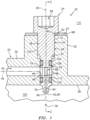
FIG. 1 is a sectional illustration of a portion of an assembly for an internal combustion engine. -
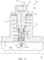
FIG. 2 is a sectional illustration of a portion of the engine assembly taken along line 2-2 inFIG. 1 . -
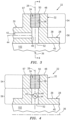
FIG. 3 is a sectional illustration of a portion of an engine structure for the engine assembly. -
FIG. 4 is a section illustration of a portion of the engine structure taken along line 4-4 inFIG. 3 . -
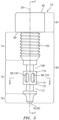
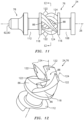
FIG. 5 is an illustration of a fuel injector. -
FIG. 6A is an illustration of a head of the fuel injector with an internal wrenching feature. -
FIG. 6B is an illustration of the fuel injector head with an external wrenching feature. -
FIG. 7 is a sectional illustration of the fuel injector taken along line 7-7 inFIG. 5 . -
FIG. 8 is a cross-sectional illustration of the fuel injector taken along line 8-8 inFIG. 5 . -
FIG. 9 is a perspective illustration of a portion of the fuel injector configured with a set of straight struts. -
FIG. 10 is a perspective cross-sectional illustration of a portion of the fuel injector taken along line 10-10 inFIG. 9 . -
FIG. 11 is an illustration of a portion of the fuel injector configured with a set of non-straight struts. -
FIG. 12 is a perspective cross-sectional illustration of a portion of the fuel injector taken along line 12-12 inFIG. 11 . -
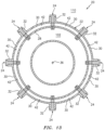
FIG. 13 is a cross-sectional illustration of the engine assembly configured with a plurality of the fuel injectors. -
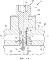
FIG. 14 is a sectional illustration of a portion of the engine assembly ofFIG. 13 . -
FIG. 15 is a schematic illustration of another engine assembly configured with a plurality of the fuel injectors. -
FIG. 16 is a perspective, cutaway illustration of a portion of the engine assembly ofFIG. 15 . -
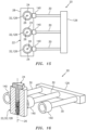
FIG. 17 is a perspective, sectional illustration of another portion of the engine assembly ofFIG. 15 . -
FIG. 18 is a schematic side illustration of a single spool, radial-flow turbojet turbine engine. -
FIGS. 1 and2 are sectional illustrations of anassembly 20 for an internal combustion (IC) engine. For ease of description, this engine may be described below as a gas turbine engine. The present disclosure, however, is not limited to gas turbine engine applications. For example, the engine may alternatively be configured as a reciprocating piston engine, a rotary engine, or any other type of engine where fuel is continuously or periodically injected into chamber or another internal volume (e.g., an open space) for combustion. - The
engine assembly 20 includes astatic engine structure 22; see alsoFIG. 13 . Theengine assembly 20 also includes a removable /modular fuel injector 24 with alongitudinal centerline 26; e.g., a straight centerline axis. - Referring to
FIGS. 3 and 4 , theengine structure 22 may be configured as any stationary part of the engine that is proximate thefuel injector 24. Theengine structure 22 ofFIGS. 3 and 4 , for example, may be configured as an engine casing such as, but not limited to, a combustor section case, a diffuser case and/or a combustor wall (e.g., a liner wall, a bulkhead wall, etc.). Theengine structure 22 ofFIGS. 3 and 4 includes acase wall 28, afuel conduit 30, afuel injector boss 32 and afuel injector aperture 34. - The
case wall 28 may be configured as an arcuate or tubular member. Thecase wall 28 ofFIGS. 3 and 4 , for example, extends axially along acenterline axis 36 of theengine structure 22, which enginestructure centerline axis 36 may be coaxial with a centerline axis and/or a rotational axis of the engine. Thecase wall 28 extends circumferentially about (e.g., partially or completely around) the enginestructure centerline axis 36. Thecase wall 28 extends radially between a first (e.g., exterior, outer)side 38 of thecase wall 28 and a second (e.g., interior, inner)side 40 of thecase wall 28, which case wallsecond side 40 is radially opposite the case wallfirst side 38. - The
fuel conduit 30 ofFIG. 3 is configured as, or may be part of, a fuel supply for thefuel injector 24. Thefuel conduit 30, for example, may be or may be part of a fuel supply tube, a fuel inlet manifold and/or a fuel distribution manifold. Thefuel conduit 30 is arranged at and/or is connected to the case wallfirst side 38. Thefuel conduit 30 is configured with an internalfuel supply passage 42. Thissupply passage 42 may be formed by an internal bore and/or channel within thefuel conduit 30. Thesupply passage 42 extends within and/or through thefuel conduit 30 along a (e.g., curved and/or straight) centerline 44 of the supply passage 42 (laterally relative to thecenterline 26; seeFIG. 1 ) to asupply passage orifice 46, whichsupply passage centerline 44 may also be a centerline of thefuel conduit 30. - The
injector boss 32 is configured for mounting thefuel injector 24 with theengine structure 22; seeFIGS. 1 and2 . Theinjector boss 32 ofFIGS. 3 and 4 , for example, is a tubular member configured to receive thefuel injector 24. Theinjector boss 32 is arranged at and/or is connected to the case wallfirst side 38. Theinjector boss 32 ofFIGS. 3 and 4 , for example, projects longitudinally out from thecase wall 28 and itsfirst side 38 along thecenterline 26 to adistal end 48 of theinjector boss 32. - The
injector aperture 34 may be formed by an internal bore and/or channel within theengine structure 22. Theinjector aperture 34 extends longitudinally along thecenterline 26 through theengine structure 22 to and between a first (e.g., exterior, outer) end 50 of theinjector aperture 34 and a second (e.g., interior, inner) end 52 of theinjector aperture 34, which aperturesecond end 52 is longitudinally opposite the aperturefirst end 50. The aperturefirst end 50 is arranged at the injector bossdistal end 48. The aperturesecond end 52 is arranged at the case wallsecond side 40. Theinjector aperture 34 ofFIGS. 3 and 4 thereby extends longitudinally along the centerline 26 from the injector bossdistal end 48, through theinjector boss 32 and thecase wall 28, to the case wallsecond side 40. - The
injector aperture 34 may include a threadedportion 54 and anon-threaded portion 56. The aperture threadedportion 54 is a tapped portion of asidewall 58 of theinjector aperture 34. The aperture threadedportion 54 is disposed at (e.g., on, adjacent or proximate) the aperturefirst end 50. The aperturenon-threaded portion 56 is an untapped (e.g., smooth, cylindrical) portion of theaperture sidewall 58. The aperturenon-threaded portion 56 is disposed at the aperturesecond end 52. - The
passage orifice 46 is disposed along an intermediate region of theinjector aperture 34. Thepassage orifice 46, for example, is located longitudinally (e.g., midway) between the aperturefirst end 50 and the aperturesecond end 52 along thecenterline 26. Thepassage orifice 46 ofFIGS. 3 and 4 , in particular, is disposed in the untapped portion of the aperture sidewall 58 - in the aperturenon-threaded portion 56. Thesupply passage 42 is thereby fluidly coupled with theinjector aperture 34 and itsnon-threaded portion 56. - Referring to
FIG. 5 , thefuel injector 24 may be configured as a fuel injector bolt or plug. Thefuel injector 24 ofFIG. 5 , in particular, extends longitudinally along thecenterline 26 between and to a first (e.g., exterior, outer) end 60 of thefuel injector 24 and a second (e.g., interior, inner) end 62 of thefuel injector 24, which injector second end 62 is longitudinally opposite the injectorfirst end 60. Thefuel injector 24 ofFIG. 5 includes afuel injector head 64 and afuel injector base 66, where theinjector head 64 may be a head of the fuel injector bolt / plug and theinjector base 66 may be a shank of the fuel injector bolt / plug. - The
injector head 64 is connected to theinjector base 66 and arranged at the injectorfirst end 60. Referring toFIGS. 6A and 6B , theinjector head 64 may be configured with awrenching feature 68, 68'. Theinjector head 64 ofFIGS. 6A and7 , for example, is configured with arecess 70 for receiving and mating with a tool (not shown) such as, but not limited to, a hex-head tool (e.g., an Allen wrench or drive). Therecess 70 projects longitudinally along thecenterline 26 partially into theinjector head 64 from the injectorfirst end 60 to anend 72 of thewrenching feature 68. Therecess 70 ofFIG. 6A has a polygonal cross-sectional geometry such as, but not limited to, a hexagonal cross-sectional geometry when viewed, for example, in a plane perpendicular to thecenterline 26; e.g., plane ofFIG. 6A . While the wrenchingfeature 68 is described above as an internal wrenching feature, theinjector head 64 may also or alternatively be configured with an external wrenching feature 68'. For example, referring toFIG. 6B , an exterior of theinjector head 64 may be configured one or more flats (e.g., planer surfaces) to provide thehead 64 with a polygonal cross-sectional geometry. - Referring to
FIG. 5 , theinjector base 66 projects longitudinally along the centerline 26 from theinjector head 64 to the injector second end 62. Theinjector base 66 ofFIG. 5 includes a (e.g., threaded)fuel injector mount 74, afuel coupler 76 and afuel nozzle 78. - The injector mount 74 is longitudinally between and connected to the
injector head 64 and thefuel coupler 76. The injector mount 74 ofFIG. 5 , for example, extends longitudinally along thecenterline 26 to and between theinjector head 64 and thefuel coupler 76. The injector mount 74 may be a solid portion of thefuel injector 24; see alsoFIG. 7 . Theinjector mount 74, for example, may be configured without any pathways through which fluid (e.g., fuel) may to travel (e.g., laterally and/or longitudinally) thereacross. More particularly, thefuel injector 24 ofFIG. 5 is configured without any apertures, bores, channels, etc. extending laterally and/or longitudinally through theinjector mount 74. - An exterior of the
injector mount 74 is configured with threads for mating with the aperture threadedportion 54; seeFIGS. 1 and2 . The threaded exterior of theinjector mount 74 may be laterally (e.g., radially relative to the centerline 26) recessed from the exterior of theinjector head 64 such that a (e.g., annular)head shoulder 80 extends laterally between the exteriors and circumferentially around thecenterline 26. - Referring to
FIG. 7 , thefuel coupler 76 is longitudinally between and connected to theinjector mount 74 and thefuel nozzle 78. Thefuel coupler 76 ofFIG. 7 , for example, extends longitudinally along thecenterline 26 to and between theinjector mount 74 and thefuel nozzle 78. Thefuel coupler 76 is configured with a lateral width 82 (e.g., a diameter) that is less than a lateral width 84 (e.g., a diameter) of theinjector mount 74. - The
fuel coupler 76 includes one or more ports 86 (e.g., apertures, windows, pass-throughs, etc.) and an internal volume 88 (e.g., a plenum, a chamber, etc.). Referring toFIG. 8 , theports 86 are arranged circumferentially about thecenterline 26. Eachport 86 provides a flowpath from an exterior of thefuel coupler 76 into theinternal volume 88. Eachport 86 ofFIG. 8 , for example, projects laterally (e.g., radially relative to the centerline 26) into thefuel coupler 76 from the exterior of thefuel coupler 76 to theinternal volume 88. Theinternal volume 88 is laterally and longitudinally within thefuel coupler 76. Theinternal volume 88, for example, may be an internal bore within thefuel coupler 76. - Referring to
FIG. 7 , thefuel nozzle 78 is connected to thefuel coupler 76. Thefuel nozzle 78 ofFIG. 7 , for example, projects longitudinally along the centerline 26 from thefuel coupler 76 to a distal end 90 (e.g., a tip) of thefuel nozzle 78 at the injector second end 62. Thefuel nozzle 78 is configured with a lateral width 92 (e.g., a diameter) that is different (e.g., less) than thecoupler lateral width 82 at the distal end 90; however, the present disclosure is not limited thereto. - The
fuel nozzle 78 is configured with a nozzle passage 94 (e.g., a fuel passage) and anozzle orifice 96. An internal bore of thefuel injector 24 at least partially (or completely) forms thenozzle passage 94. Thenozzle passage 94 and its internal bore extend longitudinally along the centerline 26 from theinternal volume 88 within thefuel coupler 76 to thenozzle orifice 96 at the injector second end 62; e.g., a distal end / tip of thefuel nozzle 78. Thenozzle passage 94 may thereby extend longitudinally along thecenterline 26 out of thefuel coupler 76 and then through thefuel nozzle 78 to thenozzle orifice 96. Thenozzle orifice 96 provides an outlet from thenozzle passage 94 and, more generally, thefuel injector 24 and itsnozzle 78. - Referring to
FIGS. 1 and2 , thefuel injector 24 is mated with (e.g., disposed and/or threaded into) theinjector aperture 34. For example, during assembly, thefuel nozzle 78 is inserted longitudinally into theinjector aperture 34 at the aperturefirst end 50. Thefuel nozzle 78 is moved longitudinally through the aperture threadedportion 54 and into the aperturenon-threaded portion 56. The external threads of theinjector mount 74 are mated with the internal threads of the aperture threadedportion 54. Thefuel injector 24 is threaded (e.g., screwed) into theinjector aperture 34 using a tool (not shown) until, for example, thehead shoulder 80 is longitudinally abutted and preloaded indirectly against asurface 97 at the bossdistal end 60 through, for example, awasher 98, or directly against the bossdistal end surface 97 where, for example, thewasher 98 is omitted. Thefuel injector 24 is thereby removably attached to theengine structure 22 by a threaded interface between the interior threads on thesidewall 58 of the aperture threadedportion 54 and the exterior threads on theinjector mount 74. - In the assembled position of
FIG. 1 , thepassage orifice 46 is aligned with thefuel coupler 76 and at least one of itsports 86. One of theports 86, for example, may at least partially (or completely) longitudinally overlap and may at least partially (or completely) circumferentially overlap thepassage orifice 46 to provide a (e.g., unobstructed, or only partially obstructed) fluid coupling between thesupply passage 42 and theinternal volume 88. Note, theports 86 may be configured with the fuel coupling (e.g., sized and spaced around the centerline 26) such that, for example, at least one of theseports 86 is at least partially (or completely) aligned with thepassage orifice 46 no matter how thefuel nozzle 78 is clocked about thecenterline 26 within theinjector aperture 34. - The
injector mount 74 and/or thefuel coupler 76 may be arranged completely within theinjector aperture 34. Thefuel nozzle 78 may be arranged (e.g., partially or completely) within and/or outside of theinjector aperture 34. More particularly, thefuel nozzle 78 ofFIGS. 1 and2 projects longitudinally out from theinjector aperture 34, away from the case wallsecond side 40 and into a plenum 102 (e.g., an air passage) within theengine structure 22. - With the above configuration, the
fuel injector 24 may be installed with theengine structure 22 and removed from theengine structure 22 from an exterior of theengine structure 22. Assembly personnel, maintenance personnel and/or inspection personnel may thereby install, replace and/or service thefuel injector 24 without requiring disassembly and/or removal of theengine structure 22 nor access to an interior of theengine structure 22.Fuel injectors 24 with, for example,different fuel coupler 76 configurations,fuel nozzle 78 configurations, etc. may be more easily swapped. The plug-and-play operation of thefuel nozzle 78 reduces complexity of the fuel delivery system. For example, a single step of mating thefuel injector 24 with theengine structure 22 may (A) fluidly couple thefuel injector 24 with thefuel conduit 30 as well as (B) position thefuel nozzle 78 for operation. Furthermore, the bolt-like design of thefuel injector 24 may simplify the mechanical connection between thefuel injector 24 and theengine structure 22. - Referring to
FIG. 1 , during engine operation, (e.g., liquid) fuel is directed into thesupply passage 42 from a fuel source (not shown) such as, but not limited to, a fuel reservoir (e.g., a tank). At least a portion (or all) of the fuel within thesupply passage 42 is directed through a respective one of theports 86 and into theinternal volume 88. At least a portion (or all) of the fuel within theinternal volume 88 is directed into thenozzle passage 94. This fuel flows through thenozzle passage 94 and out of thefuel nozzle 78 through thenozzle orifice 96 and into the plenum 102 (e.g., the air passage) within theengine structure 22. The fuel within theplenum 102 may be mixed with air (e.g., compressed air) for subsequent combustion in, for example, another downstream volume (e.g., a combustion chamber) within the engine or alternatively within theplenum 102 where, for example, theplenum 102 is a combustion chamber. - In some embodiments, referring to
FIG. 1 , thefuel injector 24 may be configured with one or moreannular seal elements seal element ports 86 and thepassage orifice 46 ofFIG. 1 are positioned longitudinally along thecenterline 26 between the first (e.g., outer)seal element 104 and the second (e.g., inner)seal element 106. - The
first seal element 104 is seated in an annular first (e.g., outer) seal receptacle 108 (e.g., a notch, a groove, a channel, etc.) in theinjector base 66; see alsoFIGS. 5 and7 . Thefirst seal receptacle 108 ofFIG. 1 , in particular, is located in an outer portion of thefuel coupler 76. However, in other embodiments, thefirst seal receptacle 108 may be located in an inner portion of theinjector mount 74, or in another portion of thefuel injector 24 and itsbase 66 longitudinally between thefuel coupler 76 and theinjector mount 74. - The
first seal element 104 is laterally engaged with theinjector base 66 and theaperture sidewall 58 in the aperturenon-threaded portion 56. Thefirst seal element 104 may thereby form a seal interface between thefuel injector 24 and theengine structure 22 such that the fuel, for example, does not leak (e.g., in an outward direction; vertically up inFIG. 1 ) between theengine assembly elements external plenum 110. - The
second seal element 106 is seated in an annular second (e.g., inner) seal receptacle 112 (e.g., a notch, a groove, a channel, etc.) in theinjector base 66; see alsoFIGS. 5 and7 . Thesecond seal receptacle 112 ofFIG. 1 , in particular, is located in an inner portion of thefuel coupler 76. However, in other embodiments, thesecond seal receptacle 112 may be located in an outer portion of thefuel nozzle 78, or in another portion of thefuel injector 24 and itsbase 66 longitudinally between thefuel coupler 76 and thefuel nozzle 78. - The
second seal element 106 is laterally engaged with theinjector base 66 and theaperture sidewall 58 in the aperturenon-threaded portion 56. Thesecond seal element 106 may thereby form a seal interface between thefuel injector 24 and theengine structure 22 such that the fuel, for example, does not leak (e.g., in an inward direction; vertically down inFIG. 1 ) between theengine assembly elements internal plenum 102. - In some embodiments, referring to
FIGS. 5 ,7 and8 , thefuel coupler 76 may include atubular sidewall 114. Thefuel coupler 76 may also include one ormore end walls tubular sidewall 114 ofFIG. 5 and7 is connected to and extends longitudinally along thecenterline 26 to and between the first (e.g., outer)end wall 116 and the second (e.g., inner)end wall 118. Referring toFIG. 8 , thetubular sidewall 114 extends circumferentially around thecenterline 26 and theinternal volume 88. Thetubular sidewall 114 includes one or more apertures 120; e.g., through-holes, slots, etc. Each of these apertures 120 extends laterally (e.g., radially relative to the centerline 26) through thetubular sidewall 114. Each of the apertures 120 extends longitudinally along thecenterline 26 between and to the fuelcoupler end walls ports 86 in thefuel coupler 76. Theinternal volume 88 may be laterally bounded by thetubular sidewall 114, and longitudinally bounded between thefirst end wall 116 and thesecond end wall 118 along thecenterline 26. - In some embodiments, referring to
FIGS. 9-12 , thefuel coupler 76 may include one ormore struts 122; e.g., spars, vanes, foils, posts, etc. Thefuel coupler 76 may also include the one ormore end walls struts 122 ofFIGS. 9-12 are arranged circumferentially about thecenterline 26 and theinternal volume 88. Each of thestruts 122 is connected to and extends longitudinally along thecenterline 26 between and to thefirst end wall 116 and thesecond end wall 118. Each of thestruts 122 is circumferentially spaced from its circumferentially neighboring struts 122. The space between each circumferentially adjacent pair of thestruts 122 may be / form a respective one of theports 86. More particularly, eachport 86 extends circumferentially between and to a respective circumferentially adjacent pair of thestruts 122. Eachport 86 extends longitudinally along thecenterline 26 between and to the fuelcoupler end walls internal volume 88 may be laterally bounded by thestruts 122, and longitudinally bounded between thefirst end wall 116 and thesecond end wall 118 along thecenterline 26. - Each of the
struts 122 have arespective strut centerline 124. Each of thestruts 122 extends along itsstrut centerline 124 between and to the fuelcoupler end walls FIGS. 9 and 10 , at least a portion or an entirety of one or more or all of thestrut centerlines 124 may each follow a straight trajectory. Alternatively, referring toFIGS. 11 and 12 , at least a portion or the entirety of one or more or all of thestrut centerlines 124 may each follow a non-straight trajectory. Examples of the non-straight trajectory include, but are not limited to, a curved trajectory, a spline trajectory, a spiral trajectory and a helical trajectory. - Each of the
struts 122 has a cross-sectional geometry when viewed, for example, in a plane perpendicular to thecenterline 26 and/or itsrespective strut centerline 124. This cross-sectional geometry may be an elongated cross-sectional geometry as shown, for example, inFIGS. 10 and12 . The cross-sectional geometry, for example, may have a double-tapered shape, an airfoil shape, an oval shape or a diamond shape. The present disclosure, however, is not limited to the foregoing exemplary elongated shapes nor tostruts 122 with elongated cross-sectional geometries. For example, in other embodiments, the cross-sectional shape may be circular shaped or square shaped. - Providing the
struts 122 ofFIGS. 9-12 may increase circumferential widths of theports 86. Increasing the port circumferential widths may further reduce a chance of one or more portions of the fuel coupler 76 (e.g., one or more of the struts 122) partially blocking (e.g., circumferentially overlapping) thesupply orifice 46. In addition, the struts 122 (e.g., seeFIGS. 11 and 12 ) may be configured to at least partially turn the fuel flowing laterally out of thesupply passage 42 and itssupply orifice 46 longitudinally along thecenterline 26 into thenozzle passage 94. Thestruts 122 may thereby reduce fuel drag through the interface between thefuel conduit 30 and thefuel injector 24. - In some embodiments, referring to
FIG. 13 , theengine assembly 20 may include a plurality of thefuel injectors 24. Thesefuel injectors 24 may be arranged circumferentially about the enginestructure centerline axis 36 in, for example, an annular array. Each of thefuel injectors 24 may be configured as described above. Theengine structure 22 may also be generally configured as described above. However, theengine structure 22 may include a plurality of thefuel conduits 30 and a plurality of theinjector bosses 32, where eachinjector boss 32 is configured to mount a respective one of thefuel injectors 24 with theengine structure 22. - The
fuel conduits 30 may be configured to collectively form a fuel supply (e.g., a manifold) for thefuel injectors 24. Eachfuel conduit 30 ofFIG. 13 , for example, is arranged between a respective circumferentially adjacent pair of thefuel injectors 24. Referring toFIG. 14 , eachinjector boss 32 may be arranged circumferentially between and connected to respective circumferentially adjacent pair of thefuel conduits 30. Thus, eachinjector aperture 34 and therespective fuel injector 24 received therein is fluidly coupled with a respective pair of thesupply passages 42. - In some embodiments, each
fuel injector 24 may be configured as a monolithic body. Eachfuel injector 24 and itselements engine structure 22 may also or alternatively be configured as a monolithic body. Theengine structure 22 and each of itselements - In some embodiments, referring to
FIGS. 15 and 16 , thefuel conduits 30 may be formed discrete from theengine structure 22. Each of thefuel conduits 30, for example, may be configured as a discrete line (e.g., pipe, hose, etc.) that fluidly couples and extends between a manifold 126 and a respective one of theinjector bosses 32. - Referring to
FIG. 17 , eachinjector boss 32 may be configured as a fuel injector fuel supply apparatus 128; e.g., a fitting, a mount, a coupler, etc. Eachinjector boss 32, for example, may include a boss base 130 (e.g., a tubular fitting base), a boss coupler 132 (e.g., a fitting coupler) and asupply passage 134. Theboss coupler 132 projects laterally (e.g., radially relative to the centerline 26) out from an exterior of theboss base 130 to adistal end 136 of theboss coupler 132. Thesupply passage 134 extends laterally through the injector boss 32 (the fuel supply apparatus 128) from aninlet passage orifice 138 to theoutlet passage orifice 46, where theinlet passage orifice 138 is located at the boss couplerdistal end 136. Theboss coupler 132 may thereby be configured as a male fitting such as, but not limited to, a nipple. - Each
fuel conduit 30 may include aconduit coupler 140. Theconduit coupler 140 ofFIG. 17 includes a counterbore (or a bore) configured to receive theboss coupler 132. Thisconduit coupler 140 may thereby be configured as a female fitting such as, but not limited to, a receptacle. Theconduit coupler 140 is configured to mate with theboss coupler 132. More particularly, theboss coupler 132 ofFIG. 17 projects into theconduit coupler 140 to provide a fluid coupling between theelements supply passages couplers -
FIG. 18 schematically illustrates a single spool, radial-flowturbojet turbine engine 142 with which theengine assembly 20 may be included. Thisturbine engine 142 may be configured for propelling an unmanned aerial vehicle (UAV), a drone, or any other manned or unmanned aircraft or self-propelled projectile. In the specific embodiment ofFIG. 18 , theturbine engine 142 includes anupstream inlet 144, a (e.g., radial)compressor section 146, a combustor section 148 with a (e.g., annular) combustor 149 and a (e.g., annular)combustion chamber 150, a (e.g., radial)turbine section 151 and adownstream exhaust 152 fluidly coupled in series. Acompressor rotor 154 in thecompressor section 146 is coupled with aturbine rotor 156 in theturbine section 151 by ashaft 158, which rotates about the centerline /rotational axis 36 of theturbine engine 142. - The
engine assembly 20 may be configured for a gas turbine engine as described above. This gas turbine engine may be configured for propulsion and/or power generation. The gas turbine engine may be a geared turbine engine which includes a gear train connecting one or more shafts to one or more rotors in a fan section, a compressor section and/or any other engine section. Alternatively, the gas turbine engine may be a direct-drive turbine engine configured without a gear train. The gas turbine engine may be configured as a single spool or a multi-spool turbine engine. The gas turbine engine may be configured as a turbofan engine, a turbojet engine, a propfan engine, a pusher fan engine, an auxiliary power unit (APU), an industrial turbine engine or any other type of gas turbine engine. The present disclosure, however, is not limited to any particular types or configurations of gas turbine engines. Furthermore, theengine assembly 20 may alternatively be configured with various other types of internal combustion engines. For example, theengine structure 22 may be configured as a case, a block, a head or another component of a reciprocating piston engine, a rotary engine, or any other type of engine where fuel is continuously or periodically injected into chamber or another internal volume for combustion. - While various embodiments of the present disclosure have been described, it will be apparent to those of ordinary skill in the art that many more embodiments and implementations are possible within the scope of the disclosure. For example, the present disclosure as described herein includes several aspects and embodiments that include particular features. Although these features may be described individually, it is within the scope of the present disclosure that some or all of these features may be combined with any one of the aspects and remain within the scope of the disclosure. Accordingly, the present disclosure is not to be restricted except in light of the attached claims and their equivalents.
Claims (15)
- An assembly for an engine, comprising:a fuel supply apparatus (128) comprising an injector aperture (34) and a fuel supply passage (42), the injector aperture extending longitudinally through the fuel supply apparatus along a centerline (26), the fuel supply passage extending laterally within the fuel supply apparatus to the injector aperture; anda fuel injector (24) mated with the injector aperture, the fuel injector comprising a nozzle passage (94) and a nozzle orifice (96), the nozzle passage extending longitudinally along the centerline within the fuel injector to the nozzle orifice, and the nozzle passage fluidly coupled with the fuel supply passage.
- The assembly of claim 1, comprising at least one of:a fuel conduit (30) attached to the fuel supply apparatus, the fuel conduit configured to provide fuel to the fuel injector through the fuel supply passage; oran engine structure wall, the fuel supply apparatus configured as a boss (32) projecting longitudinally out from the engine structure wall.
- The assembly of any preceding claim, wherein:the fuel injector (24) includes a fuel nozzle (78) and a fuel coupler (76);the fuel nozzle (78) includes the nozzle passage (94) and the nozzle orifice (96); andthe fuel coupler (76) is within the injector aperture (34) adjacent the fuel supply passage (42), and the fuel coupler (76) is configured to fluidly couple the fuel supply passage (42) with the nozzle passage (94).
- The assembly of claim 3, wherein:the fuel coupler (76) includes a tubular sidewall (114) and a chamber (88) within the tubular sidewall (114);a port (86) extends laterally through the tubular sidewall (114), and the port (86) is at least partially aligned with an orifice (46) to the fuel supply passage (42); andthe chamber (88) is fluidly coupled with and between the port (86) and the nozzle passage (94).
- The assembly of claim 3, wherein:the fuel coupler (76) includes a first end wall (116), a second end wall (118) and a plurality of struts (122); andthe plurality of struts (122) are arranged circumferentially about the centerline (26), and the plurality of struts (122) are connected to and extend longitudinally along the centerline (26) between the first end wall (116) and the second end wall (118).
- The assembly of claim 5, wherein:the fuel coupler (76) includes a plurality of ports (86) and an internal chamber (88);each of the plurality of ports (86) is formed circumferentially between a respective adjacent pair of the plurality of struts (122), and a first of the plurality of ports (86) is at least partially aligned with an orifice (46) to the fuel supply passage (42);the plurality of struts (122) are arranged circumferentially around the internal chamber (88); andthe internal chamber (88) is fluidly coupled with and between the plurality of ports (86) and the nozzle passage (94).
- The assembly of claim 5 or 6, wherein a first of the plurality of struts (122) has an elongated cross-sectional geometry
- The assembly of claim 5 or 6, wherein a first of the plurality of struts (122) has and extends along a strut centerline (124) between the first end wall (116) and the second end wall (118), and the strut centerline (124) follows a straight trajectory
- The assembly of claim 5 or 6, wherein a first of the plurality of struts (122) has and extends along a strut centerline (124) between the first end wall (116) and the second end wall (118) and the strut centerline (124) follows a non-straight trajectory.
- A fuel injector for an engine, comprising:a fuel injector body (24) extending longitudinally along a centerline (26) between a fuel injector first end (60) and a fuel injector second end (62), the fuel injector body including a mount (74), a fuel nozzle (78), a fuel coupler (76) and a nozzle passage (94);the mount (74) comprising a threaded exterior;the fuel nozzle (78) comprising a nozzle orifice (96), the nozzle passage extending longitudinally along the centerline within the fuel injector body to the nozzle orifice, and the nozzle orifice disposed at the fuel injector second end; andthe fuel coupler arranged longitudinally along the centerline between the mount and the fuel nozzle, the fuel coupler comprising a port (86) and an internal volume (88), the port extending laterally into the fuel injector body to the internal volume, and the internal volume fluidly coupled with and between the port and the nozzle passage.
- The fuel injector of claim 10, whereinthe fuel coupler includes a tubular sidewall (114) extending circumferentially around the internal volume (88); andthe port (86) extends laterally through the tubular sidewall.
- The fuel injector of claim 10 or 11, wherein:the fuel coupler includes a first end wall (116), a second end wall (118) and a plurality of struts (122);the plurality of struts are arranged circumferentially about the centerline and the internal volume, and the plurality of struts are connected to and extend longitudinally along the centerline between the first end wall (116) and the second end wall (118); andthe port is formed circumferentially between a respective adjacent pair of the plurality of struts.
- The fuel injector of claim 12, wherein a first of the plurality of struts has a double-tapered cross-sectional geometry.
- The fuel injector of claim 12, wherein a first of the plurality of struts (122) follows a straight trajectory.
- The fuel injector of claim 12, wherein a first of the plurality of struts (122) follows a non-straight trajectory.
Applications Claiming Priority (2)
| Application Number | Priority Date | Filing Date | Title |
|---|---|---|---|
| US17/214,730 US20220307694A1 (en) | 2021-03-26 | 2021-03-26 | Modular injector bolt for an engine |
| EP22164852.0A EP4063734B1 (en) | 2021-03-26 | 2022-03-28 | Assembly for a gas turbine engine comprisng a fuel injector |
Related Parent Applications (2)
| Application Number | Title | Priority Date | Filing Date |
|---|---|---|---|
| EP22164852.0A Division EP4063734B1 (en) | 2021-03-26 | 2022-03-28 | Assembly for a gas turbine engine comprisng a fuel injector |
| EP22164852.0A Division-Into EP4063734B1 (en) | 2021-03-26 | 2022-03-28 | Assembly for a gas turbine engine comprisng a fuel injector |
Publications (1)
| Publication Number | Publication Date |
|---|---|
| EP4350137A2 true EP4350137A2 (en) | 2024-04-10 |
Family
ID=80979049
Family Applications (2)
| Application Number | Title | Priority Date | Filing Date |
|---|---|---|---|
| EP24160061.8A Pending EP4350137A2 (en) | 2021-03-26 | 2022-03-28 | Assembly for a gas turbine engine comprisng a fuel injector |
| EP22164852.0A Active EP4063734B1 (en) | 2021-03-26 | 2022-03-28 | Assembly for a gas turbine engine comprisng a fuel injector |
Family Applications After (1)
| Application Number | Title | Priority Date | Filing Date |
|---|---|---|---|
| EP22164852.0A Active EP4063734B1 (en) | 2021-03-26 | 2022-03-28 | Assembly for a gas turbine engine comprisng a fuel injector |
Country Status (2)
| Country | Link |
|---|---|
| US (1) | US20220307694A1 (en) |
| EP (2) | EP4350137A2 (en) |
Family Cites Families (11)
| Publication number | Priority date | Publication date | Assignee | Title |
|---|---|---|---|---|
| US4057371A (en) * | 1974-05-03 | 1977-11-08 | Norwalk-Turbo Inc. | Gas turbine driven high speed centrifugal compressor unit |
| GB9818160D0 (en) * | 1998-08-21 | 1998-10-14 | Rolls Royce Plc | A combustion chamber |
| US20100071377A1 (en) * | 2008-09-19 | 2010-03-25 | Fox Timothy A | Combustor Apparatus for Use in a Gas Turbine Engine |
| JP4797079B2 (en) * | 2009-03-13 | 2011-10-19 | 川崎重工業株式会社 | Gas turbine combustor |
| US9010120B2 (en) * | 2011-08-05 | 2015-04-21 | General Electric Company | Assemblies and apparatus related to integrating late lean injection into combustion turbine engines |
| US20130104553A1 (en) * | 2011-11-01 | 2013-05-02 | General Electric Company | Injection apparatus |
| US9052115B2 (en) * | 2012-04-25 | 2015-06-09 | General Electric Company | System and method for supplying a working fluid to a combustor |
| US9366443B2 (en) * | 2013-01-11 | 2016-06-14 | Siemens Energy, Inc. | Lean-rich axial stage combustion in a can-annular gas turbine engine |
| EP2808611B1 (en) * | 2013-05-31 | 2015-12-02 | Siemens Aktiengesellschaft | Injector for introducing a fuel-air mixture into a combustion chamber |
| US9400113B2 (en) * | 2014-06-12 | 2016-07-26 | Kawasaki Jukogyo Kabushiki Kaisha | Multifuel gas turbine combustor |
| US11060460B1 (en) * | 2019-04-01 | 2021-07-13 | Marine Turbine Technologies, LLC | Fuel distribution system for gas turbine engine |
-
2021
- 2021-03-26 US US17/214,730 patent/US20220307694A1/en active Pending
-
2022
- 2022-03-28 EP EP24160061.8A patent/EP4350137A2/en active Pending
- 2022-03-28 EP EP22164852.0A patent/EP4063734B1/en active Active
Also Published As
| Publication number | Publication date |
|---|---|
| US20220307694A1 (en) | 2022-09-29 |
| EP4063734B1 (en) | 2024-04-24 |
| EP4063734A1 (en) | 2022-09-28 |
Similar Documents
| Publication | Publication Date | Title |
|---|---|---|
| EP2224102B1 (en) | A coolable shroud seal segment assembly of a gas turbine engine | |
| EP1489269B1 (en) | Methods and apparatus for injecting cleaning fluids into combustors | |
| EP3109548B1 (en) | Combustion system with combustor dome integrated fuel manifold | |
| EP1908940B1 (en) | Multi-conduit fuel manifold and method of manufacture | |
| EP3521591B1 (en) | Segmented internal fuel manifold | |
| US11525578B2 (en) | Dynamics-mitigating adapter for bundled tube fuel nozzle | |
| EP3358140B1 (en) | Fitting for multiwall tube | |
| US9664392B2 (en) | Bundled tube fuel injector with outer shroud and outer band connection | |
| CA2770858C (en) | Fuel manifold with jumper tubes | |
| US10422533B2 (en) | Combustor with axially staged fuel injector assembly | |
| EP3039268B1 (en) | Fuel manifold for a gas turbine engine and manufacturing method thereof | |
| US11788723B2 (en) | Fuel injection for integral combustor and turbine vane | |
| EP4063734B1 (en) | Assembly for a gas turbine engine comprisng a fuel injector | |
| US10240793B2 (en) | Single-fitting, dual-circuit fuel nozzle | |
| US11684954B2 (en) | Removing debris from an engine component | |
| EP4230915A1 (en) | Fuel injector with splash plate for an engine | |
| EP3586061B1 (en) | Endcover assembly for a combustor | |
| KR102570813B1 (en) | Fuel supply assembly and related methods | |
| EP4015909A1 (en) | Gap filler for a fuel system gallery | |
| CN115682028A (en) | Cartridge tip for a turbomachine combustor | |
| CN116772238A (en) | Dome-deflector joint cooling arrangement |
Legal Events
| Date | Code | Title | Description |
|---|---|---|---|
| PUAI | Public reference made under article 153(3) epc to a published international application that has entered the european phase |
Free format text: ORIGINAL CODE: 0009012 |
|
| STAA | Information on the status of an ep patent application or granted ep patent |
Free format text: STATUS: THE APPLICATION HAS BEEN PUBLISHED |
|
| AC | Divisional application: reference to earlier application |
Ref document number: 4063734 Country of ref document: EP Kind code of ref document: P |
|
| AK | Designated contracting states |
Kind code of ref document: A2 Designated state(s): AL AT BE BG CH CY CZ DE DK EE ES FI FR GB GR HR HU IE IS IT LI LT LU LV MC MK MT NL NO PL PT RO RS SE SI SK SM TR |
|
| PUAL | Search report despatched |
Free format text: ORIGINAL CODE: 0009013 |