EP4350135A2 - Overspeed and/or overtorque protection for hybrid electric aircraft propulsion system - Google Patents
Overspeed and/or overtorque protection for hybrid electric aircraft propulsion system Download PDFInfo
- Publication number
- EP4350135A2 EP4350135A2 EP23201463.9A EP23201463A EP4350135A2 EP 4350135 A2 EP4350135 A2 EP 4350135A2 EP 23201463 A EP23201463 A EP 23201463A EP 4350135 A2 EP4350135 A2 EP 4350135A2
- Authority
- EP
- European Patent Office
- Prior art keywords
- hep
- power
- electric motor
- protection module
- epc
- Prior art date
- Legal status (The legal status is an assumption and is not a legal conclusion. Google has not performed a legal analysis and makes no representation as to the accuracy of the status listed.)
- Pending
Links
- 239000000446 fuel Substances 0.000 claims abstract description 5
- 238000004891 communication Methods 0.000 claims abstract description 4
- 238000000034 method Methods 0.000 claims description 24
- 230000004044 response Effects 0.000 claims description 11
- 238000012544 monitoring process Methods 0.000 claims description 4
- 238000012545 processing Methods 0.000 description 8
- 238000002485 combustion reaction Methods 0.000 description 4
- 238000010586 diagram Methods 0.000 description 4
- 238000005516 engineering process Methods 0.000 description 4
- 230000009467 reduction Effects 0.000 description 3
- 239000000567 combustion gas Substances 0.000 description 2
- 238000004590 computer program Methods 0.000 description 2
- 230000008878 coupling Effects 0.000 description 2
- 238000010168 coupling process Methods 0.000 description 2
- 238000005859 coupling reaction Methods 0.000 description 2
- 238000001514 detection method Methods 0.000 description 2
- 230000006870 function Effects 0.000 description 2
- 239000007789 gas Substances 0.000 description 2
- 230000003340 mental effect Effects 0.000 description 2
- 238000012986 modification Methods 0.000 description 2
- 230000004048 modification Effects 0.000 description 2
- 230000003287 optical effect Effects 0.000 description 2
- 239000013589 supplement Substances 0.000 description 2
- 230000009471 action Effects 0.000 description 1
- 230000004913 activation Effects 0.000 description 1
- 238000003491 array Methods 0.000 description 1
- 230000015556 catabolic process Effects 0.000 description 1
- 230000000295 complement effect Effects 0.000 description 1
- 230000003247 decreasing effect Effects 0.000 description 1
- 230000009977 dual effect Effects 0.000 description 1
- 230000000694 effects Effects 0.000 description 1
- 230000005611 electricity Effects 0.000 description 1
- 230000007613 environmental effect Effects 0.000 description 1
- 230000007257 malfunction Effects 0.000 description 1
- 239000000463 material Substances 0.000 description 1
- 230000001141 propulsive effect Effects 0.000 description 1
- 238000012552 review Methods 0.000 description 1
- 239000004065 semiconductor Substances 0.000 description 1
- 230000001131 transforming effect Effects 0.000 description 1
Images


Classifications
-
- B—PERFORMING OPERATIONS; TRANSPORTING
- B64—AIRCRAFT; AVIATION; COSMONAUTICS
- B64D—EQUIPMENT FOR FITTING IN OR TO AIRCRAFT; FLIGHT SUITS; PARACHUTES; ARRANGEMENTS OR MOUNTING OF POWER PLANTS OR PROPULSION TRANSMISSIONS IN AIRCRAFT
- B64D31/00—Power plant control; Arrangement thereof
-
- H—ELECTRICITY
- H02—GENERATION; CONVERSION OR DISTRIBUTION OF ELECTRIC POWER
- H02H—EMERGENCY PROTECTIVE CIRCUIT ARRANGEMENTS
- H02H7/00—Emergency protective circuit arrangements specially adapted for specific types of electric machines or apparatus or for sectionalised protection of cable or line systems, and effecting automatic switching in the event of an undesired change from normal working conditions
- H02H7/08—Emergency protective circuit arrangements specially adapted for specific types of electric machines or apparatus or for sectionalised protection of cable or line systems, and effecting automatic switching in the event of an undesired change from normal working conditions for dynamo-electric motors
- H02H7/0833—Emergency protective circuit arrangements specially adapted for specific types of electric machines or apparatus or for sectionalised protection of cable or line systems, and effecting automatic switching in the event of an undesired change from normal working conditions for dynamo-electric motors for electric motors with control arrangements
-
- B—PERFORMING OPERATIONS; TRANSPORTING
- B60—VEHICLES IN GENERAL
- B60W—CONJOINT CONTROL OF VEHICLE SUB-UNITS OF DIFFERENT TYPE OR DIFFERENT FUNCTION; CONTROL SYSTEMS SPECIALLY ADAPTED FOR HYBRID VEHICLES; ROAD VEHICLE DRIVE CONTROL SYSTEMS FOR PURPOSES NOT RELATED TO THE CONTROL OF A PARTICULAR SUB-UNIT
- B60W10/00—Conjoint control of vehicle sub-units of different type or different function
- B60W10/04—Conjoint control of vehicle sub-units of different type or different function including control of propulsion units
- B60W10/08—Conjoint control of vehicle sub-units of different type or different function including control of propulsion units including control of electric propulsion units, e.g. motors or generators
-
- B64D27/026—
-
- F—MECHANICAL ENGINEERING; LIGHTING; HEATING; WEAPONS; BLASTING
- F02—COMBUSTION ENGINES; HOT-GAS OR COMBUSTION-PRODUCT ENGINE PLANTS
- F02C—GAS-TURBINE PLANTS; AIR INTAKES FOR JET-PROPULSION PLANTS; CONTROLLING FUEL SUPPLY IN AIR-BREATHING JET-PROPULSION PLANTS
- F02C6/00—Plural gas-turbine plants; Combinations of gas-turbine plants with other apparatus; Adaptations of gas- turbine plants for special use
- F02C6/20—Adaptations of gas-turbine plants for driving vehicles
- F02C6/206—Adaptations of gas-turbine plants for driving vehicles the vehicles being airscrew driven
-
- F—MECHANICAL ENGINEERING; LIGHTING; HEATING; WEAPONS; BLASTING
- F02—COMBUSTION ENGINES; HOT-GAS OR COMBUSTION-PRODUCT ENGINE PLANTS
- F02C—GAS-TURBINE PLANTS; AIR INTAKES FOR JET-PROPULSION PLANTS; CONTROLLING FUEL SUPPLY IN AIR-BREATHING JET-PROPULSION PLANTS
- F02C9/00—Controlling gas-turbine plants; Controlling fuel supply in air- breathing jet-propulsion plants
- F02C9/48—Control of fuel supply conjointly with another control of the plant
-
- F—MECHANICAL ENGINEERING; LIGHTING; HEATING; WEAPONS; BLASTING
- F02—COMBUSTION ENGINES; HOT-GAS OR COMBUSTION-PRODUCT ENGINE PLANTS
- F02K—JET-PROPULSION PLANTS
- F02K5/00—Plants including an engine, other than a gas turbine, driving a compressor or a ducted fan
-
- B—PERFORMING OPERATIONS; TRANSPORTING
- B64—AIRCRAFT; AVIATION; COSMONAUTICS
- B64D—EQUIPMENT FOR FITTING IN OR TO AIRCRAFT; FLIGHT SUITS; PARACHUTES; ARRANGEMENTS OR MOUNTING OF POWER PLANTS OR PROPULSION TRANSMISSIONS IN AIRCRAFT
- B64D27/00—Arrangement or mounting of power plant in aircraft; Aircraft characterised thereby
- B64D27/02—Aircraft characterised by the type or position of power plant
- B64D27/16—Aircraft characterised by the type or position of power plant of jet type
-
- B—PERFORMING OPERATIONS; TRANSPORTING
- B64—AIRCRAFT; AVIATION; COSMONAUTICS
- B64D—EQUIPMENT FOR FITTING IN OR TO AIRCRAFT; FLIGHT SUITS; PARACHUTES; ARRANGEMENTS OR MOUNTING OF POWER PLANTS OR PROPULSION TRANSMISSIONS IN AIRCRAFT
- B64D27/00—Arrangement or mounting of power plant in aircraft; Aircraft characterised thereby
- B64D27/02—Aircraft characterised by the type or position of power plant
- B64D27/24—Aircraft characterised by the type or position of power plant using steam, electricity, or spring force
-
- F—MECHANICAL ENGINEERING; LIGHTING; HEATING; WEAPONS; BLASTING
- F05—INDEXING SCHEMES RELATING TO ENGINES OR PUMPS IN VARIOUS SUBCLASSES OF CLASSES F01-F04
- F05D—INDEXING SCHEME FOR ASPECTS RELATING TO NON-POSITIVE-DISPLACEMENT MACHINES OR ENGINES, GAS-TURBINES OR JET-PROPULSION PLANTS
- F05D2220/00—Application
- F05D2220/70—Application in combination with
- F05D2220/76—Application in combination with an electrical generator
-
- F—MECHANICAL ENGINEERING; LIGHTING; HEATING; WEAPONS; BLASTING
- F05—INDEXING SCHEMES RELATING TO ENGINES OR PUMPS IN VARIOUS SUBCLASSES OF CLASSES F01-F04
- F05D—INDEXING SCHEME FOR ASPECTS RELATING TO NON-POSITIVE-DISPLACEMENT MACHINES OR ENGINES, GAS-TURBINES OR JET-PROPULSION PLANTS
- F05D2270/00—Control
- F05D2270/01—Purpose of the control system
- F05D2270/02—Purpose of the control system to control rotational speed (n)
- F05D2270/021—Purpose of the control system to control rotational speed (n) to prevent overspeed
-
- F—MECHANICAL ENGINEERING; LIGHTING; HEATING; WEAPONS; BLASTING
- F05—INDEXING SCHEMES RELATING TO ENGINES OR PUMPS IN VARIOUS SUBCLASSES OF CLASSES F01-F04
- F05D—INDEXING SCHEME FOR ASPECTS RELATING TO NON-POSITIVE-DISPLACEMENT MACHINES OR ENGINES, GAS-TURBINES OR JET-PROPULSION PLANTS
- F05D2270/00—Control
- F05D2270/01—Purpose of the control system
- F05D2270/05—Purpose of the control system to affect the output of the engine
- F05D2270/052—Torque
-
- F—MECHANICAL ENGINEERING; LIGHTING; HEATING; WEAPONS; BLASTING
- F05—INDEXING SCHEMES RELATING TO ENGINES OR PUMPS IN VARIOUS SUBCLASSES OF CLASSES F01-F04
- F05D—INDEXING SCHEME FOR ASPECTS RELATING TO NON-POSITIVE-DISPLACEMENT MACHINES OR ENGINES, GAS-TURBINES OR JET-PROPULSION PLANTS
- F05D2270/00—Control
- F05D2270/01—Purpose of the control system
- F05D2270/09—Purpose of the control system to cope with emergencies
Definitions
- the disclosure relates generally to aircraft propulsion systems and, more particularly, to power management of a hybrid electric aircraft propulsion system having an electric motor and a thermal engine.
- Hybrid electric powerplants combine combustion and electric propulsion technologies.
- electrical energy is converted to mechanical energy by an electric motor to drive a rotor, such as a fan, propeller, or main rotor for a helicopter or auxiliary power unit output shaft.
- a rotor such as a fan, propeller, or main rotor for a helicopter or auxiliary power unit output shaft.
- a hybrid-electric powerplant of an aircraft, comprising: a thermal engine providing a first torque input to the HEP; an electric motor providing a second torque input to the HEP; a power management system connected to one or both of the thermal engine and the electric motor, the power management system comprising: an engine control unit (ECU) connected to the thermal engine, the ECU controlling fuel supplied to the thermal engine; and an electric propulsion control (EPC) connected to the electric motor, the EPC controlling power supplied to the electric motor, the EPC including an EPC protection module in communication with a power source for the electric motor, the EPC protection module disabling power supplied to the electric motor upon receipt of a signal indicative of one or more of an over-speed condition and an over-torque condition detected in the HEP.
- ECU engine control unit
- EPC electric propulsion control
- the HEP as defined above and described herein may also include one or more of the following features, in whole or in part, and in any combination.
- the signal is a pilot-generated command.
- a sensor is operable to detect a throttle position of a power throttle of the HEP, the sensor operatively connected to the EPC protection module and operable to produce the pilot-generated command when the throttle position is at or below a predetermined throttle position.
- the power throttle includes a power lever that is angularly displaceable, the sensor operable to detect a power lever angle (PLA) of the power lever.
- PPA power lever angle
- the predetermined throttle position corresponds to a fixed PLA below which the electric motor is ordinarily in an inactive state.
- the HEP includes a battery management system (BMS) for the electric motor, the BMS operable to receive the signal from the EPC protection module and disable a provision of power to the electric motor.
- BMS battery management system
- a method for managing a hybrid-electric powerplant comprising a thermal engine and an electric motor, comprising: receiving, at a protection module for an electric propulsion control (EPC) for the electric motor, a command indicative of the presence of one or more of an over-speed condition and an over-torque condition of the HEP; and in response to the receiving the command at the protection module, transmitting a signal, from the protection module, to disable the provision of power to the electric motor.
- EPC electric propulsion control
- the method as defined above and described herein may also include one or more of the following features, in whole or in part, and in any combination.
- the method includes receiving the command at the protection module includes receiving a pilot-generated command.
- receiving the pilot-generated command includes receiving the pilot-generated command from a sensor operable to detect a throttle position of a power throttle for the HEP, the sensor operatively connected to the protection module and operable to produce the pilot-generated command when the throttle position is at or below a predetermined throttle position.
- the power throttle includes a power lever that is angularly displaceable, the sensor operable to detect a power lever angle (PLA) of the power lever.
- PPA power lever angle
- the predetermined throttle position corresponds to a fixed PLA below which the electric motor is ordinarily in an inactive state.
- transmitting the signal from the protection module to disable the provision of power to the electric motor includes transmitting the signal from the protection module to a battery management system (BMS) for the electric motor.
- BMS battery management system
- the method includes monitoring, at an engine control unit (ECU) of the HEP, one or more operating conditions of the HEP, and, in response to detecting one or more of an over-speed condition and an over-torque condition in the HEP, transmitting the command to the protection module.
- ECU engine control unit
- a power management system for a hybrid-electric powerplant comprising a thermal engine and an electric motor
- the power management system comprising at least one controller having at least one processor and a memory coupled thereto, the memory having stored thereon program instructions executable by the at least one processor for: receiving, at a protection module for an electric propulsion control (EPC) for the electric motor, a command indicative of the presence of one or more of an over-speed condition and an over-torque condition of the HEP; and in response to the receiving the command at the protection module, transmitting a signal, from the protection module, to disable the provision of power to the electric motor.
- EPC electric propulsion control
- the power management unit as defined above and described herein may also include one or more of the following features, in whole or in part, and in any combination.
- receiving the command at the protection module includes receiving a pilot-generated command.
- receiving the pilot-generated command includes receiving the pilot-generated command from a sensor operable to detect a throttle position of a power throttle for the HEP, the sensor operatively connected to the protection module and operable to produce the pilot-generated command when the throttle position is at or below a predetermined throttle position.
- the power throttle includes a power lever that is angularly displaceable, the sensor operable to detect a power lever angle (PLA) of the power lever.
- PPA power lever angle
- the predetermined throttle position corresponds to a fixed PLA below which the electric motor is ordinarily in an inactive state.
- the program instructions executable by the at least one processor include monitoring, at an engine control unit (ECU) of the HEP, one or more operating conditions of the HEP, and, in response to detecting one or more of an over-speed condition and an over-torque condition in the HEP, transmitting the command to the protection module.
- ECU engine control unit
- the present disclosure is directed to power management for an aircraft propulsion system having two or more power sources, such as a hybrid-electric powerplant (HEP) used in an aircraft propulsion system.
- a hybrid-electric powerplant HEP
- On a traditional thermal engine there is only one source of power.
- power deviations from one power source may be mitigated by increasing or decreasing the power output from the other power source to accommodate the fault.
- An example HEP 100 is shown in FIG. 1 and generally comprises a thermal engine 110, an electric motor 130 and a propeller 120.
- the thermal engine 110 is, in this example, a combustion engine, and more particularly a gas turbine engine. Other types of combustion engines, such as turboshaft and turbofan gas turbine engines, and internal combustion engines, may also be used for the thermal engine.
- the thermal engine 110 may be any system that converts heat or thermal energy to mechanical energy which can then be used to drive a load, such as the propeller 120.
- the load can also be a fan, rotor system, and the like.
- the electric motor 130 may be any type of electric motor, including an electric machine that can be driven as a motor or as a generator.
- the propeller 120 is attached to a shaft 108.
- the thermal engine 110 includes, in serial flow communication, a compressor section 114 for pressurizing the air, a combustor 116 in which the compressed air is mixed with fuel and ignited for generating an annular stream of hot combustion gases, and a turbine section 106 for extracting energy from the combustion gases and driving the rotation of the propeller through the shaft 108.
- the propeller 120 converts rotary motion from the shaft 108 of the engine 110 to provide propulsive force for the aircraft, also known as thrust.
- the propeller 120 may be a variable-pitch propeller capable of generating forward and reverse thrust and comprises two or more propeller blades 122.
- the thermal engine 110 drives the propeller 120 via a reduction gearbox (RGB) 132.
- RGB reduction gearbox
- the HEP 100 thus includes two power sources, namely the electric motor 130 and the thermal engine 110, whose power is combined through the RGB 132 and used to drive the load (i.e. propeller 120). While the thermal engine 110 and the electric motor 130 are shown in this example to be coupled to the propeller 120 through the RGB 132, other configurations are also contemplated. For example, in a pusher-puller configuration, a propulsion unit having a thermal engine and an electric motor may be coupled to one or more loads without a gear box.
- a power management system 200 is coupled to the HEP 100, which includes the thermal engine 110, electric motor 130, and a common gearbox 232 (which can also provide the mechanical speed reduction typically provided by the reduction gearbox 132).
- the thermal engine 110 selectively provides a first torque input to the HEP 100, while the electric motor 130 selectively provides a second torque input to the HEP 100.
- a power request is received, for example from a power throttle 202 in an aircraft cockpit, at the power management system 200.
- the power throttle 202 may be an angularly displaceable power lever or a collective lever, and defines a power lever angle (PLA) or throttle lever angle representative of the power request.
- PPA power lever angle
- the total power request may come from another aircraft or avionic system, or from an engine system or controller.
- the power request may be sent from the power throttle 202 to another system which may then provide the information to the power management system 200.
- the power management system 200 converts the total power request into an electric power request and a thermal power request in accordance with a desired proportion of electric power and thermal power.
- the electric power request and thermal power requests are then converted into an electric power command and a thermal power command, respectively, which are used to drive the electric motor 130 and thermal engine 110, respectively. It will be understood that the breakdown between thermal power and electric power may vary anywhere between 0% to 100% for either power source.
- the initial power demand is satisfied only by the thermal engine 110.
- the assistance of the electric motor 130 is used to complement the power output of the thermal engine 110.
- the assistance of the electric motor 130 is reduced as required.
- the depicted power management system 200 includes an engine control unit (ECU) 210, illustratively a dual channel ECU 210 having a first channel ECU 1 210a and a second channel ECU 2 210b. In other embodiments, a single channel ECU 210 may be provided.
- the ECU 210 receives two inputs from the HEP 100 and aircraft: current torque 220, and a position of the power throttle 202, also referred to as power lever angle (PLA) 230.
- the ECU 210 may control operations of the thermal engine 110, for instance by controlling fuel supplied to the thermal engine 110.
- An electric propulsion controller (EPC) 240 is operatively coupled to a battery management system (BMS) 250 and the electric motor 130 to control the power supplied to the electric motor 130 from the BMS 250.
- BMS battery management system
- the ECU 210, EPC 240 and BMS 250 can be packaged together in one or more electronic controllers embodying both hardware and software.
- the depicted power management system 200 further includes a protection module 260 for the EPC 240.
- the protection module 260 is a hardware channel of the software-based EPC 240.
- the protection module 260 is operable to disable the electric motor 130 based on the position of the power throttle 202 (i.e., the PLA 230), thereby preventing the electric motor 130 from applying immediate power or thrust under failure conditions, which can lead to undesirable rotor overspeed or overtorque.
- the signal may be sent to the protection module upon detection, for instance by the ECU and/or by the pilot, of an overspeed condition and/or an overtorque condition in the HEP 100.
- a detected overspeed or overtorque condition may be understood as being at or after the onset of an overspeed or overtorque condition of the HEP 100.
- the protection module 260 includes field programmable gate arrays (FPGAs).
- FPGAs field programmable gate arrays
- Various cases of failure may lead to such conditions, as the EPC 240 may send inadvertent signals to the EPC 240 indicating that the electric motor 130 should apply torque in cases where such torque is not needed.
- the propeller 120 is typically being controlled to a finer than usual blade angle when compared to high power operation. In the low power regime, the propeller 120 may be subjected to overspeed under failure conditions, given the reduced rotational drag of the blades. The EPC protection module 260 may therefore prevent this from occurring.
- a rapid application of torque on a propeller-driven aircraft may undesirably provide instantaneous lift. Rapid application of asymmetric power during this phase of flight could result in wing tip contact with the ground or a runaway excursion, resulting in a potentially catastrophic accident.
- the EPC protection module 260 may therefore prevent this from occurring.
- the power throttle 202 is provided with a microswitch 204 operable to detect a throttle position of the power throttle 202 (or PLA 230), below which the electric motor 130 would not be called upon to provide additional thrust or torque to supplement the thrust or torque provided by the thermal engine 110.
- the predetermined PLA may correspond to a PLA 230 below which the electric motor 130 is ordinarily, i.e., under normal operating conditions, in an inactive state.
- the microswitch 204 is operatively coupled to the EPC protection module 260 and provides a signal to the EPC protection module 260, that is independent and overriding of the software of any controller (i.e., the ECU 210 or the EPC 240), when the throttle position is at or below the predetermined throttle position.
- the EPC protection module 260 can disable or de-activate the supply of electrical power from the BMS 250 to the EPC 240.
- the EPC protection module is operable to prevent the electric motor 130 from providing any thrust or torque, regardless of any signals from one or more controllers, stemming from a failure condition, prompting the electric motor 130 to unexpectedly and/or undesirably do so.
- the microswitch 204 may be replaced with another sensor for detection the position of the power throttle 202, for instance a rotary variable differential transformer (RVDT) sensor or a Hall sensor.
- RVDT rotary variable differential transformer
- the electric motor 130 will not be operational, regardless of any malfunctions that could lead to unintentional activation of the electric motor 130 that could otherwise lead to overspeed or overtorque conditions.
- the above-described system may be easily useable by a pilot of an aircraft, as they are trained to pulled back on the power throttle 202 to reduce power. This familiar action may now allow them to know with certainty that, beyond a certain angular position of the power throttle 202, the electric motor 130 will be deactivated through hardware means.
- a deactivated electrical motor 130 may be reactivated when called upon to crank the HEP 100 to start the thermal engine 110, which may occur with the power throttle 202 at idle.
- the power throttle 202 is not provided with a microswitch, and overspeed and overtorque protection is realized through one channel of the ECU 210', illustratively ECU 2 210b', sending an electric discrete or other like signal to the EPC protection module 260' to prevent the BMS 250' from supplying power to the electric motor 130 (not shown in FIG. 4 ).
- the other channel of the ECU 210' illustratively ECU 1 210a', may send a command signal straight to the BMS 250', for instance over CANBUS, to prevent the BMS 250' from supplying power to the electric motor 130.
- a channel of the ECU 210' may perform constant validity checks to determine if a failure condition is likely to occur, for instance based on one or more detected conditions, and if the disabling of the electric motor 130 is appropriate.
- a channel of the ECU 210' illustratively ECU 1 210a', may be operable to detect an overspeed condition and/or an overtorque condition in the HEP 100 and transmit a command to the protection module 260' in response.
- the ECU 210' is operable to receive various torque and PLA inputs, illustratively torque 1 220a', torque 2 220b, PLA 1 230a' and PLA 2 230b'.
- the ECU 210' may be operable to receive various inputs such as PLA 1 230a', PLA 2 230b', torque 1 220a' and torque 2 220b', deduce a requested torque, compare the requested torque to an actual torque, and transmit the command to the protection module 260' if the requested and actual torques vary by a predetermined degree.
- HEP hybrid-electric powerplant
- a command is received, at a protection module 260 for an electric propulsion control (EPC) 240 for the electric motor 130, indicative of the presence of one or more of an over-speed condition and an over-torque condition of the HEP 100.
- EPC electric propulsion control
- the command is received from a sensor, for instance microswitch 204, disposed at a predetermined position on a power throttle 202 for the HEP 100.
- a signal is transmitted, from the protection module 260, to disable the provision of power to the electric motor 130.
- the signal is transmitted from the protection module 260 to a battery management system (BMS) 250 for the electric motor 130.
- BMS battery management system
- the method 500 further includes monitoring, an engine control unit (ECU) 210 of the HEP 100, one or more operating conditions of the HEP 100, and, in response to detecting a failure condition, transmitting the command to the protection module 260 to disable the provision of power to the electric motor 130.
- ECU engine control unit
- the power management system 200 may be implemented with one or more computing device 600, an example of which is illustrated in FIG. 6 .
- each controller may be implemented by one or more of the computing devices 600.
- the computing devices 600 may be the same or different types of devices.
- the various controllers can be implemented as part of a full-authority digital engine controls (FADEC) or other similar device, including electronic engine control (EEC), engine control unit (ECU), electronic propeller control, propeller control unit, and the like.
- the motor controller can be implemented as part of a motor controller (MC), electric motor controller (EMC), electric powertrain controller (EPC, as described above), and the like. Other embodiments may also apply.
- the computing device 600 comprises a processing unit 602 and a memory 604 which has stored therein computer-executable instructions 606.
- the processing unit 602 may comprise any suitable devices configured to implement the method 500 such that instructions 606, when executed by the computing device 600 or other programmable apparatus, may cause the functions/acts/steps performed as part of the method 500 as described herein to be executed.
- the processing unit 602 may comprise, for example, any type of general-purpose microprocessor or microcontroller, a digital signal processing (DSP) processor, a central processing unit (CPU), an integrated circuit, a field programmable gate array (FPGA), a reconfigurable processor, other suitably programmed or programmable logic circuits, or any combination thereof.
- DSP digital signal processing
- CPU central processing unit
- FPGA field programmable gate array
- reconfigurable processor other suitably programmed or programmable logic circuits, or any combination thereof.
- the memory 604 may comprise any suitable known or other machine-readable storage medium.
- the memory 604 may comprise non-transitory computer readable storage medium, for example, but not limited to, an electronic, magnetic, optical, electromagnetic, infrared, or semiconductor system, apparatus, or device, or any suitable combination of the foregoing.
- the memory 604 may include a suitable combination of any type of computer memory that is located either internally or externally to device, for example random-access memory (RAM), read-only memory (ROM), compact disc read-only memory (CDROM), electro-optical memory, magnetooptical memory, erasable programmable read-only memory (EPROM), and electrically-erasable programmable read-only memory (EEPROM), Ferroelectric RAM (FRAM) or the like.
- Memory 604 may comprise any storage means (e.g., devices) suitable for retrievably storing machine-readable instructions 606 executable by processing unit 602.
- the methods and systems for power management of an HEP described herein may be implemented in a high level procedural or object oriented programming or scripting language, or a combination thereof, to communicate with or assist in the operation of a computer system, for example the computing device 600.
- the methods and systems for power management may be implemented in assembly or machine language.
- the language may be a compiled or interpreted language.
- Program code for implementing the methods and systems for power management may be stored on a storage media or a device, for example a ROM, a magnetic disk, an optical disc, a flash drive, or any other suitable storage media or device.
- the program code may be readable by a general or special-purpose programmable computer for configuring and operating the computer when the storage media or device is read by the computer to perform the procedures described herein.
- Embodiments of the methods and systems for power management may also be considered to be implemented by way of a non-transitory computer-readable storage medium having a computer program stored thereon.
- the computer program may comprise computer-readable instructions which cause a computer, or more specifically the processing unit 602 of the computing device 600, to operate in a specific and predefined manner to perform the functions described herein, for example those described in the method 500.
- Computer-executable instructions may be in many forms, including program modules, executed by one or more computers or other devices.
- program modules include routines, programs, objects, components, data structures, etc., that perform particular tasks or implement particular abstract data types.
- functionality of the program modules may be combined or distributed as desired in various embodiments.
- the embodiments described herein are implemented by physical computer hardware, including computing devices, servers, receivers, transmitters, processors, memory, displays, and networks.
- the embodiments described herein provide useful physical machines and particularly configured computer hardware arrangements.
- the embodiments described herein are directed to electronic machines and methods implemented by electronic machines adapted for processing and transforming electromagnetic signals which represent various types of information.
- the embodiments described herein pervasively and integrally relate to machines, and their uses; and the embodiments described herein have no meaning or practical applicability outside their use with computer hardware, machines, and various hardware components. Substituting the physical hardware particularly configured to implement various acts for non-physical hardware, using mental steps for example, may substantially affect the way the embodiments work.
- connection or “coupled to” may include both direct coupling (in which two elements that are coupled to each other contact each other) and indirect coupling (in which at least one additional element is located between the two elements).
- the technical solution of embodiments may be in the form of a software product.
- the software product may be stored in a non-volatile or non-transitory storage medium, which can be a compact disk read-only memory (CD-ROM), a USB flash disk, or a removable hard disk.
- the software product includes a number of instructions that enable a computer device (personal computer, server, or network device) to execute the methods provided by the embodiments.
Abstract
A hybrid-electric powerplant (HEP) (100) of an aircraft comprises a thermal engine (110) providing a first torque input to the HEP (100) and an electric motor (130) providing a second torque input to the HEP (100). A power management system (200; 200') connected to one or both of the thermal engine (110) and the electric motor (130) comprises an engine control unit (ECU) (210; 210') connected to the thermal engine (110). The ECU (210; 210') controls fuel supplied to the thermal engine (110). An electric propulsion control (EPC) (240) is connected to the electric motor (130) and controls power supplied to the electric motor (130). The EPC (240) includes an EPC protection module (260; 260') in communication with a power source for the electric motor (130). The EPC protection module (260; 260') disables power supplied to the electric motor (130) upon receipt of a signal indicative of one or more of an over-speed condition and an over-torque condition detected in the HEP (100).
Description
- The disclosure relates generally to aircraft propulsion systems and, more particularly, to power management of a hybrid electric aircraft propulsion system having an electric motor and a thermal engine.
- Hybrid electric powerplants combine combustion and electric propulsion technologies. In an electric propulsion system for an aircraft, electrical energy is converted to mechanical energy by an electric motor to drive a rotor, such as a fan, propeller, or main rotor for a helicopter or auxiliary power unit output shaft. There are environmental and cost benefits to having at least a portion of the power for an aircraft propulsion system come from electric motors.
- While existing power management systems for hybrid electric powerplants are suitable for their purposes, improvements are desired.
- In one aspect, there is provided a hybrid-electric powerplant (HEP) of an aircraft, comprising: a thermal engine providing a first torque input to the HEP; an electric motor providing a second torque input to the HEP; a power management system connected to one or both of the thermal engine and the electric motor, the power management system comprising: an engine control unit (ECU) connected to the thermal engine, the ECU controlling fuel supplied to the thermal engine; and an electric propulsion control (EPC) connected to the electric motor, the EPC controlling power supplied to the electric motor, the EPC including an EPC protection module in communication with a power source for the electric motor, the EPC protection module disabling power supplied to the electric motor upon receipt of a signal indicative of one or more of an over-speed condition and an over-torque condition detected in the HEP.
- The HEP as defined above and described herein may also include one or more of the following features, in whole or in part, and in any combination.
- In certain aspects, the signal is a pilot-generated command.
- In certain aspects, a sensor is operable to detect a throttle position of a power throttle of the HEP, the sensor operatively connected to the EPC protection module and operable to produce the pilot-generated command when the throttle position is at or below a predetermined throttle position.
- In certain aspects, the power throttle includes a power lever that is angularly displaceable, the sensor operable to detect a power lever angle (PLA) of the power lever.
- In certain aspects, the predetermined throttle position corresponds to a fixed PLA below which the electric motor is ordinarily in an inactive state.
- In certain aspects, the HEP includes a battery management system (BMS) for the electric motor, the BMS operable to receive the signal from the EPC protection module and disable a provision of power to the electric motor.
- In another aspect, there is provided a method for managing a hybrid-electric powerplant (HEP) comprising a thermal engine and an electric motor, comprising: receiving, at a protection module for an electric propulsion control (EPC) for the electric motor, a command indicative of the presence of one or more of an over-speed condition and an over-torque condition of the HEP; and in response to the receiving the command at the protection module, transmitting a signal, from the protection module, to disable the provision of power to the electric motor.
- The method as defined above and described herein may also include one or more of the following features, in whole or in part, and in any combination.
- In certain aspects, the method includes receiving the command at the protection module includes receiving a pilot-generated command.
- In certain aspects, receiving the pilot-generated command includes receiving the pilot-generated command from a sensor operable to detect a throttle position of a power throttle for the HEP, the sensor operatively connected to the protection module and operable to produce the pilot-generated command when the throttle position is at or below a predetermined throttle position.
- In certain aspects, the power throttle includes a power lever that is angularly displaceable, the sensor operable to detect a power lever angle (PLA) of the power lever.
- In certain aspects, the predetermined throttle position corresponds to a fixed PLA below which the electric motor is ordinarily in an inactive state.
- In certain aspects, transmitting the signal from the protection module to disable the provision of power to the electric motor includes transmitting the signal from the protection module to a battery management system (BMS) for the electric motor.
- In certain aspects, the method includes monitoring, at an engine control unit (ECU) of the HEP, one or more operating conditions of the HEP, and, in response to detecting one or more of an over-speed condition and an over-torque condition in the HEP, transmitting the command to the protection module.
- In another aspect, there is provided a power management system for a hybrid-electric powerplant (HEP) comprising a thermal engine and an electric motor, the power management system comprising at least one controller having at least one processor and a memory coupled thereto, the memory having stored thereon program instructions executable by the at least one processor for: receiving, at a protection module for an electric propulsion control (EPC) for the electric motor, a command indicative of the presence of one or more of an over-speed condition and an over-torque condition of the HEP; and in response to the receiving the command at the protection module, transmitting a signal, from the protection module, to disable the provision of power to the electric motor.
- The power management unit as defined above and described herein may also include one or more of the following features, in whole or in part, and in any combination.
- In certain aspects, receiving the command at the protection module includes receiving a pilot-generated command.
- In certain aspects, receiving the pilot-generated command includes receiving the pilot-generated command from a sensor operable to detect a throttle position of a power throttle for the HEP, the sensor operatively connected to the protection module and operable to produce the pilot-generated command when the throttle position is at or below a predetermined throttle position.
- In certain aspects, the power throttle includes a power lever that is angularly displaceable, the sensor operable to detect a power lever angle (PLA) of the power lever.
- In certain aspects, the predetermined throttle position corresponds to a fixed PLA below which the electric motor is ordinarily in an inactive state.
- In certain aspects, the program instructions executable by the at least one processor include monitoring, at an engine control unit (ECU) of the HEP, one or more operating conditions of the HEP, and, in response to detecting one or more of an over-speed condition and an over-torque condition in the HEP, transmitting the command to the protection module.
- Reference is now made to the accompanying figures in which:
-
FIG. 1 is a schematic cross sectional view of a hybrid electric powerplant; -
FIG 2 is a block diagram of the hybrid electric powerplant and a power management system for the hybrid electric powerplant; -
FIG. 3 is block diagram of an example embodiment of the power management system; -
FIG. 4 is block diagram of another example embodiment of the power management system; -
FIG. 5 is a flowchart of an example method of power management for a hybrid electric powerplant; and -
FIG. 6 is a block diagram of an example computing device. - The present disclosure is directed to power management for an aircraft propulsion system having two or more power sources, such as a hybrid-electric powerplant (HEP) used in an aircraft propulsion system. On a traditional thermal engine, there is only one source of power. In the event of a fault affecting power output from the thermal engine or its associated control, there is no way to supplement power. With an HEP, power deviations from one power source may be mitigated by increasing or decreasing the power output from the other power source to accommodate the fault.
- An
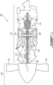
example HEP 100 is shown inFIG. 1 and generally comprises athermal engine 110, anelectric motor 130 and apropeller 120. Thethermal engine 110 is, in this example, a combustion engine, and more particularly a gas turbine engine. Other types of combustion engines, such as turboshaft and turbofan gas turbine engines, and internal combustion engines, may also be used for the thermal engine. Generally, thethermal engine 110 may be any system that converts heat or thermal energy to mechanical energy which can then be used to drive a load, such as thepropeller 120. The load can also be a fan, rotor system, and the like. Theelectric motor 130 may be any type of electric motor, including an electric machine that can be driven as a motor or as a generator. - The
propeller 120 is attached to ashaft 108. In the depicted embodiment, thethermal engine 110 includes, in serial flow communication, acompressor section 114 for pressurizing the air, acombustor 116 in which the compressed air is mixed with fuel and ignited for generating an annular stream of hot combustion gases, and aturbine section 106 for extracting energy from the combustion gases and driving the rotation of the propeller through theshaft 108. Thepropeller 120 converts rotary motion from theshaft 108 of theengine 110 to provide propulsive force for the aircraft, also known as thrust. Thepropeller 120 may be a variable-pitch propeller capable of generating forward and reverse thrust and comprises two ormore propeller blades 122. For a propeller-driven propulsion system, thethermal engine 110 drives thepropeller 120 via a reduction gearbox (RGB) 132. - Also coupled to the
RGB 132 is theelectric motor 130, which uses electricity to provide additional power that is converted to thrust via theRGB 132 towards thepropeller 120. TheHEP 100 thus includes two power sources, namely theelectric motor 130 and thethermal engine 110, whose power is combined through theRGB 132 and used to drive the load (i.e. propeller 120). While thethermal engine 110 and theelectric motor 130 are shown in this example to be coupled to thepropeller 120 through theRGB 132, other configurations are also contemplated. For example, in a pusher-puller configuration, a propulsion unit having a thermal engine and an electric motor may be coupled to one or more loads without a gear box. - Referring to
FIG. 2 , apower management system 200 is coupled to theHEP 100, which includes thethermal engine 110,electric motor 130, and a common gearbox 232 (which can also provide the mechanical speed reduction typically provided by the reduction gearbox 132). Thethermal engine 110 selectively provides a first torque input to theHEP 100, while theelectric motor 130 selectively provides a second torque input to theHEP 100. A power request is received, for example from apower throttle 202 in an aircraft cockpit, at thepower management system 200. Thepower throttle 202 may be an angularly displaceable power lever or a collective lever, and defines a power lever angle (PLA) or throttle lever angle representative of the power request. In some embodiments, the total power request may come from another aircraft or avionic system, or from an engine system or controller. For example, the power request may be sent from thepower throttle 202 to another system which may then provide the information to thepower management system 200. Thepower management system 200 converts the total power request into an electric power request and a thermal power request in accordance with a desired proportion of electric power and thermal power. The electric power request and thermal power requests are then converted into an electric power command and a thermal power command, respectively, which are used to drive theelectric motor 130 andthermal engine 110, respectively. It will be understood that the breakdown between thermal power and electric power may vary anywhere between 0% to 100% for either power source. - In an exemplary embodiment, the initial power demand is satisfied only by the
thermal engine 110. As the power demand exceeds the capacity of thethermal engine 110, the assistance of theelectric motor 130 is used to complement the power output of thethermal engine 110. As the power demand is reduced, the assistance of theelectric motor 130 is reduced as required. - Referring to
FIG. 3 , an embodiment of thepower management system 200 is shown. The depictedpower management system 200 includes an engine control unit (ECU) 210, illustratively a dual channel ECU 210 having afirst channel ECU 1 210a and asecond channel ECU 2 210b. In other embodiments, a single channel ECU 210 may be provided. The ECU 210 receives two inputs from theHEP 100 and aircraft:current torque 220, and a position of thepower throttle 202, also referred to as power lever angle (PLA) 230. The ECU 210 may control operations of thethermal engine 110, for instance by controlling fuel supplied to thethermal engine 110. An electric propulsion controller (EPC) 240 is operatively coupled to a battery management system (BMS) 250 and theelectric motor 130 to control the power supplied to theelectric motor 130 from theBMS 250. In various embodiments, the ECU 210,EPC 240 andBMS 250 can be packaged together in one or more electronic controllers embodying both hardware and software. - The depicted
power management system 200 further includes aprotection module 260 for theEPC 240. Illustratively, theprotection module 260 is a hardware channel of the software-basedEPC 240. Theprotection module 260 is operable to disable theelectric motor 130 based on the position of the power throttle 202 (i.e., the PLA 230), thereby preventing theelectric motor 130 from applying immediate power or thrust under failure conditions, which can lead to undesirable rotor overspeed or overtorque. In various embodiments, the signal may be sent to the protection module upon detection, for instance by the ECU and/or by the pilot, of an overspeed condition and/or an overtorque condition in theHEP 100. A detected overspeed or overtorque condition may be understood as being at or after the onset of an overspeed or overtorque condition of theHEP 100. In an embodiment, theprotection module 260 includes field programmable gate arrays (FPGAs). Various cases of failure may lead to such conditions, as theEPC 240 may send inadvertent signals to theEPC 240 indicating that theelectric motor 130 should apply torque in cases where such torque is not needed. For instance, under low power levels, thepropeller 120 is typically being controlled to a finer than usual blade angle when compared to high power operation. In the low power regime, thepropeller 120 may be subjected to overspeed under failure conditions, given the reduced rotational drag of the blades. TheEPC protection module 260 may therefore prevent this from occurring. Similarly, during aircraft flare maneuvers near the ground, a rapid application of torque on a propeller-driven aircraft may undesirably provide instantaneous lift. Rapid application of asymmetric power during this phase of flight could result in wing tip contact with the ground or a runaway excursion, resulting in a potentially catastrophic accident. TheEPC protection module 260 may therefore prevent this from occurring. - In the shown embodiment, the
power throttle 202 is provided with amicroswitch 204 operable to detect a throttle position of the power throttle 202 (or PLA 230), below which theelectric motor 130 would not be called upon to provide additional thrust or torque to supplement the thrust or torque provided by thethermal engine 110. Stated differently, the predetermined PLA may correspond to aPLA 230 below which theelectric motor 130 is ordinarily, i.e., under normal operating conditions, in an inactive state. Themicroswitch 204 is operatively coupled to theEPC protection module 260 and provides a signal to theEPC protection module 260, that is independent and overriding of the software of any controller (i.e., the ECU 210 or the EPC 240), when the throttle position is at or below the predetermined throttle position. As such, based on the position of the PLA, theEPC protection module 260 can disable or de-activate the supply of electrical power from theBMS 250 to theEPC 240. Thus, in a power regime where theelectric motor 130 is not expected to provide thrust or torque, the EPC protection module is operable to prevent theelectric motor 130 from providing any thrust or torque, regardless of any signals from one or more controllers, stemming from a failure condition, prompting theelectric motor 130 to unexpectedly and/or undesirably do so. In other embodiments, themicroswitch 204 may be replaced with another sensor for detection the position of thepower throttle 202, for instance a rotary variable differential transformer (RVDT) sensor or a Hall sensor. Therefore, below the specific throttle position of thePLA 230 at which the microswitch 204 (or other like sensor) is activated, theelectric motor 130 will not be operational, regardless of any malfunctions that could lead to unintentional activation of theelectric motor 130 that could otherwise lead to overspeed or overtorque conditions. The above-described system may be easily useable by a pilot of an aircraft, as they are trained to pulled back on thepower throttle 202 to reduce power. This familiar action may now allow them to know with certainty that, beyond a certain angular position of thepower throttle 202, theelectric motor 130 will be deactivated through hardware means. In some embodiments, a deactivatedelectrical motor 130 may be reactivated when called upon to crank theHEP 100 to start thethermal engine 110, which may occur with thepower throttle 202 at idle. - Referring to
FIG. 4 , another embodiment of a power management system 200' is shown. In this embodiment, thepower throttle 202 is not provided with a microswitch, and overspeed and overtorque protection is realized through one channel of the ECU 210', illustrativelyECU 2 210b', sending an electric discrete or other like signal to the EPC protection module 260' to prevent theBMS 250' from supplying power to the electric motor 130 (not shown inFIG. 4 ). The other channel of the ECU 210', illustrativelyECU 1 210a', may send a command signal straight to theBMS 250', for instance over CANBUS, to prevent theBMS 250' from supplying power to theelectric motor 130. A channel of the ECU 210', illustrativelyECU 1 210a', may perform constant validity checks to determine if a failure condition is likely to occur, for instance based on one or more detected conditions, and if the disabling of theelectric motor 130 is appropriate. A channel of the ECU 210', illustrativelyECU 1 210a', may be operable to detect an overspeed condition and/or an overtorque condition in theHEP 100 and transmit a command to the protection module 260' in response. In the shown embodiment, the ECU 210' is operable to receive various torque and PLA inputs,illustratively torque 1 220a',torque 2 220b,PLA 1 230a' andPLA 2 230b'. Additionally or alternatively, the ECU 210' may be operable to receive various inputs such asPLA 1 230a',PLA 2 230b',torque 1 220a' andtorque 2 220b', deduce a requested torque, compare the requested torque to an actual torque, and transmit the command to the protection module 260' if the requested and actual torques vary by a predetermined degree. - Referring to
FIG. 5 , there is shown anexemplary method 500 managing a hybrid-electric powerplant (HEP), forinstance HEP 100, comprising athermal engine 110 and anelectric motor 130. - At
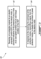
step 502, a command is received, at aprotection module 260 for an electric propulsion control (EPC) 240 for theelectric motor 130, indicative of the presence of one or more of an over-speed condition and an over-torque condition of theHEP 100. In some embodiments, the command is received from a sensor, forinstance microswitch 204, disposed at a predetermined position on apower throttle 202 for theHEP 100. - At
step 504, in response to the receiving the command at theprotection module 260, a signal is transmitted, from theprotection module 260, to disable the provision of power to theelectric motor 130. In some embodiments, the signal is transmitted from theprotection module 260 to a battery management system (BMS) 250 for theelectric motor 130. - In some embodiments, the
method 500 further includes monitoring, an engine control unit (ECU) 210 of theHEP 100, one or more operating conditions of theHEP 100, and, in response to detecting a failure condition, transmitting the command to theprotection module 260 to disable the provision of power to theelectric motor 130. - The power management system 200 (or 200') may be implemented with one or
more computing device 600, an example of which is illustrated inFIG. 6 . For simplicity only onecomputing device 600 is shown but, for example, each controller may be implemented by one or more of thecomputing devices 600. Thecomputing devices 600 may be the same or different types of devices. The various controllers can be implemented as part of a full-authority digital engine controls (FADEC) or other similar device, including electronic engine control (EEC), engine control unit (ECU), electronic propeller control, propeller control unit, and the like. The motor controller can be implemented as part of a motor controller (MC), electric motor controller (EMC), electric powertrain controller (EPC, as described above), and the like. Other embodiments may also apply. - The
computing device 600 comprises aprocessing unit 602 and amemory 604 which has stored therein computer-executable instructions 606. Theprocessing unit 602 may comprise any suitable devices configured to implement themethod 500 such thatinstructions 606, when executed by thecomputing device 600 or other programmable apparatus, may cause the functions/acts/steps performed as part of themethod 500 as described herein to be executed. Theprocessing unit 602 may comprise, for example, any type of general-purpose microprocessor or microcontroller, a digital signal processing (DSP) processor, a central processing unit (CPU), an integrated circuit, a field programmable gate array (FPGA), a reconfigurable processor, other suitably programmed or programmable logic circuits, or any combination thereof. - The
memory 604 may comprise any suitable known or other machine-readable storage medium. Thememory 604 may comprise non-transitory computer readable storage medium, for example, but not limited to, an electronic, magnetic, optical, electromagnetic, infrared, or semiconductor system, apparatus, or device, or any suitable combination of the foregoing. Thememory 604 may include a suitable combination of any type of computer memory that is located either internally or externally to device, for example random-access memory (RAM), read-only memory (ROM), compact disc read-only memory (CDROM), electro-optical memory, magnetooptical memory, erasable programmable read-only memory (EPROM), and electrically-erasable programmable read-only memory (EEPROM), Ferroelectric RAM (FRAM) or the like.Memory 604 may comprise any storage means (e.g., devices) suitable for retrievably storing machine-readable instructions 606 executable by processingunit 602. - The methods and systems for power management of an HEP described herein may be implemented in a high level procedural or object oriented programming or scripting language, or a combination thereof, to communicate with or assist in the operation of a computer system, for example the
computing device 600. Alternatively, the methods and systems for power management may be implemented in assembly or machine language. The language may be a compiled or interpreted language. Program code for implementing the methods and systems for power management may be stored on a storage media or a device, for example a ROM, a magnetic disk, an optical disc, a flash drive, or any other suitable storage media or device. The program code may be readable by a general or special-purpose programmable computer for configuring and operating the computer when the storage media or device is read by the computer to perform the procedures described herein. Embodiments of the methods and systems for power management may also be considered to be implemented by way of a non-transitory computer-readable storage medium having a computer program stored thereon. The computer program may comprise computer-readable instructions which cause a computer, or more specifically theprocessing unit 602 of thecomputing device 600, to operate in a specific and predefined manner to perform the functions described herein, for example those described in themethod 500. - Computer-executable instructions may be in many forms, including program modules, executed by one or more computers or other devices. Generally, program modules include routines, programs, objects, components, data structures, etc., that perform particular tasks or implement particular abstract data types. Typically the functionality of the program modules may be combined or distributed as desired in various embodiments.
- The embodiments described herein are implemented by physical computer hardware, including computing devices, servers, receivers, transmitters, processors, memory, displays, and networks. The embodiments described herein provide useful physical machines and particularly configured computer hardware arrangements. The embodiments described herein are directed to electronic machines and methods implemented by electronic machines adapted for processing and transforming electromagnetic signals which represent various types of information. The embodiments described herein pervasively and integrally relate to machines, and their uses; and the embodiments described herein have no meaning or practical applicability outside their use with computer hardware, machines, and various hardware components. Substituting the physical hardware particularly configured to implement various acts for non-physical hardware, using mental steps for example, may substantially affect the way the embodiments work. Such computer hardware limitations are clearly essential elements of the embodiments described herein, and they cannot be omitted or substituted for mental means without having a material effect on the operation and structure of the embodiments described herein. The computer hardware is essential to implement the various embodiments described herein and is not merely used to perform steps expeditiously and in an efficient manner.
- The term "connected" or "coupled to" may include both direct coupling (in which two elements that are coupled to each other contact each other) and indirect coupling (in which at least one additional element is located between the two elements).
- The technical solution of embodiments may be in the form of a software product. The software product may be stored in a non-volatile or non-transitory storage medium, which can be a compact disk read-only memory (CD-ROM), a USB flash disk, or a removable hard disk. The software product includes a number of instructions that enable a computer device (personal computer, server, or network device) to execute the methods provided by the embodiments.
- The embodiments described in this document provide non-limiting examples of possible implementations of the present technology. Upon review of the present disclosure, a person of ordinary skill in the art will recognize that changes may be made to the embodiments described herein without departing from the scope of the present technology. Yet further modifications could be implemented by a person of ordinary skill in the art in view of the present disclosure, which modifications would be within the scope of the present technology.
Claims (15)
- A hybrid-electric powerplant (HEP) (100) of an aircraft, comprising:a thermal engine (110) providing a first torque input to the HEP (100);an electric motor (130) providing a second torque input to the HEP (100);a power management system (200; 200') connected to one or both of the thermal engine (110) and the electric motor (130), the power management system (200; 200') comprising:an engine control unit (ECU) (210; 210') connected to the thermal engine (110), the ECU (210; 210') controlling fuel supplied to the thermal engine (110); andan electric propulsion control (EPC) (240) connected to the electric motor (130), the EPC (240) controlling power supplied to the electric motor (130), the EPC (240) including an EPC protection module (260; 260') in communication with a power source for the electric motor (130), the EPC protection module (260; 260') disabling power supplied to the electric motor (130) upon receipt of a signal indicative of one or more of an over-speed condition and an over-torque condition detected in the HEP (100).
- The HEP (100) as defined in claim 1, wherein the signal is a pilot-generated command.
- The HEP (100) as defined in claim 2, further comprising a sensor (204) and a power throttle (202), the sensor (204) operable to detect a throttle position of the power throttle (202) of the HEP (100), the sensor (204) operatively connected to the EPC protection module (260) and operable to produce the pilot-generated command when the throttle position is at or below a predetermined throttle position.
- The HEP (100) as defined in claim 3, wherein the power throttle (202) includes a power lever that is angularly displaceable, the sensor (204) operable to detect a power lever angle (PLA) (230) of the power lever.
- The HEP (100) as defined in claim 4, wherein the predetermined throttle position corresponds to a fixed PLA (230) below which the electric motor (130) is ordinarily in an inactive state.
- The HEP (100) as defined in any of the preceding claims, further comprising a battery management system (BMS) (250; 250') for the electric motor (130), the BMS (250; 250') operable to receive the signal from the EPC protection module (260; 260') and disable a provision of power to the electric motor (130).
- The HEP (100) as defined in any of the preceding claims, wherein the ECU (210; 210') is operable to monitor one or more operating conditions of the HEP (100) and, in response to detecting one or more of an over-speed condition and an over-torque condition in the HEP (100), to transmit the signal to the EPC protection module (260; 260').
- A method for managing a hybrid-electric powerplant (HEP) (100) comprising a thermal engine (110) and an electric motor (130), comprising:receiving, at a protection module (260; 260') for an electric propulsion control (EPC) (240) for the electric motor (130), a command indicative of the presence of one or more of an over-speed condition and an over-torque condition of the HEP (100); andin response to the receiving the command at the protection module (260; 260'), transmitting a signal, from the protection module (260; 260'), to disable the provision of power to the electric motor (130).
- The method as defined in claim 8, wherein receiving the command at the protection module (260; 260') includes receiving a pilot-generated command.
- The method as defined in claim 9, wherein receiving the pilot-generated command includes receiving the pilot-generated command from a sensor (204) operable to detect a throttle position of a power throttle (202) for the HEP (100), the sensor (204) operatively connected to the protection module (260) and operable to produce the pilot-generated command when the throttle position is at or below a predetermined throttle position.
- The method as defined in claim 10, wherein the power throttle (202) includes a power lever that is angularly displaceable, the sensor (204) operable to detect a power lever angle (PLA) (230) of the power lever.
- The method as defined in claim 11, wherein the predetermined throttle position corresponds to a fixed PLA (230) below which the electric motor (130) is ordinarily in an inactive state.
- The method as defined in any of claims 8 to 12, wherein transmitting the signal from the protection module (260; 260') to disable the provision of power to the electric motor (130) includes transmitting the signal from the protection module (260; 260') to a battery management system (BMS) (250; 250') for the electric motor (130).
- The method as defined in any of claims 8 to 13, further comprising monitoring, at an engine control unit (ECU) (210; 210') of the HEP (100), one or more operating conditions of the HEP (100), and, in response to detecting one or more of an over-speed condition and an over-torque condition in the HEP (100), transmitting the command to the protection module (260; 260').
- A power management system (200; 200') for a hybrid-electric powerplant (HEP) (100) comprising a thermal engine (110) and an electric motor (130), the power management system (200; 200') comprising at least one controller having at least one processor (602) and a memory (604) coupled thereto, the memory (604) having stored thereon program instructions (606) executable by the at least one processor (602) for:receiving, at a protection module (260; 260') for an electric propulsion control (EPC) (240) for the electric motor (130), a command indicative of the presence of one or more of an over-speed condition and an over-torque condition of the HEP (100); andin response to the receiving the command at the protection module (260; 260'), transmitting a signal, from the protection module (260; 260'), to disable the provision of power to the electric motor (130).
Applications Claiming Priority (1)
| Application Number | Priority Date | Filing Date | Title |
|---|---|---|---|
| US17/937,871 US20240113513A1 (en) | 2022-10-04 | 2022-10-04 | Overspeed and/or overtorque protection for hybrid electric aircraft propulsion system |
Publications (1)
| Publication Number | Publication Date |
|---|---|
| EP4350135A2 true EP4350135A2 (en) | 2024-04-10 |
Family
ID=88241474
Family Applications (1)
| Application Number | Title | Priority Date | Filing Date |
|---|---|---|---|
| EP23201463.9A Pending EP4350135A2 (en) | 2022-10-04 | 2023-10-03 | Overspeed and/or overtorque protection for hybrid electric aircraft propulsion system |
Country Status (3)
| Country | Link |
|---|---|
| US (1) | US20240113513A1 (en) |
| EP (1) | EP4350135A2 (en) |
| CA (1) | CA3210761A1 (en) |
-
2022
- 2022-10-04 US US17/937,871 patent/US20240113513A1/en active Pending
-
2023
- 2023-08-31 CA CA3210761A patent/CA3210761A1/en active Pending
- 2023-10-03 EP EP23201463.9A patent/EP4350135A2/en active Pending
Also Published As
| Publication number | Publication date |
|---|---|
| US20240113513A1 (en) | 2024-04-04 |
| CA3210761A1 (en) | 2024-04-04 |
Similar Documents
| Publication | Publication Date | Title |
|---|---|---|
| US10773814B2 (en) | Control system for rotorcraft in-flight engine restarting | |
| US10040566B2 (en) | Hybrid contingency power drive system | |
| US9387934B2 (en) | Method and a rotary wing aircraft having three engines | |
| US10759280B2 (en) | Hybrid electric power drive system for a rotorcraft | |
| US11597526B2 (en) | Control systems for hybrid electric powerplants | |
| US11299286B2 (en) | System and method for operating a multi-engine aircraft | |
| US11391203B2 (en) | Asymmetric propulsion system with heat recovery | |
| US20200362723A1 (en) | System and method for detecting an uncommanded or uncontrollable high thrust event in an aircraft | |
| US20230203994A1 (en) | System and method for operating a multi-engine aircraft | |
| US20200331621A1 (en) | Method of optimizing the noise generated on the ground by a rotorcraft | |
| EP3670876A1 (en) | System and method for operating a gas turbine engine coupled to an aircraft propeller | |
| US20240092497A1 (en) | Hybrid propulsion system for a helicopter | |
| CN110225863B (en) | Method and system for controlling an emergency device | |
| EP4032812A1 (en) | Methods and systems for power management of a hybrid electric powerplant | |
| EP4350135A2 (en) | Overspeed and/or overtorque protection for hybrid electric aircraft propulsion system | |
| US11719167B2 (en) | Operating a turboprop engine for in-flight restart | |
| US20240132226A1 (en) | Hybrid-electric propulsion system equipped with a coupler for switching between modes of operation | |
| CN114651112A (en) | Method for quickly stopping rotor wing after helicopter landing |
Legal Events
| Date | Code | Title | Description |
|---|---|---|---|
| PUAI | Public reference made under article 153(3) epc to a published international application that has entered the european phase |
Free format text: ORIGINAL CODE: 0009012 |
|
| STAA | Information on the status of an ep patent application or granted ep patent |
Free format text: STATUS: THE APPLICATION HAS BEEN PUBLISHED |
|
| AK | Designated contracting states |
Kind code of ref document: A2 Designated state(s): AL AT BE BG CH CY CZ DE DK EE ES FI FR GB GR HR HU IE IS IT LI LT LU LV MC ME MK MT NL NO PL PT RO RS SE SI SK SM TR |