EP4350070A1 - A household appliance with height adjustable foot - Google Patents
A household appliance with height adjustable foot Download PDFInfo
- Publication number
- EP4350070A1 EP4350070A1 EP23200477.0A EP23200477A EP4350070A1 EP 4350070 A1 EP4350070 A1 EP 4350070A1 EP 23200477 A EP23200477 A EP 23200477A EP 4350070 A1 EP4350070 A1 EP 4350070A1
- Authority
- EP
- European Patent Office
- Prior art keywords
- foot
- household appliance
- counternut
- pressing surface
- protrusion
- Prior art date
- Legal status (The legal status is an assumption and is not a legal conclusion. Google has not performed a legal analysis and makes no representation as to the accuracy of the status listed.)
- Pending
Links
Images





Classifications
-
- D—TEXTILES; PAPER
- D06—TREATMENT OF TEXTILES OR THE LIKE; LAUNDERING; FLEXIBLE MATERIALS NOT OTHERWISE PROVIDED FOR
- D06F—LAUNDERING, DRYING, IRONING, PRESSING OR FOLDING TEXTILE ARTICLES
- D06F39/00—Details of washing machines not specific to a single type of machines covered by groups D06F9/00 - D06F27/00
- D06F39/12—Casings; Tubs
- D06F39/125—Supporting arrangements for the casing, e.g. rollers or legs
Definitions
- the present invention relates to a household appliance comprising height adjustable feet.
- the height of the feet carrying the body are adjusted in order to ensure the balance of the household appliance on the floor whereon the same is installed.
- Height adjustment is performed by means of various mechanisms which make it easier to reach the feet on the household appliance or by manually turning the feet around their own axis. Taking into account the load carried by the feet, height adjustment cannot be performed easily even if various auxiliary mechanisms and hand tools are used to rotate the feet.
- the adjustable foot mechanism especially used in washing machines, keeps the whole body on the floor fixed and carries the same.
- the adjustable foot mechanism comprises a bolt, a rubber damper, a carrier lower part and a counternut, and there are four in the washing machine.
- the rubber damper By means of the rubber damper, it is ensured that the washing machine sits on the floor more securely and does not move. Thus, especially on wet floors such as bathrooms, it is ensured that the washing machine sits on the floor thanks to the load thereof and almost sticks to the floor.
- the counternut also ensures that the foot is fixed on the body with a counter effect against the tightening direction on uneven ground.
- the counternut is octagonal so as to facilitate rotation by hand.
- the rib structures on the side skirts of the counternut provide strength, thus preventing the same from breaking.
- the tightening torque of the adjustable foot mechanism during the production phase is set between 1.2 Nm. And 1.5 Nm.
- the forces applied to the body cause problems such as releasing (loosening) of the preset torque in the adjustable foot mechanisms as a result of the loading/unloading processes of the household appliance.
- a household appliance having a height adjustment mechanism which is disposed between an abutment seated on the floor and a shaft attached to the body and which is connected to the shaft.
- the aim of the present invention is the realization of a household appliance comprising height adjustable feet.
- the household appliance realized in order to attain the aim of the present invention, explicated in the first claim and the respective claims thereof, comprises a body; at least one foot which is attached to the body; a bolt which is disposed perpendicular to and coaxially with the foot; a counternut which is in the form of a ring, which is disposed between the foot and the body and which is fitted over the bolt so as to be parallel to the foot and coaxially with the foot and the bolt; a pressing surface which is provided on the upper or lower surface of the counternut; and one or more than one protrusion which is provided on the pressing surface and which extend from the pressing surface towards the body or the foot.
- the protrusion gets into contact with the base of the body and increases the contact surface area of the pressing surface. Additionally, in another embodiment of the present invention, the protrusion gets into contact with the foot and increases the contact surface area of the pressing surface. Thus, by providing pre-tension, the friction coefficient is increased and the loosening torque is increased to higher values. Thus, the tightening torque set during production is not released.
- the foot comprises a base and a receptacle at the center of the base.
- the bolt head is seated into the receptacle.
- the foot and the bolt are coaxially placed.
- the foot is manufactured from rubber.
- the counternut comprises a bearing wherein the bolt is seated and an abutment which surrounds the bearing and whereon the pressing surface is disposed.
- the counternut further comprises a skirt in the form of a ring which surrounds the abutment and at least one rib which connects the skirt and the abutment to each other. By means of the rib, strength is provided, thus preventing breaking.
- the skirt is octagonal and the ribs are provided on the diagonal lines. By means of the octagonal skirt, the counternut is enabled to be rotated easily by hand.
- the protrusion is inclined at an angle of at least 45° with respect to the pressing surface.
- the protrusion is squeezed between the base of the body and the pressing surface, and after moving away from the body base, the pressing surface returns to the initial position.
- the protrusion almost serves as a spring.
- the household appliance comprises four protrusions.
- the protrusion is hemispherical.
- the household appliance comprises eight protrusions.
- the protrusion is in the form of a quadrangular prism.
- the household appliance comprises twelve protrusions.
- the protrusion is semicylindrical.
- the household appliance comprises eighteen protrusions.
- the contact surface area is increased thanks to contact to the base of the body by means of the protrusions and the friction coefficient is increased by providing pre-tension.
- the loosening torque is increased to higher values.
- the protrusions create friction on the surface area whereon the same press, thus creating a positive effect against loosening.
- the household appliance comprises a body (1); at least one foot (2) which is attached to the body (1); a bolt (5) which is disposed perpendicular to and coaxially with the foot (2); a counternut (7) which is in the form of a ring, which is disposed between the foot (2) and the body (1) and which is fitted over the bolt (5) so as to be parallel to the foot (2) and coaxially with the foot (2) and the bolt (5); a pressing surface (10) which is provided on the upper and lower surface of the counternut (7); and one or more than one protrusion (11) which is provided on at least one pressing surface (10) and which extend from the pressing surface (10) towards at least one of at least two ends of the bolt.
- the protrusion (11) extends on the counternut (7) between the pressing surface (10) and the base of the body (1).
- the protrusion (11) gets into contact with the base of the body (1) and increases the contact surface area of the pressing surface.
- the protrusion (11) extends on the pressing surface (10) under the counternut(7) between the pressing surface (10) and the foot (2).
- the protrusion (11) also gets into contact with the foot (2) and increases the contact surface area of the pressing surface (10) provided at the top and bottom.
- the bolt (5) is mounted coaxially with the foot (2) and perpendicular to the foot (2) such that the bolt head (6) is fitted into the receptacle (4). Then, the bolt (5) is borne on the counternut (7) by means of the bearing (8) and is attached to the body (1).
- the same is grasped by means of the skirt (12) on the counternut (7) and the bolt (5) is rotated around its own axis.
- the counternut (7) approaches the body (1) and the protrusions (11) touch the base of the body (1) and are compressed between the base of the body (1) and the pressing surface (10) by rotating the counternut (7).
- the counternut (7) when rotated in the opposite direction, the counternut (7) this time approaches the foot (2) and the protrusions (11) touch the ceiling of the foot (2) and are compressed between the ceiling of the foot (2) and the pressing surface (10) by rotating the counternut (7).
- the protrusions (11) By means of the protrusions (11), the friction surface area is increased, thus preventing the counternut (7) from loosening easily and enabling the same to maintain the set torque value for a longer period of time.
- the foot (2) comprises a base (3) and a receptacle (4) at the center of the base (3).
- the bolt head (6) is seated into the receptacle (4).
- the foot (2) and the bolt (5) are coaxially placed.
- the foot (2) is manufactured from rubber.
- the counternut (7) comprises a bearing (8) wherein the bolt (5) is seated and an abutment (9) which surrounds the bearing (8) and whereon the pressing surface (10) is disposed.
- the counternut (7) further comprises a skirt (12) in the form of a ring which surrounds the abutment (9) and at least one rib (13) which connects the skirt (12) and the abutment (9) to each other.
- the skirt (12) is octagonal and the ribs (13) are provided on the diagonal lines.
- the protrusion (11) is inclined at an angle of at least 45° with respect to the pressing surface (10).
- the protrusion (11) is squeezed between the base of the body (1) and the pressing surface (10), and after moving away from the body (1) base, the pressing surface (10) returns to the initial position.
- the protrusion (11) almost serves as a spring.
- the household appliance (1) comprises four protrusions (11) ( Figure 5, Figure 6 , Figure 7 and Figure 8 ).
- the protrusion (11) is hemispherical.
- the household appliance (1) comprises eight protrusions (11) ( Figure 9, Figure 10 , Figure 11 and Figure 12 ).
- the protrusion (11) is in the form of a quadrangular prism.
- the household appliance (1) comprises twelve protrusions (11) ( Figure 13, Figure 14 , Figure 15 and Figure 16 ).
- the protrusion (11) is semicylindrical.
- the household appliance (1) comprises eighteen protrusions (11) ( Figure 17, Figure 18 , Figure 19 and Figure 20 ).
- the household appliance is a laundry washer/dryer or a washing machine.
- the contact surface area is increased thanks to contact to the base of the body (1) by means of the protrusions (11) and the friction coefficient is increased by providing pre-tension.
- the loosening torque is increased to higher values.
- the protrusions (11) create friction on the surface area whereon the same press, thus creating a positive effect against loosening.
Landscapes
- Engineering & Computer Science (AREA)
- Textile Engineering (AREA)
- Food-Manufacturing Devices (AREA)
Abstract
The present invention relates to a household appliance comprising a body (1); at least one foot (2) which is attached to the body (1); a bolt (5) which is disposed perpendicular to and coaxially with the foot (2); and a counternut (7) which is in the form of a ring, which is disposed between the foot (2) and the body (1) and which is fitted over the bolt (5) so as to be parallel to the foot (2) and coaxially with the foot (2) and the bolt (5).
Description
- The present invention relates to a household appliance comprising height adjustable feet.
- In household appliances such as washing machines, laundry dryers, dishwashers, ovens, cooling devices, and freezers, the height of the feet carrying the body are adjusted in order to ensure the balance of the household appliance on the floor whereon the same is installed. Height adjustment is performed by means of various mechanisms which make it easier to reach the feet on the household appliance or by manually turning the feet around their own axis. Taking into account the load carried by the feet, height adjustment cannot be performed easily even if various auxiliary mechanisms and hand tools are used to rotate the feet.
- The adjustable foot mechanism, especially used in washing machines, keeps the whole body on the floor fixed and carries the same.
- In the state of the art, the adjustable foot mechanism comprises a bolt, a rubber damper, a carrier lower part and a counternut, and there are four in the washing machine. By means of the rubber damper, it is ensured that the washing machine sits on the floor more securely and does not move. Thus, especially on wet floors such as bathrooms, it is ensured that the washing machine sits on the floor thanks to the load thereof and almost sticks to the floor. The counternut also ensures that the foot is fixed on the body with a counter effect against the tightening direction on uneven ground. The counternut is octagonal so as to facilitate rotation by hand. The rib structures on the side skirts of the counternut provide strength, thus preventing the same from breaking. The tightening torque of the adjustable foot mechanism during the production phase is set between 1.2 Nm. And 1.5 Nm. However, the forces applied to the body cause problems such as releasing (loosening) of the preset torque in the adjustable foot mechanisms as a result of the loading/unloading processes of the household appliance.
- In the state of the art European Patent Application No.
EP0874186 , a household appliance is disclosed, having a height adjustment mechanism which is disposed between an abutment seated on the floor and a shaft attached to the body and which is connected to the shaft. - The aim of the present invention is the realization of a household appliance comprising height adjustable feet.
- The household appliance realized in order to attain the aim of the present invention, explicated in the first claim and the respective claims thereof, comprises a body; at least one foot which is attached to the body; a bolt which is disposed perpendicular to and coaxially with the foot; a counternut which is in the form of a ring, which is disposed between the foot and the body and which is fitted over the bolt so as to be parallel to the foot and coaxially with the foot and the bolt; a pressing surface which is provided on the upper or lower surface of the counternut; and one or more than one protrusion which is provided on the pressing surface and which extend from the pressing surface towards the body or the foot.
- In the preferred embodiment of the present invention, the protrusion gets into contact with the base of the body and increases the contact surface area of the pressing surface. Additionally, in another embodiment of the present invention, the protrusion gets into contact with the foot and increases the contact surface area of the pressing surface. Thus, by providing pre-tension, the friction coefficient is increased and the loosening torque is increased to higher values. Thus, the tightening torque set during production is not released.
- The foot comprises a base and a receptacle at the center of the base. The bolt head is seated into the receptacle. The foot and the bolt are coaxially placed. In the preferred embodiment of the present invention, the foot is manufactured from rubber.
- The counternut comprises a bearing wherein the bolt is seated and an abutment which surrounds the bearing and whereon the pressing surface is disposed. The counternut further comprises a skirt in the form of a ring which surrounds the abutment and at least one rib which connects the skirt and the abutment to each other. By means of the rib, strength is provided, thus preventing breaking. In the preferred embodiment of the present invention, the skirt is octagonal and the ribs are provided on the diagonal lines. By means of the octagonal skirt, the counternut is enabled to be rotated easily by hand.
- In an embodiment of the present invention, the protrusion is inclined at an angle of at least 45° with respect to the pressing surface. The protrusion is squeezed between the base of the body and the pressing surface, and after moving away from the body base, the pressing surface returns to the initial position. The protrusion almost serves as a spring. There are at least two protrusions. In the preferred embodiment of the present invention, the household appliance comprises four protrusions.
- In another embodiment of the present invention, the protrusion is hemispherical. In this embodiment, the household appliance comprises eight protrusions.
- In another embodiment of the present invention, the protrusion is in the form of a quadrangular prism. In this embodiment, the household appliance comprises twelve protrusions.
- In another embodiment of the present invention, the protrusion is semicylindrical. In this embodiment, the household appliance comprises eighteen protrusions.
- By means of the present invention, the contact surface area is increased thanks to contact to the base of the body by means of the protrusions and the friction coefficient is increased by providing pre-tension. Thus, the loosening torque is increased to higher values. The protrusions create friction on the surface area whereon the same press, thus creating a positive effect against loosening.
- A household appliance realized in order to attain the aim of the present invention is illustrated in the attached figures, where:
-
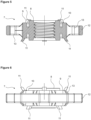
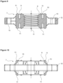
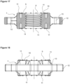
Figure 1 - is the cross-sectional view of a body, a foot, a bolt and a counternut. -
Figure 2 - is the sideways view of the body, the foot, the bolt and the counternut. -
Figure 3 - is the perspective view of the body, the foot, the bolt and the counternut. -
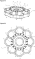
Figure 4 - is the top view of the body, the foot, the bolt and the counternut. -
Figure 5 - is the cross-sectional view of the counternut. -
Figure 6 - is the sideways view of the counternut. -
Figure 7 - is the perspective view of the counternut. -
Figure 8 - is the top view of the counternut. -
Figure 9 - is the cross-sectional view of another embodiment of the counternut. -
Figure 10 - is the sideways view of another embodiment of the counternut. -
Figure 11 - is the perspective view of another embodiment of the counternut. -
Figure 12 - is the top view of another embodiment of the counternut. -
Figure 13 - is the cross-sectional view of yet another embodiment of the counternut. -
Figure 14 - is the sideways view of yet another embodiment of the counternut. -
Figure 15 - is the perspective view of yet another embodiment of the counternut. -
Figure 16 - is the top view of yet another embodiment of the counternut. -
Figure 17 - is the cross-sectional view of another embodiment of the counternut. -
Figure 18 - is the sideways view of another embodiment of the counternut. -
Figure 19 - is the perspective view of another embodiment of the counternut. -
Figure 20 - is the top view of another embodiment of the counternut. - The elements illustrated in the figures are numbered as follows:
- 1.
- Body
- 2.
- Foot
- 3.
- Base
- 4.
- Receptacle
- 5.
- Bolt
- 6.
- Bolt head
- 7.
- Counternut
- 8.
- Bearing
- 9.
- Abutment
- 10.
- Pressing surface
- 11.
- Protrusion
- 12.
- Skirt
- 13.
- Rib
- The household appliance comprises a body (1); at least one foot (2) which is attached to the body (1); a bolt (5) which is disposed perpendicular to and coaxially with the foot (2); a counternut (7) which is in the form of a ring, which is disposed between the foot (2) and the body (1) and which is fitted over the bolt (5) so as to be parallel to the foot (2) and coaxially with the foot (2) and the bolt (5); a pressing surface (10) which is provided on the upper and lower surface of the counternut (7); and one or more than one protrusion (11) which is provided on at least one pressing surface (10) and which extend from the pressing surface (10) towards at least one of at least two ends of the bolt.
- In the preferred embodiment of the present invention, the protrusion (11) extends on the counternut (7) between the pressing surface (10) and the base of the body (1). The protrusion (11) gets into contact with the base of the body (1) and increases the contact surface area of the pressing surface. Additionally, in another embodiment of the present invention, the protrusion (11) extends on the pressing surface (10) under the counternut(7) between the pressing surface (10) and the foot (2). In this embodiment, the protrusion (11) also gets into contact with the foot (2) and increases the contact surface area of the pressing surface (10) provided at the top and bottom. Thus, by providing pre-tension, the friction coefficient is increased and the loosening torque is increased to higher values. Thus, the tightening torque set during production is not released (
Figure 1, Figure 2 ,Figure 3 and Figure 4 ). - In the embodiment of the present invention, the bolt (5) is mounted coaxially with the foot (2) and perpendicular to the foot (2) such that the bolt head (6) is fitted into the receptacle (4). Then, the bolt (5) is borne on the counternut (7) by means of the bearing (8) and is attached to the body (1). When the height of the foot (2) is desired to be adjusted, the same is grasped by means of the skirt (12) on the counternut (7) and the bolt (5) is rotated around its own axis. In this case, the counternut (7) approaches the body (1) and the protrusions (11) touch the base of the body (1) and are compressed between the base of the body (1) and the pressing surface (10) by rotating the counternut (7). Likewise, when rotated in the opposite direction, the counternut (7) this time approaches the foot (2) and the protrusions (11) touch the ceiling of the foot (2) and are compressed between the ceiling of the foot (2) and the pressing surface (10) by rotating the counternut (7). By means of the protrusions (11), the friction surface area is increased, thus preventing the counternut (7) from loosening easily and enabling the same to maintain the set torque value for a longer period of time.
- The foot (2) comprises a base (3) and a receptacle (4) at the center of the base (3). The bolt head (6) is seated into the receptacle (4). The foot (2) and the bolt (5) are coaxially placed. In the preferred embodiment of the present invention, the foot (2) is manufactured from rubber.
- The counternut (7) comprises a bearing (8) wherein the bolt (5) is seated and an abutment (9) which surrounds the bearing (8) and whereon the pressing surface (10) is disposed. The counternut (7) further comprises a skirt (12) in the form of a ring which surrounds the abutment (9) and at least one rib (13) which connects the skirt (12) and the abutment (9) to each other. By means of the rib (13), strength is provided, thus preventing breaking. In the preferred embodiment of the present invention, the skirt (12) is octagonal and the ribs (13) are provided on the diagonal lines. By means of the octagonal skirt (12), the counternut (7) is enabled to be rotated easily by hand.
- In an embodiment of the present invention, the protrusion (11) is inclined at an angle of at least 45° with respect to the pressing surface (10). The protrusion (11) is squeezed between the base of the body (1) and the pressing surface (10), and after moving away from the body (1) base, the pressing surface (10) returns to the initial position. The protrusion (11) almost serves as a spring. In the preferred embodiment of the present invention, the household appliance (1) comprises four protrusions (11) (
Figure 5, Figure 6 ,Figure 7 and Figure 8 ). - In another embodiment of the present invention, the protrusion (11) is hemispherical. In this embodiment of the present invention, the household appliance (1) comprises eight protrusions (11) (
Figure 9, Figure 10 ,Figure 11 and Figure 12 ). - In another embodiment of the present invention, the protrusion (11) is in the form of a quadrangular prism. In this embodiment of the present invention, the household appliance (1) comprises twelve protrusions (11) (
Figure 13, Figure 14 ,Figure 15 and Figure 16 ). - In another embodiment of the present invention, the protrusion (11) is semicylindrical. In this embodiment of the present invention, the household appliance (1) comprises eighteen protrusions (11) (
Figure 17, Figure 18 ,Figure 19 and Figure 20 ). - In the preferred embodiment of the present invention, the household appliance is a laundry washer/dryer or a washing machine.
- By means of the present invention, the contact surface area is increased thanks to contact to the base of the body (1) by means of the protrusions (11) and the friction coefficient is increased by providing pre-tension. Thus, the loosening torque is increased to higher values. The protrusions (11) create friction on the surface area whereon the same press, thus creating a positive effect against loosening.
Claims (13)
- A household appliance comprising a body (1); at least one foot (2) which is attached to the body (1); a bolt (5) which is disposed perpendicular to and coaxially with the foot (2); and a counternut (7) which is in the form of a ring, which is disposed between the foot (2) and the body (1) and which is fitted over the bolt (5) so as to be parallel to the foot (2) and coaxially with the foot (2) and the bolt (5); characterized by a pressing surface (10) which is provided on the upper and lower surface of the counternut (7); and one or more than one protrusion (11) which is provided on at least one pressing surface (10) and which extend from the pressing surface (10) towards at least one of at least two ends of the bolt.
- A household appliance as in Claim 1, characterized by the protrusion (11) which extends on the counternut (7) between the pressing surface (10) and the base of the body (1).
- A household appliance as in Claim 1 or Claim 2, characterized by the protrusion (11) which extends on the pressing surface (10) under the counternut (7) between the pressing surface (10) and the foot (2).
- A household appliance as in any one of the above claims, characterized by the foot (2) which comprises a base (3) and a receptacle (4) at the center of the base (3).
- A household appliance as in any one of the above claims, characterized by the counternut (7) comprising a bearing (8) wherein the bolt (5) is seated, an abutment (9) which surrounds the bearing (8) and whereon the pressing surface (10) is disposed, a skirt (12) in the form of a ring which surrounds the abutment (9) and at least one rib (13) which connects the skirt (12) and the abutment (9) to each other.
- A household appliance as in any one of the above claims, characterized by which the protrusion (11) is inclined at an angle of at least 45° with respect to the pressing surface (10).
- A household appliance as in Claim 6, characterized by the four protrusions (11).
- A household appliance as in any one of Claims 1 to 5, characterized by the protrusion (11) which is hemispherical.
- A household appliance as in Claim 8, characterized by the eight protrusions (11).
- A household appliance as in any one of Claims 1 to 5, characterized by the protrusion (11) which is quadrangular prism.
- A household appliance as in Claim 10, characterized by the twelve protrusions (11).
- A household appliance as in any one of Claims 1 to 5, characterized by the protrusion (11) which is semicylindrical.
- A household appliance as in Claim 12, characterized by the eighteen protrusions (11).
Applications Claiming Priority (1)
| Application Number | Priority Date | Filing Date | Title |
|---|---|---|---|
| TR202215362 | 2022-10-07 |
Publications (1)
| Publication Number | Publication Date |
|---|---|
| EP4350070A1 true EP4350070A1 (en) | 2024-04-10 |
Family
ID=88236638
Family Applications (1)
| Application Number | Title | Priority Date | Filing Date |
|---|---|---|---|
| EP23200477.0A Pending EP4350070A1 (en) | 2022-10-07 | 2023-09-28 | A household appliance with height adjustable foot |
Country Status (1)
| Country | Link |
|---|---|
| EP (1) | EP4350070A1 (en) |
Citations (5)
| Publication number | Priority date | Publication date | Assignee | Title |
|---|---|---|---|---|
| EP0874186A1 (en) | 1997-04-23 | 1998-10-28 | FISHER & PAYKEL LIMITED | Height adjustment or levelling apparatus |
| US20130313385A1 (en) * | 2012-05-22 | 2013-11-28 | General Electric Company | Leveling assembly for an appliance |
| WO2014122886A1 (en) * | 2013-02-08 | 2014-08-14 | パナソニック株式会社 | Adjustable leg for machine |
| CN106480636A (en) * | 2016-10-28 | 2017-03-08 | 无锡小天鹅股份有限公司 | Device for clothing processing |
| CN109972359A (en) * | 2017-12-27 | 2019-07-05 | 青岛海尔滚筒洗衣机有限公司 | A self-locking foot and washing machine |
-
2023
- 2023-09-28 EP EP23200477.0A patent/EP4350070A1/en active Pending
Patent Citations (5)
| Publication number | Priority date | Publication date | Assignee | Title |
|---|---|---|---|---|
| EP0874186A1 (en) | 1997-04-23 | 1998-10-28 | FISHER & PAYKEL LIMITED | Height adjustment or levelling apparatus |
| US20130313385A1 (en) * | 2012-05-22 | 2013-11-28 | General Electric Company | Leveling assembly for an appliance |
| WO2014122886A1 (en) * | 2013-02-08 | 2014-08-14 | パナソニック株式会社 | Adjustable leg for machine |
| CN106480636A (en) * | 2016-10-28 | 2017-03-08 | 无锡小天鹅股份有限公司 | Device for clothing processing |
| CN109972359A (en) * | 2017-12-27 | 2019-07-05 | 青岛海尔滚筒洗衣机有限公司 | A self-locking foot and washing machine |
Similar Documents
| Publication | Publication Date | Title |
|---|---|---|
| US8205843B2 (en) | Rollerball leveling leg | |
| US5944037A (en) | Water spray apparatus for tableware washing machine | |
| US5971350A (en) | Height adjustment or levelling apparatus | |
| EP1530925B1 (en) | Height adjusting apparatus and household electric appliance provided with the same | |
| KR20010015260A (en) | Apparatus and method for rolling clothes in an automatic washer | |
| EP0810317A1 (en) | Washing machine | |
| CA2170676A1 (en) | Appliance mounting assembly | |
| EP1035245B1 (en) | Drive system for a vertical axis washer | |
| US5988574A (en) | Furniture glide | |
| WO2008119475A1 (en) | Improvement in a clothes drying machine and related clothes drying method | |
| CN107120504B (en) | A composite foot device and household appliance | |
| US8528369B2 (en) | Geometric configuration of tub | |
| CN110258077A (en) | A kind of inner cylinder for drum washing machine, roller washing machine and washing methods | |
| US2802356A (en) | Acceleration control device for centrifugal extractors | |
| US8262038B1 (en) | Adjustable machine stabilizer with foot control rotor | |
| CA2095900A1 (en) | Washing machine | |
| US1753722A (en) | Support for centrifugals | |
| EP1156728A1 (en) | Foot for the cabinet of electrical household appliances and other furniture articles | |
| KR101008620B1 (en) | Leg assembly for home appliances | |
| US20050257579A1 (en) | Force isolating applicance | |
| US2641425A (en) | Support | |
| CN108195147A (en) | A kind of weaving drying equipment | |
| KR101033561B1 (en) | Leg assembly for home appliances | |
| JPH077902Y2 (en) | Washing machine leg device | |
| KR200266937Y1 (en) | A rolling equipment which is also served supporting adhered to utensils and furniture |
Legal Events
| Date | Code | Title | Description |
|---|---|---|---|
| PUAI | Public reference made under article 153(3) epc to a published international application that has entered the european phase |
Free format text: ORIGINAL CODE: 0009012 |
|
| STAA | Information on the status of an ep patent application or granted ep patent |
Free format text: STATUS: REQUEST FOR EXAMINATION WAS MADE |
|
| 17P | Request for examination filed |
Effective date: 20230928 |
|
| AK | Designated contracting states |
Kind code of ref document: A1 Designated state(s): AL AT BE BG CH CY CZ DE DK EE ES FI FR GB GR HR HU IE IS IT LI LT LU LV MC ME MK MT NL NO PL PT RO RS SE SI SK SM TR |
|
| STAA | Information on the status of an ep patent application or granted ep patent |
Free format text: STATUS: EXAMINATION IS IN PROGRESS |
|
| 17Q | First examination report despatched |
Effective date: 20260205 |