EP4350046A2 - Electrode, membrane electrode assembly, electrochemical cell, stack, and electrolyzer - Google Patents
Electrode, membrane electrode assembly, electrochemical cell, stack, and electrolyzer Download PDFInfo
- Publication number
- EP4350046A2 EP4350046A2 EP23195663.2A EP23195663A EP4350046A2 EP 4350046 A2 EP4350046 A2 EP 4350046A2 EP 23195663 A EP23195663 A EP 23195663A EP 4350046 A2 EP4350046 A2 EP 4350046A2
- Authority
- EP
- European Patent Office
- Prior art keywords
- catalyst layer
- electrode
- layer
- cracks
- support
- Prior art date
- Legal status (The legal status is an assumption and is not a legal conclusion. Google has not performed a legal analysis and makes no representation as to the accuracy of the status listed.)
- Pending
Links
- 239000012528 membrane Substances 0.000 title claims description 52
- 239000003054 catalyst Substances 0.000 claims abstract description 125
- 239000000835 fiber Substances 0.000 claims description 47
- 239000003792 electrolyte Substances 0.000 claims description 36
- 239000010410 layer Substances 0.000 description 151
- 229910000510 noble metal Inorganic materials 0.000 description 36
- 230000000052 comparative effect Effects 0.000 description 34
- 238000010438 heat treatment Methods 0.000 description 29
- XLYOFNOQVPJJNP-UHFFFAOYSA-N water Substances O XLYOFNOQVPJJNP-UHFFFAOYSA-N 0.000 description 27
- UFHFLCQGNIYNRP-UHFFFAOYSA-N Hydrogen Chemical compound [H][H] UFHFLCQGNIYNRP-UHFFFAOYSA-N 0.000 description 25
- 239000001257 hydrogen Substances 0.000 description 25
- 229910052739 hydrogen Inorganic materials 0.000 description 25
- 229910052751 metal Inorganic materials 0.000 description 23
- QGZKDVFQNNGYKY-UHFFFAOYSA-N Ammonia Chemical compound N QGZKDVFQNNGYKY-UHFFFAOYSA-N 0.000 description 22
- 238000010586 diagram Methods 0.000 description 21
- 239000002184 metal Substances 0.000 description 21
- 238000005868 electrolysis reaction Methods 0.000 description 19
- 239000002245 particle Substances 0.000 description 17
- 239000002923 metal particle Substances 0.000 description 15
- 239000010936 titanium Substances 0.000 description 14
- 229910021529 ammonia Inorganic materials 0.000 description 11
- 229910052741 iridium Inorganic materials 0.000 description 9
- BASFCYQUMIYNBI-UHFFFAOYSA-N platinum Chemical compound [Pt] BASFCYQUMIYNBI-UHFFFAOYSA-N 0.000 description 9
- 239000010955 niobium Substances 0.000 description 8
- 239000002243 precursor Substances 0.000 description 8
- OKTJSMMVPCPJKN-UHFFFAOYSA-N Carbon Chemical compound [C] OKTJSMMVPCPJKN-UHFFFAOYSA-N 0.000 description 7
- QVGXLLKOCUKJST-UHFFFAOYSA-N atomic oxygen Chemical compound [O] QVGXLLKOCUKJST-UHFFFAOYSA-N 0.000 description 7
- 229910052799 carbon Inorganic materials 0.000 description 7
- 239000000463 material Substances 0.000 description 7
- 239000001301 oxygen Substances 0.000 description 7
- 229910052760 oxygen Inorganic materials 0.000 description 7
- RTAQQCXQSZGOHL-UHFFFAOYSA-N Titanium Chemical compound [Ti] RTAQQCXQSZGOHL-UHFFFAOYSA-N 0.000 description 6
- 229910052782 aluminium Inorganic materials 0.000 description 6
- 238000001095 inductively coupled plasma mass spectrometry Methods 0.000 description 6
- 150000004706 metal oxides Chemical class 0.000 description 6
- 238000002156 mixing Methods 0.000 description 6
- 229910052707 ruthenium Inorganic materials 0.000 description 6
- 238000001878 scanning electron micrograph Methods 0.000 description 6
- 229910052719 titanium Inorganic materials 0.000 description 6
- 238000003776 cleavage reaction Methods 0.000 description 5
- 150000002739 metals Chemical class 0.000 description 5
- 229910052697 platinum Inorganic materials 0.000 description 5
- 230000007017 scission Effects 0.000 description 5
- IJGRMHOSHXDMSA-UHFFFAOYSA-N Atomic nitrogen Chemical compound N#N IJGRMHOSHXDMSA-UHFFFAOYSA-N 0.000 description 4
- CURLTUGMZLYLDI-UHFFFAOYSA-N Carbon dioxide Chemical compound O=C=O CURLTUGMZLYLDI-UHFFFAOYSA-N 0.000 description 4
- XAGFODPZIPBFFR-UHFFFAOYSA-N aluminium Chemical compound [Al] XAGFODPZIPBFFR-UHFFFAOYSA-N 0.000 description 4
- 229910052787 antimony Inorganic materials 0.000 description 4
- WATWJIUSRGPENY-UHFFFAOYSA-N antimony atom Chemical compound [Sb] WATWJIUSRGPENY-UHFFFAOYSA-N 0.000 description 4
- 229910052797 bismuth Inorganic materials 0.000 description 4
- JCXGWMGPZLAOME-UHFFFAOYSA-N bismuth atom Chemical compound [Bi] JCXGWMGPZLAOME-UHFFFAOYSA-N 0.000 description 4
- 239000011247 coating layer Substances 0.000 description 4
- 230000007547 defect Effects 0.000 description 4
- 229910052735 hafnium Inorganic materials 0.000 description 4
- VBJZVLUMGGDVMO-UHFFFAOYSA-N hafnium atom Chemical compound [Hf] VBJZVLUMGGDVMO-UHFFFAOYSA-N 0.000 description 4
- 239000007788 liquid Substances 0.000 description 4
- 238000000034 method Methods 0.000 description 4
- 229910052758 niobium Inorganic materials 0.000 description 4
- GUCVJGMIXFAOAE-UHFFFAOYSA-N niobium atom Chemical compound [Nb] GUCVJGMIXFAOAE-UHFFFAOYSA-N 0.000 description 4
- 229910052763 palladium Inorganic materials 0.000 description 4
- 229910052703 rhodium Inorganic materials 0.000 description 4
- VSZWPYCFIRKVQL-UHFFFAOYSA-N selanylidenegallium;selenium Chemical compound [Se].[Se]=[Ga].[Se]=[Ga] VSZWPYCFIRKVQL-UHFFFAOYSA-N 0.000 description 4
- 238000004544 sputter deposition Methods 0.000 description 4
- 229910052715 tantalum Inorganic materials 0.000 description 4
- GUVRBAGPIYLISA-UHFFFAOYSA-N tantalum atom Chemical compound [Ta] GUVRBAGPIYLISA-UHFFFAOYSA-N 0.000 description 4
- JBQYATWDVHIOAR-UHFFFAOYSA-N tellanylidenegermanium Chemical compound [Te]=[Ge] JBQYATWDVHIOAR-UHFFFAOYSA-N 0.000 description 4
- WFKWXMTUELFFGS-UHFFFAOYSA-N tungsten Chemical compound [W] WFKWXMTUELFFGS-UHFFFAOYSA-N 0.000 description 4
- 229910052721 tungsten Inorganic materials 0.000 description 4
- 239000010937 tungsten Substances 0.000 description 4
- OKKJLVBELUTLKV-UHFFFAOYSA-N Methanol Chemical compound OC OKKJLVBELUTLKV-UHFFFAOYSA-N 0.000 description 3
- 238000010306 acid treatment Methods 0.000 description 3
- 238000004458 analytical method Methods 0.000 description 3
- 238000006243 chemical reaction Methods 0.000 description 3
- 238000002484 cyclic voltammetry Methods 0.000 description 3
- 229920002313 fluoropolymer Polymers 0.000 description 3
- 239000000446 fuel Substances 0.000 description 3
- 239000007789 gas Substances 0.000 description 3
- 229910052748 manganese Inorganic materials 0.000 description 3
- 238000004519 manufacturing process Methods 0.000 description 3
- 229910052702 rhenium Inorganic materials 0.000 description 3
- 125000000542 sulfonic acid group Chemical group 0.000 description 3
- UGFAIRIUMAVXCW-UHFFFAOYSA-N Carbon monoxide Chemical compound [O+]#[C-] UGFAIRIUMAVXCW-UHFFFAOYSA-N 0.000 description 2
- 229920000557 Nafion® Polymers 0.000 description 2
- QAOWNCQODCNURD-UHFFFAOYSA-N Sulfuric acid Chemical compound OS(O)(=O)=O QAOWNCQODCNURD-UHFFFAOYSA-N 0.000 description 2
- 239000000956 alloy Substances 0.000 description 2
- 229910002092 carbon dioxide Inorganic materials 0.000 description 2
- 239000001569 carbon dioxide Substances 0.000 description 2
- 229910002091 carbon monoxide Inorganic materials 0.000 description 2
- 229910052802 copper Inorganic materials 0.000 description 2
- 238000000354 decomposition reaction Methods 0.000 description 2
- 230000005611 electricity Effects 0.000 description 2
- 239000004744 fabric Substances 0.000 description 2
- 239000012530 fluid Substances 0.000 description 2
- 238000007731 hot pressing Methods 0.000 description 2
- GKOZUEZYRPOHIO-UHFFFAOYSA-N iridium atom Chemical compound [Ir] GKOZUEZYRPOHIO-UHFFFAOYSA-N 0.000 description 2
- 229910052742 iron Inorganic materials 0.000 description 2
- 239000000203 mixture Substances 0.000 description 2
- 239000002105 nanoparticle Substances 0.000 description 2
- 229910052759 nickel Inorganic materials 0.000 description 2
- 229910052757 nitrogen Inorganic materials 0.000 description 2
- 229920000642 polymer Polymers 0.000 description 2
- 238000003825 pressing Methods 0.000 description 2
- 238000000746 purification Methods 0.000 description 2
- 230000009257 reactivity Effects 0.000 description 2
- 239000000758 substrate Substances 0.000 description 2
- 230000002194 synthesizing effect Effects 0.000 description 2
- 229910021642 ultra pure water Inorganic materials 0.000 description 2
- 239000012498 ultrapure water Substances 0.000 description 2
- 229910052725 zinc Inorganic materials 0.000 description 2
- 239000011701 zinc Substances 0.000 description 2
- JVKRKMWZYMKVTQ-UHFFFAOYSA-N 2-[4-[2-(2,3-dihydro-1H-inden-2-ylamino)pyrimidin-5-yl]pyrazol-1-yl]-N-(2-oxo-3H-1,3-benzoxazol-6-yl)acetamide Chemical compound C1C(CC2=CC=CC=C12)NC1=NC=C(C=N1)C=1C=NN(C=1)CC(=O)NC1=CC2=C(NC(O2)=O)C=C1 JVKRKMWZYMKVTQ-UHFFFAOYSA-N 0.000 description 1
- 229920003934 Aciplex® Polymers 0.000 description 1
- 229920003937 Aquivion® Polymers 0.000 description 1
- MYMOFIZGZYHOMD-UHFFFAOYSA-N Dioxygen Chemical compound O=O MYMOFIZGZYHOMD-UHFFFAOYSA-N 0.000 description 1
- VGGSQFUCUMXWEO-UHFFFAOYSA-N Ethene Chemical compound C=C VGGSQFUCUMXWEO-UHFFFAOYSA-N 0.000 description 1
- 239000005977 Ethylene Substances 0.000 description 1
- 229920003935 Flemion® Polymers 0.000 description 1
- 239000002253 acid Substances 0.000 description 1
- 229910045601 alloy Inorganic materials 0.000 description 1
- 229910002064 alloy oxide Inorganic materials 0.000 description 1
- 150000004945 aromatic hydrocarbons Chemical class 0.000 description 1
- JHRWWRDRBPCWTF-OLQVQODUSA-N captafol Chemical group C1C=CC[C@H]2C(=O)N(SC(Cl)(Cl)C(Cl)Cl)C(=O)[C@H]21 JHRWWRDRBPCWTF-OLQVQODUSA-N 0.000 description 1
- 239000000919 ceramic Substances 0.000 description 1
- 230000001143 conditioned effect Effects 0.000 description 1
- 229910001882 dioxygen Inorganic materials 0.000 description 1
- 230000000694 effects Effects 0.000 description 1
- 238000003411 electrode reaction Methods 0.000 description 1
- 238000004146 energy storage Methods 0.000 description 1
- 229940117927 ethylene oxide Drugs 0.000 description 1
- 239000010419 fine particle Substances 0.000 description 1
- 229910052737 gold Inorganic materials 0.000 description 1
- 239000012535 impurity Substances 0.000 description 1
- 150000002500 ions Chemical group 0.000 description 1
- 238000011068 loading method Methods 0.000 description 1
- 230000007774 longterm Effects 0.000 description 1
- 238000005259 measurement Methods 0.000 description 1
- 229910044991 metal oxide Inorganic materials 0.000 description 1
- 238000012986 modification Methods 0.000 description 1
- 230000004048 modification Effects 0.000 description 1
- 150000004767 nitrides Chemical class 0.000 description 1
- 150000002894 organic compounds Chemical class 0.000 description 1
- 125000000962 organic group Chemical group 0.000 description 1
- 239000011368 organic material Substances 0.000 description 1
- 230000035699 permeability Effects 0.000 description 1
- 239000005518 polymer electrolyte Substances 0.000 description 1
- 229920001343 polytetrafluoroethylene Polymers 0.000 description 1
- 239000004810 polytetrafluoroethylene Substances 0.000 description 1
- 239000005871 repellent Substances 0.000 description 1
- 239000011347 resin Substances 0.000 description 1
- 229920005989 resin Polymers 0.000 description 1
- 238000006467 substitution reaction Methods 0.000 description 1
- QAOWNCQODCNURD-UHFFFAOYSA-L sulfate group Chemical group S(=O)(=O)([O-])[O-] QAOWNCQODCNURD-UHFFFAOYSA-L 0.000 description 1
- 238000005979 thermal decomposition reaction Methods 0.000 description 1
- 239000002759 woven fabric Substances 0.000 description 1
Images


Classifications
-
- C—CHEMISTRY; METALLURGY
- C25—ELECTROLYTIC OR ELECTROPHORETIC PROCESSES; APPARATUS THEREFOR
- C25B—ELECTROLYTIC OR ELECTROPHORETIC PROCESSES FOR THE PRODUCTION OF COMPOUNDS OR NON-METALS; APPARATUS THEREFOR
- C25B11/00—Electrodes; Manufacture thereof not otherwise provided for
- C25B11/04—Electrodes; Manufacture thereof not otherwise provided for characterised by the material
- C25B11/051—Electrodes formed of electrocatalysts on a substrate or carrier
- C25B11/055—Electrodes formed of electrocatalysts on a substrate or carrier characterised by the substrate or carrier material
- C25B11/056—Electrodes formed of electrocatalysts on a substrate or carrier characterised by the substrate or carrier material consisting of textile or non-woven fabric
-
- C—CHEMISTRY; METALLURGY
- C25—ELECTROLYTIC OR ELECTROPHORETIC PROCESSES; APPARATUS THEREFOR
- C25B—ELECTROLYTIC OR ELECTROPHORETIC PROCESSES FOR THE PRODUCTION OF COMPOUNDS OR NON-METALS; APPARATUS THEREFOR
- C25B1/00—Electrolytic production of inorganic compounds or non-metals
- C25B1/01—Products
- C25B1/02—Hydrogen or oxygen
- C25B1/04—Hydrogen or oxygen by electrolysis of water
-
- C—CHEMISTRY; METALLURGY
- C25—ELECTROLYTIC OR ELECTROPHORETIC PROCESSES; APPARATUS THEREFOR
- C25B—ELECTROLYTIC OR ELECTROPHORETIC PROCESSES FOR THE PRODUCTION OF COMPOUNDS OR NON-METALS; APPARATUS THEREFOR
- C25B11/00—Electrodes; Manufacture thereof not otherwise provided for
- C25B11/02—Electrodes; Manufacture thereof not otherwise provided for characterised by shape or form
- C25B11/03—Electrodes; Manufacture thereof not otherwise provided for characterised by shape or form perforated or foraminous
- C25B11/031—Porous electrodes
-
- C—CHEMISTRY; METALLURGY
- C25—ELECTROLYTIC OR ELECTROPHORETIC PROCESSES; APPARATUS THEREFOR
- C25B—ELECTROLYTIC OR ELECTROPHORETIC PROCESSES FOR THE PRODUCTION OF COMPOUNDS OR NON-METALS; APPARATUS THEREFOR
- C25B11/00—Electrodes; Manufacture thereof not otherwise provided for
- C25B11/04—Electrodes; Manufacture thereof not otherwise provided for characterised by the material
- C25B11/051—Electrodes formed of electrocatalysts on a substrate or carrier
- C25B11/052—Electrodes comprising one or more electrocatalytic coatings on a substrate
- C25B11/053—Electrodes comprising one or more electrocatalytic coatings on a substrate characterised by multilayer electrocatalytic coatings
-
- C—CHEMISTRY; METALLURGY
- C25—ELECTROLYTIC OR ELECTROPHORETIC PROCESSES; APPARATUS THEREFOR
- C25B—ELECTROLYTIC OR ELECTROPHORETIC PROCESSES FOR THE PRODUCTION OF COMPOUNDS OR NON-METALS; APPARATUS THEREFOR
- C25B11/00—Electrodes; Manufacture thereof not otherwise provided for
- C25B11/04—Electrodes; Manufacture thereof not otherwise provided for characterised by the material
- C25B11/051—Electrodes formed of electrocatalysts on a substrate or carrier
- C25B11/055—Electrodes formed of electrocatalysts on a substrate or carrier characterised by the substrate or carrier material
- C25B11/057—Electrodes formed of electrocatalysts on a substrate or carrier characterised by the substrate or carrier material consisting of a single element or compound
- C25B11/061—Metal or alloy
- C25B11/063—Valve metal, e.g. titanium
-
- C—CHEMISTRY; METALLURGY
- C25—ELECTROLYTIC OR ELECTROPHORETIC PROCESSES; APPARATUS THEREFOR
- C25B—ELECTROLYTIC OR ELECTROPHORETIC PROCESSES FOR THE PRODUCTION OF COMPOUNDS OR NON-METALS; APPARATUS THEREFOR
- C25B11/00—Electrodes; Manufacture thereof not otherwise provided for
- C25B11/04—Electrodes; Manufacture thereof not otherwise provided for characterised by the material
- C25B11/051—Electrodes formed of electrocatalysts on a substrate or carrier
- C25B11/073—Electrodes formed of electrocatalysts on a substrate or carrier characterised by the electrocatalyst material
- C25B11/075—Electrodes formed of electrocatalysts on a substrate or carrier characterised by the electrocatalyst material consisting of a single catalytic element or catalytic compound
- C25B11/081—Electrodes formed of electrocatalysts on a substrate or carrier characterised by the electrocatalyst material consisting of a single catalytic element or catalytic compound the element being a noble metal
-
- C—CHEMISTRY; METALLURGY
- C25—ELECTROLYTIC OR ELECTROPHORETIC PROCESSES; APPARATUS THEREFOR
- C25B—ELECTROLYTIC OR ELECTROPHORETIC PROCESSES FOR THE PRODUCTION OF COMPOUNDS OR NON-METALS; APPARATUS THEREFOR
- C25B15/00—Operating or servicing cells
- C25B15/08—Supplying or removing reactants or electrolytes; Regeneration of electrolytes
-
- C—CHEMISTRY; METALLURGY
- C25—ELECTROLYTIC OR ELECTROPHORETIC PROCESSES; APPARATUS THEREFOR
- C25B—ELECTROLYTIC OR ELECTROPHORETIC PROCESSES FOR THE PRODUCTION OF COMPOUNDS OR NON-METALS; APPARATUS THEREFOR
- C25B9/00—Cells or assemblies of cells; Constructional parts of cells; Assemblies of constructional parts, e.g. electrode-diaphragm assemblies; Process-related cell features
- C25B9/17—Cells comprising dimensionally-stable non-movable electrodes; Assemblies of constructional parts thereof
- C25B9/19—Cells comprising dimensionally-stable non-movable electrodes; Assemblies of constructional parts thereof with diaphragms
- C25B9/23—Cells comprising dimensionally-stable non-movable electrodes; Assemblies of constructional parts thereof with diaphragms comprising ion-exchange membranes in or on which electrode material is embedded
-
- C—CHEMISTRY; METALLURGY
- C25—ELECTROLYTIC OR ELECTROPHORETIC PROCESSES; APPARATUS THEREFOR
- C25B—ELECTROLYTIC OR ELECTROPHORETIC PROCESSES FOR THE PRODUCTION OF COMPOUNDS OR NON-METALS; APPARATUS THEREFOR
- C25B9/00—Cells or assemblies of cells; Constructional parts of cells; Assemblies of constructional parts, e.g. electrode-diaphragm assemblies; Process-related cell features
- C25B9/70—Assemblies comprising two or more cells
- C25B9/73—Assemblies comprising two or more cells of the filter-press type
-
- Y—GENERAL TAGGING OF NEW TECHNOLOGICAL DEVELOPMENTS; GENERAL TAGGING OF CROSS-SECTIONAL TECHNOLOGIES SPANNING OVER SEVERAL SECTIONS OF THE IPC; TECHNICAL SUBJECTS COVERED BY FORMER USPC CROSS-REFERENCE ART COLLECTIONS [XRACs] AND DIGESTS
- Y02—TECHNOLOGIES OR APPLICATIONS FOR MITIGATION OR ADAPTATION AGAINST CLIMATE CHANGE
- Y02E—REDUCTION OF GREENHOUSE GAS [GHG] EMISSIONS, RELATED TO ENERGY GENERATION, TRANSMISSION OR DISTRIBUTION
- Y02E60/00—Enabling technologies; Technologies with a potential or indirect contribution to GHG emissions mitigation
- Y02E60/30—Hydrogen technology
- Y02E60/50—Fuel cells
Definitions
- the present embodiments relate to an electrode, a membrane electrode assembly, an electrochemical cell, a stack, and an electrolyzer.
- electrochemical cells have been actively studied.
- a polymer electrolyte membrane electrolysis cell (PEMEC) is expected to be used for hydrogen generation in a large-scale energy storage system.
- PEMEC polymer electrolyte membrane electrolysis cell
- platinum (Pt) nanoparticle catalysts are generally used for PEMEC cathodes, and noble metal catalysts such as iridium (Ir) nanoparticle catalysts are used for positive electrodes.
- a method for obtaining hydrogen from ammonia is also considered.
- a method for obtaining organic material or carbon monoxide by electrolysis of carbon dioxide is also considered.
- An electrode according to an embodiment includes a support and a catalyst layer including a sheet layer and a gap layer stacked alternately. Cracks or/and holes exist in the catalyst layer.
- each thickness of the members represents an average of distance in a stacking direction.
- the first embodiment relates to an electrode.
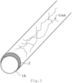
- a cross-sectional schematic diagram of an electrode 100 according to the embodiment is shown in FIG. 1 .
- the electrode 100 includes a support 1 and a catalyst layer 2.
- the catalyst layer 2 is used as a catalyst in electrode reactions for water electrolysis in the embodiments.
- the electrode 100 according to the first embodiment is used as an anode for water electrolysis.
- the electrode 100 can be also used as an oxygen electrode of a fuel cell.
- the electrode 100 according to embodiments can be used as an anode for producing ammonia by electrolysis.
- the electrode 100 according to embodiments can be used as an anode of an electrolyzer for synthesizing ammonia.
- an example of water electrolysis is described in the second embodiment and the other embodiments.
- the electrode 100 according to embodiments can be also used for other than water electrolysis, for example, as an anode of a membrane electrode assembly for electrolysis of synthesizing ammonia so that ultrapure water is supplied to an anode, proton and oxygen is produced in the anode by decomposing water, the produced proton passes through an electrolyte membrane, and ammonia is synthesized by binging nitrogen provided to a cathode, protons, and electrons.
- the electrode 100 according to embodiments can be also used as a cathode for producing hydrogen by electrolyzing ammonia.
- the electrode 100 according to embodiments can be used as a cathode for a hydrogen generation apparatus.
- an example of water electrolysis is described in the first embodiment and the other embodiments.
- the electrode 100 can be also used for other than water electrolysis, for example, as a cathode of a membrane electrode assembly for electrolysis of decomposing ammonia so that ammonia is supplied to a cathode, proton and nitrogen is produced in the cathode by decomposing ammonia, the produced proton passes through an electrolyte membrane, and hydrogen is synthesized by binging protons and electrons.
- the electrode 100 can be also used for an anode of an electrolyzer which electrolyze carbon dioxide to generate organic compounds such as methanol and ethylene and carbon monoxide.
- a porous member having high conductivity is preferable for support 1.
- the support 1 is a porous member through which gas and/or fluid pass.
- a porous support of blub metal is preferable for the support 1 because the electrode 100 is used, for example, an anode of an electrochemical cell. It is preferable that the support 1 includes fibers and the support 1 consists of the fibers.
- the valve metal of the support 1 is Ti which has high durability.
- a Ti mesh, a Ti cloth, or a sintered body of Ti is preferable for the support 1.
- a porosity rate of the support 1 is preferably 20 [%] or more and 95[%] or less and more preferably 40 [%] or more and 90 [%] or less.
- a diameter of fibers of the support 1 is preferably 1 [um] or more and 500 [pm] or less. In view of reactivity and supplying electricity, the diameter of the fibers of the support 1 is more preferably 1 [um] or more and 100 [pm] or less.
- particle diameters of the sintered particles are preferably 1 [um] or more and 500 [pm] or less. In view of reactivity and supplying electricity, the particle diameters of the sintered particles are preferably 1 [um] or more and 500 [pm] or less.
- a coating layer may be provided on the support 1.
- the durability of the electrode 100 can be improved.
- the coating layer is not particularly limited to a material including one or more metals, a material including one or more oxides, a material including one or more nitrides, ceramics, or carbon.
- the durability of the electrode 100 can be more improved when the coating layer has a multi-layered structure with layers having different composition or a structure having graded composition.
- the catalyst layer 2 includes an oxide of noble metal containing Ir and Ru as a main component and an oxide of non-noble metal.
- An intermediate layer which is not shown in figures may be provided between the support 1 and the catalyst layer 2.
- the sum of the amount of the noble metal per area of the catalyst layer 2 is preferably 0.01 [mg/cm 2 ] or more and 3.0 [mg/cm 2 ] or less and more preferably 0.05 [mg/cm 2 ] or more and 0.5 [mg/cm 2 ] or less.
- the sum of the amount of them can be analyzed by ICP-MS (Inductively Coupled Plasma Mass Spectrometry).
- a porosity rate of the catalyst layer 2 is preferably 10 [%] or more and 90 [%] or less and more preferably 30 [%] or more and 70 [%] or less .
- the catalyst layer 2 has a structure that a sheet layer and a gap layer are stacked alternately and repeatedly.
- the sheet layers and the gap layers are stacked in approximately parallel. Most of the gap layers are cavities, and a protruding part of the sheet layers in the gap layers connects the sheet layers.
- the sheet layers are connected with pillars existing in the gap layer.
- the sheet layer is a layer of aggregated catalyst particles in sheet shape. There are cavities also in the sheet layer.
- the gap layer is a region existing between the sheet layers and does not have a structure of catalyst particles aligned in regularly.
- An average thickness of the sheet layer is preferably 4 [nm] or more and 50 [nm] or less.
- An average thickness of the gap layer is preferably 4 [nm] or more and 50 [nm] or less. It is preferable that the average thickness of the sheet layer is thicker than the average thickness of the gap layer. Part of the gap layer may be thicker than part of the sheet layer.
- the catalyst layer 2 preferably includes the Ir oxide or/and the complex oxide of Ir and Ru, and optionally includes the Ru oxide as a noble metal oxide.
- the sum of the concentration of Ir and Ru contained in the catalyst layer 2 to one or more noble metal elements contained in the catalyst layer 2 is preferably 90 [wt%] or more and 100 [%] or less.
- the catalyst layer 2 preferably includes one or more oxides including one or more non-noble metal elements selected the group consisting of Ni, Co, Mn, Fe, Cu, Al, and Zn as a non-noble metal oxide.
- the non-noble metal element included in the catalyst layer 2 preferably includes Ni and optionally includes one or more elements selected from the group consisting of Co, Mn, Fe, Cu, Al, and Zn.
- the sum of the concentration of Ni, Co, and Mn contained in the catalyst layer 2 to one or more non-noble metal elements contained in the catalyst layer 2 is preferably 90 [wt%] or more and 100 [%] or less.
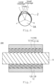
- FIG. 3 is a schematic diagram of the electrode 100.
- FIG. 3 is a magnified schematic diagram of the member that the catalyst layer 2 is provided on the fiber 1A of the support 1.
- the electrode 100 of the embodiment includes the catalyst layer 2 which partly covers the fiber 1A of the support 1. Cracks or/and holes exist on a surface of the catalyst layer 2. Cracks and holes preferably exist on a surface of the catalyst layer 2.
- the catalyst layer 2 is provided on the fiber 1A on the catalyst layer 2 side (electrolyte membrane side). As shown in the schematic diagram of FIG. 3 , the catalyst layer 2 is non provided on the fiber 1A on a side opposite to the catalyst layer 2 side (electrolyte membrane side).
- the sheet layer 2A prevents moving of materials into inside of the catalyst layer 2 because the catalyst layer 2 includes stacked sheet layers 2A.
- the catalyst layer 2 according to the embodiment is not an ideal membrane (such as perfect and defect less membrane) and has the cracks or/and the holes.
- a ratio of the cracks or/and the holes to a surface area of the catalyst layer 2 provided on the fibers 1A is 0.3 [%] or more and 60 [%] or less.
- the ratio of the cracks or/and the holes to a surface area of the catalyst layer 2 provided on the fibers 1A is preferably 1 [%] or more and 50 [%] or less and more preferably 5 [%] or more and 45 [%] or less.
- the ratio of the cracks or/and the holes to a surface area of the catalyst layer 2 provided on the fibers 1A can be determined as follows.
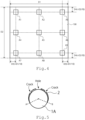
- FIG. 4 shows analysis spots of the support 1. The rate is obtained by observing 9 spots (A1 to A9) on the surface of the the electrode 100.
- Each spot has a square region of 1 mm 2 or more.
- D1 a length of the support 1
- D2 a width of the support 1
- the observing section of SEM is perpendicular to the surface of FIG. 4 .
- a fiber whose cross-section is not clearly observed is excluded for the following observation.
- a length L1 which is a distance between A to B where the catalyst layer 2 is provided on the fiber 1A is determined.
- a length L2 which is a distance excluding the distance where the cracks or/and the holes are provided on the region between A to B.
- Each of L2/L1 of the five fibers 1A is calculated, for a total of 45 L2/L1.
- An average of calculated 45 L2/L1 is regarded as the ratio of the cracks or/and the holes to a surface area of the catalyst layer 2.
- FIG. 5 shows a schematic diagram of a member that the catalyst layer 2 is provided on the fiber 1A.
- the member shown in FIG. 5 has the two cracks and the one hole.
- First a region where the catalyst layer 2 is provided is observed, and the length L1 (outer circumstance length) which is a distance between A length L1 which is a distance between A to B where the catalyst layer 2 is provided on the fiber 1A is obtained.
- FIG. 6 shows a schematic diagram of a member that the catalyst layer 2 is provided on the fiber 1A.
- the member shown in FIG. 6 has the one hole.
- the catalyst layer 2 which presents around the hole is cleaved. First a region where the catalyst layer 2 is provided is observed, and the length L1 (outer circumstance length) between A to B where the catalyst layer 2 is provided on the fiber 1A is obtained.
- the extent of the cleavage is small (small cleavage)
- the region having the cleavage whose extent is small is treated as a region that the catalyst layer 2 is provided on the fiber 1A (not treated as a hole) .
- a region where the catalyst layer 2 is separated from the surface of the fiber 1A for 5 [pm] or more (large cleavage) is treated as a part of a hole or a crack where the catalyst layer 2 is not provided on the fiber 1A. Then, a length L3 of the fiber 1A from C to D where the fiber 1A is open due to the cracks and the hole is obtained, L2 is calculated by L1 - L3 (subtract L3 from L1), and L2/L1 is calculated.
- the one or more cracks exist on the surface of the catalyst layer 2.
- the crack exist, catalyst defects is present but a large open area on a cross-section of the catalyst layer 2 is formed.
- the catalyst utilization efficiency is increased.
- the catalyst layer 2 has a crack whose length is 5 times or more of the diameter of the fiber 1A.
- the amount of each metal element contained in the catalyst layer 2 can be analyzed by ICP-MS (Inductively Coupled Plasma Mass Spectrometry).
- the electrode 100 that the catalyst layer 2 has cracks and/or holes is obtained, for example, the following method.
- a manufacturing method for electrode 100 that the catalyst layer 2 has cracks and/or holes includes a step of forming a substantial precursor of the sheet layer including a noble metal oxide and a substantial precursor of the gap layer including a non-noble metal oxide alternately, and a step of dissolving the non-noble metal oxide with an acid treatment. After the dissolving with acid, heating process is performed. The heating process is preferably performed in a non-reducing atmosphere (for example in the air). When the heating temperature is too low, the cracks or/and the holes are hardly formed. When the heating temperature is too high, the the catalyst layer 2 is easily removed due to the cleavage of the catalyst layer 2.
- a second embodiment relates to a membrane electrode assembly (MEA).
- MEA membrane electrode assembly
- FIG. 7 A schematic diagram of a membrane electrode assembly 200 according to the embodiment is shown in FIG. 7 .
- the membrane electrode assembly 200 includes a first electrode 11, a second electrode 12, and an electrolyte membrane 13.
- the first electrode 11 is an anode electrode preferably.
- the second electrode is a cathode electrode preferably.
- the electrode 100 is preferably used for the first electrode 11.
- the membrane electrode assembly 200 of embodiments is preferably used for an electrochemical cell or a stack generating hydrogen or oxygen.
- the electrode 100 according to the first embodiment including the support 1 and the catalyst layer 2 for the first electrode 11.
- the catalyst layer 2 of the electrode 100 used for the first electrode 11 is provided on the electrolyte membrane 13 side.
- the catalyst layer 2 is preferably in direct contact with the electrolyte membrane 13.
- the electrolyte membrane 13 may be invaded into cracks and/or holes of the catalyst layer 2.
- a porous ratio of the first catalyst layer 11B is preferably 10 [%] or more and 90[%] or less and more preferably 30 [%] or more and 70 [%] or less.
- the amount of metal per area of the first catalyst layer 11B is within the above range and has high porosity and hydrogen which is generated at the cathode (second electrode 12B) passes through the electrolyte membrane 13 and leaks into the anode (the first electrode 11), hydrogen is easily to pass through the first catalyst layer 11B and the first substrate 11A since the first catalyst layer 11B has low density.
- leakage measures according to the embodiment are taken, hydrogen leakage can be effectively suppressed even if the first catalyst layer 11B which is easily to leak hydrogen due to the high porous is used.
- the membrane electrode assembly 200 according to the embodiment can effectively suppress hydrogen leakage.
- the second electrode 12 includes a second support 12A and a second catalyst layer 12B.
- the second catalyst layer 12B is provided on the second support 12A.
- the second catalyst layer 12B is provided on the electrolyte membrane 13 side.
- the second catalyst layer 12B is preferably in direct contact with the electrolyte membrane 13.
- a porous member having high conductivity is preferable for the second support 12A.
- the second support 12A is a porous member through which gas and/or fluid pass.
- the second support 12A is, for example, a carbon paper or a metal mesh.
- a porous support of blub metal is preferable for the metal mesh.
- the second support 12A may include a carbon layer (MPL layer) including carbon fine particles and a water-repellent resin (fluororesin such as PTFE and nafion).
- MPL layer carbon layer
- fluororesin such as PTFE and nafion
- the carbon layer is provided between, for example, the carbon paper and the second catalyst layer 12B.
- the second catalyst layer 12B includes catalyst metal. It is preferable that the second catalyst layer 12B is particles of catalyst metal which is not supported on a carrier.
- the second catalyst layer 12B is preferably a porous catalyst layer.
- the catalyst metal of the second catalyst layer 12B is not limited to, for example, one or more metal elements selected from the group consisting of Pt, Rh, OS, Ir, Pd, and Au.
- the second catalyst layer 12B preferably includes one or more metal elements selected from the catalyst materials. It is preferable that the catalyst metal is metal, alloy, or metal oxide. It is preferable that the second catalyst layer 12B includes catalyst units of a sheet catalyst layer and a gap layer stacked alternately.
- the sum of the amount of metal per area of the second catalyst layer 12B is preferably 0.02 [mg/cm 2 ] or more and 1.0 [mg/cm 2 ] or less and more preferably 0.05 [mg/cm 2 ] or more and 0.5 [mg/cm 2 ] or less.
- the sum of the amount of them can be analyzed by ICP-MS (Inductively Coupled Plasma Mass Spectrometry).
- a porosity rate of the second catalyst layer 12B is preferably 10 [%] or more and 90 [%] or less and more preferably 30 [%] or more and 70 [%] or less.
- the electrolyte membrane 13 has proton conductivity.
- fluorinated polymer having one or more organic groups selected from the group consisting of a sulfonic acid group, a sulfonimide group, and a sulfate group or an aromatic hydrocarbon based polymer is preferable.
- the fluorinated polymer having a sulfonic acid group is preferable.
- NAFION (trademark, DuPont), FLEMION (trademark, Asahi Glass Co., Ltd.), SELEMION (trademark, Asahi Glass Co., Ltd.), Aquivion (trademark, Solvay Specialty Polymers) or Aciplex (trademark, Asahi Kasei Corp.) or the like can be used as the fluorinated polymer having the sulfonic acid group.
- a thickness of the electrolyte membrane 13 is chosen appropriately in consideration of a membrane permeability, durability and the like.
- the thickness of the electrolyte membrane 13 is preferably 20 [ ⁇ m] or more and 500 [ ⁇ m] or less, more preferably 50 [um] or more and 300 [ ⁇ m] or less, and still more preferably 80 [ ⁇ m] or more and 200 [ ⁇ m] or less.
- the electrolyte membrane 13 preferably includes a noble metal region on the first electrode 11 side.
- the noble metal region includes noble metal particles.
- the noble metal region is preferably present on the surface of the electrolyte membrane 13.
- the noble metal region preferably consists of one region.
- the noble metal region may include divided regions.
- the noble metal particles are particles including one or more kinds of noble metal elements selected from the group consisting of Pt, Re, Rh, Ir, Pd, and Ru.
- the noble metal particles may include or optionally include alloy particles containing one or more kinds of noble metal elements selected from the group consisting of Pt, Re, Rh, Ir, Pd, and Ru. It is preferable that the noble metal particles are particles of one kind of noble metal element selected from the group consisting of Pt, Re, Rh, Ir, Pd, and Ru. It is preferable that the noble metal particles are particles of Pt. It is preferable that the noble metal particles are particles of Re. It is preferable that the noble metal particles are particles of Rh. It is preferable that the noble metal particles are particles of Ir. It is preferable that the noble metal particles are particles of Pd. It is preferable that the noble metal particles are particles of Ru.
- the noble metal particles oxidize hydrogen which is generated on the cathode side and passes through the electrolyte membrane 13.
- the noble metal particles reduce leakage of hydrogen.
- the extracted hydrogen from the cathode side is not easily oxidized because the noble metal particles is provided on the anode side.
- the region where the noble metal particles are included may be also provided on the second electrode 12 (cathode) side of the electrolyte membrane 13.
- An average circumscribed circle diameter of the noble metal particles is preferably 0.5 [nm] or more and 50 [nm] or less, 1.0 [nm] or more and 10 [nm] or less, and still more preferably 1 [nm] or more and 5 [nm] or less.
- a long-term operation with high activity becomes available by using the electrode 100 having high durability for the anode of the membrane electrode assembly 200.
- a third embodiment relates to electrochemical cell.
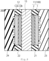
- a cross-sectional diagram of the electrochemical cell 300 according to the third embodiment is illustrated in FIG. 8 .
- the electrochemical cell will be described as an example of water electrolysis. Hydrogen is also generated by decomposition of ammonia other than water.
- the electrochemical cell 300 includes a first electrode (anode) 11, a second electrode (cathode) 12, an electrolyte membrane 13, a gasket 21, a gasket 22, a separator 23, and a separator 23.
- a seal member of the first electrode 11 can be used for the gasket 21.
- a seal member of the second electrode 12 can be used for the gasket 22.
- the membrane electrode assembly 200 that the first electrode (anode) 11, the second electrode (cathode) 12, and the electrolyte membrane 13 are bonded is preferably used for the electrochemical cell 300.
- An anode feeder may be provided separately from the separator 23.
- a cathode feeder may be provided separately from the separator 24.
- a power supply which is not shown in figures is connected to the separator 23 and the separator 24, and reactions occur in the anode 11 and the cathode 12.
- water is supplied to the anode 11 and water is decomposed to proton, oxygen, and electron at the anode 11.
- the support for the electrode and the feeder are porous members, and the porous members function as a passage board.
- the formed water and un-reacted water are extracted, and proton and electron are used for a cathode reaction.
- the cathode reaction is that proton and electron react, and hydrogen is formed.
- the formed hydrogen and/or formed oxygen can be used as a fuel-cell fuel or the other apparatus.
- FIG. 9 illustrate a schematic cross-sectional diagram of a stack.
- the stack 400 according to the fourth embodiment illustrated in FIG. 9 is configured so that two or more of the MEAs 200 or the electrochemical cells 300 are connected in series. Tightening plates 31 and 32 are attached to both ends of the electrochemical cells 300.
- the amount of hydrogen generated in the electrochemical cell 300 composed of a single MEA 200 is small. Therefore, a large amount of hydrogen can be obtained by structuring the stack 400 in which two or more of the electrochemical cells are connected in series.
- FIG. 10 illustrates a conceptual diagram of the electrolyzer according to the fifth embodiment.
- the electrolyzer 500 uses the electrochemical cell 300 or the stack 400.
- the electrolyzer of FIG. 10 is used for water decomposition.
- the following is an explanation of an electrolyzer using a water electrolyzer as an example. For example, when hydrogen is generated from ammonia, an apparatus having the other structure using the electrode 100.
- water electrolysis cells stacked in series are used as the stack 400 for water electrolysis.
- a power supply 41 is attached to the stack 400, and voltage is applied between the anode and the cathode.
- a gas-liquid separator 42 for separating generated gas and unreacted water and a mixing tank 43 are connected to the anode side of the stack 400 for water electrolysis and water is sent to the mixing tank 43 by a pump 46 from an ion exchanged water producing apparatus 44 that supplies water for mixing in the mixing tank 43, and water is circulated to the anode mixed in the mixing tank 43 through a check valve 47 from the gas-liquid separator 42. Oxygen generated in the anode passes through the gas-liquid separator 42 so that an oxygen gas is obtained.
- a hydrogen purification device 49 is connected to the cathode side subsequent to a gas-liquid separator 48 to obtain high purity hydrogen. Impurities are discharged via a path having a valve 50 connected to the hydrogen purification device 49.
- a valve 50 connected to the hydrogen purification device 49.
- a 200 [um] thick of a titanium un-woven fabric substrate with a size of 25 [cm] ⁇ 25 [cm] is used as the support 1.
- a precursor of a sheet layer is formed by sputtering iridium on the titanium support.
- a precursor of a gap layer is formed by sputtering only Ni.
- the forming step of the sheet layer and the forming step of the gap layer are repeated for 22 times, and a laminated structure is obtained so that Ir amount per area is 0.2 [mg/cm 2 ].
- the forming conditions of the sheet layer and the gap layer are shown in Table 1 and Table 2. After the sputtering, the sputtered member is washed with sulfuric acid to obtain a laminated structure that the Ni oxide is partly eluted.
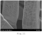
- a SEM image of the electrode 100 of Example A-1 is shown in FIG. 11 .
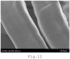
- a SEM image of the electrode 100 of Comparative Example A-1 is shown in FIG. 12 .
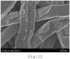
- a SEM image of the electrode 100 of Comparative Example A-2 is shown in FIG. 13 .
- a carbon paper (Toray060 manufactured by Toray Industries, Inc.) with a size of 25 [cm] ⁇ 25 [cm] having 190 [um] thick of a MPL layer is prepared for a support of a cathode.
- a catalyst layer having a laminated structure including gap layers formed by sputtering is formed on the support so that the loading density of Pt becomes 0.1 [mg / cm 2 ] to obtain an electrode having porous catalyst layer. This electrode is used as the standard cathode of Examples and Comparative Examples.
- Nafion115 manufactured by Chemours Company with a size of 30 [cm] ⁇ 30 [cm] is used as an electrolyte membrane, the electrolyte membrane is sandwiched between the anode and the cathode, and hot pressing is performed.
- the sandwiched member is set in a hot pressing apparatus, pressing is performed at 160 [°C] and 20 [kg/cm 2 ] for 3 minutes, and additional pressing is performed at 25 [°C] and 20 [kg/cm 2 ] for 3 minutes to obtain MEA.
- the obtained MEA 200 is set between two separators having flow passage to produce a PEEC single cell (electrochemical cell). Additionally, a back pressure valve is attached on the exit of the separators having flow passage on hydrogen side, and internal pressure can be increased.
- Example A and Comparative Example A is evaluated.
- the obtained single cell is conditioned for one day. Thereafter, the single cell is maintained at 60 [°C] and 0.05 [L/min] of ultra-pure water is supplied to the anode.
- the cell voltage (VC) is measured after operating 48 hours with applying current between the anode and the cathode using a power supply at a current density of 2 [A / cm 2 ].
- Table 4 shows the cell voltage (VC).
- the anode is manufactured as same as conditions excluding the heating treatment as shown in table 5, and the MEA is manufactured by as same as method of Example A.
- the amount of charge of the MEA was measured by cyclic voltammetry.
- the measurement of the cyclic voltammetry is performed where voltage range is between 0.2 [V] to 1.2 [V], a scanning speed is 50 [mV/sec], and number of cycles is 10.
- the total area of the cyclic voltammogram of 10th cycle is calculated. The total area is regarded as the amount of charge of the catalyst layer.
- the amount of charge is shown in table 6.
Landscapes
- Chemical & Material Sciences (AREA)
- Engineering & Computer Science (AREA)
- Chemical Kinetics & Catalysis (AREA)
- Electrochemistry (AREA)
- Materials Engineering (AREA)
- Metallurgy (AREA)
- Organic Chemistry (AREA)
- Inorganic Chemistry (AREA)
- Electrolytic Production Of Non-Metals, Compounds, Apparatuses Therefor (AREA)
- Electrodes For Compound Or Non-Metal Manufacture (AREA)
Abstract
An electrode according to an embodiment includes a support and a catalyst layer including a sheet layer and a gap layer stacked alternately. Cracks or/and holes exist in the catalyst layer.
Description
- The present embodiments relate to an electrode, a membrane electrode assembly, an electrochemical cell, a stack, and an electrolyzer.
- In recent years, electrochemical cells have been actively studied. Among electrochemical cells, for example, a polymer electrolyte membrane electrolysis cell (PEMEC) is expected to be used for hydrogen generation in a large-scale energy storage system. In order to ensure sufficient durability and electrolytic properties, platinum (Pt) nanoparticle catalysts are generally used for PEMEC cathodes, and noble metal catalysts such as iridium (Ir) nanoparticle catalysts are used for positive electrodes. Additionally, a method for obtaining hydrogen from ammonia is also considered. In addition, a method for obtaining organic material or carbon monoxide by electrolysis of carbon dioxide is also considered.
-
-
FIG. 1 is a schematic diagram of an embodiment according to an embodiment. -
FIG. 2 is a schematic diagram of a catalyst layer according to an embodiment. -
FIG. 3 is a schematic diagram of an embodiment according to an embodiment. -
FIG. 4 shows analysis spots of an electrode according to an embodiment. -
FIG. 5 is a schematic diagram of a member that a catalyst layer is provided on fibers according to an embodiment. -
FIG. 6 is a schematic diagram of an embodiment according to an embodiment. -
FIG. 7 is a schematic diagram of a membrane electrode assembly according to an embodiment. -
FIG. 8 is a schematic diagram of an electrochemical cell according to an embodiment. -
FIG. 9 is a schematic diagram of a stack according to an embodiment. -
FIG. 10 is a conceptual diagram of an electrolyzer according to an embodiment. -
FIG. 11 is a SEM image of an electrode of an example according to an embodiment. -
FIG. 12 is a SEM image of an electrode of a comparative example according to an embodiment. -
FIG. 13 is a SEM image of an electrode of a comparative example according to an embodiment. - An electrode according to an embodiment includes a support and a catalyst layer including a sheet layer and a gap layer stacked alternately. Cracks or/and holes exist in the catalyst layer.
- Hereinafter, the embodiments will be described with reference to the drawings.
- It is to be noted that the same reference numerals are given to common components throughout the embodiments, and redundant explanations are omitted.
- In the specification, values at 25 [°C] and 1 atm (atmosphere) are shown. Each thickness of the members represents an average of distance in a stacking direction.
- The first embodiment relates to an electrode. A cross-sectional schematic diagram of an
electrode 100 according to the embodiment is shown inFIG. 1 . Theelectrode 100 includes asupport 1 and acatalyst layer 2. Thecatalyst layer 2 is used as a catalyst in electrode reactions for water electrolysis in the embodiments. - The
electrode 100 according to the first embodiment is used as an anode for water electrolysis. When thecatalyst layer 2 further includes a catalyst for a fuel cell, theelectrode 100 can be also used as an oxygen electrode of a fuel cell. Theelectrode 100 according to embodiments can be used as an anode for producing ammonia by electrolysis. Theelectrode 100 according to embodiments can be used as an anode of an electrolyzer for synthesizing ammonia. Hereinafter, an example of water electrolysis is described in the second embodiment and the other embodiments. Theelectrode 100 according to embodiments can be also used for other than water electrolysis, for example, as an anode of a membrane electrode assembly for electrolysis of synthesizing ammonia so that ultrapure water is supplied to an anode, proton and oxygen is produced in the anode by decomposing water, the produced proton passes through an electrolyte membrane, and ammonia is synthesized by binging nitrogen provided to a cathode, protons, and electrons. Theelectrode 100 according to embodiments can be also used as a cathode for producing hydrogen by electrolyzing ammonia. Theelectrode 100 according to embodiments can be used as a cathode for a hydrogen generation apparatus. Hereinafter, an example of water electrolysis is described in the first embodiment and the other embodiments. Theelectrode 100 according to embodiments can be also used for other than water electrolysis, for example, as a cathode of a membrane electrode assembly for electrolysis of decomposing ammonia so that ammonia is supplied to a cathode, proton and nitrogen is produced in the cathode by decomposing ammonia, the produced proton passes through an electrolyte membrane, and hydrogen is synthesized by binging protons and electrons. Theelectrode 100 can be also used for an anode of an electrolyzer which electrolyze carbon dioxide to generate organic compounds such as methanol and ethylene and carbon monoxide. - A porous member having high conductivity is preferable for
support 1. Thesupport 1 is a porous member through which gas and/or fluid pass. A porous support of blub metal is preferable for thesupport 1 because theelectrode 100 is used, for example, an anode of an electrochemical cell. It is preferable that thesupport 1 includes fibers and thesupport 1 consists of the fibers. A porous support containing one or more metals selected from the group consisting of titanium (Ti), aluminum (Al), tantalum (Ta), niobium (Nb), hafnium (Hf), zirconium (Zr), zinc (Zn), tungsten (W), bismuth (Bi), and antimony (Sb) or a porous support consisting of one kind of metals selected from consisting of titanium (Ti), aluminum (Al), tantalum (Ta), niobium (Nb), hafnium (Hf), zirconium (Zr), zinc (Zn), tungsten (W), bismuth (Bi), and antimony (Sb) is preferable for the porous support of valve metal. - It is preferable that the valve metal of the
support 1 is Ti which has high durability. For example, a Ti mesh, a Ti cloth, or a sintered body of Ti is preferable for thesupport 1. When movability of materials is considered, a porosity rate of thesupport 1 is preferably 20 [%] or more and 95[%] or less and more preferably 40 [%] or more and 90 [%] or less. When, for example, a metal woven cloth with intertwined metal fibers is used as thesupport 1, a diameter of fibers of thesupport 1 is preferably 1 [um] or more and 500 [pm] or less. In view of reactivity and supplying electricity, the diameter of the fibers of thesupport 1 is more preferably 1 [um] or more and 100 [pm] or less. When thesupport 1 is sintered particles, particle diameters of the sintered particles are preferably 1 [um] or more and 500 [pm] or less. In view of reactivity and supplying electricity, the particle diameters of the sintered particles are preferably 1 [um] or more and 500 [pm] or less. - A coating layer may be provided on the
support 1. When a coating layer having electric conductivity is finely provided, the durability of theelectrode 100 can be improved. The coating layer is not particularly limited to a material including one or more metals, a material including one or more oxides, a material including one or more nitrides, ceramics, or carbon. The durability of theelectrode 100 can be more improved when the coating layer has a multi-layered structure with layers having different composition or a structure having graded composition. - The
catalyst layer 2 includes an oxide of noble metal containing Ir and Ru as a main component and an oxide of non-noble metal. An intermediate layer which is not shown in figures may be provided between thesupport 1 and thecatalyst layer 2. - The sum of the amount of the noble metal per area of the
catalyst layer 2 is preferably 0.01 [mg/cm2] or more and 3.0 [mg/cm2] or less and more preferably 0.05 [mg/cm2] or more and 0.5 [mg/cm2] or less. The sum of the amount of them can be analyzed by ICP-MS (Inductively Coupled Plasma Mass Spectrometry). - A porosity rate of the
catalyst layer 2 is preferably 10 [%] or more and 90 [%] or less and more preferably 30 [%] or more and 70 [%] or less . - The
catalyst layer 2 has a structure that a sheet layer and a gap layer are stacked alternately and repeatedly. The sheet layers and the gap layers are stacked in approximately parallel. Most of the gap layers are cavities, and a protruding part of the sheet layers in the gap layers connects the sheet layers. The sheet layers are connected with pillars existing in the gap layer. - The sheet layer is a layer of aggregated catalyst particles in sheet shape. There are cavities also in the sheet layer. The gap layer is a region existing between the sheet layers and does not have a structure of catalyst particles aligned in regularly.
- An average thickness of the sheet layer is preferably 4 [nm] or more and 50 [nm] or less. An average thickness of the gap layer is preferably 4 [nm] or more and 50 [nm] or less. It is preferable that the average thickness of the sheet layer is thicker than the average thickness of the gap layer. Part of the gap layer may be thicker than part of the sheet layer.
- The
catalyst layer 2 preferably includes the Ir oxide or/and the complex oxide of Ir and Ru, and optionally includes the Ru oxide as a noble metal oxide. The sum of the concentration of Ir and Ru contained in thecatalyst layer 2 to one or more noble metal elements contained in thecatalyst layer 2 is preferably 90 [wt%] or more and 100 [%] or less. - The
catalyst layer 2 preferably includes one or more oxides including one or more non-noble metal elements selected the group consisting of Ni, Co, Mn, Fe, Cu, Al, and Zn as a non-noble metal oxide. The non-noble metal element included in thecatalyst layer 2 preferably includes Ni and optionally includes one or more elements selected from the group consisting of Co, Mn, Fe, Cu, Al, and Zn. The sum of the concentration of Ni, Co, and Mn contained in thecatalyst layer 2 to one or more non-noble metal elements contained in thecatalyst layer 2 is preferably 90 [wt%] or more and 100 [%] or less. -
FIG. 3 is a schematic diagram of theelectrode 100.FIG. 3 is a magnified schematic diagram of the member that thecatalyst layer 2 is provided on thefiber 1A of thesupport 1. As shown in the schematic diagram ofFIG. 3 , theelectrode 100 of the embodiment includes thecatalyst layer 2 which partly covers thefiber 1A of thesupport 1. Cracks or/and holes exist on a surface of thecatalyst layer 2. Cracks and holes preferably exist on a surface of thecatalyst layer 2. - As shown in the schematic diagram of
FIG. 3 , thecatalyst layer 2 is provided on thefiber 1A on thecatalyst layer 2 side (electrolyte membrane side). As shown in the schematic diagram ofFIG. 3 , thecatalyst layer 2 is non provided on thefiber 1A on a side opposite to thecatalyst layer 2 side (electrolyte membrane side). - There is a possibility that the
sheet layer 2A prevents moving of materials into inside of thecatalyst layer 2 because thecatalyst layer 2 includes stacked sheet layers 2A. It is preferable that thecatalyst layer 2 according to the embodiment is not an ideal membrane (such as perfect and defect less membrane) and has the cracks or/and the holes. A ratio of the cracks or/and the holes to a surface area of thecatalyst layer 2 provided on thefibers 1A is 0.3 [%] or more and 60 [%] or less. When the cracks or/and the holes exist, a catalyst utilization efficiency is increased because materials are easy to move into inside of thecatalyst layer 2. The cracks are line-shaped defects formed on thecatalyst layer 2. The holes are defects other than the cracks of thecatalyst layer 2. - If 20 layers of virtual perfect sheet catalyst layers which have no cracks and holes are stacked, a top layer of them can reacts but rest of layers hardly react. When the sheet layers 2A have cracks, the electrolysis reaction is promoted due to immersing water or the like into the cracks . In view of the above, the ratio of the cracks or/and the holes to a surface area of the
catalyst layer 2 provided on thefibers 1A is preferably 1 [%] or more and 50 [%] or less and more preferably 5 [%] or more and 45 [%] or less. - The ratio of the cracks or/and the holes to a surface area of the
catalyst layer 2 provided on thefibers 1A can be determined as follows.FIG. 4 shows analysis spots of thesupport 1. The rate is obtained by observing 9 spots (A1 to A9) on the surface of the theelectrode 100. - Each spot has a square region of 1 mm2 or more. When a length of the
support 1 is denoted by D1 and a width of thesupport 1 is denoted by D2 (D1 ≥ D2) as shown inFIG. 4 , each of the analysis spots A1 to A9 is an area centered on each of the nine intersections of virtual lines, where two of the virtual lines are drawn from both edges facing to the width direction of thesupport 1 to the respective interior at distance D3 (D3 = D1/10), two of the virtual lines are drawn from both edges facing to the length direction of thesupport 1 to the respective interior at distance D4 (D4 = D2/10), one of the virtual lines is drawn parallel to the width direction at center of thesupport 1, and one of the virtual lines is drawn parallel to the length direction at center of thesupport 1. The observing section of SEM is perpendicular to the surface ofFIG. 4 . - Five
fibers 1A on which thecatalyst layer 2 is provided and which are nearest to the center of the cross-sectional image of each of the spots are selected. A fiber whose cross-section is not clearly observed is excluded for the following observation. A length L1 which is a distance between A to B where thecatalyst layer 2 is provided on thefiber 1A is determined. A length L2 which is a distance excluding the distance where the cracks or/and the holes are provided on the region between A to B. Each of L2/L1 of the fivefibers 1A is calculated, for a total of 45 L2/L1. An average of calculated 45 L2/L1 is regarded as the ratio of the cracks or/and the holes to a surface area of thecatalyst layer 2. -
FIG. 5 shows a schematic diagram of a member that thecatalyst layer 2 is provided on thefiber 1A. The member shown inFIG. 5 has the two cracks and the one hole. First a region where thecatalyst layer 2 is provided is observed, and the length L1 (outer circumstance length) which is a distance between A length L1 which is a distance between A to B where thecatalyst layer 2 is provided on thefiber 1A is obtained. A length L3 of thefiber 1A where thefiber 1A is open due to the cracks and the hole is obtained, L2 is calculated by L1 - L3 (subtract L3 from L1), and L2/L1 is calculated. -
FIG. 6 shows a schematic diagram of a member that thecatalyst layer 2 is provided on thefiber 1A. The member shown inFIG. 6 has the one hole. Thecatalyst layer 2 which presents around the hole is cleaved. First a region where thecatalyst layer 2 is provided is observed, and the length L1 (outer circumstance length) between A to B where thecatalyst layer 2 is provided on thefiber 1A is obtained. When the extent of the cleavage is small (small cleavage), the region having the cleavage whose extent is small is treated as a region that thecatalyst layer 2 is provided on thefiber 1A (not treated as a hole) . A region where thecatalyst layer 2 is separated from the surface of thefiber 1A for 5 [pm] or more (large cleavage) is treated as a part of a hole or a crack where thecatalyst layer 2 is not provided on thefiber 1A. Then, a length L3 of thefiber 1A from C to D where thefiber 1A is open due to the cracks and the hole is obtained, L2 is calculated by L1 - L3 (subtract L3 from L1), and L2/L1 is calculated. - It is preferable that the one or more cracks exist on the surface of the
catalyst layer 2. When the crack exist, catalyst defects is present but a large open area on a cross-section of thecatalyst layer 2 is formed. When the length of the crack is long, the catalyst utilization efficiency is increased. It is preferable that thecatalyst layer 2 has a crack whose length is 5 times or more of the diameter of thefiber 1A. - The amount of each metal element contained in the
catalyst layer 2 can be analyzed by ICP-MS (Inductively Coupled Plasma Mass Spectrometry). - The
electrode 100 that thecatalyst layer 2 has cracks and/or holes is obtained, for example, the following method. A manufacturing method forelectrode 100 that thecatalyst layer 2 has cracks and/or holes includes a step of forming a substantial precursor of the sheet layer including a noble metal oxide and a substantial precursor of the gap layer including a non-noble metal oxide alternately, and a step of dissolving the non-noble metal oxide with an acid treatment. After the dissolving with acid, heating process is performed. The heating process is preferably performed in a non-reducing atmosphere (for example in the air). When the heating temperature is too low, the cracks or/and the holes are hardly formed. When the heating temperature is too high, the thecatalyst layer 2 is easily removed due to the cleavage of thecatalyst layer 2. - A second embodiment relates to a membrane electrode assembly (MEA). A schematic diagram of a
membrane electrode assembly 200 according to the embodiment is shown inFIG. 7 . Themembrane electrode assembly 200 includes afirst electrode 11, asecond electrode 12, and anelectrolyte membrane 13. Thefirst electrode 11 is an anode electrode preferably. - The second electrode is a cathode electrode preferably. The
electrode 100 is preferably used for thefirst electrode 11. Themembrane electrode assembly 200 of embodiments is preferably used for an electrochemical cell or a stack generating hydrogen or oxygen. - It is preferable that the
electrode 100 according to the first embodiment including thesupport 1 and thecatalyst layer 2 for thefirst electrode 11. Thecatalyst layer 2 of theelectrode 100 used for thefirst electrode 11 is provided on theelectrolyte membrane 13 side. Thecatalyst layer 2 is preferably in direct contact with theelectrolyte membrane 13. Theelectrolyte membrane 13 may be invaded into cracks and/or holes of thecatalyst layer 2. - A porous ratio of the
first catalyst layer 11B (the catalyst layer 2) is preferably 10 [%] or more and 90[%] or less and more preferably 30 [%] or more and 70 [%] or less. When the amount of metal per area of thefirst catalyst layer 11B is within the above range and has high porosity and hydrogen which is generated at the cathode (second electrode 12B) passes through theelectrolyte membrane 13 and leaks into the anode (the first electrode 11), hydrogen is easily to pass through thefirst catalyst layer 11B and thefirst substrate 11A since thefirst catalyst layer 11B has low density. When leakage measures according to the embodiment are taken, hydrogen leakage can be effectively suppressed even if thefirst catalyst layer 11B which is easily to leak hydrogen due to the high porous is used. When a catalyst layer which is not easily to leak hydrogen is used for thefirst catalyst layer 11B, themembrane electrode assembly 200 according to the embodiment can effectively suppress hydrogen leakage. - The
second electrode 12 includes asecond support 12A and asecond catalyst layer 12B. Thesecond catalyst layer 12B is provided on thesecond support 12A. Thesecond catalyst layer 12B is provided on theelectrolyte membrane 13 side. Thesecond catalyst layer 12B is preferably in direct contact with theelectrolyte membrane 13. - A porous member having high conductivity is preferable for the
second support 12A. Thesecond support 12A is a porous member through which gas and/or fluid pass. Thesecond support 12A is, for example, a carbon paper or a metal mesh. A porous support of blub metal is preferable for the metal mesh. A porous support containing one or more metals selected from the group consisting of titanium (Ti), aluminum (Al), tantalum (Ta), niobium (Nb), hafnium (Hf), zirconium (Zr), zinc (Zn), tungsten (W), bismuth (Bi), and antimony (Sb) or a porous support consisting of one kind of metals selected from consisting of titanium (Ti), aluminum (Al), tantalum (Ta), niobium (Nb), hafnium (Hf), zirconium (Zr), zinc (Zn), tungsten (W), bismuth (Bi), and antimony (Sb). Thesecond support 12A may include a carbon layer (MPL layer) including carbon fine particles and a water-repellent resin (fluororesin such as PTFE and nafion). The carbon layer is provided between, for example, the carbon paper and thesecond catalyst layer 12B. - The
second catalyst layer 12B includes catalyst metal. It is preferable that thesecond catalyst layer 12B is particles of catalyst metal which is not supported on a carrier. Thesecond catalyst layer 12B is preferably a porous catalyst layer. The catalyst metal of thesecond catalyst layer 12B is not limited to, for example, one or more metal elements selected from the group consisting of Pt, Rh, OS, Ir, Pd, and Au. Thesecond catalyst layer 12B preferably includes one or more metal elements selected from the catalyst materials. It is preferable that the catalyst metal is metal, alloy, or metal oxide. It is preferable that thesecond catalyst layer 12B includes catalyst units of a sheet catalyst layer and a gap layer stacked alternately. - The sum of the amount of metal per area of the
second catalyst layer 12B is preferably 0.02 [mg/cm2] or more and 1.0 [mg/cm2] or less and more preferably 0.05 [mg/cm2] or more and 0.5 [mg/cm2] or less. The sum of the amount of them can be analyzed by ICP-MS (Inductively Coupled Plasma Mass Spectrometry). - A porosity rate of the
second catalyst layer 12B is preferably 10 [%] or more and 90 [%] or less and more preferably 30 [%] or more and 70 [%] or less. - The
electrolyte membrane 13 has proton conductivity. As theelectrolyte membrane 13, fluorinated polymer having one or more organic groups selected from the group consisting of a sulfonic acid group, a sulfonimide group, and a sulfate group or an aromatic hydrocarbon based polymer is preferable. As theelectrolyte membrane 13, the fluorinated polymer having a sulfonic acid group is preferable. NAFION (trademark, DuPont), FLEMION (trademark, Asahi Glass Co., Ltd.), SELEMION (trademark, Asahi Glass Co., Ltd.), Aquivion (trademark, Solvay Specialty Polymers) or Aciplex (trademark, Asahi Kasei Corp.) or the like can be used as the fluorinated polymer having the sulfonic acid group. - A thickness of the
electrolyte membrane 13 is chosen appropriately in consideration of a membrane permeability, durability and the like. In view of the strength, anti-solubility, and output characteristics of MEA, the thickness of theelectrolyte membrane 13 is preferably 20 [µm] or more and 500 [µm] or less, more preferably 50 [um] or more and 300 [µm] or less, and still more preferably 80 [µm] or more and 200 [µm] or less. - The
electrolyte membrane 13 preferably includes a noble metal region on thefirst electrode 11 side. The noble metal region includes noble metal particles. The noble metal region is preferably present on the surface of theelectrolyte membrane 13. The noble metal region preferably consists of one region. The noble metal region may include divided regions. - The noble metal particles are particles including one or more kinds of noble metal elements selected from the group consisting of Pt, Re, Rh, Ir, Pd, and Ru. The noble metal particles may include or optionally include alloy particles containing one or more kinds of noble metal elements selected from the group consisting of Pt, Re, Rh, Ir, Pd, and Ru. It is preferable that the noble metal particles are particles of one kind of noble metal element selected from the group consisting of Pt, Re, Rh, Ir, Pd, and Ru. It is preferable that the noble metal particles are particles of Pt. It is preferable that the noble metal particles are particles of Re. It is preferable that the noble metal particles are particles of Rh. It is preferable that the noble metal particles are particles of Ir. It is preferable that the noble metal particles are particles of Pd. It is preferable that the noble metal particles are particles of Ru.
- The noble metal particles oxidize hydrogen which is generated on the cathode side and passes through the
electrolyte membrane 13. The noble metal particles reduce leakage of hydrogen. The extracted hydrogen from the cathode side is not easily oxidized because the noble metal particles is provided on the anode side. The region where the noble metal particles are included may be also provided on the second electrode 12 (cathode) side of theelectrolyte membrane 13. - An average circumscribed circle diameter of the noble metal particles is preferably 0.5 [nm] or more and 50 [nm] or less, 1.0 [nm] or more and 10 [nm] or less, and still more preferably 1 [nm] or more and 5 [nm] or less.
- A long-term operation with high activity becomes available by using the
electrode 100 having high durability for the anode of themembrane electrode assembly 200. - A third embodiment relates to electrochemical cell. A cross-sectional diagram of the
electrochemical cell 300 according to the third embodiment is illustrated inFIG. 8 . Hereinafter, the electrochemical cell will be described as an example of water electrolysis. Hydrogen is also generated by decomposition of ammonia other than water. - The
electrochemical cell 300 according to the third embodiment as illustrated inFIG. 8 includes a first electrode (anode) 11, a second electrode (cathode) 12, anelectrolyte membrane 13, agasket 21, agasket 22, aseparator 23, and aseparator 23. A seal member of thefirst electrode 11 can be used for thegasket 21. A seal member of thesecond electrode 12 can be used for thegasket 22. - The
membrane electrode assembly 200 that the first electrode (anode) 11, the second electrode (cathode) 12, and theelectrolyte membrane 13 are bonded is preferably used for theelectrochemical cell 300. An anode feeder may be provided separately from theseparator 23. A cathode feeder may be provided separately from theseparator 24. - In the
electrochemical cell 300, a power supply which is not shown in figures is connected to theseparator 23 and theseparator 24, and reactions occur in theanode 11 and thecathode 12. For, example, water is supplied to theanode 11 and water is decomposed to proton, oxygen, and electron at theanode 11. The support for the electrode and the feeder are porous members, and the porous members function as a passage board. The formed water and un-reacted water are extracted, and proton and electron are used for a cathode reaction. The cathode reaction is that proton and electron react, and hydrogen is formed. The formed hydrogen and/or formed oxygen can be used as a fuel-cell fuel or the other apparatus. - A fourth embodiment relates to a stack.
FIG. 9 illustrate a schematic cross-sectional diagram of a stack. Thestack 400 according to the fourth embodiment illustrated inFIG. 9 is configured so that two or more of theMEAs 200 or theelectrochemical cells 300 are connected in series. Tighteningplates electrochemical cells 300. - The amount of hydrogen generated in the
electrochemical cell 300 composed of asingle MEA 200 is small. Therefore, a large amount of hydrogen can be obtained by structuring thestack 400 in which two or more of the electrochemical cells are connected in series. - A fifth embodiment relates to an electrolyzer.
FIG. 10 illustrates a conceptual diagram of the electrolyzer according to the fifth embodiment. Theelectrolyzer 500 uses theelectrochemical cell 300 or thestack 400. The electrolyzer ofFIG. 10 is used for water decomposition. The following is an explanation of an electrolyzer using a water electrolyzer as an example. For example, when hydrogen is generated from ammonia, an apparatus having the other structure using theelectrode 100. - As shown in
FIG. 10 , water electrolysis cells stacked in series are used as thestack 400 for water electrolysis. Apower supply 41 is attached to thestack 400, and voltage is applied between the anode and the cathode. A gas-liquid separator 42 for separating generated gas and unreacted water and a mixing tank 43 are connected to the anode side of thestack 400 for water electrolysis and water is sent to the mixing tank 43 by apump 46 from an ion exchangedwater producing apparatus 44 that supplies water for mixing in the mixing tank 43, and water is circulated to the anode mixed in the mixing tank 43 through a check valve 47 from the gas-liquid separator 42. Oxygen generated in the anode passes through the gas-liquid separator 42 so that an oxygen gas is obtained. On the other hand, ahydrogen purification device 49 is connected to the cathode side subsequent to a gas-liquid separator 48 to obtain high purity hydrogen. Impurities are discharged via a path having avalve 50 connected to thehydrogen purification device 49. In order to control the operating temperature stably, it is possible to control the heating of the stack and a mixing tank, the current density during thermal decomposition, and the like. - Hereinafter, examples of the embodiment will be described.
- A 200 [um] thick of a titanium un-woven fabric substrate with a size of 25 [cm] × 25 [cm] is used as the
support 1. A precursor of a sheet layer is formed by sputtering iridium on the titanium support. Next a precursor of a gap layer is formed by sputtering only Ni. The forming step of the sheet layer and the forming step of the gap layer are repeated for 22 times, and a laminated structure is obtained so that Ir amount per area is 0.2 [mg/cm2]. The forming conditions of the sheet layer and the gap layer are shown in Table 1 and Table 2. After the sputtering, the sputtered member is washed with sulfuric acid to obtain a laminated structure that the Ni oxide is partly eluted. After the acid treatment, a heating treatment is performed under the temperature condition shown in table 3. After the acid treatment, most of the precursor of the sheet layers becomes the sheet layers and most of the precursor of the gap layer becomes the gap layers.[Table 1] Conditions for Precursor of Sheet Layer Thickness [nm] Ir Partial Pressure of Oxygen DC Output Power [W] Time[sec] Example A-1 20 200 180 High Example A-2 20 200 180 High Example A-3 20 200 180 High Example A-4 20 200 180 High Comparative Example A-1 20 200 180 High Comparative Example A-2 20 200 180 High Comparative Example A-3 20 200 180 Low Comparative Example A-4 20 200 180 Low [Table 2] Precursor of Gap Layer Thickness [nm] Ni RF Ourput Power[W] Time[sec] Example A-1 15 500 230 Example A-2 15 500 230 Example A-3 15 500 230 Example A-4 15 500 230 Comparative Example A-1 15 500 230 Comparative Example A-2 15 500 230 Comparative Example A-3 15 500 230 Comparative Example A-4 15 500 230 [Table 3] Heating Treatment Example A-1 with Heating Example A-2 with Heating Example A-3 with Heating Example A-4 with Heating Comparative Example A-1 without Heating Comparative Example A-2 with Heating (High Temperature) Comparative Example A-3 with Heating Comparative Example A-4 with Heating - A SEM image of the
electrode 100 of Example A-1 is shown inFIG. 11 . A SEM image of theelectrode 100 of Comparative Example A-1 is shown inFIG. 12 . A SEM image of theelectrode 100 of Comparative Example A-2 is shown inFIG. 13 . When appropriate heating treatment is performed, the cracks are formed, and the electrolysis reaction is promoted due to immersing water or the like into the cracks. Flat surfaces of thecatalyst layer 2 of theelectrode 100 of Comparative Example A-1 because the heating treatment is not performed in Comparative Example A-1. The catalyst layer of Comparative Example A-1 that the heating treatment is not performed has a low utilization efficiency compared to that of the Example. Thecatalyst layer 2 is peeled off because the heating temperature of Comparative Example A-2 is too high, and a water electrolysis efficiency is deteriorated. - A carbon paper (Toray060 manufactured by Toray Industries, Inc.) with a size of 25 [cm] × 25 [cm] having 190 [um] thick of a MPL layer is prepared for a support of a cathode. A catalyst layer having a laminated structure including gap layers formed by sputtering is formed on the support so that the loading density of Pt becomes 0.1 [mg / cm2] to obtain an electrode having porous catalyst layer. This electrode is used as the standard cathode of Examples and Comparative Examples.
- Nafion115 manufactured by Chemours Company with a size of 30 [cm] × 30 [cm] is used as an electrolyte membrane, the electrolyte membrane is sandwiched between the anode and the cathode, and hot pressing is performed. The sandwiched member is set in a hot pressing apparatus, pressing is performed at 160 [°C] and 20 [kg/cm2] for 3 minutes, and additional pressing is performed at 25 [°C] and 20 [kg/cm2] for 3 minutes to obtain MEA.
- The obtained
MEA 200 is set between two separators having flow passage to produce a PEEC single cell (electrochemical cell). Additionally, a back pressure valve is attached on the exit of the separators having flow passage on hydrogen side, and internal pressure can be increased. - Next, the anodes of Example A and Comparative Example A is evaluated. The obtained single cell is conditioned for one day. Thereafter, the single cell is maintained at 60 [°C] and 0.05 [L/min] of ultra-pure water is supplied to the anode. The cell voltage (VC) is measured after operating 48 hours with applying current between the anode and the cathode using a power supply at a current density of 2 [A / cm2]. Table 4 shows the cell voltage (VC).
[Table 4] Cell Voltage [V] Example A-1 1.832 Example A-2 1.816 Example A-3 1.861 Example A-4 1,895 Comparative Example A-1 2.835 Comparative Example A-2 2.040 Comparative Example A-3 1.947 Comparative Example A-4 1.962 - The anode is manufactured as same as conditions excluding the heating treatment as shown in table 5, and the MEA is manufactured by as same as method of Example A. The amount of charge of the MEA was measured by cyclic voltammetry. The measurement of the cyclic voltammetry is performed where voltage range is between 0.2 [V] to 1.2 [V], a scanning speed is 50 [mV/sec], and number of cycles is 10. The total area of the cyclic voltammogram of 10th cycle is calculated. The total area is regarded as the amount of charge of the catalyst layer. The amount of charge is shown in table 6.
[Table 5] Heating Treatment Example B-1 with Heating Example B-2 with Heating Example B-3 with Heating Example B-4 with Heating Comparative Example B-1 without Heating Comparative Example 8-2 with Heating (High Temperature) Comparative Example B-3 with Heating Comparative Example B-4 with Heating [Table 6] Amount of Charge [mC] Example B-1 583 Example B-2 766 Example B-3 486 Example B-4 430 Comparative Example B-1 102 Comparative Example B-2 152 Comparative Example B-3 264 Comparative Example B-4 182 - Some elements are expressed only by element symbols thereof.
- Hereinafter, clauses of embodiments are additionally noted.
-
Clause 1. An electrode comprising:- a support; and
- a catalyst layer including a sheet layer and a gap layer stacked alternately, wherein
- cracks or/and holes exist in the catalyst layer.
-
Clause 2. The electrode according toclause 1, wherein- the support includes fibers,
- the catalyst layer is provided on the fibers, and
- a ratio of the cracks or/and the holes to a surface area of the catalyst layer provided on the fibers is 0.3 [%] or more and 60 [%] or less. Clause 3. The electrode according to
clause - the support includes fibers,
- the catalyst layer is provided on the fibers, and
- a ratio of the cracks or/and the holes to a surface area of the catalyst layer provided on the fibers is 1 [%] or more and 60 [%] or less.
- Clause 4. The electrode according to any one of
clauses 1 to 3, wherein- the support includes fibers,
- the catalyst layer is provided on the fibers, and
- a ratio of the cracks or/and the holes to a surface area of the catalyst layer provided on the fibers is 5 [%] or more and 45 [%] or less.
- Clause 5. A membrane electrolyte assembly comprising:
- the electrode according to any one of
clauses 1 to 4; and - an electrolyte membrane.
- the electrode according to any one of
- Clause 6. The membrane electrolyte assembly according to clause 5 wherein the electrolyte membrane is invaded into the the cracks or/and the holes.
- Clause 7. An electrochemical cell comprising:
the membrane electrolyte assembly according to clause 5 or 6. - Clause 8. A stack comprising:
the membrane electrolyte assembly according to clause 5 or 6. - Clause 9. A stack comprising:
the electrochemical cell according to clause 7. -
Clause 10. An electrolyzer comprising:
the stack according to clause 8. -
Clause 11 An electrolyzer comprising:
the stack according to clause 9. - While certain embodiments have been described, these embodiments have been presented by way of example only, and are not intended to limit the scope of the inventions. Indeed, the novel embodiments described herein, for example, PEMEC as a water electrolysis cell may be embodied in a variety of other forms; furthermore, various omissions, substitutions and changes in the form of the embodiments described herein may be made without departing from the spirit of the inventions. The accompanying claims and their equivalents are intended to cover such forms or modifications as would fall within the scope and spirit of the inventions.
Claims (11)
- An electrode comprising:a support; anda catalyst layer including a sheet layer and a gap layer stacked alternately, whereincracks or/and holes exist in the catalyst layer.
- The electrode according to claim 1, whereinthe support includes fibers,the catalyst layer is provided on the fibers, anda ratio of the cracks or/and the holes to a surface area of the catalyst layer provided on the fibers is 0.3 [%] or more and 60 [%] or less.
- The electrode according to claim 1 or 2, whereinthe support includes fibers,the catalyst layer is provided on the fibers, anda ratio of the cracks or/and the holes to a surface area of the catalyst layer provided on the fibers is 1 [%] or more and 60 [%] or less.
- The electrode according to any one of claims 1 to 3, whereinthe support includes fibers,the catalyst layer is provided on the fibers, anda ratio of the cracks or/and the holes to a surface area of the catalyst layer provided on the fibers is 5 [%] or more and 45 [%] or less.
- A membrane electrolyte assembly comprising:the electrode according to any one of claims 1 to 4; andan electrolyte membrane.
- The membrane electrolyte assembly according to claim 5 wherein the electrolyte membrane is invaded into the the cracks or/and the holes.
- An electrochemical cell comprising:
the membrane electrolyte assembly according to claim 5 or 6. - A stack comprising:
the membrane electrolyte assembly according to claim 5 or 6. - A stack comprising:
the electrochemical cell according to claim 7. - An electrolyzer comprising:
the stack according to claim 8. - An electrolyzer comprising:
the stack according to claim 9.
Applications Claiming Priority (1)
| Application Number | Priority Date | Filing Date | Title |
|---|---|---|---|
| JP2022159828A JP2024053494A (en) | 2022-10-03 | 2022-10-03 | Electrodes, membrane electrode assemblies, electrochemical cells, stacks, electrolyzers |
Publications (1)
| Publication Number | Publication Date |
|---|---|
| EP4350046A2 true EP4350046A2 (en) | 2024-04-10 |
Family
ID=87933861
Family Applications (1)
| Application Number | Title | Priority Date | Filing Date |
|---|---|---|---|
| EP23195663.2A Pending EP4350046A2 (en) | 2022-10-03 | 2023-09-06 | Electrode, membrane electrode assembly, electrochemical cell, stack, and electrolyzer |
Country Status (4)
| Country | Link |
|---|---|
| US (1) | US20240110298A1 (en) |
| EP (1) | EP4350046A2 (en) |
| JP (1) | JP2024053494A (en) |
| AU (1) | AU2023226658A1 (en) |
-
2022
- 2022-10-03 JP JP2022159828A patent/JP2024053494A/en active Pending
-
2023
- 2023-09-05 AU AU2023226658A patent/AU2023226658A1/en active Pending
- 2023-09-06 US US18/461,987 patent/US20240110298A1/en active Pending
- 2023-09-06 EP EP23195663.2A patent/EP4350046A2/en active Pending
Also Published As
| Publication number | Publication date |
|---|---|
| JP2024053494A (en) | 2024-04-15 |
| US20240110298A1 (en) | 2024-04-04 |
| AU2023226658A1 (en) | 2024-04-18 |
Similar Documents
| Publication | Publication Date | Title |
|---|---|---|
| Zhang et al. | Status and perspectives of key materials for PEM electrolyzer | |
| JP6685961B2 (en) | Laminated electrolyte membrane for water electrolysis, membrane electrode assembly, cell for water electrolysis, stack and water electrolysis apparatus | |
| JP6952664B2 (en) | Laminated electrolyte membrane, membrane electrode composite, water electrolysis cell, stack, water electrolyzer and hydrogen utilization system | |
| WO2013018843A1 (en) | Oxygen gas diffusion electrode and method of making the same | |
| WO2018037774A1 (en) | Cathode, electrolysis cell for producing organic hydride, and organic hydride production method | |
| US11329294B2 (en) | Laminated electrolyte membrane, membrane electrode assembly, water electrolysis cell, stack, water electrolyzer, and hydrogen utilizing system | |
| EP4350046A2 (en) | Electrode, membrane electrode assembly, electrochemical cell, stack, and electrolyzer | |
| JP2007265936A (en) | Gas diffusion electrode and its manufacturing method, and fuel cell and electrolytic cell for sodium chloride using the gas diffusion electrode | |
| EP4343032A2 (en) | Laminated catalyst, electrode, membrane electrode assembly, electrochemical cell, stack, and electrolyzer | |
| EP4350045A2 (en) | Electrode, membrane electrode assembly, electrochemical cell, stack, and electrolyzer | |
| US10777821B2 (en) | Catalyst, anode, membrane electrode assembly, water electrolysis cell, stack, water electrolyzer, and hydrogen utilizing system | |
| EP4350048A2 (en) | Support, electrode, membrane electrode assembly, electrochemical cell, stack, and electrolyzer | |
| US20240110300A1 (en) | Electrode, membrane electrode assembly, electrochemical cell, stack, and electrolyzer | |
| US20240133060A1 (en) | Electrode, membrane electrode assembly, electrochemical cell, stack, and electrolyzer | |
| US20190296380A1 (en) | Catalyst laminate, membrane electrode assembly, electrochemical cell, stack, water electrolyzer, and hydrogen utilizing system | |
| EP4350039A2 (en) | Electrode, membrane electrode assembly, electrochemical cell, stack, and electrolyzer | |
| JP7218263B2 (en) | Laminated catalysts, electrodes, membrane electrode assemblies, electrochemical cells, stacks, fuel cells, reversible water electrolysis devices, vehicles and flying objects | |
| JP2009224151A (en) | Fuel cell separator | |
| US20240117511A1 (en) | Membrane electrode assembly, electrochemical cell, stack and electrolyzer | |
| JP2024053486A (en) | Electrode for electrochemical reaction device, membrane electrode assembly, and electrochemical reaction device | |
| JP2019166516A (en) | Catalyst, anode, membrane electrode assembly, water electrolysis cell, stack, and water electrolyzer |
Legal Events
| Date | Code | Title | Description |
|---|---|---|---|
| PUAI | Public reference made under article 153(3) epc to a published international application that has entered the european phase |
Free format text: ORIGINAL CODE: 0009012 |
|
| STAA | Information on the status of an ep patent application or granted ep patent |
Free format text: STATUS: REQUEST FOR EXAMINATION WAS MADE |
|
| 17P | Request for examination filed |
Effective date: 20230906 |
|
| AK | Designated contracting states |
Kind code of ref document: A2 Designated state(s): AL AT BE BG CH CY CZ DE DK EE ES FI FR GB GR HR HU IE IS IT LI LT LU LV MC ME MK MT NL NO PL PT RO RS SE SI SK SM TR |