EP4350045A2 - Electrode, membrane electrode assembly, electrochemical cell, stack, and electrolyzer - Google Patents
Electrode, membrane electrode assembly, electrochemical cell, stack, and electrolyzer Download PDFInfo
- Publication number
- EP4350045A2 EP4350045A2 EP23195661.6A EP23195661A EP4350045A2 EP 4350045 A2 EP4350045 A2 EP 4350045A2 EP 23195661 A EP23195661 A EP 23195661A EP 4350045 A2 EP4350045 A2 EP 4350045A2
- Authority
- EP
- European Patent Office
- Prior art keywords
- less
- layer
- electrode
- catalyst layer
- noble metal
- Prior art date
- Legal status (The legal status is an assumption and is not a legal conclusion. Google has not performed a legal analysis and makes no representation as to the accuracy of the status listed.)
- Pending
Links
Images




Classifications
-
- C—CHEMISTRY; METALLURGY
- C25—ELECTROLYTIC OR ELECTROPHORETIC PROCESSES; APPARATUS THEREFOR
- C25B—ELECTROLYTIC OR ELECTROPHORETIC PROCESSES FOR THE PRODUCTION OF COMPOUNDS OR NON-METALS; APPARATUS THEREFOR
- C25B1/00—Electrolytic production of inorganic compounds or non-metals
- C25B1/01—Products
- C25B1/02—Hydrogen or oxygen
- C25B1/04—Hydrogen or oxygen by electrolysis of water
-
- H—ELECTRICITY
- H01—ELECTRIC ELEMENTS
- H01M—PROCESSES OR MEANS, e.g. BATTERIES, FOR THE DIRECT CONVERSION OF CHEMICAL ENERGY INTO ELECTRICAL ENERGY
- H01M8/00—Fuel cells; Manufacture thereof
- H01M8/10—Fuel cells with solid electrolytes
- H01M8/1004—Fuel cells with solid electrolytes characterised by membrane-electrode assemblies [MEA]
-
- C—CHEMISTRY; METALLURGY
- C25—ELECTROLYTIC OR ELECTROPHORETIC PROCESSES; APPARATUS THEREFOR
- C25B—ELECTROLYTIC OR ELECTROPHORETIC PROCESSES FOR THE PRODUCTION OF COMPOUNDS OR NON-METALS; APPARATUS THEREFOR
- C25B11/00—Electrodes; Manufacture thereof not otherwise provided for
- C25B11/04—Electrodes; Manufacture thereof not otherwise provided for characterised by the material
- C25B11/051—Electrodes formed of electrocatalysts on a substrate or carrier
- C25B11/052—Electrodes comprising one or more electrocatalytic coatings on a substrate
- C25B11/053—Electrodes comprising one or more electrocatalytic coatings on a substrate characterised by multilayer electrocatalytic coatings
-
- C—CHEMISTRY; METALLURGY
- C25—ELECTROLYTIC OR ELECTROPHORETIC PROCESSES; APPARATUS THEREFOR
- C25B—ELECTROLYTIC OR ELECTROPHORETIC PROCESSES FOR THE PRODUCTION OF COMPOUNDS OR NON-METALS; APPARATUS THEREFOR
- C25B11/00—Electrodes; Manufacture thereof not otherwise provided for
- C25B11/04—Electrodes; Manufacture thereof not otherwise provided for characterised by the material
- C25B11/051—Electrodes formed of electrocatalysts on a substrate or carrier
- C25B11/073—Electrodes formed of electrocatalysts on a substrate or carrier characterised by the electrocatalyst material
- C25B11/091—Electrodes formed of electrocatalysts on a substrate or carrier characterised by the electrocatalyst material consisting of at least one catalytic element and at least one catalytic compound; consisting of two or more catalytic elements or catalytic compounds
- C25B11/093—Electrodes formed of electrocatalysts on a substrate or carrier characterised by the electrocatalyst material consisting of at least one catalytic element and at least one catalytic compound; consisting of two or more catalytic elements or catalytic compounds at least one noble metal or noble metal oxide and at least one non-noble metal oxide
-
- C—CHEMISTRY; METALLURGY
- C25—ELECTROLYTIC OR ELECTROPHORETIC PROCESSES; APPARATUS THEREFOR
- C25B—ELECTROLYTIC OR ELECTROPHORETIC PROCESSES FOR THE PRODUCTION OF COMPOUNDS OR NON-METALS; APPARATUS THEREFOR
- C25B15/00—Operating or servicing cells
- C25B15/08—Supplying or removing reactants or electrolytes; Regeneration of electrolytes
-
- C—CHEMISTRY; METALLURGY
- C25—ELECTROLYTIC OR ELECTROPHORETIC PROCESSES; APPARATUS THEREFOR
- C25B—ELECTROLYTIC OR ELECTROPHORETIC PROCESSES FOR THE PRODUCTION OF COMPOUNDS OR NON-METALS; APPARATUS THEREFOR
- C25B1/00—Electrolytic production of inorganic compounds or non-metals
- C25B1/01—Products
- C25B1/02—Hydrogen or oxygen
-
- C—CHEMISTRY; METALLURGY
- C25—ELECTROLYTIC OR ELECTROPHORETIC PROCESSES; APPARATUS THEREFOR
- C25B—ELECTROLYTIC OR ELECTROPHORETIC PROCESSES FOR THE PRODUCTION OF COMPOUNDS OR NON-METALS; APPARATUS THEREFOR
- C25B1/00—Electrolytic production of inorganic compounds or non-metals
- C25B1/01—Products
- C25B1/27—Ammonia
-
- Y—GENERAL TAGGING OF NEW TECHNOLOGICAL DEVELOPMENTS; GENERAL TAGGING OF CROSS-SECTIONAL TECHNOLOGIES SPANNING OVER SEVERAL SECTIONS OF THE IPC; TECHNICAL SUBJECTS COVERED BY FORMER USPC CROSS-REFERENCE ART COLLECTIONS [XRACs] AND DIGESTS
- Y02—TECHNOLOGIES OR APPLICATIONS FOR MITIGATION OR ADAPTATION AGAINST CLIMATE CHANGE
- Y02E—REDUCTION OF GREENHOUSE GAS [GHG] EMISSIONS, RELATED TO ENERGY GENERATION, TRANSMISSION OR DISTRIBUTION
- Y02E60/00—Enabling technologies; Technologies with a potential or indirect contribution to GHG emissions mitigation
- Y02E60/30—Hydrogen technology
- Y02E60/50—Fuel cells
Definitions
- the present embodiments relate to an electrode, a membrane electrode assembly, an electrochemical cell, a stack, and an electrolyzer.
- electrochemical cells have been actively studied.
- a polymer electrolyte membrane electrolysis cell (PEMEC) is expected to be used for hydrogen generation in a large-scale energy storage system.
- PEMEC polymer electrolyte membrane electrolysis cell
- platinum (Pt) nanoparticle catalysts are generally used for PEMEC cathodes, and noble metal catalysts such as iridium (Ir) nanoparticle catalysts are used for positive electrodes.
- Ir iridium
- Other applications include anodes for an electrolyzer that decompose carbon dioxide electrolytically to produce methanol, ethylene, and other organics, or carbon monoxide.
- An electrode includes a support, and a catalyst layer including a sheet layer and a gap layer stacked, alternately on the support.
- the catalyst layer includes noble oxide and non-noble oxide. 4 [wt%] or more and 8 [wt%] or less of metal elements included in the catalyst layer is non-noble metal.
- An average thickness of the gap layer is 6 [nm] or more and 50 [nm] or less .
- each thickness of the members represents an average of distance in a stacking direction.
- FIG. 1 shows a schematic cross-sectional diagram of an electrode 100 of the embodiment.
- the electrode 100 has a support 1 and a catalyst layer 2.
- the catalyst layer 2 is used in the embodiment as a catalyst in the electrode reaction of water electrolysis.
- the catalyst layer 2 is also used as an anode catalyst in the electrolytic generation of ammonia.
- the electrode 100 of the first embodiment is used as an anode in water electrolysis.
- the electrode 100 of the embodiment is also used as the oxygen electrode of a fuel cell.
- the electrode 100 of the embodiment can also be used as an anode for electrolytic generation of ammonia.
- the electrode 100 of the embodiment can be used as an anode of an electrolyzer for ammonia synthesis.
- ultrapure water is supplied to the anode, water is decomposed to generate protons and oxygen at the anode, the generated protons pass through the electrolyte membrane, and nitrogen, protons, and electrons supplied to the cathode are bonded to produce ammonia.
- the electrode 100 of the embodiment can be used for the anode of a membrane electrode assembly used in electrolysis for ammonia synthesis.
- the electrode 100 of the embodiment can also be used as a cathode for generating hydrogen by electrolyzing ammonia.
- the electrode 100 according to embodiments can be used as a cathode for a hydrogen generation apparatus.
- an example of water electrolysis is described in the first embodiment and the other embodiments.
- the electrode 100 can be also used for other than water electrolysis, for example, as a cathode of a membrane electrode assembly for electrolysis of decomposing ammonia so that ammonia is supplied to a cathode, proton and nitrogen is generated in the cathode by decomposing ammonia, the generated proton passes through an electrolyte membrane, and hydrogen is synthesized by binging protons and electrons.
- the support 1 is a porous material through which gases and liquids pass. Since the electrode 100 is also used as an anode in a water electrolysis cell, for example, a porous support of valve metal is preferred.
- the porous support of the valve metal is a porous support including one or more metals selected from the group consisting of titanium, aluminum, tantalum, niobium, hafnium, zirconium, zinc, tungsten, bismuth, and antimony, or a porous support including one metal selected from the group consisting of titanium, aluminum, tantalum, niobium, hafnium, zirconium, zinc, tungsten, bismuth, and antimony.
- Ti is preferred as a durable valve metal for the support 1.
- Ti mesh, a cloth made of Ti fibers, or a Ti sintered body is used as the support 1.
- the porosity of the support 1 is preferably 20 [%] or more and 95 [%] or less, and more preferably 40 [%] or more and 90 [%] or less, considering the movement of materials.
- the support 1 is a metallic nonwoven fabric made of intertwined metallic fibers
- the fiber diameter is preferably 1 [um] or more and 500 [pm] or less, and more preferably 1 [um] or more and 100 [pm] or less, considering the reactivity and the power-feeding property.
- the support 1 is a particle sintered body
- the particle diameter is 1 [um] or more and 500 [pm] or less, and more preferably 1 [um] or more and 100 [um] or less in consideration of reactivity and power-feeding property.
- a coating layer can be added on the support 1.
- the dense coating layer having conductivity improves the durability of the electrode 100.
- the coating layer is not limited, but can be made of metallic materials, ceramic materials such as oxides and nitrides, and carbon. With respect to the coating layer, a multilayer or gradient structure composed of different materials can be formed to further enhance durability.
- the catalyst layer 2 includes noble metal oxides and non-noble metal oxides with Ir and Ru as main components.
- An intermediate layer, not shown, may be provided between the catalyst layer 2 and the support 1.
- the amount of noble metal in catalyst layer 2 is preferably 0.02 [mg/cm 2 ] or more and 1.0 [mg/cm 2 ] or less, and more preferably 0.05 [mg/cm 2 ] or more and 0.5 [mg/cm 2 ] or less.
- the sum of these masses can be measured by ICP-MS.
- the porosity of the catalyst layer 2 is preferably 10 [%] or more and 90 [%] or less, and more preferably 30 [%] or more and 70 [%] or less.
- the catalyst layer 2 has a structure of alternately stacked the sheet layer 2A and the gap layer 2B.
- the stacking structure of the catalyst layer 2 is shown in the schematic cross-sectional diagram of the catalyst layer 2 in FIG. 2 .
- the sheet layer 2A and gap layer 2B are stacked in parallel.
- the gap layer 2B is mostly hollow, but some of the sheet layer 2A protrudes and the sheet layers 2A are connected.
- the sheet layers 2A are connected by columnar member 2C present in the gap layer 2B, and the laminated structure is maintained.
- the sheet layer 2A is a sheet-like layer of agglomerated catalyst particles. There are some voids in the sheet layer 2A.
- the gap layer 2B is the area between the sheet layer 2A. Unlike the sheet layer 2A, the gap layer 2B does not have a regular structure of catalyst particles.
- the average thickness of one layer of the sheet layer 2A is preferably 6 [nm] or more and 50 [nm] or less.
- the average thickness of one layer of the gap layer 2B is preferably 6 [nm] or more and 50 [nm] or less.
- the average thickness of one layer of the sheet layer 2A is preferably thicker than the average thickness of one layer of the gap layer 2B. Some gap layers 2B may be thicker than some sheet layers 2A.
- the catalyst layer 2 preferably includes an oxide including Ir and/or Ru.
- the catalyst layer 2 preferably includes Ir oxide or/and Ir and Ru composite oxide as the noble metal oxide, and optionally includes Ru oxide as the noble metal oxide.
- the sum of the concentrations of Ir and Ru among the noble metals in catalyst layer 2 is preferably 90 [wt%] or more and 100 [wt%] or less.
- the catalyst layer 2 preferably includes an oxide including one or more non-noble metal elements selected from the group consisting of Ni, Co, and Mn as non-noble metal oxides.
- the non-noble metals included in catalyst layer 2 preferably include Ni and, optionally, Co or/and Mn.
- the total ratio of Ni, Co and Mn among the non-noble metals included in catalyst layer 2 is preferably 80 [wt%] or more and 100 [wt%] or less.
- the amount of all metal elements in the catalyst layer 2 is 100 [wt%]
- 4 [wt%] or more and 8 [wt%] or less of the metal elements in the catalyst layer 2 is preferably non-noble metals (the mass ratio of non-noble metal elements in the metal elements in the catalyst layer 2 is 4 [wt%] or more and 8 [wt%] or less).
- the amount of all metal elements in the catalyst layer 2 is 100 [wt%]
- the total concentration of one or more non-noble metals selected from the group consisting of Ni, Co, and Mn in the metal elements included in the catalyst layer 2 is preferably 4 [wt%] or more and 8 [wt%] or less.
- the ratio of Ni to the non-noble metal elements in the catalyst layer 2 is preferably 50 [wt%] or more and 100 [wt%] or less, more preferably 75 [wt%] or more and 100 [wt%] or less.
- Non-noble metal elements are also present in the catalyst layer 2 as oxides, acting as a co-catalyst for the noble metal oxides and structurally supporting the catalyst layer 2.
- the initial electrolytic voltage is high, but the voltage rise is preferably small when the MEA is allowed to run for a long time. Longer operation of MEAs is becoming possible, and the importance of small voltage rise is increasing in consideration of long operation time.
- the initial electrolytic voltage is kept low due to their catalyst effect.
- the electrolytic voltage tends to increase comparatively due to changes in the stacked structure of the catalyst layer 2 as a result of elution of non-noble metal oxides during electrolytic operation.
- the gap layer 2B becomes narrower because a lot of sheet layers 2A may touch each other.
- the gap layer 2B narrows, it becomes difficult for water and other substances to move within the catalyst layer 2.
- the co-catalyst effect is small and the cell voltage of water electrolysis is high from the initial stage.
- the gap layer 2B When the average thickness of the gap layer 2B is 5 [nm] or less, the gap layer 2B is easily collapsed and the initial voltage is easily increased, although the structure of the sheet layer 2A can be maintained when the ratio of non-noble metal is 4 [wt%] or more and 8 [wt%] or less.
- the initial voltage is high when the non-noble metal ratio is 4 [wt%] or more and 8 [wt%] or less, but the voltage increase is small even after long-term operation.
- the structure of the sheet layer 2A and the gap layer 2B is maintained after a long period of operation when the non-noble metal ratio is 4 [wt%] or more and 8 [wt%] or less, and the water electrolysis voltage is maintained low because the structure of the gap layer 2B is not easily collapsed from the beginning.
- the non-noble metal ratio is low and the average thickness of the gap layer 2B is thin, there are many areas where the gap layer 2B is collapsed due to thin or few columnar bodies 2C, i.e., when the cross section of the catalyst layer 2 is observed at the analyzed spots A1 to A9 in FIG. 3 , the areas where the gap layer 2B is less than 2 [nm] thick are occupies 20 [%] or more in the width and depth directions.
- Each spot is square-shaped and has an area of at least 1 mm 2 .
- the area centered at the nine intersection points of the virtual lines is designated as analysis spots A1 to A9.
- the cross-section observed by SEM is perpendicular to the plane of FIG. 3 and parallel to the width direction.
- the thickness of each gap layer 2B in the analyzed spots A1 to A9 is obtained at intervals of 50 [nm] in the width direction of the SEM image. Then, determine the ratio of the gap layer 2B having a thickness of less than 2 [nm].
- the average thicknesses of the gap layer 2B and sheet layer 2A are obtained in the same manner.
- the catalyst structure is well maintained initially both when the thickness of the gap layer 2B is 5 [nm] or less and when it is 6 [nm] or more.
- the catalyst structure is well maintained initially both when the thickness of the gap layer 2B is 5 [nm] or less and when it is 6 [nm] or more.
- the inventors' research revealed that a high ratio of non-noble metals is preferable regardless of the thickness of the gap layer 2B when considering the co-catalyst effect, and a low ratio of non-noble metals is preferable when considering the maintenance of the catalyst structure.
- an intermediate non-noble metal ratio is expected to be preferable regardless of the thickness of the gap layer 2B, but as explained above, the thickness of the gap layer 2B is also relevant to obtain the two effects.
- the thickness of the gap layer 2B is preferably 6 [nm] or more and 50 [nm] or less, and more preferably 6 [nm] or more and 10 [nm] or less when the non-noble metal ratio is 4 [wt%] or more and 8 [wt%] or less.
- the metal elements in the catalyst layer 2 is non-noble metal and that the thickness of the gap layer 2B is 6 [nm] or more and 50 [nm] or less.
- the total concentration of one or more non-noble metals selected from the group consisting of Ni, Co, and Mn included in the catalyst layer 2 to the metal elements included in the catalyst layer 2 is preferably 4 [wt%] or more and 6 [wt%] or less, and the thickness of the gap layer 2B is 6 [nm] or more and 50 [nm] or less.
- the ratio of Ni to the non-noble metal elements in the catalyst layer 2 is preferably 50 % or more and 100 % or less, and more preferably 75 % or more and 100 % or less.
- the metal elements in the catalyst layer 2 is non-noble metal and that the thickness of the gap layer 2B is 6 [nm] or more and 30 [nm] or less.
- the total concentration of one or more non-noble metals selected from the group consisting of Ni, Co, and Mn in the metal elements included in the catalyst layer 2 is preferably 4 [wt%] or more and 6 [wt%] or less.
- the ratio of Ni to the non-noble metal elements is preferably 50 [wt%] or more and 100 [wt%] or less, and more preferably 75 [wt%] or more and 100 [wt%] or less.
- the catalyst layer 2 is preferably formed on the support 1 by sputtering alternately a sheet layer precursor that is substantially a precursor of the sheet layer 2A and contains noble metal oxides and a gap layer precursor that is substantially a precursor of the gap layer 2B and mainly composed of non-noble metal oxides and dissolving the non-noble metal oxides by acid treatment.
- a sheet layer precursor that is substantially a precursor of the sheet layer 2A and contains noble metal oxides
- a gap layer precursor that is substantially a precursor of the gap layer 2B and mainly composed of non-noble metal oxides and dissolving the non-noble metal oxides by acid treatment.
- [target output] x [output time] of noble metals is preferably 5% or more and 30% or less of [target output power] x [output time] of non-noble metals.
- the gap layer precursor contains a large amount of noble metal oxides
- Ni in the gap layer tends to remain dissolved during acid treatment, and the Ni ratio in the gap layer tends to increase. Since much of the Ni remaining in the gap layer is eluted at the potential when electrochemically generating oxygen, the remained non-noble metal oxide may be deposited on the electrolyte membrane and performance deteriorates after long-term operation.
- too little iridium in the gap layer causes the structure to collapse and the thickness of the gap layer to become thin, resulting in a high initial voltage due to the lack of smooth mass transport in the gap layer.
- the concentration of each metal element in the catalyst layer 2 can be determined by ICP-MS (inductively coupled plasma mass spectrometry). The concentration of each metal element in the catalyst layer 2 is determined from after the electrode 100 is manufactured until after the MEA or electrochemical cell is manufactured using the manufactured electrode and before voltage is applied externally.
- the amount of non-noble metals (non-noble metal oxides) in the catalyst layer 2 can be adjusted by adjusting the time of acid treatment and other conditions.
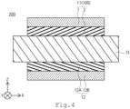
- FIG. 4 shows a schematic diagram of an embodiment of a membrane electrode assembly 200.
- the membrane electrode assembly 200 has a first electrode 11, a second electrode 12, and an electrolyte membrane 13.
- the first electrode 11 is preferably an anode electrode and the second electrode 12 is preferably a cathode electrode. It is preferred to use the electrode 100 of the first embodiment for the first electrode 11.
- the membrane electrode assembly 200 of the embodiment is preferably used in an electrochemical cell or stack for hydrogen generation or oxygen generation.
- electrode 100 of the first embodiment be used as the first electrode 11.
- the catalyst layer 2 of the electrode 100 used as the first electrode 11 is provided on the electrolyte membrane 13 side. It is preferable that the catalyst layer 2 is in direct contact with the electrolyte membrane 13.
- the second electrode 12 has a second support 12A and a second catalyst layer 12B.
- the second catalyst layer 12B is provided on the second support 12A.
- the second catalyst layer 12B is provided on the electrolyte membrane 13 side. It is preferable that the second catalyst layer 12B is in direct contact with the electrolyte membrane 13.
- the second support 12A is a porous material through which gases and liquids pass.
- the second support 12A is, for example, carbon paper or a metal mesh.
- a porous support of valve metal is preferable.
- the porous support of valve metal is a porous support material including one or more metals selected from the group consisting of titanium, aluminum, tantalum, niobium, hafnium, zirconium, zinc, tungsten, bismuth, and antimony, and a porous support material including one or more metals selected from the group consisting of titanium, aluminum, tantalum, niobium, hafnium, zirconium, zinc, tungsten, bismuth and antimony.
- the second support 12A has a carbon layer (MPL layer) containing carbon particles and a water repellent resin (fluororesin such as PTFE or Nafion). The carbon layer is provided, for example, between the carbon paper and the second catalyst layer 12B.
- the second catalyst layer 12B has a catalyst metal. It is preferable that the second catalyst layer 12B is particles of catalyst metal and that the catalyst metal is not supported on a carrier.
- the second catalyst layer 12B is preferably a porous catalyst layer.
- the catalyst metal is not limited, but includes, for example, one or more metal elements selected from the group consisting of Pt, Rh, Os, Ir, Pd, and Au. It is preferable that one or more metal elements selected from the group consisting of such catalytic materials be included.
- the catalyst metal is preferably metal, alloy, or metal oxide.
- the second catalyst layer 12B for example, preferably has a plurality of catalyst units consisting of alternately stacked catalyst layers in sheet form and gap layers.
- the amount of metal per area of the second catalyst layer 12B is preferably 0.02 [mg/cm 2 ] or more and 1.0 [mg/cm 2 ] or less, and more preferably 0.05 [mg/cm 2 ] or more and 0.5 [mg/cm 2 ] or less.
- the sum of these masses can be measured by ICP-MS.
- the porosity of the second catalyst layer 12B is preferably 10 [%] or more and 90 [%] or less, and more preferably 30 [%] or more and 70 [%] or less.
- the electrolyte membrane 13 is a proton-conducting membrane. Fluorinated polymers or aromatic hydrocarbon polymers having one or more selected from the group consisting of sulfonic acid groups, sulfonimide groups, and sulfate groups are preferred as the electrolyte membrane 13.
- the fluorinated polymers having sulfonic acid groups are preferred as electrolyte membranes 13.
- Nafion trademark DuPont
- Flemion trademark Asahi Kasei
- Selemion trademark Asahi Kasei
- Aquivion trademark Solvay Specialty Polymers
- Aciplex trademark Asahi Glass
- the thickness of the electrolyte membrane 13 can be determined appropriately in consideration of the membrane's permeability, durability, and other characteristics. From the viewpoint of strength, dissolution resistance, and output power characteristics of the MEA, the thickness of the electrolyte membrane 13 is preferably 20 [pm] or more and 500 [pm] or less, more preferably 50 [um] or more and 300 [pm] or less, and even more preferably 80 [pm] or more and 200 [pm] or less.
- the electrolyte membrane 13 preferably includes a noble metal region on the first electrode 11 side.
- the noble metal region includes noble metal particles.
- the noble metal region is preferably located on the surface of the electrolyte membrane 13.
- the noble metal region preferably consists of a single region, but may also consist of multiple separated regions.
- the noble metal particles are preferably particles of one or more noble metals selected from the group consisting of Pt, Re, Rh, Ir, Pd, and Ru.
- the noble metal particles may include particles of an alloy containing one or more selected from the group consisting of Pt, Re, Rh, Ir, Pd and Ru.
- the noble metal particles are preferably particles of one noble metal selected from the group consisting of Pt, Re, Rh, Ir, Pd, and Ru. Pt particles are preferred for the noble metal particles.
- Re particles are preferred for the noble metal particles.
- Rh particles are preferred for the noble metal particles.
- Ir particles are preferred for noble metal particles.
- Pd particles are preferred for noble metal particles.
- Ru particles are preferred for noble metal particles.
- the noble metal particles oxidize hydrogen that is generated on the cathode side and passes through the electrolyte membrane 13.
- the noble metal particles can reduce hydrogen leakage. Because the noble metal particles are present on the anode side, they are less likely to oxidize the hydrogen that is discharged from the cathode side.
- the area where noble metal particles are present may also be present in the electrolyte membrane 13 on the second electrode 12 (cathode) side.
- the average circumscribed circle diameter of the noble metal particles is preferably 0.5 [nm] or more and 50 [nm] or less, more preferably 1 [nm] or more and 10 [nm] or less, and even more preferably 1 [nm] or more and 5 [nm] or less.
- the membrane electrode assembly can be operated for a long time with high activity.
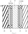
- FIG. 5 shows a cross-sectional diagram of the electrochemical cell 300 of the second embodiment.
- the electrochemical cell 300 is described below using water electrolysis as an example, but hydrogen can also be generated by decomposing ammonia and other substances in addition to water.
- the electrochemical cell 300 of the third embodiment has a first electrode (anode) 11, a second electrode (cathode) 12, an electrolyte membrane 13, a gasket 21, a gasket 22, a separator 23, and a separator 24.
- a gasket 21 the sealing member of the first electrode 11 may be used.
- the gasket 22 the seal member of the second electrode 12 may be used.
- the membrane electrode assembly 200 that the first electrode (anode) 11, the second electrode (cathode) 12, and the electrolyte membrane 13 are bonded together.
- the anode feeder may be provided separately from the separator 23.
- the cathode feeder may be provided separately from the separator 24.
- a power supply is connected to separators 23 and 24, and reactions occur at the anodes 11 and the cathodes 12.
- Water for example, is supplied to the anode 11, and at the anode 11, water is decomposed into protons, oxygen and electrons.
- the support and feeder of the electrode is a porous material, and this porous material acts as a passage plate. The produced and unreacted water is discharged, while the protons and electrons are used for cathodic reactions.
- protons and electrons react to produce hydrogen. Either or both of the hydrogen and oxygen produced are used, for example, as fuel for fuel cells.
- FIG. 6 is a schematic cross-sectional diagram of a stack 400 of the fourth embodiment.
- the stack 400 of the fourth embodiment shown in FIG. 6 includes a plurality of MEA 200 or electrochemical cells 300 connected in series, with tightening plates 31 and 32 attached to both ends of the MEA or electrochemical cells.
- the stack 400 consisting of multiple MEA 200 or multiple electrochemical cells 300 connected in series can produce a large amount of hydrogen.
- a fifth embodiment relates to an electrolyzer.
- FIG. 7 shows a conceptual diagram of the electrolyzer of the fifth embodiment.
- Electrolyzer 500 uses electrochemical cell 300 or stack 400.
- the electrolyzer of FIG. 7 is for water electrolysis.
- the electrolyzer for water electrolysis will be described.
- the electrodes of the embodiment can also be used in an electrolyzer that electrolyze carbon dioxide to produce organic substances such as methanol and ethylene, and carbon monoxide.
- single cells for water electrolysis are stacked in series to form a stack 400.
- the stack 400 is equipped with a power supply 41 and voltage is applied between the anode and cathode.
- a gas-liquid separator 42 that separates the generated gas and unreacted water, and a mixing tank 43 are connected.
- the water is circulated to the anodes.
- the oxygen produced at the anode passes through the gas-liquid separator 42 to obtain oxygen gas.
- a hydrogen purifier 49 is connected to the gas-liquid separator 48 to obtain high-purity hydrogen. Impurities are discharged through a path with a valve 50 connected to the hydrogen purifier 49.
- the stack and mixing tank can be heated to control stable operating temperatures, and the current density during pyrolysis can be controlled.
- a Ti non-woven fabric support with a size of 2 [cm] x 2 [cm] and a thickness of 200 [pm] is used as the support.
- Nickel and iridium are sputtered onto the titanium support to form the sheet layer precursor.
- only nickel is sputtered to form the gap layer precursor.
- This process of forming the sheet layer and gap layer is repeated 40 times to obtain a stacked structure with an Ir per area of 0.2 [mg/cm 2 ].
- the sputtering conditions for the sheet layer and gap layer are shown in Tables 1 and 2.
- the laminated catalyst is obtained with nickel partially dissolved by subsequent washing with sulfuric acid.
- the ratio of nickel in the laminated catalyst after acid treatment [wt%] to the metal elements in the catalyst metal is shown in Table 3.
- Example A the amount of residual nickel is controlled by varying the time of acid treatment. After acid treatment, the sheet layer precursor mostly becomes a sheet layer. After acid treatment, the gap layer precursor mostly becomes a gap layer.
- Sheet Layer Precursor Thickness [nm] Ir Ru Ni DC Output Power[W] Time [sec] DC Output Power[W] Time [sec] RF Output Power[W] Time [sec]
- the electrolyte membrane is 7[cm] x 7[cm] in size, Nafion115 manufactured by Chemours, and the electrolyte membrane is sandwiched between the anode and the cathode for hot pressing.
- the MEA is placed in a hot press apparatus and pressed at 130 [°C] and 20 [kg/cm 2 ] for 3 minutes, followed by press cooling at 25 [°C] and 20 [kg/cm 2 ] for 3 minutes.
- the resulting MEA and gasket are set between two separators with passage plate to create a PEEC single cell (electrochemical cell).
- a back pressure valve is attached to the outlet of the hydrogen side of the separator with flow paths to increase the internal pressure of hydrogen.
- Example A Comparative Example A
- Conditioning is performed on the single cell obtained for one day.
- the temperature is then maintained at 80 [°C] and ultrapure water is supplied to the anode at 0.01 [L/min].
- a current is applied between the anode and cathode at a current density of 2 [A/cm 2 ] using a power supply, and the cell voltage (VC) is measured after 48 hours of operation.
- the cell voltages (VC) are shown in Table 4.
- Durability is evaluated according to the following durability protocol.
- a single cell is maintained at 80 [°C] while ultrapure water is supplied to the anode at a flow rate of 0.01 [L/min].
- the cell voltage is held at 1.2 [V] for 3 seconds, and then held at 2.0 [V] for 3 seconds, making one cycle. This cycle is repeated for a total of 3,000 cycles.
- the cell voltage (V1) is then measured after 24 hours of operation with a current applied at a current density of 2 [A/cm 2 ] between the anode and the cathode using the power supply.
- the voltage rise rate (100 x (V1)/VC-100) is calculated by comparing the cell voltage (V1) with the cell voltage (VC) before durability evaluation.
- the voltage rise rate and cell voltage (V1) are shown in Table 2.
- Comparative Example A-2 with a low nickel content and a further collapsed gap layer, has a rather poor initial performance. On the other hand, the collapsed structure provides good durability, but the performance is inadequate because sufficient initial efficiency cannot be obtained with this structure. Comparative Example A-4, which has a large amount of nickel and wide gaps, has high initial performance, but the durability is not sufficient. This is considered to be because the structure has changed due to the dissolution of nickel during electrolysis. In Example A-2, a catalyst layer with relatively good initial performance and very high durability is obtained. The amount of nickel is 6.3%, and the gap layer is 8 [nm] wide, so the appropriate pore structure is maintained, and the initial performance and durability are considered to have been maintained.
- Example B includes examples in which nickel is also sputtered during the formation of the sheet layer precursor.
- Example B also includes examples in which iridium and/or ruthenium are also sputtered during the formation of the gap layer precursor. Except for the anode preparation conditions, Example B is the same as Example A-1, where single cells are prepared in the same way as in Example A-1. Table 7 also shows the amount of nickel after acid treatment.
- Example B-1 The prepared single cell is operated in the same manner as in Example A, and the cell voltage (VC) and cell voltage (V1) are obtained.
- the cell voltage (VC), the voltage rise rate, and cell voltage (V1) of Example B are shown in Table 8.
- Table 8 Cel Voltage [VC] Voltage Rise Rate [%] Cell Voltage [V1]
- Example B-1 1.73 1.16 1.75
- Example B-2 1.74 1.15 1.76
- Example B-3 1.75 1.14 1.77
- Example B-4 1.77 0.85 1.79 Comparative Example B-1 1.86 0.81 1.87 Comparative Example B-2 1.88 1.06 1.90 Comparative Example B-3 2.03 0.74 2.05 Comparative Example B-4 1.71 3.51 1.77
- Example B-2 which has a small amount of nickel and a collapsed gap layer, has a much worse initial performance. On the other hand, the structure is collapsed, so the durability is good, but this does not provide sufficient initial efficiency, so the performance is insufficient. Comparative Example B-4, which has a large amount of nickel and wide gaps, has high initial performance, but the durability is not sufficient. This is considered to be because the structure has changed due to the dissolution of nickel during electrolysis. In Example B-2, a catalyst layer with relatively good initial performance and very high durability is obtained. The amount of nickel is 6.2%, and the gap layer is wider (8 nm), so the appropriate pore structure is maintained, and the initial performance and durability are considered to have been maintained.
- Example C Anodes are prepared under the conditions shown in Tables 9 and 10.
- Example C one or more selected from the group consisting of nickel, cobalt, and manganese are sputtered during the formation of the gap layer precursor. Except for the anode preparation conditions, Example C is performed in the same manner as in Example A-1, where single cells are prepared in the same manner as in Example A-1. Table 11 also shows the amount of non-noble metals after acid treatment.
- the prepared single cell is operated in the same manner as in Example A, and the cell voltage (VC) and cell voltage (V1) are determined.
- the cell voltage (VC), the voltage rise rate, and cell voltage (V1) of Example C are shown in Table 12.
- the perforation effect is equivalent to that of Ni when not only Ni but also Co and Mn are added as perforating agents at the same time.
- the trends of initial performance and durability are the same as in Examples C-1 and C-2.
- Comparative Example C-2 in which the amount of perforating material is small and the gap layer is collapsed, shows considerably poor initial performance.
- the durability is good because the structure is collapsed, but the performance is insufficient because sufficient initial efficiency cannot be obtained in this case.
- Comparative Example C-4 which has a large amount of perforated material and a wide gap, has high initial performance, but the durability is not sufficient. This is thought to be due to structural changes caused by the dissolution of the porous material during electrolysis.
- Example C-2 a catalyst layer with relatively good initial performance and very high durability is obtained.
- the amount of porous material is 2.0% nickel, 2.5% Co, and 1.7% Mn, for a total of 6.2%, and the gap layer is 8 nm wide, which is thought to have maintained the appropriate pore structure, and thus the initial performance and durability are maintained.
- Example C-1 1.73 1.16 1.75
- Example C-2 1.74 1.15 1.76
- Example C-3 1.75 1.14 1.77
Landscapes
- Chemical & Material Sciences (AREA)
- Electrochemistry (AREA)
- Chemical Kinetics & Catalysis (AREA)
- Engineering & Computer Science (AREA)
- Organic Chemistry (AREA)
- Metallurgy (AREA)
- Materials Engineering (AREA)
- General Chemical & Material Sciences (AREA)
- Life Sciences & Earth Sciences (AREA)
- Sustainable Energy (AREA)
- Sustainable Development (AREA)
- Manufacturing & Machinery (AREA)
- Inorganic Chemistry (AREA)
- Electrolytic Production Of Non-Metals, Compounds, Apparatuses Therefor (AREA)
- Electrodes For Compound Or Non-Metal Manufacture (AREA)
- Catalysts (AREA)
- Laminated Bodies (AREA)
- Composite Materials (AREA)
Abstract
Description
- The present embodiments relate to an electrode, a membrane electrode assembly, an electrochemical cell, a stack, and an electrolyzer.
- In recent years, electrochemical cells have been actively studied. Among electrochemical cells, for example, a polymer electrolyte membrane electrolysis cell (PEMEC) is expected to be used for hydrogen generation in a large-scale energy storage system. In order to ensure sufficient durability and electrolytic properties, platinum (Pt) nanoparticle catalysts are generally used for PEMEC cathodes, and noble metal catalysts such as iridium (Ir) nanoparticle catalysts are used for positive electrodes. Additionally, a method for obtaining hydrogen from ammonia is also considered. Other applications include anodes for an electrolyzer that decompose carbon dioxide electrolytically to produce methanol, ethylene, and other organics, or carbon monoxide.
-
-
FIG. 1 is a schematic diagram of an electrode according to an embodiment. -
FIG. 2 is a cross-sectional schematic diagram of a catalyst layer according to an embodiment. -
FIG. 3 shows analysis spots according to an embodiment. -
FIG. 4 is a schematic diagram of a membrane electrode assembly according to an embodiment. -
FIG. 5 is a schematic diagram of an electrochemical cell according to an embodiment. -
FIG. 6 is a schematic diagram of a stack according to an embodiment. -
FIG. 7 is a conceptual diagram of an electrolyzer according to an embodiment. -
FIG. 8 is a graph of an example. - An electrode according to an embodiment includes a support, and a catalyst layer including a sheet layer and a gap layer stacked, alternately on the support. The catalyst layer includes noble oxide and non-noble oxide. 4 [wt%] or more and 8 [wt%] or less of metal elements included in the catalyst layer is non-noble metal. An average thickness of the gap layer is 6 [nm] or more and 50 [nm] or less .
- Hereinafter, the embodiments will be described with reference to the drawings.
- It is to be noted that the same reference numerals are given to common components throughout the embodiments, and redundant explanations are omitted.
- In the specification, values at 25 [°C] and 1 atm (atmosphere) are shown. Each thickness of the members represents an average of distance in a stacking direction.
- The first embodiment relates to an electrode.
FIG. 1 shows a schematic cross-sectional diagram of anelectrode 100 of the embodiment. Theelectrode 100 has asupport 1 and acatalyst layer 2. Thecatalyst layer 2 is used in the embodiment as a catalyst in the electrode reaction of water electrolysis. Thecatalyst layer 2 is also used as an anode catalyst in the electrolytic generation of ammonia. - The
electrode 100 of the first embodiment is used as an anode in water electrolysis. When thecatalyst layer 2 further contains a catalyst for fuel cells, theelectrode 100 of the embodiment is also used as the oxygen electrode of a fuel cell. Theelectrode 100 of the embodiment can also be used as an anode for electrolytic generation of ammonia. Theelectrode 100 of the embodiment can be used as an anode of an electrolyzer for ammonia synthesis. In addition to water electrolysis, for example, ultrapure water is supplied to the anode, water is decomposed to generate protons and oxygen at the anode, the generated protons pass through the electrolyte membrane, and nitrogen, protons, and electrons supplied to the cathode are bonded to produce ammonia. Theelectrode 100 of the embodiment can be used for the anode of a membrane electrode assembly used in electrolysis for ammonia synthesis. Theelectrode 100 of the embodiment can also be used as a cathode for generating hydrogen by electrolyzing ammonia. Theelectrode 100 according to embodiments can be used as a cathode for a hydrogen generation apparatus. Hereinafter, an example of water electrolysis is described in the first embodiment and the other embodiments. Theelectrode 100 according to embodiments can be also used for other than water electrolysis, for example, as a cathode of a membrane electrode assembly for electrolysis of decomposing ammonia so that ammonia is supplied to a cathode, proton and nitrogen is generated in the cathode by decomposing ammonia, the generated proton passes through an electrolyte membrane, and hydrogen is synthesized by binging protons and electrons. - It is preferable that a porous and highly conductive material be used as the
support 1. Thesupport 1 is a porous material through which gases and liquids pass. Since theelectrode 100 is also used as an anode in a water electrolysis cell, for example, a porous support of valve metal is preferred. It is preferable that the porous support of the valve metal is a porous support including one or more metals selected from the group consisting of titanium, aluminum, tantalum, niobium, hafnium, zirconium, zinc, tungsten, bismuth, and antimony, or a porous support including one metal selected from the group consisting of titanium, aluminum, tantalum, niobium, hafnium, zirconium, zinc, tungsten, bismuth, and antimony. - Ti is preferred as a durable valve metal for the
support 1. For example, Ti mesh, a cloth made of Ti fibers, or a Ti sintered body is used as thesupport 1. The porosity of thesupport 1 is preferably 20 [%] or more and 95 [%] or less, and more preferably 40 [%] or more and 90 [%] or less, considering the movement of materials. For example, when thesupport 1 is a metallic nonwoven fabric made of intertwined metallic fibers, the fiber diameter is preferably 1 [um] or more and 500 [pm] or less, and more preferably 1 [um] or more and 100 [pm] or less, considering the reactivity and the power-feeding property. When thesupport 1 is a particle sintered body, the particle diameter is 1 [um] or more and 500 [pm] or less, and more preferably 1 [um] or more and 100 [um] or less in consideration of reactivity and power-feeding property. - A coating layer can be added on the
support 1. The dense coating layer having conductivity improves the durability of theelectrode 100. The coating layer is not limited, but can be made of metallic materials, ceramic materials such as oxides and nitrides, and carbon. With respect to the coating layer, a multilayer or gradient structure composed of different materials can be formed to further enhance durability. - The
catalyst layer 2 includes noble metal oxides and non-noble metal oxides with Ir and Ru as main components. An intermediate layer, not shown, may be provided between thecatalyst layer 2 and thesupport 1. - The amount of noble metal in
catalyst layer 2 is preferably 0.02 [mg/cm2] or more and 1.0 [mg/cm2] or less, and more preferably 0.05 [mg/cm2] or more and 0.5 [mg/cm2] or less. The sum of these masses can be measured by ICP-MS. - The porosity of the
catalyst layer 2 is preferably 10 [%] or more and 90 [%] or less, and more preferably 30 [%] or more and 70 [%] or less. - The
catalyst layer 2 has a structure of alternately stacked thesheet layer 2A and thegap layer 2B. The stacking structure of thecatalyst layer 2 is shown in the schematic cross-sectional diagram of thecatalyst layer 2 inFIG. 2 . Thesheet layer 2A andgap layer 2B are stacked in parallel. Thegap layer 2B is mostly hollow, but some of thesheet layer 2A protrudes and thesheet layers 2A are connected. Thesheet layers 2A are connected bycolumnar member 2C present in thegap layer 2B, and the laminated structure is maintained. - The
sheet layer 2A is a sheet-like layer of agglomerated catalyst particles. There are some voids in thesheet layer 2A. Thegap layer 2B is the area between thesheet layer 2A. Unlike thesheet layer 2A, thegap layer 2B does not have a regular structure of catalyst particles. - The average thickness of one layer of the
sheet layer 2A is preferably 6 [nm] or more and 50 [nm] or less. The average thickness of one layer of thegap layer 2B is preferably 6 [nm] or more and 50 [nm] or less. The average thickness of one layer of thesheet layer 2A is preferably thicker than the average thickness of one layer of thegap layer 2B. Some gap layers 2B may be thicker than somesheet layers 2A. - The
catalyst layer 2 preferably includes an oxide including Ir and/or Ru. Thecatalyst layer 2 preferably includes Ir oxide or/and Ir and Ru composite oxide as the noble metal oxide, and optionally includes Ru oxide as the noble metal oxide. The sum of the concentrations of Ir and Ru among the noble metals incatalyst layer 2 is preferably 90 [wt%] or more and 100 [wt%] or less. - The
catalyst layer 2 preferably includes an oxide including one or more non-noble metal elements selected from the group consisting of Ni, Co, and Mn as non-noble metal oxides. The non-noble metals included incatalyst layer 2 preferably include Ni and, optionally, Co or/and Mn. When the amount of non-noble metal elements included incatalyst layer 2 is 100 [wt%], the total ratio of Ni, Co and Mn among the non-noble metals included incatalyst layer 2 is preferably 80 [wt%] or more and 100 [wt%] or less. - When the amount of all metal elements in the
catalyst layer 2 is 100 [wt%], 4 [wt%] or more and 8 [wt%] or less of the metal elements in thecatalyst layer 2 is preferably non-noble metals (the mass ratio of non-noble metal elements in the metal elements in thecatalyst layer 2 is 4 [wt%] or more and 8 [wt%] or less). When the amount of all metal elements in thecatalyst layer 2 is 100 [wt%], it is preferable that 4 [wt%] or more and 8 [wt%] or less of the metal elements in thecatalyst layer 2 is non-noble metal (the mass ratio of non-noble metal elements in the metal elements in thecatalyst layer 2 is 4 [wt%] or more and 8 [wt%] or less). The total concentration of one or more non-noble metals selected from the group consisting of Ni, Co, and Mn in the metal elements included in thecatalyst layer 2 is preferably 4 [wt%] or more and 8 [wt%] or less. When the amount of all metal elements in thecatalyst layer 2 is 100 [wt%], the ratio of Ni to the non-noble metal elements in thecatalyst layer 2 is preferably 50 [wt%] or more and 100 [wt%] or less, more preferably 75 [wt%] or more and 100 [wt%] or less. Non-noble metal elements are also present in thecatalyst layer 2 as oxides, acting as a co-catalyst for the noble metal oxides and structurally supporting thecatalyst layer 2. - When 4 [wt%] or more 8 [wt%] or less of the metal elements in the
catalyst layer 2 with the stacked structure of the embodiment are non-noble metals, the initial electrolytic voltage is high, but the voltage rise is preferably small when the MEA is allowed to run for a long time. Longer operation of MEAs is becoming possible, and the importance of small voltage rise is increasing in consideration of long operation time. When 10 [wt%] or more of the metal elements in thecatalyst layer 2 with the stacked structure of the embodiment is non-noble metal, the initial electrolytic voltage is kept low due to their catalyst effect. However, the electrolytic voltage tends to increase comparatively due to changes in the stacked structure of thecatalyst layer 2 as a result of elution of non-noble metal oxides during electrolytic operation. If less than 4% of the metal elements in thecatalyst layer 2 having the stacked structure of the embodiment is non-noble metal, it is difficult to maintain the stacked structure of thecatalyst layer 2, and thegap layer 2B becomes narrower because a lot ofsheet layers 2A may touch each other. When thegap layer 2B narrows, it becomes difficult for water and other substances to move within thecatalyst layer 2. If less than 4 [wt%] of the metal elements in thecatalyst layer 2 having the stacked structure of the embodiment is non-noble metal, the co-catalyst effect is small and the cell voltage of water electrolysis is high from the initial stage. - When the average thickness of the
gap layer 2B is 5 [nm] or less, thegap layer 2B is easily collapsed and the initial voltage is easily increased, although the structure of thesheet layer 2A can be maintained when the ratio of non-noble metal is 4 [wt%] or more and 8 [wt%] or less. When the average thickness of thegap layer 2B is 5 [nm] or less, the initial voltage is high when the non-noble metal ratio is 4 [wt%] or more and 8 [wt%] or less, but the voltage increase is small even after long-term operation. When the average thickness of thegap layer 2B is 6 [nm] or more and 50 [nm] or less, the structure of thesheet layer 2A and thegap layer 2B is maintained after a long period of operation when the non-noble metal ratio is 4 [wt%] or more and 8 [wt%] or less, and the water electrolysis voltage is maintained low because the structure of thegap layer 2B is not easily collapsed from the beginning. When the non-noble metal ratio is low and the average thickness of thegap layer 2B is thin, there are many areas where thegap layer 2B is collapsed due to thin or fewcolumnar bodies 2C, i.e., when the cross section of thecatalyst layer 2 is observed at the analyzed spots A1 to A9 inFIG. 3 , the areas where thegap layer 2B is less than 2 [nm] thick are occupies 20 [%] or more in the width and depth directions. - Each spot is square-shaped and has an area of at least 1 mm2. As shown in
FIG. 3 , when the length of theelectrode 100 is D1 and the width of theelectrode 100 is D2 (D1 ≥ D2), a virtual line is drawn at a distance of D3 (= D1/10) inward from each of the two opposing sides of theelectrode 100 in the width direction, a virtual line is drawn at a distance of D4 (= D2/10) from the two opposing sides in the length direction of theelectrode 100, and then draw a virtual line parallel to the width direction through the center of theelectrode 100 and a virtual line parallel to the length direction through the center of theelectrode 100. The area centered at the nine intersection points of the virtual lines is designated as analysis spots A1 to A9. The cross-section observed by SEM is perpendicular to the plane ofFIG. 3 and parallel to the width direction. The thickness of eachgap layer 2B in the analyzed spots A1 to A9 is obtained at intervals of 50 [nm] in the width direction of the SEM image. Then, determine the ratio of thegap layer 2B having a thickness of less than 2 [nm]. The average thicknesses of thegap layer 2B andsheet layer 2A are obtained in the same manner. - When the ratio of non-noble metals is, for example, 10 [wt%] or more, the catalyst structure is well maintained initially both when the thickness of the
gap layer 2B is 5 [nm] or less and when it is 6 [nm] or more. However, after long-term operation, it becomes difficult to maintain the catalytic structure due to the elution of more non-noble metals, and the cell voltage of water electrolysis tends to increase. - The inventors' research revealed that a high ratio of non-noble metals is preferable regardless of the thickness of the
gap layer 2B when considering the co-catalyst effect, and a low ratio of non-noble metals is preferable when considering the maintenance of the catalyst structure. Considering the effect of the catalyst itself and the effect of maintaining the catalyst structure itself, an intermediate non-noble metal ratio is expected to be preferable regardless of the thickness of thegap layer 2B, but as explained above, the thickness of thegap layer 2B is also relevant to obtain the two effects. From the viewpoint of obtaining both the effect of the co-catalyst and the maintenance of the catalyst structure, the thickness of thegap layer 2B is preferably 6 [nm] or more and 50 [nm] or less, and more preferably 6 [nm] or more and 10 [nm] or less when the non-noble metal ratio is 4 [wt%] or more and 8 [wt%] or less. - From the above viewpoint, it is preferable that 4 [wt%] or more and 7 [wt%] or less of the metal elements in the
catalyst layer 2 is non-noble metal and that the thickness of thegap layer 2B is 6 [nm] or more and 50 [nm] or less. The total concentration of one or more non-noble metals selected from the group consisting of Ni, Co, and Mn included in thecatalyst layer 2 to the metal elements included in thecatalyst layer 2 is preferably 4 [wt%] or more and 6 [wt%] or less, and the thickness of thegap layer 2B is 6 [nm] or more and 50 [nm] or less. The ratio of Ni to the non-noble metal elements in thecatalyst layer 2 is preferably 50 % or more and 100 % or less, and more preferably 75 % or more and 100 % or less. - From the above viewpoint, it is preferable that 4 [wt%] or more and 7 [wt%] or less of the metal elements in the
catalyst layer 2 is non-noble metal and that the thickness of thegap layer 2B is 6 [nm] or more and 30 [nm] or less. The total concentration of one or more non-noble metals selected from the group consisting of Ni, Co, and Mn in the metal elements included in thecatalyst layer 2 is preferably 4 [wt%] or more and 6 [wt%] or less. When the total amount of non-noble metals contained in thecatalyst layer 2 is 100 [wt%], the ratio of Ni to the non-noble metal elements is preferably 50 [wt%] or more and 100 [wt%] or less, and more preferably 75 [wt%] or more and 100 [wt%] or less. - The
catalyst layer 2 is preferably formed on thesupport 1 by sputtering alternately a sheet layer precursor that is substantially a precursor of thesheet layer 2A and contains noble metal oxides and a gap layer precursor that is substantially a precursor of thegap layer 2B and mainly composed of non-noble metal oxides and dissolving the non-noble metal oxides by acid treatment. When noble metals are also sputtered simultaneously during the formation of the gap layer precursors, [target output] x [output time] of noble metals is preferably 5% or more and 30% or less of [target output power] x [output time] of non-noble metals. If the gap layer precursor contains a large amount of noble metal oxides, Ni in the gap layer tends to remain dissolved during acid treatment, and the Ni ratio in the gap layer tends to increase. Since much of the Ni remaining in the gap layer is eluted at the potential when electrochemically generating oxygen, the remained non-noble metal oxide may be deposited on the electrolyte membrane and performance deteriorates after long-term operation. On the other hand, too little iridium in the gap layer causes the structure to collapse and the thickness of the gap layer to become thin, resulting in a high initial voltage due to the lack of smooth mass transport in the gap layer. - The concentration of each metal element in the
catalyst layer 2 can be determined by ICP-MS (inductively coupled plasma mass spectrometry). The concentration of each metal element in thecatalyst layer 2 is determined from after theelectrode 100 is manufactured until after the MEA or electrochemical cell is manufactured using the manufactured electrode and before voltage is applied externally. - The amount of non-noble metals (non-noble metal oxides) in the
catalyst layer 2 can be adjusted by adjusting the time of acid treatment and other conditions. - A second embodiment relates to a membrane electrode assembly (MEA).
FIG. 4 shows a schematic diagram of an embodiment of amembrane electrode assembly 200. Themembrane electrode assembly 200 has afirst electrode 11, asecond electrode 12, and anelectrolyte membrane 13. Thefirst electrode 11 is preferably an anode electrode and thesecond electrode 12 is preferably a cathode electrode. It is preferred to use theelectrode 100 of the first embodiment for thefirst electrode 11. Themembrane electrode assembly 200 of the embodiment is preferably used in an electrochemical cell or stack for hydrogen generation or oxygen generation. - It is preferable that
electrode 100 of the first embodiment be used as thefirst electrode 11. Thecatalyst layer 2 of theelectrode 100 used as thefirst electrode 11 is provided on theelectrolyte membrane 13 side. It is preferable that thecatalyst layer 2 is in direct contact with theelectrolyte membrane 13. - The
second electrode 12 has asecond support 12A and asecond catalyst layer 12B. Thesecond catalyst layer 12B is provided on thesecond support 12A. Thesecond catalyst layer 12B is provided on theelectrolyte membrane 13 side. It is preferable that thesecond catalyst layer 12B is in direct contact with theelectrolyte membrane 13. - It is preferable that a porous and highly conductive material is used as the
second support 12A. Thesecond support 12A is a porous material through which gases and liquids pass. Thesecond support 12A is, for example, carbon paper or a metal mesh. As a metal mesh, a porous support of valve metal is preferable. It is preferable that the porous support of valve metal is a porous support material including one or more metals selected from the group consisting of titanium, aluminum, tantalum, niobium, hafnium, zirconium, zinc, tungsten, bismuth, and antimony, and a porous support material including one or more metals selected from the group consisting of titanium, aluminum, tantalum, niobium, hafnium, zirconium, zinc, tungsten, bismuth and antimony. Thesecond support 12A has a carbon layer (MPL layer) containing carbon particles and a water repellent resin (fluororesin such as PTFE or Nafion). The carbon layer is provided, for example, between the carbon paper and thesecond catalyst layer 12B. - The
second catalyst layer 12B has a catalyst metal. It is preferable that thesecond catalyst layer 12B is particles of catalyst metal and that the catalyst metal is not supported on a carrier. Thesecond catalyst layer 12B is preferably a porous catalyst layer. The catalyst metal is not limited, but includes, for example, one or more metal elements selected from the group consisting of Pt, Rh, Os, Ir, Pd, and Au. It is preferable that one or more metal elements selected from the group consisting of such catalytic materials be included. The catalyst metal is preferably metal, alloy, or metal oxide. Thesecond catalyst layer 12B, for example, preferably has a plurality of catalyst units consisting of alternately stacked catalyst layers in sheet form and gap layers. - The amount of metal per area of the
second catalyst layer 12B is preferably 0.02 [mg/cm2] or more and 1.0 [mg/cm2] or less, and more preferably 0.05 [mg/cm2] or more and 0.5 [mg/cm2] or less. The sum of these masses can be measured by ICP-MS. - The porosity of the
second catalyst layer 12B is preferably 10 [%] or more and 90 [%] or less, and more preferably 30 [%] or more and 70 [%] or less. - The
electrolyte membrane 13 is a proton-conducting membrane. Fluorinated polymers or aromatic hydrocarbon polymers having one or more selected from the group consisting of sulfonic acid groups, sulfonimide groups, and sulfate groups are preferred as theelectrolyte membrane 13. The fluorinated polymers having sulfonic acid groups are preferred aselectrolyte membranes 13. For example, Nafion (trademark DuPont), Flemion (trademark Asahi Kasei), Selemion (trademark Asahi Kasei), Aquivion (trademark Solvay Specialty Polymers) or Aciplex (trademark Asahi Glass), etc. can be used as fluorinated polymers having sulfonic acid groups. - The thickness of the
electrolyte membrane 13 can be determined appropriately in consideration of the membrane's permeability, durability, and other characteristics. From the viewpoint of strength, dissolution resistance, and output power characteristics of the MEA, the thickness of theelectrolyte membrane 13 is preferably 20 [pm] or more and 500 [pm] or less, more preferably 50 [um] or more and 300 [pm] or less, and even more preferably 80 [pm] or more and 200 [pm] or less. - The
electrolyte membrane 13 preferably includes a noble metal region on thefirst electrode 11 side. The noble metal region includes noble metal particles. The noble metal region is preferably located on the surface of theelectrolyte membrane 13. The noble metal region preferably consists of a single region, but may also consist of multiple separated regions. - The noble metal particles are preferably particles of one or more noble metals selected from the group consisting of Pt, Re, Rh, Ir, Pd, and Ru. The noble metal particles may include particles of an alloy containing one or more selected from the group consisting of Pt, Re, Rh, Ir, Pd and Ru. The noble metal particles are preferably particles of one noble metal selected from the group consisting of Pt, Re, Rh, Ir, Pd, and Ru. Pt particles are preferred for the noble metal particles. Re particles are preferred for the noble metal particles. Rh particles are preferred for the noble metal particles. Ir particles are preferred for noble metal particles. Pd particles are preferred for noble metal particles. Ru particles are preferred for noble metal particles.
- The noble metal particles oxidize hydrogen that is generated on the cathode side and passes through the
electrolyte membrane 13. The noble metal particles can reduce hydrogen leakage. Because the noble metal particles are present on the anode side, they are less likely to oxidize the hydrogen that is discharged from the cathode side. The area where noble metal particles are present may also be present in theelectrolyte membrane 13 on the second electrode 12 (cathode) side. - The average circumscribed circle diameter of the noble metal particles is preferably 0.5 [nm] or more and 50 [nm] or less, more preferably 1 [nm] or more and 10 [nm] or less, and even more preferably 1 [nm] or more and 5 [nm] or less.
- By virtue of using the highly
durable electrode 100 as the anode of themembrane electrode assembly 200, the membrane electrode assembly can be operated for a long time with high activity. - A third embodiment relates to an electrochemical cell.
FIG. 5 shows a cross-sectional diagram of theelectrochemical cell 300 of the second embodiment. Theelectrochemical cell 300 is described below using water electrolysis as an example, but hydrogen can also be generated by decomposing ammonia and other substances in addition to water. - As shown in
FIG. 5 , theelectrochemical cell 300 of the third embodiment has a first electrode (anode) 11, a second electrode (cathode) 12, anelectrolyte membrane 13, agasket 21, agasket 22, aseparator 23, and aseparator 24. As thegasket 21, the sealing member of thefirst electrode 11 may be used. As thegasket 22, the seal member of thesecond electrode 12 may be used. - It is preferable that the
membrane electrode assembly 200 that the first electrode (anode) 11, the second electrode (cathode) 12, and theelectrolyte membrane 13 are bonded together. The anode feeder may be provided separately from theseparator 23. The cathode feeder may be provided separately from theseparator 24. - In the
electrochemical cell 300 shown inFIG. 5 , a power supply, not shown, is connected toseparators anodes 11 and thecathodes 12. Water, for example, is supplied to theanode 11, and at theanode 11, water is decomposed into protons, oxygen and electrons. The support and feeder of the electrode is a porous material, and this porous material acts as a passage plate. The produced and unreacted water is discharged, while the protons and electrons are used for cathodic reactions. In the cathode reaction, protons and electrons react to produce hydrogen. Either or both of the hydrogen and oxygen produced are used, for example, as fuel for fuel cells. - A fourth embodiment relates to a stack.
FIG. 6 is a schematic cross-sectional diagram of astack 400 of the fourth embodiment. Thestack 400 of the fourth embodiment shown inFIG. 6 includes a plurality ofMEA 200 orelectrochemical cells 300 connected in series, with tighteningplates - Since the amount of hydrogen produced by the
electrochemical cell 300 consisting of asingle MEA 200 is small, thestack 400 consisting ofmultiple MEA 200 or multipleelectrochemical cells 300 connected in series can produce a large amount of hydrogen. - A fifth embodiment relates to an electrolyzer.
FIG. 7 shows a conceptual diagram of the electrolyzer of the fifth embodiment.Electrolyzer 500 useselectrochemical cell 300 orstack 400. The electrolyzer ofFIG. 7 is for water electrolysis. The electrolyzer for water electrolysis will be described. For example, in the case of hydrogen generation from ammonia, it is preferable to employ a different configuration ofelectrodes 100. The electrodes of the embodiment can also be used in an electrolyzer that electrolyze carbon dioxide to produce organic substances such as methanol and ethylene, and carbon monoxide. - As shown in
FIG. 7 , single cells for water electrolysis are stacked in series to form astack 400. Thestack 400 is equipped with apower supply 41 and voltage is applied between the anode and cathode. On the anode side of thestack 400, a gas-liquid separator 42 that separates the generated gas and unreacted water, and amixing tank 43 are connected. The water is circulated to the anodes. The oxygen produced at the anode passes through the gas-liquid separator 42 to obtain oxygen gas. On the cathode side, ahydrogen purifier 49 is connected to the gas-liquid separator 48 to obtain high-purity hydrogen. Impurities are discharged through a path with avalve 50 connected to thehydrogen purifier 49. The stack and mixing tank can be heated to control stable operating temperatures, and the current density during pyrolysis can be controlled. - Hereinafter, examples of the embodiments will be described.
- A Ti non-woven fabric support with a size of 2 [cm] x 2 [cm] and a thickness of 200 [pm] is used as the support. Nickel and iridium are sputtered onto the titanium support to form the sheet layer precursor. Then, only nickel is sputtered to form the gap layer precursor. This process of forming the sheet layer and gap layer is repeated 40 times to obtain a stacked structure with an Ir per area of 0.2 [mg/cm2]. The sputtering conditions for the sheet layer and gap layer are shown in Tables 1 and 2. The laminated catalyst is obtained with nickel partially dissolved by subsequent washing with sulfuric acid. The ratio of nickel in the laminated catalyst after acid treatment [wt%] to the metal elements in the catalyst metal is shown in Table 3. In Example A, the amount of residual nickel is controlled by varying the time of acid treatment. After acid treatment, the sheet layer precursor mostly becomes a sheet layer. After acid treatment, the gap layer precursor mostly becomes a gap layer.
[Table 1] Sheet Layer Precursor Thickness [nm] Ir Ru Ni DC Output Power[W] Time [sec] DC Output Power[W] Time [sec] RF Output Power[W] Time [sec] Example A-1 20 50 360 0 0 370 360 Example A-2 20 50 360 0 0 370 360 Example A-3 20 50 360 0 0 370 360 Example A-4 20 50 360 0 0 370 360 Comparative Example A-1 20 50 360 0 0 370 360 Comparative Example A-2 20 50 360 0 0 370 360 Comparative Example A-3 20 50 360 0 0 370 360 Comparative Example A-4 20 50 360 0 0 370 360 [Table 2] Gap Layer Precursor Time of Acid Treatment [hrs] Thickness [nm] Ir Ru Ni DC Output Power[W] Time [sec] DC Output Power[W] Time [sec] RF Output Power[W] Time [sec] Example A-1 9 20 90 0 0 200 90 1 Example A-2 8 20 90 0 0 200 90 2 Example A-3 7 20 90 0 0 200 90 3 Example A-4 6 20 90 0 0 200 90 4 Comparative Example A-1 5 20 90 0 0 200 90 5 Comparative Example A-2 5 20 90 0 0 200 90 8 Comparative Example A-3 5 20 90 0 0 200 90 10 Comparative Example A-4 12 20 90 0 0 200 90 0.5 [Table 3] Amount of Ni [%] Example A-1 8.0 Example A-2 6.3 Example A-3 5.0 Example A-4 4.0 Comparative Example A-1 3.8 Comparative Example A-2 3.0 Comparative Example A-3 2.5 Comparative Example A-4 20.0 - Prepare carbon paper Toray 060 (Toray Industries, Inc.) with an MPL layer of size 2 [cm] x 2 [cm] and thickness 190 [um] as the support. On this support, a porous catalyst layer containing a plurality of catalyst units with a stacked structure including a void layer is formed by sputtering method so that the loading density of Pt catalyst is 0.1 [mg/cm2], and an electrode with a porous catalyst layer is obtained. This electrode is used as a standard cathode in the Examples and Comparative Examples.
- The electrolyte membrane is 7[cm] x 7[cm] in size, Nafion115 manufactured by Chemours, and the electrolyte membrane is sandwiched between the anode and the cathode for hot pressing. The MEA is placed in a hot press apparatus and pressed at 130 [°C] and 20 [kg/cm2] for 3 minutes, followed by press cooling at 25 [°C] and 20 [kg/cm2] for 3 minutes.
- The resulting MEA and gasket are set between two separators with passage plate to create a PEEC single cell (electrochemical cell). A back pressure valve is attached to the outlet of the hydrogen side of the separator with flow paths to increase the internal pressure of hydrogen.
- Next, the anodes of Example A and Comparative Example A are evaluated. Conditioning is performed on the single cell obtained for one day. The temperature is then maintained at 80 [°C] and ultrapure water is supplied to the anode at 0.01 [L/min]. A current is applied between the anode and cathode at a current density of 2 [A/cm2] using a power supply, and the cell voltage (VC) is measured after 48 hours of operation. The cell voltages (VC) are shown in Table 4.
- Initial voltage is evaluated according to cell voltage (VC) as follows.
- Cell voltage (VC) 1.7 [V] or more and less than 1.85 [V] Rating: A
- Cell voltage (VC) 1.85 [V] or more and less than 1.9 [V] Rating: B
- Cell voltage (VC) 1.9 [V] or more and 2.4 [V] or less Rating: C
- Durability is evaluated according to the following durability protocol. A single cell is maintained at 80 [°C] while ultrapure water is supplied to the anode at a flow rate of 0.01 [L/min]. Under these conditions, the cell voltage is held at 1.2 [V] for 3 seconds, and then held at 2.0 [V] for 3 seconds, making one cycle. This cycle is repeated for a total of 3,000 cycles. The cell voltage (V1) is then measured after 24 hours of operation with a current applied at a current density of 2 [A/cm2] between the anode and the cathode using the power supply. The voltage rise rate (100 x (V1)/VC-100) is calculated by comparing the cell voltage (V1) with the cell voltage (VC) before durability evaluation. The voltage rise rate and cell voltage (V1) are shown in Table 2.
- The durability is evaluated according to the voltage rise rate as follows.
- Voltage rise rate 0 [%] or more and 1.5 [%] or less: A
- Voltage rise rate 1.5[%] or more and 3[%] or less: B
- Voltage rise rate more than 3 [%] and less than 5 [%]: C
- Voltage rise rate more 5 [%] and 50 [%] or less: D
- Initial voltage is evaluated as follows according to cell voltage (V1).
- Cell voltage (V1) 1.7[V] or more and less than 1.85[V] Rating: A
- Cell voltage (V1) 1.85 [V] or more and less than 1.9 [V] Rating: B
- Cell voltage (V1) 1.9[V] or more and 2.4[V] or less Rating: C
- The graph in
FIG. 8 shows the relationship between cell voltage (V) and operating time for a single cell with a 3% nickel anode electrode (Comparative Example A-2: single point long chain line), a single cell with a 6.3% nickel anode electrode (Example A-2: solid line), and a single cell with an anode electrode including 20% Ni (Comparative Example A-4: dashed line) are shown in the graph below, representing the relationship between cell voltage (V) and operating time. - Comparative Example A-2, with a low nickel content and a further collapsed gap layer, has a rather poor initial performance. On the other hand, the collapsed structure provides good durability, but the performance is inadequate because sufficient initial efficiency cannot be obtained with this structure. Comparative Example A-4, which has a large amount of nickel and wide gaps, has high initial performance, but the durability is not sufficient. This is considered to be because the structure has changed due to the dissolution of nickel during electrolysis. In Example A-2, a catalyst layer with relatively good initial performance and very high durability is obtained. The amount of nickel is 6.3%, and the gap layer is 8 [nm] wide, so the appropriate pore structure is maintained, and the initial performance and durability are considered to have been maintained.
- Anodes are prepared under the conditions shown in Tables 5 and 6. Example B includes examples in which nickel is also sputtered during the formation of the sheet layer precursor. Example B also includes examples in which iridium and/or ruthenium are also sputtered during the formation of the gap layer precursor. Except for the anode preparation conditions, Example B is the same as Example A-1, where single cells are prepared in the same way as in Example A-1. Table 7 also shows the amount of nickel after acid treatment.
[Table 5] Sheet Layer Precursor Thickness [nm] Ir Ru Ni DC Output Power[W] Time [sec] DC Output Power[W] Time [sec] RF Output Power[W] Time [sec] Example B-1 20 25 360 25 360 370 360 Example B-2 20 25 360 25 360 370 360 Example B-3 20 25 360 25 360 370 360 Example B-4 20 25 360 25 360 370 360 Comparative Example B-1 20 25 360 25 360 370 360 Comparative Example B-2 20 25 360 25 360 370 360 Comparative Example B-3 20 25 360 25 360 370 360 Comparative Example B-4 20 25 360 25 360 370 360 [Table 6] Gap Layer Precursor Time of Acid Treatment [hrs] Thickness [nm] Ir Ru Ni DC Output Power[W] Time [sec] DC Output Power[W] Time [sec] RF Output Power[W] Time [sec] Example B-1 9 10 90 10 90 200 90 1 Example B-2 8 10 90 10 90 200 90 2 Example B-3 7 10 90 10 90 200 90 3 Example B-4 6 10 90 10 90 200 90 4 Comparative Example B-1 5 10 90 10 90 200 90 5 Comparative Example B-2 5 10 90 10 90 200 90 8 Comparative Example B-3 5 10 90 10 90 200 90 10 Comparative Example B-4 12 10 90 10 90 200 90 0.5 {Table 7] Amount of Ni [%] Example B-1 8.0 Example B-2 6.2 Example B-3 5.1 Example B-4 4.0 Comparative Example B-1 3.8 Comparative Example B-2 3.1 Comparative Example B-3 2.5 Comparative Example B-4 19.5 - The prepared single cell is operated in the same manner as in Example A, and the cell voltage (VC) and cell voltage (V1) are obtained. The cell voltage (VC), the voltage rise rate, and cell voltage (V1) of Example B are shown in Table 8.
[Table 8] Cel Voltage [VC] Voltage Rise Rate [%] Cell Voltage [V1] Example B-1 1.73 1.16 1.75 Example B-2 1.74 1.15 1.76 Example B-3 1.75 1.14 1.77 Example B-4 1.77 0.85 1.79 Comparative Example B-1 1.86 0.81 1.87 Comparative Example B-2 1.88 1.06 1.90 Comparative Example B-3 2.03 0.74 2.05 Comparative Example B-4 1.71 3.51 1.77 - The overall initial voltage is improved by adding Ru. This is due to Ru's excellent catalytic performance as water electrolysis. On the other hand, the durability of Ru is worse than that of Ir alone, indicating that Ru does not have high long-term durability. Despite these trends, the initial performance and durability trends are similar to those of Example A. Comparative Example B-2, which has a small amount of nickel and a collapsed gap layer, has a much worse initial performance. On the other hand, the structure is collapsed, so the durability is good, but this does not provide sufficient initial efficiency, so the performance is insufficient. Comparative Example B-4, which has a large amount of nickel and wide gaps, has high initial performance, but the durability is not sufficient. This is considered to be because the structure has changed due to the dissolution of nickel during electrolysis. In Example B-2, a catalyst layer with relatively good initial performance and very high durability is obtained. The amount of nickel is 6.2%, and the gap layer is wider (8 nm), so the appropriate pore structure is maintained, and the initial performance and durability are considered to have been maintained.
- Anodes are prepared under the conditions shown in Tables 9 and 10. In Example C, one or more selected from the group consisting of nickel, cobalt, and manganese are sputtered during the formation of the gap layer precursor. Except for the anode preparation conditions, Example C is performed in the same manner as in Example A-1, where single cells are prepared in the same manner as in Example A-1. Table 11 also shows the amount of non-noble metals after acid treatment.
[Table 9] Thickness [nm] Ir Ru Ni Co Mn DC Output Power[W] Time [sec] DC Output Power[W] Time [sec] RF Output Power[W] Time [sec] DC Output Power[W] Time [sec] RF Output Power[W] Time [sec] Example C-1 20 25 360 25 360 120 360 150 360 130 360 Example C-2 20 25 360 25 360 120 360 150 360 130 360 Example C-3 20 25 360 25 360 120 360 150 360 130 360 Example C-4 20 25 360 25 360 120 360 150 360 130 360 Comparative Example C-1 20 25 360 25 360 120 360 150 360 130 360 Comparative Example C-2 20 25 360 25 360 120 360 150 360 130 360 Comparative Example C-3 20 25 360 25 360 120 360 150 360 130 360 Comparative Example C-4 20 25 360 25 360 120 360 150 360 130 360 [Table 10] Gap Layer Precursor Time of Acid Treatment [hrs] Thickness [nm] Ir Ru Ni DC Output Power[W] Time [sec] DC Output Power[W] Time [sec] RF Output Power[W] Time [sec] Example C-1 9 10 90 10 90 10 90 1 Example C-2 8 10 90 10 90 10 90 2 Example C-3 7 10 90 10 90 10 90 3 Example C-4 6 10 90 10 90 10 90 4 Comparative Example C-1 5 10 90 10 90 10 90 5 Comparative Example C-2 5 10 90 10 90 10 90 8 Comparative Example C-3 5 10 90 10 90 10 90 10 Comparative Example C-4 12 10 90 10 90 10 90 0.5 [Table 11] Amount of Ni [%] Amount of Co [%] Amount of Mn [%] Example C-1 3.0 3.0 2.0 Example C-2 2.0 2.5 1.7 Example C-3 1.5 2.2 1.6 Example C-4 1.0 1.9 1.2 Comparative Example C-1 1.0 1.5 1.0 Comparative Example C-2 0.7 1.2 0.9 Comparative Example C-3 0.6 1.0 0.8 Comparative Example C-4 6.0 8.0 7.0 - The prepared single cell is operated in the same manner as in Example A, and the cell voltage (VC) and cell voltage (V1) are determined. The cell voltage (VC), the voltage rise rate, and cell voltage (V1) of Example C are shown in Table 12.
- The perforation effect is equivalent to that of Ni when not only Ni but also Co and Mn are added as perforating agents at the same time. In other words, the trends of initial performance and durability are the same as in Examples C-1 and C-2. Comparative Example C-2, in which the amount of perforating material is small and the gap layer is collapsed, shows considerably poor initial performance. On the other hand, the durability is good because the structure is collapsed, but the performance is insufficient because sufficient initial efficiency cannot be obtained in this case. Comparative Example C-4, which has a large amount of perforated material and a wide gap, has high initial performance, but the durability is not sufficient. This is thought to be due to structural changes caused by the dissolution of the porous material during electrolysis. In Example C-2, a catalyst layer with relatively good initial performance and very high durability is obtained. The amount of porous material is 2.0% nickel, 2.5% Co, and 1.7% Mn, for a total of 6.2%, and the gap layer is 8 nm wide, which is thought to have maintained the appropriate pore structure, and thus the initial performance and durability are maintained.
[Table 12] Cel Voltage [VC] Voltage Rise Rate [%] Cell Voltage [V1] Example C-1 1.73 1.16 1.75 Example C-2 1.74 1.15 1.76 Example C-3 1.75 1.14 1.77 Example C-4 1.78 1.12 1.80 Comparative Example C-1 1.86 1.08, 1.88 Comparative Example C-2 1.88 1.06 1.90 Comparative Example C-3 2.03 0.74 2.05 Comparative Example C-4 1.69 5.33 1.78 - Some elements are expressed only by element symbols thereof.
- Hereinafter, clauses of embodiments are additionally noted.
-
Clause 1. An electrode comprising:- a support; and
- a catalyst layer including a sheet layer and a gap layer stacked, alternately on the support, wherein
- the catalyst layer includes noble oxide and non-noble oxide,
- 4 [wt%] or more and 8 [wt%] or less of metal elements included in the catalyst layer is non-noble metal, and
- an average thickness of the gap layer is 6 [nm] or more and 50 [nm] or less.
-
Clause 2. The electrode according toclause 1, wherein- the non-noble metal oxide is an oxide including one or more metal elements selected from the group consisting of Ni, Co, and Mn. Clause 3. The electrode according to
clause - the non-noble metal oxide is an oxide including one or more metal elements selected from the group consisting of Ni, Co, and Mn, and
- the total ratio of Ni, Co and Mn among the non-noble metal elements included in catalyst layer is 80 [wt%] or more and 100 [wt%] or less.
- the non-noble metal oxide is an oxide including one or more metal elements selected from the group consisting of Ni, Co, and Mn. Clause 3. The electrode according to
- Clause 4. The electrode according to any one of
clauses 1 to 3, wherein
the noble oxide is an oxide including Ir and/or Ru. - Clause 5. The electrode according to any one of
clauses 1 to 4, wherein
4 [wt%] or more and 7 [wt%] or less of the metal elements in the catalyst layer is non-noble metal. - Clause 6. The electrode according to any one of
clauses 1 to 4, wherein
4 [wt%] or more and 6 [wt%] or less of the metal elements in the catalyst layer is non-noble metal. - Clause 7 A membrane electrolyte assembly comprising:
the electrode according to any one ofclauses 1 to 6. - Clause 8. An electrochemical cell comprising:
the membrane electrolyte assembly according to clause 7. - Clause 9. A stack comprising:
the membrane electrolyte assembly according to clause 7. -
Clause 10. A stack comprising:
the electrochemical cell according to clause 8. -
Clause 11. An electrolyzer comprising:
the stack according to clause 9. -
Clause 12. An electrolyzer comprising:
the stack according toclause 10. - While certain embodiments have been described, these embodiments have been presented by way of example only, and are not intended to limit the scope of the inventions. Indeed, the novel embodiments described herein, for example, PEMEC as a water electrolysis cell may be embodied in a variety of other forms; furthermore, various omissions, substitutions and changes in the form of the embodiments described herein may be made without departing from the spirit of the inventions. The accompanying claims and their equivalents are intended to cover such forms or modifications as would fall within the scope and spirit of the inventions.
| Cel Voltage [VC] | Voltage Rise Rate [%] | Cell Voltage [V1] | |
| Example A-1 | 1.80 | 0.56 | 1.81 |
| Example A-2 | 1.81 | 0.55 | 1.82 |
| Example A-3 | 1.82 | 0.44 | 1.83 |
| Example A-4 | 1.85 | 0.27 | 1.86 |
| Comparative Example A-1 | 1.90 | 0.26 | 1.91 |
| Comparative Example A-2 | 1.95 | 0.26 | 1.96 |
| Comparative Example A-3 | 2.10 | 0.24 | 2.11 |
| Comparative Example A-4 | 1.76 | 2.27 | 1.80 |
Claims (12)
- An electrode comprising:a support; anda catalyst layer including a sheet layer and a gap layer stacked, alternately on the support, whereinthe catalyst layer includes noble oxide and non-noble oxide,4 [wt%] or more and 8 [wt%] or less of metal elements included in the catalyst layer is non-noble metal, andan average thickness of the gap layer is 6 [nm] or more and 50 [nm] or less.
- The electrode according to claim 1, wherein
the non-noble metal oxide is an oxide including one or more metal elements selected from the group consisting of Ni, Co, and Mn. - The electrode according to claim 1 or 2, whereinthe non-noble metal oxide is an oxide including one or more metal elements selected from the group consisting of Ni, Co, and Mn, andthe total ratio of Ni, Co and Mn among the non-noble metal elements included in catalyst layer is 80 [wt%] or more and 100 [wt%] or less.
- The electrode according to any one of claims 1 to 3, wherein the noble oxide is an oxide including Ir and/or Ru.
- The electrode according to any one of claims 1 to 4, wherein
4 [wt%] or more and 7 [wt%] or less of the metal elements in the catalyst layer is non-noble metal. - The electrode according to any one of claims 1 to 4, wherein
4 [wt%] or more and 6 [wt%] or less of the metal elements in the catalyst layer is non-noble metal. - A membrane electrolyte assembly comprising:
the electrode according to any one of claims 1 to 6. - An electrochemical cell comprising:
the membrane electrolyte assembly according to claim 7. - A stack comprising:
the membrane electrolyte assembly according to claim 7. - A stack comprising:
the electrochemical cell according to claim 8. - An electrolyzer comprising:
the stack according to claim 9. - An electrolyzer comprising:
the stack according to claim 10.
Applications Claiming Priority (1)
| Application Number | Priority Date | Filing Date | Title |
|---|---|---|---|
| JP2022162625A JP2024055578A (en) | 2022-10-07 | 2022-10-07 | Electrodes, membrane electrode assemblies, electrochemical cells, stacks, electrolyzers |
Publications (2)
| Publication Number | Publication Date |
|---|---|
| EP4350045A2 true EP4350045A2 (en) | 2024-04-10 |
| EP4350045A3 EP4350045A3 (en) | 2024-10-30 |
Family
ID=87933833
Family Applications (1)
| Application Number | Title | Priority Date | Filing Date |
|---|---|---|---|
| EP23195661.6A Pending EP4350045A3 (en) | 2022-10-07 | 2023-09-06 | Electrode, membrane electrode assembly, electrochemical cell, stack, and electrolyzer |
Country Status (4)
| Country | Link |
|---|---|
| US (1) | US20240120499A1 (en) |
| EP (1) | EP4350045A3 (en) |
| JP (1) | JP2024055578A (en) |
| AU (1) | AU2023226691B2 (en) |
Family Cites Families (10)
| Publication number | Priority date | Publication date | Assignee | Title |
|---|---|---|---|---|
| JP4740179B2 (en) * | 2007-03-20 | 2011-08-03 | 株式会社東芝 | Catalyst layer-supporting substrate manufacturing method, membrane electrode composite manufacturing method, and fuel cell manufacturing method |
| JP5342824B2 (en) * | 2008-07-25 | 2013-11-13 | 株式会社東芝 | Method for producing catalyst layer-carrying substrate, catalyst layer-carrying substrate, membrane electrode assembly, and fuel cell |
| US10648092B2 (en) * | 2015-11-10 | 2020-05-12 | Kabushiki Kaisha Toshiba | Electrode, membrane electrode assembly, electrochemical cell, and stack |
| JP2017115232A (en) * | 2015-12-25 | 2017-06-29 | 株式会社東芝 | Electrode, membrane electrode composite, electrochemical cell and stack |
| EP3453785A1 (en) * | 2017-09-07 | 2019-03-13 | Kabushiki Kaisha Toshiba | Membrane electrode assembly, electrochemical cell, and electrochemical device |
| JP7003016B2 (en) * | 2018-03-22 | 2022-01-20 | 株式会社東芝 | Oxygen evolution catalyst, anode, membrane electrode composite, water electrolysis cell, stack and water electrolysis device used for the anode of water electrolysis |
| US11515552B2 (en) * | 2018-03-22 | 2022-11-29 | Kabushiki Kaisha Toshiba | Catalyst laminate, membrane electrode assembly, electrochemical cell, stack, water electrolyzer, and hydrogen utilizing system |
| US10777821B2 (en) * | 2018-03-22 | 2020-09-15 | Kabushiki Kaisha Toshiba | Catalyst, anode, membrane electrode assembly, water electrolysis cell, stack, water electrolyzer, and hydrogen utilizing system |
| JP6971944B2 (en) * | 2018-03-22 | 2021-11-24 | 株式会社東芝 | Catalyst laminates, membrane electrode composites, electrochemical cells, stacks, water electrolyzers and water utilization systems |
| JP7218263B2 (en) * | 2019-09-18 | 2023-02-06 | 株式会社東芝 | Laminated catalysts, electrodes, membrane electrode assemblies, electrochemical cells, stacks, fuel cells, reversible water electrolysis devices, vehicles and flying objects |
-
2022
- 2022-10-07 JP JP2022162625A patent/JP2024055578A/en active Pending
-
2023
- 2023-09-06 US US18/461,693 patent/US20240120499A1/en active Pending
- 2023-09-06 EP EP23195661.6A patent/EP4350045A3/en active Pending
- 2023-09-06 AU AU2023226691A patent/AU2023226691B2/en active Active
Also Published As
| Publication number | Publication date |
|---|---|
| AU2023226691A1 (en) | 2024-05-02 |
| AU2023226691B2 (en) | 2025-06-26 |
| EP4350045A3 (en) | 2024-10-30 |
| US20240120499A1 (en) | 2024-04-11 |
| JP2024055578A (en) | 2024-04-18 |
Similar Documents
| Publication | Publication Date | Title |
|---|---|---|
| EP3378970A1 (en) | Laminated electrolyte membrane, membrane electrode assembly, water electrolysis cell, stack and water electrolysis apparatus | |
| WO2018037774A1 (en) | Cathode, electrolysis cell for producing organic hydride, and organic hydride production method | |
| AU2023219977B2 (en) | Laminated catalyst, electrode, membrane electrode assembly, electrochemical cell, stack, and electrolyzer | |
| US20240110300A1 (en) | Electrode, membrane electrode assembly, electrochemical cell, stack, and electrolyzer | |
| EP4350040A2 (en) | Membrane electrode assembly, electrochemical cell, stack and electrolyzer | |
| EP4350045A2 (en) | Electrode, membrane electrode assembly, electrochemical cell, stack, and electrolyzer | |
| JP4868394B2 (en) | Gas diffusion electrode and manufacturing method thereof, and fuel cell and salt electrolysis cell using the gas diffusion electrode | |
| JP2024053540A (en) | Substrates, electrodes, membrane electrode assemblies, electrochemical cells, stacks, electrolysis equipment | |
| AU2023226658B2 (en) | Electrode, membrane electrode assembly, electrochemical cell, stack, and electrolyzer | |
| AU2024204846B2 (en) | Electrode, membrane electrode assembly, electrochemical cell, stack, and electrolyzer | |
| EP4431641A1 (en) | Electrode, membrane electrode assembly, electrochemical cell, stack, and electrolyzer | |
| EP4707431A1 (en) | Electrode | |
| EP4715090A1 (en) | Electrode, membrane electrode assembly, electrochemical cell, stack, and electrolyzer | |
| US20240133060A1 (en) | Electrode, membrane electrode assembly, electrochemical cell, stack, and electrolyzer | |
| JP2026056493A (en) | Substrate, electrode, membrane electrode assembly, electrochemical cell, stack, electrolytic device, and method for manufacturing the substrate | |
| CN118668230A (en) | Electrode, membrane electrode assembly, electrochemical cell, stack, and electrolytic device |
Legal Events
| Date | Code | Title | Description |
|---|---|---|---|
| PUAI | Public reference made under article 153(3) epc to a published international application that has entered the european phase |
Free format text: ORIGINAL CODE: 0009012 |
|
| STAA | Information on the status of an ep patent application or granted ep patent |
Free format text: STATUS: REQUEST FOR EXAMINATION WAS MADE |
|
| 17P | Request for examination filed |
Effective date: 20230906 |
|
| AK | Designated contracting states |
Kind code of ref document: A2 Designated state(s): AL AT BE BG CH CY CZ DE DK EE ES FI FR GB GR HR HU IE IS IT LI LT LU LV MC ME MK MT NL NO PL PT RO RS SE SI SK SM TR |
|
| PUAL | Search report despatched |
Free format text: ORIGINAL CODE: 0009013 |
|
| AK | Designated contracting states |
Kind code of ref document: A3 Designated state(s): AL AT BE BG CH CY CZ DE DK EE ES FI FR GB GR HR HU IE IS IT LI LT LU LV MC ME MK MT NL NO PL PT RO RS SE SI SK SM TR |
|
| RIC1 | Information provided on ipc code assigned before grant |
Ipc: C25B 15/08 20060101ALI20240920BHEP Ipc: C25B 11/093 20210101ALI20240920BHEP Ipc: C25B 11/053 20210101ALI20240920BHEP Ipc: C25B 1/04 20210101AFI20240920BHEP |
|
| STAA | Information on the status of an ep patent application or granted ep patent |
Free format text: STATUS: EXAMINATION IS IN PROGRESS |
|
| 17Q | First examination report despatched |
Effective date: 20250814 |
|
| RIC1 | Information provided on ipc code assigned before grant |
Ipc: C25B 1/04 20210101AFI20260210BHEP Ipc: C25B 11/053 20210101ALI20260210BHEP Ipc: C25B 11/093 20210101ALI20260210BHEP Ipc: C25B 15/08 20060101ALI20260210BHEP Ipc: C25B 1/02 20060101ALN20260210BHEP Ipc: C25B 1/27 20210101ALN20260210BHEP |