EP4349842A1 - Hydroxyaminophosphinic acid derivatives - Google Patents
Hydroxyaminophosphinic acid derivatives Download PDFInfo
- Publication number
- EP4349842A1 EP4349842A1 EP22199535.0A EP22199535A EP4349842A1 EP 4349842 A1 EP4349842 A1 EP 4349842A1 EP 22199535 A EP22199535 A EP 22199535A EP 4349842 A1 EP4349842 A1 EP 4349842A1
- Authority
- EP
- European Patent Office
- Prior art keywords
- atoms
- denotes
- differently
- identically
- denote
- Prior art date
- Legal status (The legal status is an assumption and is not a legal conclusion. Google has not performed a legal analysis and makes no representation as to the accuracy of the status listed.)
- Pending
Links
Images


Classifications
-
- C—CHEMISTRY; METALLURGY
- C07—ORGANIC CHEMISTRY
- C07F—ACYCLIC, CARBOCYCLIC OR HETEROCYCLIC COMPOUNDS CONTAINING ELEMENTS OTHER THAN CARBON, HYDROGEN, HALOGEN, OXYGEN, NITROGEN, SULFUR, SELENIUM OR TELLURIUM
- C07F9/00—Compounds containing elements of Groups 5 or 15 of the Periodic Table
- C07F9/02—Phosphorus compounds
- C07F9/28—Phosphorus compounds with one or more P—C bonds
- C07F9/38—Phosphonic acids [RP(=O)(OH)2]; Thiophosphonic acids ; [RP(=X1)(X2H)2(X1, X2 are each independently O, S or Se)]
- C07F9/44—Amides thereof
-
- C—CHEMISTRY; METALLURGY
- C07—ORGANIC CHEMISTRY
- C07F—ACYCLIC, CARBOCYCLIC OR HETEROCYCLIC COMPOUNDS CONTAINING ELEMENTS OTHER THAN CARBON, HYDROGEN, HALOGEN, OXYGEN, NITROGEN, SULFUR, SELENIUM OR TELLURIUM
- C07F9/00—Compounds containing elements of Groups 5 or 15 of the Periodic Table
- C07F9/02—Phosphorus compounds
- C07F9/28—Phosphorus compounds with one or more P—C bonds
- C07F9/38—Phosphonic acids [RP(=O)(OH)2]; Thiophosphonic acids ; [RP(=X1)(X2H)2(X1, X2 are each independently O, S or Se)]
- C07F9/44—Amides thereof
- C07F9/4461—Amides thereof the amide moiety containing a substituent or a structure which is considered as characteristic
- C07F9/4484—Compounds containing the structure C-P(=X)(N-acyl)-X, C-P(=X)(N-heteroatom)-X or C-P(=X)(N-CN)-X (X = O, S, Se)
-
- C—CHEMISTRY; METALLURGY
- C07—ORGANIC CHEMISTRY
- C07F—ACYCLIC, CARBOCYCLIC OR HETEROCYCLIC COMPOUNDS CONTAINING ELEMENTS OTHER THAN CARBON, HYDROGEN, HALOGEN, OXYGEN, NITROGEN, SULFUR, SELENIUM OR TELLURIUM
- C07F9/00—Compounds containing elements of Groups 5 or 15 of the Periodic Table
- C07F9/02—Phosphorus compounds
- C07F9/547—Heterocyclic compounds, e.g. containing phosphorus as a ring hetero atom
- C07F9/655—Heterocyclic compounds, e.g. containing phosphorus as a ring hetero atom having oxygen atoms, with or without sulfur, selenium, or tellurium atoms, as the only ring hetero atoms
- C07F9/65515—Heterocyclic compounds, e.g. containing phosphorus as a ring hetero atom having oxygen atoms, with or without sulfur, selenium, or tellurium atoms, as the only ring hetero atoms the oxygen atom being part of a five-membered ring
- C07F9/65517—Heterocyclic compounds, e.g. containing phosphorus as a ring hetero atom having oxygen atoms, with or without sulfur, selenium, or tellurium atoms, as the only ring hetero atoms the oxygen atom being part of a five-membered ring condensed with carbocyclic rings or carbocyclic ring systems
-
- C—CHEMISTRY; METALLURGY
- C07—ORGANIC CHEMISTRY
- C07F—ACYCLIC, CARBOCYCLIC OR HETEROCYCLIC COMPOUNDS CONTAINING ELEMENTS OTHER THAN CARBON, HYDROGEN, HALOGEN, OXYGEN, NITROGEN, SULFUR, SELENIUM OR TELLURIUM
- C07F9/00—Compounds containing elements of Groups 5 or 15 of the Periodic Table
- C07F9/02—Phosphorus compounds
- C07F9/547—Heterocyclic compounds, e.g. containing phosphorus as a ring hetero atom
- C07F9/655—Heterocyclic compounds, e.g. containing phosphorus as a ring hetero atom having oxygen atoms, with or without sulfur, selenium, or tellurium atoms, as the only ring hetero atoms
- C07F9/6552—Heterocyclic compounds, e.g. containing phosphorus as a ring hetero atom having oxygen atoms, with or without sulfur, selenium, or tellurium atoms, as the only ring hetero atoms the oxygen atom being part of a six-membered ring
-
- C—CHEMISTRY; METALLURGY
- C07—ORGANIC CHEMISTRY
- C07F—ACYCLIC, CARBOCYCLIC OR HETEROCYCLIC COMPOUNDS CONTAINING ELEMENTS OTHER THAN CARBON, HYDROGEN, HALOGEN, OXYGEN, NITROGEN, SULFUR, SELENIUM OR TELLURIUM
- C07F9/00—Compounds containing elements of Groups 5 or 15 of the Periodic Table
- C07F9/02—Phosphorus compounds
- C07F9/547—Heterocyclic compounds, e.g. containing phosphorus as a ring hetero atom
- C07F9/6553—Heterocyclic compounds, e.g. containing phosphorus as a ring hetero atom having sulfur atoms, with or without selenium or tellurium atoms, as the only ring hetero atoms
- C07F9/655345—Heterocyclic compounds, e.g. containing phosphorus as a ring hetero atom having sulfur atoms, with or without selenium or tellurium atoms, as the only ring hetero atoms the sulfur atom being part of a five-membered ring
- C07F9/655354—Heterocyclic compounds, e.g. containing phosphorus as a ring hetero atom having sulfur atoms, with or without selenium or tellurium atoms, as the only ring hetero atoms the sulfur atom being part of a five-membered ring condensed with carbocyclic rings or carbocyclic ring systems
-
- H—ELECTRICITY
- H10—SEMICONDUCTOR DEVICES; ELECTRIC SOLID-STATE DEVICES NOT OTHERWISE PROVIDED FOR
- H10K—ORGANIC ELECTRIC SOLID-STATE DEVICES
- H10K10/00—Organic devices specially adapted for rectifying, amplifying, oscillating or switching; Organic capacitors or resistors having potential barriers
- H10K10/40—Organic transistors
- H10K10/46—Field-effect transistors, e.g. organic thin-film transistors [OTFT]
-
- H—ELECTRICITY
- H10—SEMICONDUCTOR DEVICES; ELECTRIC SOLID-STATE DEVICES NOT OTHERWISE PROVIDED FOR
- H10K—ORGANIC ELECTRIC SOLID-STATE DEVICES
- H10K10/00—Organic devices specially adapted for rectifying, amplifying, oscillating or switching; Organic capacitors or resistors having potential barriers
- H10K10/80—Constructional details
- H10K10/82—Electrodes
-
- H—ELECTRICITY
- H10—SEMICONDUCTOR DEVICES; ELECTRIC SOLID-STATE DEVICES NOT OTHERWISE PROVIDED FOR
- H10K—ORGANIC ELECTRIC SOLID-STATE DEVICES
- H10K85/00—Organic materials used in the body or electrodes of devices covered by this subclass
- H10K85/60—Organic compounds having low molecular weight
-
- H—ELECTRICITY
- H10—SEMICONDUCTOR DEVICES; ELECTRIC SOLID-STATE DEVICES NOT OTHERWISE PROVIDED FOR
- H10K—ORGANIC ELECTRIC SOLID-STATE DEVICES
- H10K85/00—Organic materials used in the body or electrodes of devices covered by this subclass
- H10K85/60—Organic compounds having low molecular weight
- H10K85/615—Polycyclic condensed aromatic hydrocarbons, e.g. anthracene
-
- H—ELECTRICITY
- H10—SEMICONDUCTOR DEVICES; ELECTRIC SOLID-STATE DEVICES NOT OTHERWISE PROVIDED FOR
- H10K—ORGANIC ELECTRIC SOLID-STATE DEVICES
- H10K85/00—Organic materials used in the body or electrodes of devices covered by this subclass
- H10K85/60—Organic compounds having low molecular weight
- H10K85/649—Aromatic compounds comprising a hetero atom
- H10K85/657—Polycyclic condensed heteroaromatic hydrocarbons
- H10K85/6574—Polycyclic condensed heteroaromatic hydrocarbons comprising only oxygen in the heteroaromatic polycondensed ring system, e.g. cumarine dyes
-
- H—ELECTRICITY
- H10—SEMICONDUCTOR DEVICES; ELECTRIC SOLID-STATE DEVICES NOT OTHERWISE PROVIDED FOR
- H10K—ORGANIC ELECTRIC SOLID-STATE DEVICES
- H10K85/00—Organic materials used in the body or electrodes of devices covered by this subclass
- H10K85/60—Organic compounds having low molecular weight
- H10K85/649—Aromatic compounds comprising a hetero atom
- H10K85/657—Polycyclic condensed heteroaromatic hydrocarbons
- H10K85/6576—Polycyclic condensed heteroaromatic hydrocarbons comprising only sulfur in the heteroaromatic polycondensed ring system, e.g. benzothiophene
Definitions
- the present invention relates to hydroxyamino phosphinic acid derivatives, to a method for their preparation and to their use for the fabrication of s elf- a ssembled m onolayers (SAM), in particular for the fabrication of switchable SAM for electronic devices.
- SAM ssembled m onolayers
- the invention further relates to electronic devices comprising said SAM.
- DRAM dynamic random-access memory
- non-volatile semiconductor memories such as flash memory or magnetoresistive random access memory (MRAM), in which the information is retained even after the power supply has been switched off.
- flash memory is that writing access takes place comparatively slowly and the memory cells of the flash memory cannot be erased ad infinitum.
- the lifetime of flash memory is typically limited to a maximum of one million read/write cycles.
- MRAM can be used in a similar way to DRAM and has a long lifetime, but this type of memory has not been able to establish itself owing to the difficult production process.
- a further alternative is memory which works on the basis of memristors.
- memristor is a contraction of the words “memory” and “resistor” and denotes a component which is able to change its electrical resistance reproducibly between a high and a low electrical resistance. The respective state (high resistance or low resistance) is retained even without a supply voltage, meaning that non-volatile memories can be achieved with memristors.
- Crossbar arrays of memristors may be used in a variety of applications, including non-volatile solid-state memory, programmable logic, signal processing, control systems, pattern recognition, and other applications.
- a memristive cross-bar array includes a number of row lines, a number of column lines intersecting the row lines to form a number of junctions, and a number of resistive memory devices coupled between the row lines and the column lines at the junctions.
- WO 2016/110301 A1 and WO 2018/007337 A2 disclose electronic components which are suitable for use in memristive devices.
- a non-redox active molecular layer comprising dipolar compounds linked to a substrate via an aliphatic spacer group are proposed, where the compounds are reversibly switched by application of an electric field which causes re-orientation of the molecular dipole and thus enabling a low-resistive state and a high-resistive state depending on the respective orientation of the molecules.
- Compounds for the preparation of SAM comprise an organic residue and a group suitable for binding to a substrate surface and thus fixing the organic residue to the surface.
- Suitable anchor groups include thiol, phosphonic acid, phosphoric acid, sulfuric acid, sulfonic acid, carboxylic acid or siloxanes.
- the choice of the anchor group depends largely on the chemical nature of the substrate, with the anchor group and substrate together dictating the nature and stability of the bond between the individual molecules forming the monolayer and the substate.
- the deposition of the SAM onto suitable substrates is preferably performed by either spin coating or dip coating from an organic solvent.
- the amphiphilic nature of the SAM precursor and the high polarity of the anchoring group often lead to poor solubility of the precursor. These compounds show very low solubility in most polar aprotic solvents, and the SAMs can only be applied from rather dilute solutions in toxic solvents such as THF or dioxane. They do not dissolve in sufficient concentrations in typical semiconductor industry solvent.
- the widely used phosphonic acids form high quality SAMs on substrates such as Al 2 O 3 , but it is notoriously difficult to obtain a good SAM on materials with a lower isoelectric point.
- the present invention has been made in view of the above problems, and an object of the present invention is to provide an anchoring group that enables SAM precursors that do not show the above disadvantages or at least do so to a less extent.
- a further object is to search for novel compounds which are suitable for the production of electronic components using methods that are conventional in the memory industry.
- T is selected from the group of radicals consisting of the following groups:
- the present invention further relates to a process for the production of the compound of the formula I.
- the invention furthermore relates to a process for the production of the switching device according to the invention comprising at least the following steps:
- an electronic component where the component is a memristive crossbar array comprising a multitude of switching devices according to the present invention.
- Said crossbar array can be integrated into a three-dimensional array of cells comprising a stack of two or more crossbar arrays.
- Such configurations are known as 3D cross-point or 3D X-point memory devices.
- the invention further relates to the use of a molecular layer obtained from one or more compounds as indicated in claim 1 in a memristive electronic component.
- the resulting devices can be used in memory, sensors, field-effect transistors or Josephson junctions, preferably in resistive memory devices.
- the present invention further relates to the use of the switching devices in memory, sensors, field-effect transistors or Josephson junctions.
- the switching devices according to the invention are suitable for use in electronic components, in particular in memory, sensors, field-effect transistors or Josephson junctions, very particularly in memristive components such as memristive crossbar-arrays, which exhibit the advantageous properties indicated above.
- the compounds of the formula I which comprise a hydroxyaminophosphinic acid or a hydroxyaminophosphinic acid derived anchoring group are surprisingly well soluble in solvents used in the memory industry, in particular in halogenated hydrocarbons (chlorobenzene, trichloroethylene, Solkan-365 (HFC-365mfc, 1,1,1,3,3-pentafluorobutane), or weakly polar esters, ethers and ketones (propylene glycol monomethyl ether acetate (PGMEA), propylene glycol monomethyl ether (PGME), methyl amyl ketone (MAK), ethyl acetate, methyl tert-butyl ether (MTBE), cyclohexanone), but also in common solvents such as ⁇ -butyrolactone, N-methyl pyrrolidone (NMP), tetrahydrofuran (THF), toluene, anisole, chlorobenzene, or
- the compounds of the formula I show an improvement of SAM quality and speed of SAM formation, particularly on more acidic substrates with a lower isoelectric point (e.g., TiN, Ta 3 N 5 ,TaN x , TaON, TazOs, SiO 2 , ZrO 2 , HfO 2 , WO 3 , RuO 2 , Cu 2 O, TiO 2 , Co 2 O 3 ) and on metals (e.g., Si, Co, Ni, W, Ru, Cu, Pt via their native oxides or surface oxidation by oxygen plasma, UV/O 3 treatment or similar methods).
- a lower isoelectric point e.g., TiN, Ta 3 N 5 ,TaN x , TaON, TazOs, SiO 2 , ZrO 2 , HfO 2 , WO 3 , RuO 2 , Cu 2 O, TiO 2 , Co 2 O 3
- metals e.g., Si, Co, Ni, W, Ru, Cu
- the SAM precursors of the formula I and electronic components obtained from the compounds of the formula I are distinguished by a surprisingly high chemical and thermal stability.
- Switchable electronic components obtained from the compounds of the formula I require only a low voltage and low electrical field strength for switching the device and show a long retention of the resistive state.
- the switching device exhibits high reliability and endurance and a high stability against dielectric breakdown.
- the memory window is advantageously large.
- the electrode materials that can be used in the device according to the invention are highly compatible with devices and fabrication processes of the semiconductor industry and are surprisingly well suitable for the formation of a stable and homogeneous molecular monolayer.
- diamondoid refers to substituted and unsubstituted cage compounds of the adamantane series including adamantane, diamantane, triamantane, tetramantanes, pentamantanes, hexamantanes, heptamantanes, octamantanes, and the like, including all isomers and stereoisomers thereof.
- the compounds have a "diamondoid" topology, which means their carbon atom arrangement is superimposable on a fragment of a face centered cubic diamond lattice.
- Substituted diamondoids from the first of the series are preferable with 1 to 4 independently-selected alkyl or alkoxy substituents.
- Diamondoids include “lower diamondoids” and “higher diamondoids,” as these terms are defined herein, as well as mixtures of any combination of lower and higher diamondoids.
- the term “lower diamondoids” refers to adamantane, diamantane and triamantane and any and/or all unsubstituted and substituted derivatives of adamantane, diamantane and triamantane.
- higher diamondoids refers to any and/or all substituted and unsubstituted tetramantane components; to any and/or all substituted and unsubstituted pentamantane components; to any and/or all substituted and unsubstituted hexamantane components; to any and/or all substituted and unsubstituted heptamantane components; to any and/or all substituted and unsubstituted octamantane components; as well as mixtures of the above and isomers and stereoisomers of tetramantane, pentamantane, hexamantane, heptamantane, and octamantane.
- Adamantane chemistry has been reviewed by Fort, Jr. et al. in "Adamantane: Consequences of the Diamondoid Structure," Chem. Rev. vol. 64, pp. 277-300 (1964 ).
- Adamantane is the smallest member of the diamondoid series and may be thought of as a single cage crystalline subunit.
- Diamantane contains two subunits, triamantane three, tetramantane four, and so on.
- the number of possible isomers increases non-linearly with each higher member of the diamondoid series, pentamantane, hexamantane, heptamantane, octamantane, etc.
- Adamantane which is commercially available, has been studied extensively.
- an anchor group is a functional group by means of which a compound is adsorbed onto or bonded to the surface of the substrate or electrode by physisorption, chemisorption or by chemical reaction.
- This chemical reaction includes the transformation of a precursor of an anchor group in situ, for example on the surface of a substrate or electrode.
- a spacer group in the sense of the present invention is a flexible chain between dipolar moiety and anchor group which causes a separation between these sub-structures and, owing to its flexibility, at the same time improves the mobility of the dipolar moiety after bonding to a substrate.
- the spacer group can be branched or straight chain. Chiral spacers are branched and optically active and non-racemic.
- alkyl is straight-chain or branched and has 1 to 15 C atoms, is preferably straight-chain and has, unless indicated otherwise, 1, 2, 3, 4, 5, 6 or 7 C atoms and is accordingly preferably methyl, ethyl, propyl, butyl, pentyl, hexyl or heptyl.
- an alkoxy radical is straight-chain or branched and contains 1 to 15 C atoms. It is preferably straight-chain and has, unless indicated otherwise, 1, 2, 3, 4, 5, 6 or 7 C atoms and is accordingly preferably methoxy, ethoxy, propoxy, butoxy, pentoxy, hexoxy or heptoxy.
- an alkenyl radical is preferably an alkenyl radical having 2 to 15 C atoms, which is straight-chain or branched and contains at least one C-C double bond. It is preferably straight-chain and has 2 to 7 C atoms. Accordingly, it is preferably vinyl, prop-1- or -2-enyl, but-1-, -2- or -3-enyl, pent-1-, -2-, -3- or - 4-enyl, hex-1-, -2-, -3-, -4- or -5-enyl, hept-1-, -2-, -3-, -4-, -5- or -6-enyl.
- the alkenyl radical can be in the form of E and/or Z isomer (trans/cis). In general, the respective E isomers are preferred. Of the alkenyl radicals, prop-2-enyl, but-2- and -3-enyl, and pent-3- and -4-enyl are particularly preferred.
- alkynyl is taken to mean an alkynyl radical having 2 to 15 C atoms, which is straight-chain or branched and contains at least one C-C triple bond.
- 1-and 2-propynyl and 1-, 2- and 3-butynyl are preferred.
- preferred aryl groups are derived, for example, from the parent structures benzene, naphthalene, tetrahydronaphthalene, 9,10-dihydrophen-anthrene, fluorene, indene and indane.
- preferred heteroaryl groups are, for example, five-membered rings, such as, for example, furan, thiophene, selenophene, oxazole, isoxazole, 1,2-thiazole, 1,3-thiazole, 1,2,3-oxadiazole, 1,2,4-oxadiazole, 1,2,5-oxadiazole, 1,3,4-oxadiazole, 1,2,3-thiadiazole, 1,2,4-thiadiazole, 1,2,5-thiadiazole and 1,3,4-thiadiazole, six-membered rings, such as, for example, pyridine, pyridazine, pyrimidine, pyrazine, 1,3,5-triazine, 1,2,4-triazine and 1,2,3-triazine, or condensed rings, such as, for example, indole, isoindole, indolizine, indazole, benzimidazole, benzotriazole
- preferred cycloaliphatic groups are cyclobutane, cyclopentane, cyclohexane, cyclohexene, cycloheptane, decahydronaphthalene, bicyclo-[1.1.1]pentane, bicyclo[2.2.2]octane, spiro[3.3]heptane and octahydro-4,7-methanoindane.
- Preferred spacer groups Sp are selected from the formula Sp'-X' in which X' is bonded to a ring A 1 , A 2 , A 3 , A 4 or B of formula I. in which
- Preferred groups Sp' are -(CH 2 ) p1 -, -(CF 2 ) p1 -, -(CH 2 CH 2 O) q1 -CH 2 CH 2 -, -(CF 2 CF 2 O) q1 -CF 2 CF 2 -, -CH 2 CH 2 -S-CH 2 CH 2 -, -CH 2 CH 2 -NH-CH 2 CH 2 - or -(SiR 00 R 000 -O) p1- , in which p1 is an integer from 1 to 12, q1 is an integer from 1 to 3, and R 00 and R 000 have the meanings indicated above.
- Particularly preferred groups -X'-Sp'- are -(CH 2 ) p1 -, -O-(CH 2 ) p1 -, -(CF 2 ) p1 -, -O(CF 2 ) p1 -, -OCO-(CH 2 ) p1 - and -OC(O)O-(CH 2 ) p1 -, in which p1 has the meaning indicated above.
- Particularly preferred groups Sp' are, for example, in each case straight-chain ethylene, propylene, butylene, pentylene, hexylene, heptylene, octylene, nonylene, decylene, undecylene, dodecylene, octadecylene, perfluoroethylene, perfluoropropylene, perfluorobutylene, perfluoropentylene, perfluorohexylene, perfluoroheptylene, perfluorooctylene, perfluorononylene, perfluorodecylene, perfluoroundecylene, perfluorododecylene, perfluorooctadecylene, ethyleneoxyethylene, methyleneoxybutylene, ethylenethioethylene, ethylene-N-methyliminoethylene, 1-methylalkylene, ethenylene, propenylene and butenylene.
- Particularly preferred groups X' are -O- or a single bond.
- the compounds of the general formula I can be prepared as illustrated below by methods known per se, as described in the literature (for example in the standard works, such as Houben-Weyl, Methoden der organischen Chemie [Methods of Organic Chemistry], Georg-Thieme-Verlag, Stuttgart), and under reaction conditions which are known and suitable for the said reactions. Use can be made here of variants known per se which are not mentioned here in greater detail.
- the starting materials can also be formed in situ by not isolating them from the reaction mixture, but instead immediately converting them further into the compounds of the general formula I.
- a process according to the invention for the preparation of a compound of formula I in which R 1 , R 2 and R 3 denote H (formula lb) via the compound of formula I in which R 1 denotes alkyl and R 2 and R 3 denote H (formula la) comprises the steps of
- R 11 denotes straight chain alkyl having 1 to 12 C atoms or branched alkyl having 3 to 12 C atoms and the remaining groups and parameters occurring have the meanings defined above for formula I.
- the phosphonochloridates II are obtainable from dialkyl phosphonates III by known processes, e.g., treatment with an acid chloride, for example with oxalyl chloride, thionyl chloride, phosphorous pentachloride, phosphorous oxychloride, dichlorotriphenyl-phosphorane or phosgene, optionally in the presence of a base, for example pyridine, diazabicyclooctane, or triethylamine.(scheme 2).
- an acid chloride for example with oxalyl chloride, thionyl chloride, phosphorous pentachloride, phosphorous oxychloride, dichlorotriphenyl-phosphorane or phosgene
- a base for example pyridine, diazabicyclooctane, or triethylamine.
- the dialkylphosphonates (III) can be prepared as described in WO 2018/007337 A2 , WO 2019/238649 A2 , WO 2020/225270 A2 , WO 2020/225398 A2 , WO 2021/078699 A2 , WO 2021/078714 A2 and WO 2021/083934 A2 .
- R 11 denotes straight chain alkyl having 1 to 12 C atoms or branched alkyl having 3 to 12 C atoms, and the remaining groups and parameters have the same meanings as in scheme 1.
- the radical T denotes very preferably in which R" denotes alkyl having 1 to 6 C atoms, preferably methyl.
- the compounds of the formula I are selected from the compounds of the formulae la-1a to la-1d in which T, Z T , Z 1 , Z 2 , Sp, and R 1 have the meanings given above for formula I, and r is 1 or 2, and s is 1 or 2, and preferably
- the compounds of the formula I are selected from the compounds of the formula la-2 in which the occurring groups and parameters have the meanings given above for formula I and preferably identically or differently, denote or denotes
- the compounds of the formula I are chiral.
- the molecular layers obtained from chiral compounds of the formula I enable memristic devices with significantly further reduced stochastic noise and faster switching, reducing the read and write error rate, which has a positive effect on energy-efficiency.
- increased tunnel current are observed allowing for the integration to smaller junction sizes.
- the chiral compound has an enantiomeric excess (ee) of above 50%, preferably above 80%, 90%, or 95%, more preferably above 97%, in particular above 98%.
- ee enantiomeric excess
- Chirality is achieved by a branched chiral group Sp of formula I above having one or more, preferably one or two, very preferably one, asymmetrically substituted carbon atom (or: asymmetric carbon atom, C*), hereinafter referred to as Sp*.
- the asymmetric carbon atom is preferably linked to two differently substituted carbon atoms, a hydrogen atom and a substituent selected from the group halogen (preferably F, CI, or Br), alkyl or alkoxy with 1 to 5 carbon atoms in each case, and CN.
- the chiral organic radical Sp* preferably has the formula in which
- chirality is achieved by a chiral group T of formula I above having one or more, preferably one or two, very preferably one asymmetrically substituted carbon atom (or: asymmetric carbon atom, C*), hereinafter referred to as R*.
- the asymmetric carbon atom is preferably linked to two differently substituted carbon atoms, a hydrogen atom and a substituent selected from the group halogen (preferably F, CI, or Br), alkyl or alkoxy with 1 to 5 carbon atoms in each case, and CN.
- halogen preferably F, CI, or Br
- alkyl or alkoxy with 1 to 5 carbon atoms in each case and CN.
- the chiral organic radical preferably has the formula in which
- the first electrodes and/or second electrodes are made from a metal, a conductive alloy, a conductive ceramic, a semiconductor, a conductive oxidic material, conductive or semi conductive organic molecules or a layered conductive 2D material.
- the first and/or second electrode may comprise combinations of more than one of said materials, for example in form of a multi-layer system.
- the material of the first and the second electrode may be chosen identically or differently.
- Suitable metals include Ag, Al, Au, Co, Cr, Cu, Mo, Nb, Ni, Pt, Ru, W, Pd, Pt, wherein Al, Cr and Ti are preferred.
- Suitable conductive ceramic materials include CrN, HfN, MoN, NbN, TiO 2 , RuO 2 , VO 2 , NSTO (niobium-doped strontium titanate), TaN and TiN, WN, WCN, VN and ZrN, wherein TiN is preferred.
- Suitable semiconductor materials include indium tin oxide (ITO), indium gallium oxide (IGO), InGa- ⁇ -ZnO (IGZO), aluminium-doped zinc oxide (AZO), tin-doped zinc oxide (TZO), fluorine-doped tin oxide (FTO) and antimony tin oxide.
- ITO indium tin oxide
- IGO indium gallium oxide
- IGZO InGa- ⁇ -ZnO
- AZO aluminium-doped zinc oxide
- TZO tin-doped zinc oxide
- FTO fluorine-doped tin oxide
- antimony tin oxide antimony tin oxide
- Suitable element semiconductors include Si, Ge, C (diamond, graphite, graphene, fullerene), ⁇ -Sn, B, Se and Te.
- Suitable compound semiconductors include group III-V semiconductors, in particular GaAs, GaP, InP, InSb, InAs, GaSb, GaN, TaN, TiN, MoN, WN, AIN, InN, Al x Ga 1-x As and In x Ga 1-x Ni, group II-VI semiconductors, in particular ZnO, ZnS, ZnSe, ZnTe, CdS, CdSe, CdTe, Hg (1-x) Cd (x) Te, BeSe, BeTe x and HgS; and group III-VI semiconductors, in particular GaS, GaSe, GaTe, InS, InSe x and InTe, group I-III-VI semiconductors, in particular CulnSe2, CulnGaSe2, CulnS2 and Culn
- Suitable highly doped semiconductor materials include p+Si, n+Si.
- An example of a suitable layered conductive 2D material is graphene.
- Suitable semiconductive organic molecules include polythiophene, tetracene, pentacene, phthalocyanines, PTCDA, MePTCDI, quinacridone, acridone, indanthrone, flavanthrone, perinone, AIQ3 , and mixed systems, in particular PEDOT:PSS and polyvinylcarbazole/TLNQ complexes.
- the first and second electrodes comprise a material selected from the group consisting of Ag, Al, Au, Co, Cr, Cu, Mo, Nb, Ni, Pt, Ru, Si, W, CrN, HfN, MoN, NbN, TiN, TaN, Ta 3 N 5 ,TaNx, TaON, WN, WCN, VN, ZrN, Ta 2 O 5 , SiO 2 , ZrO 2 , HfO 2 , WO 3 , RuO 2 , Cu 2 O, TiO 2 , Co 2 O 3 , and niobium-doped strontium titanate.
- the first and second electrodes comprise, preferably consist of a metal nitride selected from CrN, HfN, MoN, NbN, TiN, TaN, WN, tungsten carbide nitride (WCN), VN and ZrN.
- a metal nitride selected from CrN, HfN, MoN, NbN, TiN, TaN, WN, tungsten carbide nitride (WCN), VN and ZrN.
- the first electrode consist of a metal nitride selected from CrN, HfN, MoN, NbN, TiN, TaN, WN, WCN, VN and ZrN
- the second electrode consists of TiN.
- the first and the second electrode both consist of TiN.
- the first electrode on which the SAM is formed from the compounds of the formula I comprises a material selected from the group consisting of TiN, Ta 3 N 5 ,TaNx, TaON, Ta 2 O 5 , SiO 2 , ZrO 2 HfO 2 , WO 3 , RuO 2 , Cu 2 O, TiO 2 , Co 2 O 3 , Si, Co, Ni, W, Ru, Cu, and Pt and the second electrode comprises a material selected from the group consisting of Ag, Al, Au, Co, Cr, Cu, Mo, Nb, Ni, Pt, Ru, Si, W, CrN, HfN, MoN, NbN, TiN, TaN, WN, WCN, VN and ZrN.
- FIG. 1A illustrates a nanoscale non-volatile solid state resistive device 100 having a molecular switching layer 103 according to an embodiment of the present invention.
- Device 100 is a two-terminal memory in the present embodiment.
- Device 100 includes a first electrode 102, a molecular switching layer 103, and a second electrode 104.
- Device 100 is a resistive memory device in the present embodiment but may be other types of device in other embodiments.
- the molecular switching layer can be selectively set to various resistance values by applying a voltage to the electrodes and reset, using appropriate control circuitry. The resistance of the device 100 changes according to the orientation of the molecular dipoles of the molecular switching layer 103.
- Device 100 is formed over an outer semiconductor substrate 101.
- the semiconductor substrate may be a silicon substrate, or a compound substrate of a III-V or II-VI type. In an embodiment, the substrate is not made of semiconductor material, e.g., made of plastic.
- Particularly suitable substrates are selected from:
- silicon wafers having a (100) surface are particularly preferred. Silicon wafers whose surface is oriented at (100) are employed as conventional substrate in microelectronics and are available in high quality and with a low proportion of surface defects.
- the molecules of formula I forming the molecular layer 103 are bonded to the first electrode 102 by means of the hydroxyaminophosphinic acid anchor group as defined above in formula I.
- the molecular layer may optionally be bonded to a relatively thin (preferably 0.5 - 5 nm thick) oxidic interlayer 105, for example TiO 2 , Al 2 O 3 , ZrO 2 , HfO 2 , or SiO 2 , which is located on the first electrode 102, thus in this embodiment, the first electrode comprises a first layer comprising the material defined in claim 1 and a second oxidic layer to which the molecular layer 103 is bonded ( Fig. 1B ). Hence, first electrode 102 and interlayer 105 are operable as an alternative first electrode 102'.
- the molecular layer of the present invention is a layer of electrically insulating, non-conducting and non-semiconducting organic compounds.
- the molecular layer is essentially formed from precursors of the formula I.
- the precursors used for the formation of the molecular layer consist of compounds of the formula I.
- the thickness of the molecular layer is preferably 10 nm or less, particularly preferably 5 nm or less, very particularly preferably 3 nm or less.
- the molecular layer may consist of one, two, three or more molecule layers comprising compounds of the formula I.
- the molecular layer employed in accordance with the invention is preferably a molecular monolayer.
- the molecular layer is a self-assembled monolayer (SAM).
- SAM self-assembled monolayer
- the degree of coverage of the substrate is preferably 90% to 100%, particularly preferably 95% to 100%, very particularly preferably 98% to 100%.
- the second electrode 104 consists of TiN.
- first electrodes 102 which in the embodiment of Figure 1A are implemented in the form of conductor tracks which run perpendicular to the drawing plane, are arranged on the substrate 101.
- a second electrode 104 which, like the first electrode 102, is in the form of a conductor track, is arranged on the side of the molecular layer 103 facing away from the substrate 101. However, the second electrode 104 is rotated by 90° relative to the first electrode 102, so that a cross-shaped arrangement arises.
- This arrangement is also called a crossbar array, where the 90° angle is selected here as an example and arrangements in which second electrodes 104 and first electrodes 102 cross at an angle deviating from the right angle are also conceivable.
- a switching device 100 which is formed from a layer system having, in this sequence, a second electrode 104, a molecular layer 103 and a first electrode 102, is arranged at each crossing point between a second electrode 104 and a first electrode 102.
- a diode is also assigned to each switching device 100.
- the crossbar array enables each switching device 100 to be addressed electrically by applying a voltage between the corresponding first electrode 102 and second electrode 104.
- the structures of the electrodes 102,104 can be produced by means of structuring methods known to the person skilled in the art from microelectronics.
- a lithography method can be employed for the production of the first electrodes 102.
- a metal layer is applied to the substrate 101 by means of vapour deposition.
- the metal layer is subsequently coated with a photoresist, which is exposed with the structures to be produced.
- the parts of the metal layer that are not required are removed, for example, by wet-chemical etching.
- the remaining resist is subsequently removed, for example using a solvent.
- a further possibility for the production of the electrodes 102, 104 is vapour deposition with the aid of a shadow mask.
- a mask whose openings correspond to the shape of the electrodes 102,104 to be produced is placed on the component and a metal is subsequently applied by vapour deposition.
- the metal vapour is only able to precipitate and form the electrode 102, 104 on the component in the areas not covered by the mask.
- a substrate 101 whereon a plurality of devices 100 is to be defined is provided.
- the substrate is silicon (p doped, resistivity ⁇ 0.001 ⁇ cm -1 , prime grade) in the present embodiment.
- the silicon substrate comprises a SiO 2 layer which serves as an isolating layer and improves derivatization.
- other semiconductor materials such as III-V and II-VI type semiconductor compounds may be used as the substrate.
- Device 100 may be formed as part of a front-end process or a back-end process depending on implementation. Accordingly, substrate 101 may include one or more layers of material formed and patterned thereon when the substrate is provided for the present process.
- a first electrode is formed over substrate 101 using any deposition process, such as, for example, chemical vapor deposition (CVD), plasma enhanced CVD (PECVD), radio-frequency CVD (RFCVD), physical vapor deposition (PVD), atomic layer deposition (ALD), molecular beam deposition (MBD), pulsed laser deposition (PLD), and/or liquid source misted chemical deposition (LSMCD), and/or sputtering, or another deposition or growth process to form at least a top portion of the first electrode.
- the bottom electrode preferably should comprise a material having a high voltage threshold for ion migration, and it can be blanket or structured by photolithography or other advanced lithography processes known to a person skilled in the art, e.g. nano-imprint lithography or dip-pen lithography.
- the first electrode is treated with oxygen, argon or nitrogen plasma or UV/ozone in order to obtain a hydrophilic oxidic surface which is populated with hydroxyl groups.
- oxygen argon or nitrogen plasma or UV/ozone
- an oxidic surface of this type merely serves for surface modification with the aim of possible derivatisation via condensation reactions and does not represent an insulator layer or interlayer in the true sense. Sufficiently large tunnel currents through this oxidic surface are possible owing to the low thickness in the order of 1 nm.
- a molecular layer 103 is formed over the first electrode 102.
- the deposition of the molecular layer onto the first electrode is carried out with the pure substance or from solution, preferably from solution. Suitable deposition methods and solvents are known to the person skilled in the art; examples are spin coating or dip coating.
- the molecules of the molecular layer are preferably bonded to the first electrode by chemisorption or covalently, more preferably covalently.
- the bonding is carried out by known methods which are familiar to the person skilled in the art, for example by condensation with hydroxyl groups located on the surface of the substrate.
- the molecular layer 103 can also be linked to a first electrode not directly but via a thin oxidic adhesion layer 105 derived from a metal different from that of the first electrode (e.g. Al 2 O 3 , ZrO 2 ) and which is deposited onto the first electrode using the deposition techniques mentioned above for the first electrode, preferably CVD.
- a thin oxidic adhesion layer 105 derived from a metal different from that of the first electrode (e.g. Al 2 O 3 , ZrO 2 ) and which is deposited onto the first electrode using the deposition techniques mentioned above for the first electrode, preferably CVD.
- Preferred is grafting of a molecular layer directly onto a titanium nitride first electrode 102 by means of molecules of formula I in which the anchor group is a group -P(O)(OH)(NHOH).
- the device is annealed after deposition of the monolayer.
- the annealing is carried out at a temperature of greater than 20°C and less than 300°C, preferably at greater than 50°C and less than 200°C, particularly preferably at greater than 90°C and less than 150°C.
- the time duration of the annealing is 1 to 48 h, preferably 4 to 24 h, particularly preferably 8 to 16 h.
- the first electrode 102 is patterned to obtain an electrode extending along a direction (e.g., horizontal direction). A plurality of first electrodes extending along the first direction in parallel is formed at this step.
- Patterned second electrodes are formed on the molecular layer 103 by a lift-off process using a known processing sequence including a lift-off photoresist, patterning step, electrode deposition, and lift off, or using a photoresist.
- the second electrode 104 can be deposited, e.g., by sputtering or atomic layer deposition, preferably by sputtering.
- a plurality of cells is arranged in a three dimensional array of cells. Accordingly, the array extends in two directions of a plane, which may be defined by a substrate onto which the electronic element is formed and may also extend in a vertical direction perpendicular to this plane.
- a number of cells arranged in the each of the two directions or dimensions of the plane may be very high, ranging from at least two to several thousands, millions or even billions of cells.
- a single two dimensional layer of cells comprises 1048576 cells.
- Such a twodimensional arrangement of cells, wherein each of the cells is located at a crossing of two orthogonal electrode lines is known as crossbar array.
- the number of levels or layers of cells arranged in the vertical direction or dimension is typically lower and ranges from 2 to at least 64, preferably up to at least 1024 or even higher.
- the array comprises at least 16 levels of cells, more preferably at least 32 levels of cells and most preferred at least 64 levels of cells.
- Such a three-dimensional arrangement of cells is known as a 3D crossbar array or 3D cross point device.
- reaction is quenched with 1M solution of HCl (100 ml), organic phase is separated and water phase is extracted with diethyl ether (3 x 30 ml). Organic phase is then dried over Na 2 SO 4 , filtered off and the solvent is evaporated to give an oily residue which is purified by column chromatography eluting with ethyl acetate to give diethyl (4-(2,3-difluoro-4-(4-pentylcyclohexyl)phenoxy)butyl)phosphonate as a yellowish oil.
- Oxalyl chloride (200 mg, 1.6 mmol) is added dropwise to a stirred solution of diethyl (4-(2,3-difluoro-4-(4-pentylcyclohexyl)phenoxy)butyl)phosphonate (780 mg, 1.6 mmol) dissolved in 5 ml of dry dichloromethane at room temperature. When addition is complete, the mixture is stirred for another 4 h under reflux. Afterwards all volatiles are removed in vacuo to give ethyl (4-(2,3-difluoro-4-(4-pentylcyclohexyl)phenoxy)butyl)-phosphonochloridate as a yellow oil.
- Step 4 Ethyl P -(4-(2,3-difluoro-4-(4-pentylcyclohexyl)phenoxy)butyl)- N- hydroxyphosphonamidate
- Step 5 P-(4-(2,3-difluoro-4-(4-pentylcyclohexyl)phenoxy)butyl)-N-hydroxyphosphonamidic acid
- Bromotrimethylsilane (3.5 g, 3 ml, 22 mmol) is added to neat ethyl P -(4-(2,3-difluoro-4-(4-pentylcyclohexyl)phenoxy)butyl)- N -hydroxyphosphonamidate (0.33 g, 0.77 mmol)) under argon.
- the resulting solution is stirred at room temperature for 24 h. Volatile materials are removed in vacuo and the residue is treated with methanol (2 ml).
- Test chips are prepared by the following steps in this order using the acids compound A (Synthesis Example 1) and for comparison with compound B from the state of the art:
- WCA Water contact angle
- Test chip Compound WCA 1A A 105.3° 1B B 104.7° 2A A 115.0° 2B B 115.8°
- the WCAs for A are at approx. on the same level as the reference compounds B on Al 2 O 3 (1) as well as on TiN (2) substrates.
- Comparative current-voltage (IV) characteristics are recorded using a standard setup as described for example in EP 3 481916 A1 .
- Fig. 2A shows the IV characteristics (200, absolute current density vs. voltage) of reference compound B on a TiN substrate (8x8 mm p++Si (525 ⁇ m)/Ti (10 nm, sputtered)/TiN (30 nm, sputtered); contacted by a Hg droplet with ca. 160 mm diameter.
- Fig. 2B shows the IV characteristics (300, absolute current density vs. voltage) of compound A according to the invention on a TiN substrate (8x8 mm p++Si (525 ⁇ m)/Ti (10 nm, sputtered)/TiN (30 nm, sputtered); contacted by a Hg droplet with ca. 160 mm diameter.
- the upper curves 200 show the result of four sweeps 201, 202, 203 and 204.
- the lower curves 300 show the result of four sweeps 301, 302, 303 and 304.
- the result indicates that N-hydroxyphosphonamide compound A is more stable against dielectric breakdown than the phosphonic acid compound B (1.5 V and 1.0 V, respectively).
- the IV curves 300 show a pronounced hysteretic behaviour with a high-resistive state (HRS) to low resistive state (LRS) ratio of about one order of magnitude.
Landscapes
- Chemical & Material Sciences (AREA)
- Organic Chemistry (AREA)
- Molecular Biology (AREA)
- Health & Medical Sciences (AREA)
- Life Sciences & Earth Sciences (AREA)
- Biochemistry (AREA)
- General Health & Medical Sciences (AREA)
- Engineering & Computer Science (AREA)
- Materials Engineering (AREA)
- Physics & Mathematics (AREA)
- Spectroscopy & Molecular Physics (AREA)
- Crystallography & Structural Chemistry (AREA)
- Organic Low-Molecular-Weight Compounds And Preparation Thereof (AREA)
- Pyridine Compounds (AREA)
- Semiconductor Memories (AREA)
Abstract
Description
- The present invention relates to hydroxyamino phosphinic acid derivatives, to a method for their preparation and to their use for the fabrication of self-assembled monolayers (SAM), in particular for the fabrication of switchable SAM for electronic devices. The invention further relates to electronic devices comprising said SAM.
- Compounds for the preparation of self-assembled monolayers are known from prior art and are widely used, for example, for the derivatization of electrodes for electronic components. These monolayers are ordered arrays of rod-shaped molecules bonded to a substrate via a suitable anchor group and carrying a functional group at the other end of the molecular backbone. Such monolayers are useful for controlling the physical and chemical properties of surfaces and interfaces. Frequently, self-assembled monolayers are used in organic electronics for electrostatic engineering of interfaces by controlling the alignment of interface levels. The performance and lifetime of these devices, such as organic light-emitting diodes (OLEDs), photovoltaics (OPVs), and field-effect transistors (OFETs), depend critically on the properties of both active materials and their interfaces. Interfacial properties can be controlled from simple wettability or adhesion between different materials to direct modifications of the electronic structure of the materials.
- Recently, switchable SAM have been proposed for use in computer memory. In computer technology, storage media are required which allow rapid writing and reading access to information stored therein. Solid-state memories or semiconductor memories allow particularly fast and reliable storage media to be achieved, since absolutely no moving parts are necessary. At present, use is mainly made of dynamic random-access memory (DRAM). DRAM allows rapid access to the stored information, but this information has to be refreshed regularly, meaning that the stored information is lost when the power supply is switched off.
- The prior art also discloses non-volatile semiconductor memories, such as flash memory or magnetoresistive random access memory (MRAM), in which the information is retained even after the power supply has been switched off. A disadvantage of flash memory is that writing access takes place comparatively slowly and the memory cells of the flash memory cannot be erased ad infinitum. The lifetime of flash memory is typically limited to a maximum of one million read/write cycles. MRAM can be used in a similar way to DRAM and has a long lifetime, but this type of memory has not been able to establish itself owing to the difficult production process.
- A further alternative is memory which works on the basis of memristors. The term memristor is a contraction of the words "memory" and "resistor" and denotes a component which is able to change its electrical resistance reproducibly between a high and a low electrical resistance. The respective state (high resistance or low resistance) is retained even without a supply voltage, meaning that non-volatile memories can be achieved with memristors. Crossbar arrays of memristors may be used in a variety of applications, including non-volatile solid-state memory, programmable logic, signal processing, control systems, pattern recognition, and other applications. A memristive cross-bar array includes a number of row lines, a number of column lines intersecting the row lines to form a number of junctions, and a number of resistive memory devices coupled between the row lines and the column lines at the junctions.
-
WO 2016/110301 A1 andWO 2018/007337 A2 disclose electronic components which are suitable for use in memristive devices. Herein, a non-redox active molecular layer comprising dipolar compounds linked to a substrate via an aliphatic spacer group are proposed, where the compounds are reversibly switched by application of an electric field which causes re-orientation of the molecular dipole and thus enabling a low-resistive state and a high-resistive state depending on the respective orientation of the molecules. - Compounds for the preparation of SAM comprise an organic residue and a group suitable for binding to a substrate surface and thus fixing the organic residue to the surface. Suitable anchor groups include thiol, phosphonic acid, phosphoric acid, sulfuric acid, sulfonic acid, carboxylic acid or siloxanes.
- The choice of the anchor group depends largely on the chemical nature of the substrate, with the anchor group and substrate together dictating the nature and stability of the bond between the individual molecules forming the monolayer and the substate.
- The deposition of the SAM onto suitable substrates is preferably performed by either spin coating or dip coating from an organic solvent. The amphiphilic nature of the SAM precursor and the high polarity of the anchoring group often lead to poor solubility of the precursor. These compounds show very low solubility in most polar aprotic solvents, and the SAMs can only be applied from rather dilute solutions in toxic solvents such as THF or dioxane. They do not dissolve in sufficient concentrations in typical semiconductor industry solvent.
- There is a need in the art for materials which form SAMs of acceptable quality with very short deposition times and convenient deposition processes. In order to achieve a high quality SAM it is important that the SAM formation proceeds first via a thermodynamically reversible physisorption step before it is fixed into place by an annealing step initiating an irreversible condensation reaction.
- In particular, the widely used phosphonic acids form high quality SAMs on substrates such as Al2O3, but it is notoriously difficult to obtain a good SAM on materials with a lower isoelectric point.
- The present invention has been made in view of the above problems, and an object of the present invention is to provide an anchoring group that enables SAM precursors that do not show the above disadvantages or at least do so to a less extent. A further object is to search for novel compounds which are suitable for the production of electronic components using methods that are conventional in the memory industry.
- To solve the problem there is provided a compound of formula I:

T is selected from the group of radicals consisting of the following groups: - a) straight chain or branched alkyl or alkoxy each having 1 to 20 C atoms, where one or more CH2 groups in these radicals may each be replaced, independently of one another, by -C≡C- , -CH=CH-,


- R°, R00,
- identically or differently, denote an alkyl or alkoxy radical having 1 to 15 C atoms, in which, in addition, one or more H atoms may be replaced by halogen,
- b) a three- to ten-membered saturated or partially unsaturated aliphatic ring, in which at least one -CH2- group is replaced with -O-, -S-, -S(O)-, -SO2-, -NRx- or -N(O)Rx-, or in which at least one -CH= group is replaced with -N=,
- c) a diamondoid radical, preferably derived from a lower diamondoid, very preferably selected from the group consisting of adamantyl, diamantyl, and triamantyl, in which one or more H atoms can be replaced by F, in each case optionally fluorinated alkyl, alkenyl or alkoxy having up to 12 C atoms, in particular

- ZT, Z1, Z2, and Z4,
- on each occurrence, identically or differently, denote a single bond, -CF2O-, -OCF2-, -CF2S-, -SCF2-, -CH2O-, -OCH2-, -C(O)O-, -OC(O)-, -C(O)S-, -SC(O)-, -(CH2)n1-, -(CF2)n2-, -CF2 CH2-, -CH2CF2-, -CH=CH-,-CF=CF-, -CF=CH-, -CH=CF-, -(CH2)n3O-, -O(CH2)n4-, -C≡C-, -O-, -S-, -CH=N-, -N=CH-, -N=N-, -N=N(O)-, -N(O)=N- or -N=C-C=N-, wherein n1, n2, n3, n4, identically or differently, are 1, 2, 3, 4, 5, 6, 7, 8, 9 or 10,
- Z3
- denotes -O-, -S-, -CH2-, -C(O)-, -CF2-, -CHF-, -C(Rx)2-, -S(O)- or -SO2-,


- Y
- on each occurrence, identically or differently, denotes F, Cl, CN, SCN, SF5 or straight-chain or branched, in each case optionally fluorinated alkyl, alkoxy, alkylcarbonyl, alkoxycarbonyl, alkylcarbonyloxy or alkoxycarbonyloxy having 1 to 12 C atoms, preferably F or CI,


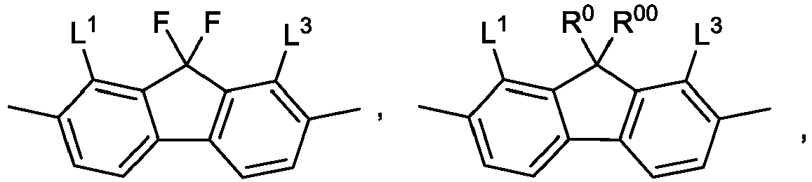


- L1 to L5,
- identically or differently, denote H, F, Cl, Br, I, CN, SF5, CF3, OCF3, or OCHF2, preferably Cl or F, very preferably F, where at least one of the present radicals L1 to L5 in the respective groups is not H,
- RL
- on each occurrence, identically or differently, denotes H, alkyl having 1 to 6 C atoms, alkenyl having 2 to 6 C atoms or alkoxy having 1 to 5 C atoms, preferably H or alkyl having 1 to 4 C atoms, very preferably H, methyl or ethyl,
- RC
- on each occurrence, identically or differently, denotes straight-chain or branched, in each case optionally fluorinated alkyl, alkoxy, alkylthio, alkylcarbonyl, alkoxycarbonyl, alkylcarbonyloxy or alkoxycarbonyloxy having 1 to 12 C atoms or cycloalkyl or alkylcycloalkyl each having 3 to 12 C atoms, preferably methyl, ethyl, isopropyl, cyclopropyl, cyclobutyl, cyclopentyl, cyclohexyl, trifluoromethyl, methoxy, trifluoromethoxy or trifluoromethylthio,
- Sp
- denotes a spacer group or a single bond,
- R0, R00, Rx
- denote straight-chain or branched alkyl having 1 to 6 C atoms,
- R1
- denotes H or straight chain or branched alkyl having 1 to 12 C atoms, preferably H or tert. alkyl, very preferably H or tert.-butyl, in particular H,
- R2 and R3
- identically or differently denote H or straight chain or branched or cyclic alkyl having 1 to 12 C atoms, preferably H, methyl or cyclohexyl, very preferably H or methyl, in particular H.
- r, s, t, u and v,
- identically or differently, are 0, 1 or 2, where r + s + t + u + v is 0, 1, 2, 3 or 4.
- The present invention further relates to a process for the production of the compound of the formula I.
- According to another aspect of the present invention there is provided a switching device comprising, in this sequence,
- a first electrode,
- a molecular layer bonded to the first electrode, and
- a second electrode,
- The invention furthermore relates to a process for the production of the switching device according to the invention comprising at least the following steps:
- i. production of a first electrode having a surface;
- ii. deposition of a molecular layer comprising one or more compounds selected from the group of compounds of the formula I as defined above onto the surface of the first electrode;
- iii. application of a second electrode.
- According to another aspect of the present invention there is provided an electronic component where the component is a memristive crossbar array comprising a multitude of switching devices according to the present invention. Said crossbar array can be integrated into a three-dimensional array of cells comprising a stack of two or more crossbar arrays. Such configurations are known as 3D cross-point or 3D X-point memory devices.
- The invention further relates to the use of a molecular layer obtained from one or more compounds as indicated in
claim 1 in a memristive electronic component. - The resulting devices can be used in memory, sensors, field-effect transistors or Josephson junctions, preferably in resistive memory devices.
- The present invention further relates to the use of the switching devices in memory, sensors, field-effect transistors or Josephson junctions.
- The switching devices according to the invention are suitable for use in electronic components, in particular in memory, sensors, field-effect transistors or Josephson junctions, very particularly in memristive components such as memristive crossbar-arrays, which exhibit the advantageous properties indicated above.
- The compounds of the formula I which comprise a hydroxyaminophosphinic acid or a hydroxyaminophosphinic acid derived anchoring group are surprisingly well soluble in solvents used in the memory industry, in particular in halogenated hydrocarbons (chlorobenzene, trichloroethylene, Solkan-365 (HFC-365mfc, 1,1,1,3,3-pentafluorobutane), or weakly polar esters, ethers and ketones (propylene glycol monomethyl ether acetate (PGMEA), propylene glycol monomethyl ether (PGME), methyl amyl ketone (MAK), ethyl acetate, methyl tert-butyl ether (MTBE), cyclohexanone), but also in common solvents such as γ-butyrolactone, N-methyl pyrrolidone (NMP), tetrahydrofuran (THF), toluene, anisole, chlorobenzene, or CH2Cl2.
- The compounds of the formula I show an improvement of SAM quality and speed of SAM formation, particularly on more acidic substrates with a lower isoelectric point (e.g., TiN, Ta3N5,TaNx, TaON, TazOs, SiO2, ZrO2, HfO2, WO3, RuO2, Cu2O, TiO2, Co2O3) and on metals (e.g., Si, Co, Ni, W, Ru, Cu, Pt via their native oxides or surface oxidation by oxygen plasma, UV/O3 treatment or similar methods).
- The SAM precursors of the formula I and electronic components obtained from the compounds of the formula I are distinguished by a surprisingly high chemical and thermal stability. Switchable electronic components obtained from the compounds of the formula I require only a low voltage and low electrical field strength for switching the device and show a long retention of the resistive state. The switching device exhibits high reliability and endurance and a high stability against dielectric breakdown. Furthermore, the memory window is advantageously large.
- The electrode materials that can be used in the device according to the invention are highly compatible with devices and fabrication processes of the semiconductor industry and are surprisingly well suitable for the formation of a stable and homogeneous molecular monolayer.
-
-
Fig. 1A shows a schematic illustration of the layer structure of a first embodiment of the electronic switching device. -
Fig. 1B shows a schematic illustration of the layer structure of a second embodiment of the electronic switching device according to the invention. -
Fig. 2A shows current-voltage curves of an electronic switching device fabricated using a compound of the state of the art. -
Fig. 2B shows a current-voltage curve of an electronic switching device according to the invention fabricated using a compound of formula I. - The term "diamondoid" refers to substituted and unsubstituted cage compounds of the adamantane series including adamantane, diamantane, triamantane, tetramantanes, pentamantanes, hexamantanes, heptamantanes, octamantanes, and the like, including all isomers and stereoisomers thereof. The compounds have a "diamondoid" topology, which means their carbon atom arrangement is superimposable on a fragment of a face centered cubic diamond lattice. Substituted diamondoids from the first of the series are preferable with 1 to 4 independently-selected alkyl or alkoxy substituents. Diamondoids include "lower diamondoids" and "higher diamondoids," as these terms are defined herein, as well as mixtures of any combination of lower and higher diamondoids. The term "lower diamondoids" refers to adamantane, diamantane and triamantane and any and/or all unsubstituted and substituted derivatives of adamantane, diamantane and triamantane. These lower diamondoid components show no isomers or chirality and are readily synthesized, distinguishing them from "higher diamondoids." The term "higher diamondoids" refers to any and/or all substituted and unsubstituted tetramantane components; to any and/or all substituted and unsubstituted pentamantane components; to any and/or all substituted and unsubstituted hexamantane components; to any and/or all substituted and unsubstituted heptamantane components; to any and/or all substituted and unsubstituted octamantane components; as well as mixtures of the above and isomers and stereoisomers of tetramantane, pentamantane, hexamantane, heptamantane, and octamantane. Adamantane chemistry has been reviewed by Fort, Jr. et al. in "Adamantane: Consequences of the Diamondoid Structure," Chem. Rev. vol. 64, pp. 277-300 (1964). Adamantane is the smallest member of the diamondoid series and may be thought of as a single cage crystalline subunit. Diamantane contains two subunits, triamantane three, tetramantane four, and so on. While there is only one isomeric form of adamantane, diamantane, and triamantane, there are four different isomers of tetramantane, (two of which represent an enantiomeric pair), i.e., four different possible ways or arranging the four adamantane subunits. The number of possible isomers increases non-linearly with each higher member of the diamondoid series, pentamantane, hexamantane, heptamantane, octamantane, etc. Adamantane, which is commercially available, has been studied extensively. The studies have been directed toward a number of areas, such as thermodynamic stability, functionalization, and the properties of adamantane-containing materials. For instance, Schreiber et al., New J. Chem., 2014, 38, 28-41 describes the synthesis and application of functionalized diamondoids to form large area SAMs on silver and gold surfaces. In K. T. Narasimha et al., Nature Nanotechnology 11, March 2016 page 267-273, monolayers of diamondoids are described to effectively confer enhanced field emission properties to metal surfaces due to a significant reduction of the work function of the metal.
- As used herein, an anchor group is a functional group by means of which a compound is adsorbed onto or bonded to the surface of the substrate or electrode by physisorption, chemisorption or by chemical reaction. This chemical reaction includes the transformation of a precursor of an anchor group in situ, for example on the surface of a substrate or electrode.
- A spacer group in the sense of the present invention is a flexible chain between dipolar moiety and anchor group which causes a separation between these sub-structures and, owing to its flexibility, at the same time improves the mobility of the dipolar moiety after bonding to a substrate.
- The spacer group can be branched or straight chain. Chiral spacers are branched and optically active and non-racemic.
- Herein, alkyl is straight-chain or branched and has 1 to 15 C atoms, is preferably straight-chain and has, unless indicated otherwise, 1, 2, 3, 4, 5, 6 or 7 C atoms and is accordingly preferably methyl, ethyl, propyl, butyl, pentyl, hexyl or heptyl.
- Herein, an alkoxy radical is straight-chain or branched and contains 1 to 15 C atoms. It is preferably straight-chain and has, unless indicated otherwise, 1, 2, 3, 4, 5, 6 or 7 C atoms and is accordingly preferably methoxy, ethoxy, propoxy, butoxy, pentoxy, hexoxy or heptoxy.
- Herein, an alkenyl radical is preferably an alkenyl radical having 2 to 15 C atoms, which is straight-chain or branched and contains at least one C-C double bond. It is preferably straight-chain and has 2 to 7 C atoms. Accordingly, it is preferably vinyl, prop-1- or -2-enyl, but-1-, -2- or -3-enyl, pent-1-, -2-, -3- or - 4-enyl, hex-1-, -2-, -3-, -4- or -5-enyl, hept-1-, -2-, -3-, -4-, -5- or -6-enyl. If the two C atoms of the C-C double bond are substituted, the alkenyl radical can be in the form of E and/or Z isomer (trans/cis). In general, the respective E isomers are preferred. Of the alkenyl radicals, prop-2-enyl, but-2- and -3-enyl, and pent-3- and -4-enyl are particularly preferred.
- Herein alkynyl is taken to mean an alkynyl radical having 2 to 15 C atoms, which is straight-chain or branched and contains at least one C-C triple bond. 1-and 2-propynyl and 1-, 2- and 3-butynyl are preferred.
- In the formula I, preferred aryl groups are derived, for example, from the parent structures benzene, naphthalene, tetrahydronaphthalene, 9,10-dihydrophen-anthrene, fluorene, indene and indane.
- In the formula I, preferred heteroaryl groups are, for example, five-membered rings, such as, for example, furan, thiophene, selenophene, oxazole, isoxazole, 1,2-thiazole, 1,3-thiazole, 1,2,3-oxadiazole, 1,2,4-oxadiazole, 1,2,5-oxadiazole, 1,3,4-oxadiazole, 1,2,3-thiadiazole, 1,2,4-thiadiazole, 1,2,5-thiadiazole and 1,3,4-thiadiazole, six-membered rings, such as, for example, pyridine, pyridazine, pyrimidine, pyrazine, 1,3,5-triazine, 1,2,4-triazine and 1,2,3-triazine, or condensed rings, such as, for example, indole, isoindole, indolizine, indazole, benzimidazole, benzotriazole, purine, naphthimidazole, benzoxazole, naphthoxazole, benzothiazole, benzofuran, isobenzofuran, dibenzofuran, thieno[2,3b]thiophene, thieno[3,2b]thiophene, dithienothiophene, isobenzothiophene, dibenzothiophene, benzothiadiazothiophene, 2H-chromen (2H-1-benzopyran), 4H-chromene (4H-1-benzopyran) and coumarin (2H-chromen-2-one), or combinations of these groups.
- In the formula I, preferred cycloaliphatic groups are cyclobutane, cyclopentane, cyclohexane, cyclohexene, cycloheptane, decahydronaphthalene, bicyclo-[1.1.1]pentane, bicyclo[2.2.2]octane, spiro[3.3]heptane and octahydro-4,7-methanoindane.
- Preferred spacer groups Sp are selected from the formula Sp'-X' in which X' is bonded to a ring A1, A2, A3, A4 or B of formula I.
in which - Sp'
- denotes straight-chain or branched alkylene having 1 to 20, preferably 1 to 12 C atoms, which is optionally mono- or poly-substituted by F, Cl, Br, I or CN and in which, in addition, one or more non-adjacent CH2 groups may each be replaced, independently of one another, by -O-, -S-, -NH-, -NR0-, -SiR00R000-, -CO-, -COO-, -OCO-, -OCO-O-, -S-CO-, -CO-S-, -NR0-CO-O-, -O-CO-NR0-, -NR0-CO-NR0-, -CH=CH- or -C≡C- in such a way that O and/or S atoms are not linked directly to one another,
- X'
- denotes -O-, -S-, -CO-, -COO-, -OCO-, -O-COO-, -CO-NR00-, -NR00-CO-, -NR00-CO-NR00-, -OCH2-, -CH2O-, -SCH2-, -CH2S-, -CF2O-, -OCF2-, -CF2S-, -SCF2-, -CF2CH2-, -CH2CF2-, -CF2CF2-, -CH=N-, -N=CH-, -N=N-, -CH=CR00-, -CYx=CYx'-, -C≡C-, -CH=CH-COO-, -OCO-CH=CH- or a single bond,
- R0, R00 and R000
- each, independently of one another, denote H or alkyl having 1 to 12 C atoms, and
- Yx and Yx'
- each, independently of one another, denote H, F, Cl or CN.
- X'
- is preferably -O-, -S-, -CO-, -COO-, -OCO-, -O-COO-, -CO-NR0-, -NR0-CO-, -NR0-CO-NR0- or a single bond.
- Preferred groups Sp' are -(CH2)p1-, -(CF2)p1-, -(CH2CH2O)q1-CH2CH2-, -(CF2CF2O)q1-CF2CF2-, -CH2CH2-S-CH2CH2-, -CH2CH2-NH-CH2CH2- or -(SiR00R000-O)p1-, in which p1 is an integer from 1 to 12, q1 is an integer from 1 to 3, and R00 and R000 have the meanings indicated above.
- Particularly preferred groups -X'-Sp'- are -(CH2)p1-, -O-(CH2)p1-, -(CF2)p1-, -O(CF2)p1-, -OCO-(CH2)p1- and -OC(O)O-(CH2)p1-, in which p1 has the meaning indicated above.
- Particularly preferred groups Sp' are, for example, in each case straight-chain ethylene, propylene, butylene, pentylene, hexylene, heptylene, octylene, nonylene, decylene, undecylene, dodecylene, octadecylene, perfluoroethylene, perfluoropropylene, perfluorobutylene, perfluoropentylene, perfluorohexylene, perfluoroheptylene, perfluorooctylene, perfluorononylene, perfluorodecylene, perfluoroundecylene, perfluorododecylene, perfluorooctadecylene, ethyleneoxyethylene, methyleneoxybutylene, ethylenethioethylene, ethylene-N-methyliminoethylene, 1-methylalkylene, ethenylene, propenylene and butenylene.
- Particularly preferred groups X' are -O- or a single bond.
- The compounds of the general formula I can be prepared as illustrated below by methods known per se, as described in the literature (for example in the standard works, such as Houben-Weyl, Methoden der organischen Chemie [Methods of Organic Chemistry], Georg-Thieme-Verlag, Stuttgart), and under reaction conditions which are known and suitable for the said reactions. Use can be made here of variants known per se which are not mentioned here in greater detail.
- If desired, the starting materials can also be formed in situ by not isolating them from the reaction mixture, but instead immediately converting them further into the compounds of the general formula I.
- The syntheses of compounds of the general formula I according to the invention are described in illustrative terms in the examples. The starting substances can be obtained by generally accessible literature procedures or are commercially available.
- A process according to the invention for the preparation of a compound of formula I in which R1, R2 and R3 denote H (formula lb) via the compound of formula I in which R1 denotes alkyl and R2 and R3 denote H (formula la) comprises the steps of
- a) reaction of a phosphonochloridate of formula II with an O-(trialkylsilyl)hydroxylamine in the presence of a base, to give N-[(alkoxy)phosphoryl]hydroxylamines of formula la, and
- b) ester cleavage of the compound of formula Ia for example with a trialkylsilylhalide, preferably trimethylsilylbromide or trimethylsilyliodide to give the compounds of the formula Ib;
- In scheme 1 R11 denotes straight chain alkyl having 1 to 12 C atoms or branched alkyl having 3 to 12 C atoms and the remaining groups and parameters occurring have the meanings defined above for formula I.
- The phosphonochloridates II are obtainable from dialkyl phosphonates III by known processes, e.g., treatment with an acid chloride, for example with oxalyl chloride, thionyl chloride, phosphorous pentachloride, phosphorous oxychloride, dichlorotriphenyl-phosphorane or phosgene, optionally in the presence of a base, for example pyridine, diazabicyclooctane, or triethylamine.(scheme 2). The dialkylphosphonates (III) can be prepared as described in
WO 2018/007337 A2 ,WO 2019/238649 A2 ,WO 2020/225270 A2 ,WO 2020/225398 A2 ,WO 2021/078699 A2 ,WO 2021/078714 A2 andWO 2021/083934 A2 .
scheme 1. - Preferably, in formula I and its sub-formulae, the radical T denotes


- In another preferred embodiment, in formula I and its sub-formulae the radical T denotes straight chain or branched alkyl having 1 to 12 C atoms, where one or more CH2 groups in these radicals may each be replaced, independently of one another, by -C≡C- , -CH=CH-,


- In a preferred embodiment, the compounds of the formula I are selected from the compounds of the formulae la-1a to la-1d


- T
- denotes H,

- ZT
- denotes CH2O, OCH2, CH2CH2, or a single bond, preferably a single bond
- Z1 and Z2,
- identically or differently, denote CH2O, OCH2, CH2CH2, CF2O, OCF2, C(O)O, OC(O) or a single bond, preferably a single bond,
- A1 and A2,
- identically or differently, denote

- Y' and Y2,
- on each occurrence, identically or differently, denote H, F of CI, preferably H or F, and
- Sp
- denotes branched or unbranched 1,ω-alkylene having 1 to 12 C atoms, in which one or more non-adjacent CH2-groups may be replaced by O, and
- R1
- denotes H.
- Very preferred are the compounds of the formulae la-1b and 1a-1c, in particular la-1c.
- In another preferred embodiment, the compounds of the formula I are selected from the compounds of the formula la-2


- ZT
- denotes a single bond, -CH2O-, -OCH2- or -CH2CH2-,
- Y1 and Y2
- denote H, For CI,
- Y3 and Y4,
- identically or differently, denote methyl, ethyl, isopropyl, cyclopropyl, cyclobutyl, cyclopentyl, cyclopentenyl, cyclohexyl, cyclohexenyl, methoxy, trifluoromethyl, trifluoromethoxy, or trifluoromethylthio,
- Z3
- denotes CH2 or O,
- Z1 and Z4,
- independently of one another, denote a single bond, -C(O)O-,-OC(O)-, -CF2O-, -OCF2-, -CH2O-, OCH2- or -CH2CH2-,
- r and u
- independently are 0, 1 or 2, very preferably u is 0 and r is 0 or 1, and
- R1
- denotes H.
- In formula I and its sub-formulae, the group


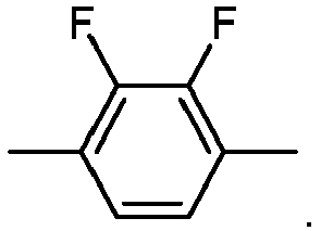
- In a preferred embodiment, the compounds of the formula I are chiral.
- The molecular layers obtained from chiral compounds of the formula I enable memristic devices with significantly further reduced stochastic noise and faster switching, reducing the read and write error rate, which has a positive effect on energy-efficiency. In addition, increased tunnel current are observed allowing for the integration to smaller junction sizes.
- Preferably, the chiral compound has an enantiomeric excess (ee) of above 50%, preferably above 80%, 90%, or 95%, more preferably above 97%, in particular above 98%.
- Chirality is achieved by a branched chiral group Sp of formula I above having one or more, preferably one or two, very preferably one, asymmetrically substituted carbon atom (or: asymmetric carbon atom, C*), hereinafter referred to as Sp*. In Sp* the asymmetric carbon atom is preferably linked to two differently substituted carbon atoms, a hydrogen atom and a substituent selected from the group halogen (preferably F, CI, or Br), alkyl or alkoxy with 1 to 5 carbon atoms in each case, and CN.
- The chiral organic radical Sp* preferably has the formula

- X'
- has the meanings defined above and preferably denotes -CO-O-, -O-CO-, -O-CO-O-, -CO-, -O-, -S-, -CH=CH-, -CH=CH-COO- or a single bond, more preferably -CO-O-, -O-CO-, -O- or a single bond, very preferably -O- or a single bond,
- Q and Q'
- identically or differently, denote a single bond or optionally fluorinated alkylene having 1 to 10 carbon atoms, in which a CH2 group not linked with X can also be replaced by -O-, -CO-, -O-CO-, -CO-O- or -CH=CH-, preferably alkylene having 1 to 10 carbon atoms or a single bond, particularly preferably -(CH2)n5- or a single bond,
- n5
- is 1, 2, 3, 4, 5, or 6,
- Y
- denotes optionally fluorinated alkyl having 1 to 15 carbon atoms, in which one or two non-adjacent CH2 groups can also be replaced by -O-, -CO-, -O-CO-, -CO-O- and/or -CH=CH-, further CN or halogen, preferably optionally fluorinated alkyl or alkoxy having 1 to 7 C atoms, -CN or CI, particularly preferably -CH3, -C2H5, -CF3 or CI,
- In addition, chirality is achieved by a chiral group T of formula I above having one or more, preferably one or two, very preferably one asymmetrically substituted carbon atom (or: asymmetric carbon atom, C*), hereinafter referred to as R*.
- In R* the asymmetric carbon atom is preferably linked to two differently substituted carbon atoms, a hydrogen atom and a substituent selected from the group halogen (preferably F, CI, or Br), alkyl or alkoxy with 1 to 5 carbon atoms in each case, and CN.
- The chiral organic radical preferably has the formula

- X'
- has the meanings defined above for formula I and preferably denotes -CO-O-, -O-CO-, -O-CO-O-, -CO-, -O-, -S-, -CH=CH-, -CH=CH-COO- or a single bond, more preferably -CO-O-, -O-CO-, -O-, or a single bond, very preferably -O- or a single bond,
- Q
- denotes a single bond or optionally fluorinated alkylene having 1 to 10 carbon atoms, in which a CH2 group not linked with X can also be replaced by -O-, -CO-, -O-CO-, -CO-O- or -CH=CH-, preferably alkylene having 1 to 5 carbon atoms or a single bond, particularly preferably -CH2-, -CH2CH2- or a single bond,
- Y
- denotes optionally fluorinated alkyl having 1 to 15 carbon atoms, in which one or two non-adjacent CH2 groups can also be replaced by -O-, -CO-, -O-CO-, -CO-O- and/or -CH=CH-, further CN or halogen, preferably optionally fluorinated alkyl or alkoxy having 1 to 7 C atoms, -CN or CI, particularly preferably -CH3, -C2H5, -CF3 or CI,
- RCh
- denotes an alkyl group having 1 to 15 carbon atoms that is different from Y, in which one or two non-adjacent CH2 groups can also be replaced by -O-, -CO-, -O-CO-, -CO-O- and/or -CH=CH-, preferably denotes straight-chain alkyl having 1 to 10, in particular 1 to 7, carbon atoms, in which the CH2 group linked to the asymmetric carbon atom can be replaced by -O-, -O-CO- or -CO-O-.
- In the memory cell according to the invention, preferably, the first electrodes and/or second electrodes are made from a metal, a conductive alloy, a conductive ceramic, a semiconductor, a conductive oxidic material, conductive or semi conductive organic molecules or a layered conductive 2D material. The first and/or second electrode may comprise combinations of more than one of said materials, for example in form of a multi-layer system. The material of the first and the second electrode may be chosen identically or differently.
- Suitable metals include Ag, Al, Au, Co, Cr, Cu, Mo, Nb, Ni, Pt, Ru, W, Pd, Pt, wherein Al, Cr and Ti are preferred.
- Suitable conductive ceramic materials include CrN, HfN, MoN, NbN, TiO2, RuO2, VO2, NSTO (niobium-doped strontium titanate), TaN and TiN, WN, WCN, VN and ZrN, wherein TiN is preferred.
- Suitable semiconductor materials include indium tin oxide (ITO), indium gallium oxide (IGO), InGa-α-ZnO (IGZO), aluminium-doped zinc oxide (AZO), tin-doped zinc oxide (TZO), fluorine-doped tin oxide (FTO) and antimony tin oxide.
- Suitable element semiconductors include Si, Ge, C (diamond, graphite, graphene, fullerene), α-Sn, B, Se and Te. Suitable compound semiconductors include group III-V semiconductors, in particular GaAs, GaP, InP, InSb, InAs, GaSb, GaN, TaN, TiN, MoN, WN, AIN, InN, Alx Ga1-xAs and InxGa1-x Ni, group II-VI semiconductors, in particular ZnO, ZnS, ZnSe, ZnTe, CdS, CdSe, CdTe, Hg(1-x)Cd(x) Te, BeSe, BeTex and HgS; and group III-VI semiconductors, in particular GaS, GaSe, GaTe, InS, InSex and InTe, group I-III-VI semiconductors, in particular CulnSe2, CulnGaSe2, CulnS2 and CulnGaS2, group IV-IV semiconductors, in particular SiC and SiGe, group IV-VI semiconductors, in particular SeTe.
- Suitable highly doped semiconductor materials include p+Si, n+Si.
- An example of a suitable layered conductive 2D material is graphene.
- Suitable semiconductive organic molecules include polythiophene, tetracene, pentacene, phthalocyanines, PTCDA, MePTCDI, quinacridone, acridone, indanthrone, flavanthrone, perinone, AIQ3 , and mixed systems, in particular PEDOT:PSS and polyvinylcarbazole/TLNQ complexes.
- In a preferred embodiment, the first and second electrodes, identically or differently, comprise a material selected from the group consisting of Ag, Al, Au, Co, Cr, Cu, Mo, Nb, Ni, Pt, Ru, Si, W, CrN, HfN, MoN, NbN, TiN, TaN, Ta3N5,TaNx, TaON, WN, WCN, VN, ZrN, Ta2O5, SiO2, ZrO2, HfO2, WO3, RuO2, Cu2O, TiO2, Co2O3, and niobium-doped strontium titanate.
- More preferably, the first and second electrodes, identically or differently, comprise, preferably consist of a metal nitride selected from CrN, HfN, MoN, NbN, TiN, TaN, WN, tungsten carbide nitride (WCN), VN and ZrN.
- In particular, the first electrode consist of a metal nitride selected from CrN, HfN, MoN, NbN, TiN, TaN, WN, WCN, VN and ZrN, and the second electrode consists of TiN.
- Very particularly, the first and the second electrode both consist of TiN.
- In another preferred embodiment, the first electrode on which the SAM is formed from the compounds of the formula I comprises a material selected from the group consisting of TiN, Ta3N5,TaNx, TaON, Ta2O5, SiO2, ZrO2HfO2, WO3, RuO2, Cu2O, TiO2, Co2O3, Si, Co, Ni, W, Ru, Cu, and Pt and the second electrode comprises a material selected from the group consisting of Ag, Al, Au, Co, Cr, Cu, Mo, Nb, Ni, Pt, Ru, Si, W, CrN, HfN, MoN, NbN, TiN, TaN, WN, WCN, VN and ZrN.
- In the following description of the illustrative embodiments of the invention, identical or similar components and elements are denoted by identical or similar reference numbers, where repeated description of these components or elements is avoided in individual cases. The figures only depict the subjectmatter of the invention schematically.
-
FIG. 1A illustrates a nanoscale non-volatile solid stateresistive device 100 having amolecular switching layer 103 according to an embodiment of the present invention.Device 100 is a two-terminal memory in the present embodiment.Device 100 includes afirst electrode 102, amolecular switching layer 103, and asecond electrode 104.Device 100 is a resistive memory device in the present embodiment but may be other types of device in other embodiments. The molecular switching layer can be selectively set to various resistance values by applying a voltage to the electrodes and reset, using appropriate control circuitry. The resistance of thedevice 100 changes according to the orientation of the molecular dipoles of themolecular switching layer 103.Device 100 is formed over anouter semiconductor substrate 101. The semiconductor substrate may be a silicon substrate, or a compound substrate of a III-V or II-VI type. In an embodiment, the substrate is not made of semiconductor material, e.g., made of plastic. - Particularly suitable substrates are selected from:
- element semiconductors, such as Si, Ge, C (diamond, graphite, graphene, fullerene), α-Sn, B, Se and Te;
- compound semiconductors, preferably
- group III-V semiconductors, in particular GaAs, GaP, InP, InSb, InAs, GaSb, GaN, TaN, TiN, MoN, WN, AIN, InN, AlxGa1-xAs and InxGa1-xNi,
- group II-VI semiconductors, in particular ZnO, ZnS, ZnSe, ZnTe, CdS, CdSe, CdTe, Hg(1-x)Cd(x)Te, BeSe, BeTex and HgS;
- group III-VI semiconductors, in particular GaS, GaSe, GaTe, InS, InSex and InTe,
- group I-III-VI semiconductors, in particular CuInSe2, CuInGaSe2, CuInS2 and CuInGaS2,
- group IV-IV semiconductors, in particular SiC and SiGe,
- group IV-VI semiconductors, in particular SeTe;
- organic semiconductors, in particular polythiophene, tetracene, pentacene, phthalocyanines, PTCDA, MePTCDI, quinacridone, acridone, indanthrone, flavanthrone, perinone, AlQ3, and mixed systems, in particular PEDOT:PSS and polyvinylcarbazole/TLNQ complexes;
- metals, in particular Ta, Ti, Co, Mo, Pt, Ru, Au, Ag, Cu, Al, Wand Mg;
- conductive oxidic materials, in particular indium tin oxide (ITO), indium gallium oxide (IGO), InGa-α-ZnO (IGZO), aluminium-doped zinc oxide (AZO), tin-doped zinc oxide (TZO), fluorine-doped tin oxide (FTO) and antimony tin oxide.
- Preference is given to the use of crystalline silicon as
substrate 101, where silicon wafers having a (100) surface are particularly preferred. Silicon wafers whose surface is oriented at (100) are employed as conventional substrate in microelectronics and are available in high quality and with a low proportion of surface defects. - In the switching devices according to the invention, the molecules of formula I forming the
molecular layer 103 are bonded to thefirst electrode 102 by means of the hydroxyaminophosphinic acid anchor group as defined above in formula I. - The molecular layer may optionally be bonded to a relatively thin (preferably 0.5 - 5 nm thick)
oxidic interlayer 105, for example TiO2, Al2O3, ZrO2, HfO2, or SiO2, which is located on thefirst electrode 102, thus in this embodiment, the first electrode comprises a first layer comprising the material defined inclaim 1 and a second oxidic layer to which themolecular layer 103 is bonded (Fig. 1B ). Hence,first electrode 102 andinterlayer 105 are operable as an alternative first electrode 102'. - The molecular layer of the present invention is a layer of electrically insulating, non-conducting and non-semiconducting organic compounds.
- The molecular layer is essentially formed from precursors of the formula I. Preferably, the precursors used for the formation of the molecular layer consist of compounds of the formula I.
- The thickness of the molecular layer is preferably 10 nm or less, particularly preferably 5 nm or less, very particularly preferably 3 nm or less.
- The molecular layer may consist of one, two, three or more molecule layers comprising compounds of the formula I.
- The molecular layer employed in accordance with the invention is preferably a molecular monolayer.
- In an embodiment, the molecular layer is a self-assembled monolayer (SAM).
- The production of self-assembled monolayers is known to the person skilled in the art; a review is given, for example, in A. Ulman, Chem. Rev. 1996, 96, 1533-1554.
- The degree of coverage of the substrate is preferably 90% to 100%, particularly preferably 95% to 100%, very particularly preferably 98% to 100%.
- Preferably, the
second electrode 104 consists of TiN. - In an embodiment,
first electrodes 102, which in the embodiment ofFigure 1A are implemented in the form of conductor tracks which run perpendicular to the drawing plane, are arranged on thesubstrate 101. - A
second electrode 104, which, like thefirst electrode 102, is in the form of a conductor track, is arranged on the side of themolecular layer 103 facing away from thesubstrate 101. However, thesecond electrode 104 is rotated by 90° relative to thefirst electrode 102, so that a cross-shaped arrangement arises. This arrangement is also called a crossbar array, where the 90° angle is selected here as an example and arrangements in whichsecond electrodes 104 andfirst electrodes 102 cross at an angle deviating from the right angle are also conceivable. Aswitching device 100, which is formed from a layer system having, in this sequence, asecond electrode 104, amolecular layer 103 and afirst electrode 102, is arranged at each crossing point between asecond electrode 104 and afirst electrode 102. In an embodiment a diode is also assigned to eachswitching device 100. - The crossbar array enables each switching
device 100 to be addressed electrically by applying a voltage between the correspondingfirst electrode 102 andsecond electrode 104. - The production and structuring of the electrodes is carried out by means of processes known to the person skilled in the art and is explained in greater detail below with reference to the working examples.
- The structures of the electrodes 102,104 can be produced by means of structuring methods known to the person skilled in the art from microelectronics. For example, a lithography method can be employed for the production of the
first electrodes 102. In this, a metal layer is applied to thesubstrate 101 by means of vapour deposition. The metal layer is subsequently coated with a photoresist, which is exposed with the structures to be produced. After development and, where necessary, baking of the resist, the parts of the metal layer that are not required are removed, for example, by wet-chemical etching. The remaining resist is subsequently removed, for example using a solvent. - A further possibility for the production of the
electrodes electrode - Suitable and preferred processes for the fabrication of the switching device according to the invention are published in
EP 3 813 132 A1 , paragraph [0113] to [0126], which is incorporated by reference. The compounds according to the invention can be used as described therein. - A
substrate 101 whereon a plurality ofdevices 100 is to be defined is provided. The substrate is silicon (p doped, resistivity <0.001 Ω cm-1, prime grade) in the present embodiment. In a preferred embodiment, the silicon substrate comprises a SiO2 layer which serves as an isolating layer and improves derivatization. In other embodiments, other semiconductor materials such as III-V and II-VI type semiconductor compounds may be used as the substrate.Device 100 may be formed as part of a front-end process or a back-end process depending on implementation. Accordingly,substrate 101 may include one or more layers of material formed and patterned thereon when the substrate is provided for the present process. - A first electrode is formed over
substrate 101 using any deposition process, such as, for example, chemical vapor deposition (CVD), plasma enhanced CVD (PECVD), radio-frequency CVD (RFCVD), physical vapor deposition (PVD), atomic layer deposition (ALD), molecular beam deposition (MBD), pulsed laser deposition (PLD), and/or liquid source misted chemical deposition (LSMCD), and/or sputtering, or another deposition or growth process to form at least a top portion of the first electrode. The bottom electrode preferably should comprise a material having a high voltage threshold for ion migration, and it can be blanket or structured by photolithography or other advanced lithography processes known to a person skilled in the art, e.g. nano-imprint lithography or dip-pen lithography. - Optionally, the first electrode is treated with oxygen, argon or nitrogen plasma or UV/ozone in order to obtain a hydrophilic oxidic surface which is populated with hydroxyl groups. It is clear that an oxidic surface of this type merely serves for surface modification with the aim of possible derivatisation via condensation reactions and does not represent an insulator layer or interlayer in the true sense. Sufficiently large tunnel currents through this oxidic surface are possible owing to the low thickness in the order of 1 nm.
- A
molecular layer 103 is formed over thefirst electrode 102. - The deposition of the molecular layer onto the first electrode is carried out with the pure substance or from solution, preferably from solution. Suitable deposition methods and solvents are known to the person skilled in the art; examples are spin coating or dip coating.
- The molecules of the molecular layer are preferably bonded to the first electrode by chemisorption or covalently, more preferably covalently. The bonding is carried out by known methods which are familiar to the person skilled in the art, for example by condensation with hydroxyl groups located on the surface of the substrate.
- In an alternative embodiment, the
molecular layer 103 can also be linked to a first electrode not directly but via a thinoxidic adhesion layer 105 derived from a metal different from that of the first electrode (e.g. Al2O3, ZrO2) and which is deposited onto the first electrode using the deposition techniques mentioned above for the first electrode, preferably CVD. - Preferred is grafting of a molecular layer directly onto a titanium nitride
first electrode 102 by means of molecules of formula I in which the anchor group is a group -P(O)(OH)(NHOH). - In a preferred embodiment, the device is annealed after deposition of the monolayer. The annealing is carried out at a temperature of greater than 20°C and less than 300°C, preferably at greater than 50°C and less than 200°C, particularly preferably at greater than 90°C and less than 150°C. The time duration of the annealing is 1 to 48 h, preferably 4 to 24 h, particularly preferably 8 to 16 h.
- The
first electrode 102 is patterned to obtain an electrode extending along a direction (e.g., horizontal direction). A plurality of first electrodes extending along the first direction in parallel is formed at this step. - Patterned second electrodes are formed on the
molecular layer 103 by a lift-off process using a known processing sequence including a lift-off photoresist, patterning step, electrode deposition, and lift off, or using a photoresist. - The
second electrode 104 can be deposited, e.g., by sputtering or atomic layer deposition, preferably by sputtering. - According to another aspect of the present invention, a plurality of cells is arranged in a three dimensional array of cells. Accordingly, the array extends in two directions of a plane, which may be defined by a substrate onto which the electronic element is formed and may also extend in a vertical direction perpendicular to this plane. A number of cells arranged in the each of the two directions or dimensions of the plane may be very high, ranging from at least two to several thousands, millions or even billions of cells. For example, in a configuration of 1024 cells in an x-direction and 1024 cells in a y-direction, a single two dimensional layer of cells comprises 1048576 cells. Such a twodimensional arrangement of cells, wherein each of the cells is located at a crossing of two orthogonal electrode lines is known as crossbar array.
- The number of levels or layers of cells arranged in the vertical direction or dimension is typically lower and ranges from 2 to at least 64, preferably up to at least 1024 or even higher. Preferably, the array comprises at least 16 levels of cells, more preferably at least 32 levels of cells and most preferred at least 64 levels of cells. Such a three-dimensional arrangement of cells is known as a 3D crossbar array or 3D cross point device.
- The present invention is illustrated in detail by the following non-restrictive working examples.
-

- To a solution of 2,3-difluoro-4-(4-pentylcyclohexyl)phenol (5 g, 17 mmol) in 60 ml of dry DMF potassium carbonate (3.6 g, 26 mmol) is added and the resultant mixture is stirred at room temperature for 1 hour. Then 1,4-dibromobutane (7.3 g, 4.0 ml, 34 mmol) is added, followed by the addition of potassium iodide (0.2 g, 1 mmol). After 18 h of stirring at room temperature, the mixture is filtered off and the filtrate is concentrated in vacuo. The residue is taken up with diethyl ether (100 ml), washed with brine (3 x 50 ml), dried over sodium sulfate and concentrated under reduced pressure to give white solid which is suspended in cold n-pentane, filtered off and washed three times with cold pentane to give 1-(4-bromobutoxy)-2,3-difluoro-4-(4-pentylcyclohexyl)benzene as white solid, m.p. 47 - 48 °C.
- 1H NMR (400 MHz, CDCl3): δ 6.83 (dd, J = 9.2, 2.3 Hz, 1H), 6.68 (dd, J = 7.33, 1.9 Hz, 1H), 4.04 (t, J = 5.7 Hz, 2H), 3.49 (t, J = 6.1 Hz, 2H), 2.82 (tt, J = 12.1, 2.9 Hz, 1H), 2.31 (q, J = 5.9 Hz, 2H), 1.88 - 1.78 (m, 6H), 1.46 - 1.36 (m, 2H), 1.35 - 1.17 (m, 2H), 1.09 - 0.99 (m, 9H), 0.86 (t, 3 J HH = 7.3 Hz, 3H) 13C NMR (101 MHz, CDCl3): δ 149.0 (dd, J = 245.1, 10.2 Hz), 145.6 (dd, J = 8.2, 2.9 Hz), 141.0 (dd, J = 246.9, 15.3 Hz), 128.2 (dd, J = 12.5, 1.3 Hz), 120.3 (dd, J = 5.7, 4.6 Hz), 109.2 (d, J = 3.3 Hz), 67.1 (s), 40.1 (s), 36.7 (s), 33.3 (s), 33.1 (s), 32.4 (s), 31.7 (s), 31.5 (s), 27.7 (s), 23.4 (s), 14.1 (s).
-
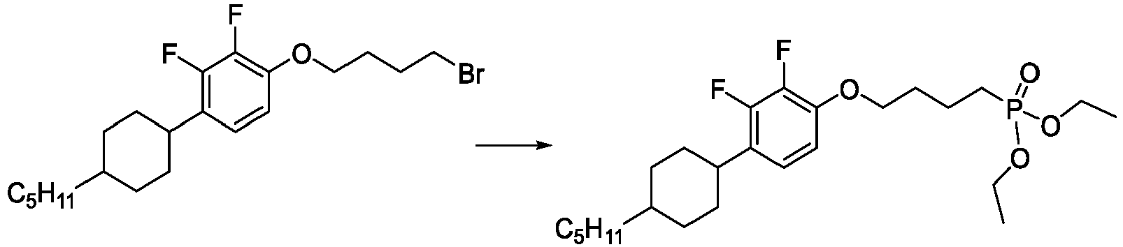
- To a solution of diethyl phosphite (0.69 g, 0.64 ml, 5 mmol) in 80 ml of dry THF cooled to 0 °C sodium hydride (0.24 g, 6 mmol, 60 % dispersion in oil) is added portionwise. It is stirred 30 min at 0 °C and then a solution of 1-(4-bromobutoxy)-2,3-difluoro-4-(4-pentylcyclohexyl)benzene (2 g, 5 mmol) in 5 ml of anhydrous THF is added. The resultant mixture is then stirred at 66 °C for 4 h. The reaction is quenched with 1M solution of HCl (100 ml), organic phase is separated and water phase is extracted with diethyl ether (3 x 30 ml). Organic phase is then dried over Na2SO4, filtered off and the solvent is evaporated to give an oily residue which is purified by column chromatography eluting with ethyl acetate to give diethyl (4-(2,3-difluoro-4-(4-pentylcyclohexyl)phenoxy)butyl)phosphonate as a yellowish oil.
- 1H NMR (401 MHz, CDCl3): δ 6.81 (t, J = 8.2 Hz, 1H), 6.63 (t, J = 8.1 Hz, 1H), 4.15 - 4.02 (m, 4H), 4.01 (dd, J = 11.7, 5.9 Hz, 2H), 2.70 (tt, J = 12.1, 1.1 Hz, 1H), 1.85 (dt, J = 21.4, 11.1 Hz, 9H), 1.50 - 1.11 (m, 16H), 1.05 (dd, J = 17.1, 6.4 Hz, 2H), 0.87 (t, J = 6.7 Hz, 3H); 19F NMR (377 MHz, CDCl3): δ -143.15 (dd, J = 19.6, 7.4 Hz, 1F), -159.47 (ddd, J = 19.6, 7.6, 2.1 Hz, 1F); 31P NMR (162 MHz, CDCl3): δ 32.42 (s, 1P).
-

- Oxalyl chloride (200 mg, 1.6 mmol) is added dropwise to a stirred solution of diethyl (4-(2,3-difluoro-4-(4-pentylcyclohexyl)phenoxy)butyl)phosphonate (780 mg, 1.6 mmol) dissolved in 5 ml of dry dichloromethane at room temperature. When addition is complete, the mixture is stirred for another 4 h under reflux. Afterwards all volatiles are removed in vacuo to give ethyl (4-(2,3-difluoro-4-(4-pentylcyclohexyl)phenoxy)butyl)-phosphonochloridate as a yellow oil. 1H NMR (401 MHz, CDCl3): δ 6.83 (td, J = 8.3, 2.6 Hz, 1H), 6.64 (td, J = 7.7, 1.9 Hz, 1H), 4.37 - 4.27 (m, 1H), 4.27 - 4.18 (m, 1H), 4.03 (t, J = 5.4 Hz, 2H), 2.80 - 2.66 (m, 1H), 2.23 (dt, J = 15.1, 6.5 Hz, 2H), 2.00 - 1.88 (m, 3H), 1.49 - 1.39 (m, 4H), 1.41 - 1.37 (m, 6H), 1.35 - 1.17 (m, 9H), 1.12 - 0.98 (m, 2H), 0.88 (t, J = 6.6 Hz, 3H); 19F NMR (377 MHz, CDCl3): δ -143.15 (dd, J = 19.6, 7.4 Hz, 1F), -159.47 (dd, J = 19.6, 7.6, 1F); 31P NMR (162 MHz, CDCl3): δ 44.62 (s, 1P)
-

- A solution of ethyl (4-(2,3-difluoro-4-(4-pentylcyclohexyl)phenoxy)butyl)-phosphonochloridate (760 mg, 1.6 mmol) in 1 ml of dry dichloromethane is added at 0 °C to a stirred mixture of O-trimethylsilylhydroxylamine (180 mg, 1.8 mmol) and triethylamine (159 mg, 0.22 ml, 1.8 mmol) in dry dichloromethane (20 ml). After further 5 h at room temperature, volatile matter is evaporated, ether (10 ml) is added and the solid (Et3NHCl) is filtered off. The filtrate is treated with methanol (3 ml) for 10 min to effect desilylation and is then evaporated to dryness to give an oily residue which is purified by column chromatography eluting with ethyl acetate to give the ethyl P-(4-(2,3-difluoro-4-(4-pentylcyclohexyl)phenoxy)butyl)-N-hydroxyphosphonamidate.
- 1H NMR (401 MHz, CDCl3): δ 6.82 (t, J = 8.2 Hz, 1H), 6.62 (t, J = 8.2 Hz, 1H), 4.16 - 4.10 (m, 4H), 3.90 (t, J = 5.9 Hz, 2H), 2.71 (t, J = 12.3 Hz, 1H), 1.76 - 1.96 (m, 4H), 1.48 - 1.32 (m, 9H), 1.26 (ddd, J = 22.9, 13.6, 6.0 Hz, 4H), 1.04 (q, J = 11.8 Hz, 2H), 0.88 (t, J = 6.8 Hz, 3H); 19F NMR (377 MHz, CDCl3): δ -143.06 (d, J = 19.6 Hz, 1F), -159.37 (d, J = 20.2 Hz, 1F); 31P NMR (162 MHz, CDCl3): δ 26.91 (s, 1P)
-

- Bromotrimethylsilane (3.5 g, 3 ml, 22 mmol) is added to neat ethyl P-(4-(2,3-difluoro-4-(4-pentylcyclohexyl)phenoxy)butyl)-N-hydroxyphosphonamidate (0.33 g, 0.77 mmol)) under argon. The resulting solution is stirred at room temperature for 24 h. Volatile materials are removed in vacuo and the residue is treated with methanol (2 ml). After stirring for 12 h at room temperature the solvent is evaporated under reduced pressure to give P-(4-(2,3-difluoro-4-(4-pentylcyclohexyl)phenoxy)butyl)-N-hydroxyphosphonamidic acid as a solid. 1H NMR (401 MHz, DMSO-d6): δ 10.36 (s, 3H), 6.81 (t, J = 8.2 Hz, 1H), 6.63 (t, J = 8.2 Hz, 1H), 3.99 (t, J = 5.9 Hz, 2H), 2.71 (t, J = 12.3 Hz, 1H), 1.76 - 1.96 (m, 4H), 1.48 - 1.32 (m, 9H), 1.26 (ddd, J = 22.9, 13.6, 6.0 Hz, 4H), 1.04 (q, J = 11.8 Hz, 2H), 0.88 (t, J = 6.8 Hz, 3H); 19F NMR (377 MHz, DMSO-d6): δ -143.06 (d, J = 19.6 Hz, 1F), -159.37 (d, J = 20.2 Hz, 1F); 31P NMR (162 MHz, DMSO-d6): δ 26.91 (s, 1P); 13C NMR (101 MHz, DMSO-d6): δ 149.4 (dd, J = 245.1, 10.2 Hz), 146.0 (dd, J = 8.2, 2.9 Hz), 141.5 (dd, J = 246.9, 15.3 Hz), 128.7 (dd, J = 12.5, 1.3 Hz), 121.5 (dd, J = 5.7 Hz, 4.6 Hz), 110.3 (d, J = 2.0 Hz), 69.29 (s), 33.48 (s), 32.99 (s), 30.12 (s), 29.86 (s), 28.51 (d, J = 135.8 Hz), 27.10 (s), 26.51 (s), 22.60 (s), 19.99 (s), 19.95 (s), 14.49 (s).
-


- Test chips are prepared by the following steps in this order using the acids compound A (Synthesis Example 1) and for comparison with compound B from the state of the art:
- 1. Preparation of N-hydroxylamidophosphonic acid A and phosphonic acid B (as reference) solution in THF (c = 1 mmol/l)
- 2. UV ozone treatment 15 min of test chips: 1) 8x8 mm p++Si (525 µm)/Al2O3 (2-3 nm, deposited by ALD), and 2) 8x8 mm p++Si (525 µm)/Ti (10 nm, sputtered)/TiN (30 nm, sputtered)
- 3. Immersion of
chip - 4. Drying in a stream of N2 gas
- 5. Bake (T = 120°C) in N2 atmosphere for 1 h
- 6. Cleaning by short rinsing with THF
- 7. Drying in a stream of N2 gas
-
Test chip Compound WCA 1A A 105.3° 1B B 104.7° 2A A 115.0° 2B B 115.8° - The WCAs for A are at approx. on the same level as the reference compounds B on Al2O3 (1) as well as on TiN (2) substrates.
- Comparative current-voltage (IV) characteristics are recorded using a standard setup as described for example in
EP 3 481916 A1 . -
Fig. 2A shows the IV characteristics (200, absolute current density vs. voltage) of reference compound B on a TiN substrate (8x8 mm p++Si (525 µm)/Ti (10 nm, sputtered)/TiN (30 nm, sputtered); contacted by a Hg droplet with ca. 160 mm diameter.Fig. 2B shows the IV characteristics (300, absolute current density vs. voltage) of compound A according to the invention on a TiN substrate (8x8 mm p++Si (525 µm)/Ti (10 nm, sputtered)/TiN (30 nm, sputtered); contacted by a Hg droplet with ca. 160 mm diameter. Theupper curves 200 show the result of foursweeps lower curves 300 show the result of foursweeps - In analogy to Synthesis Example 1 the following compounds are obtained:
2 
3 
4 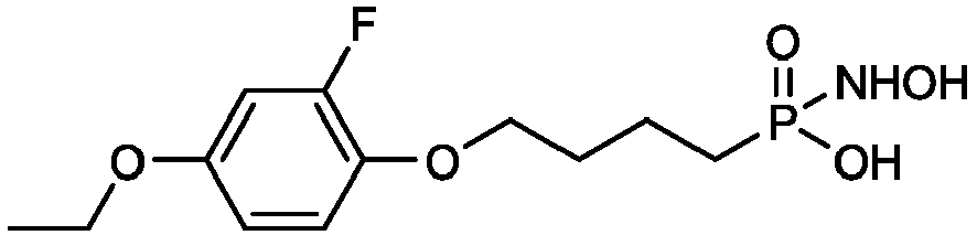
5 
6 
7 
8 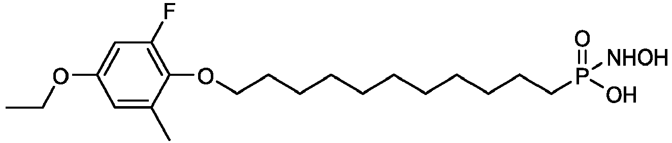
9 
10 
11 
12 
13 
14 
15 

16 
17 
18 
19 
20 
21 
22 23 
24 
25 
26 
27 
28 
29 
30 
31 
32 
33 
34 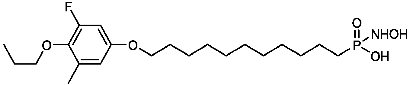
35 
36 
37 
38 
39 
40 
41 
42 
43 
44 
45 
46 
47 
48 
49 
50 
51 
52 
53 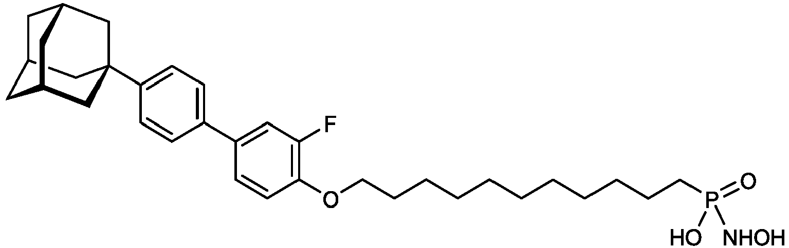
54 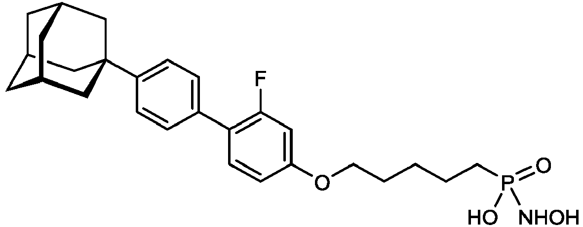
55 
56 
57 
58 
59 
60 
61 
62 
63 
64 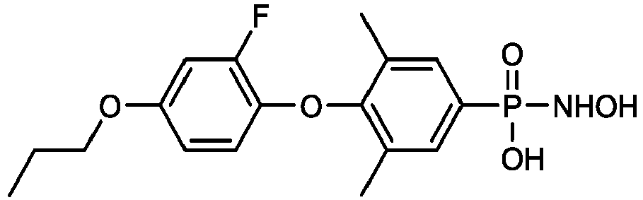
65 
66 
67 
68 
69 
70 
71 
72 
73 
74 
75 
76 
77 
78 
79 
80 
81 
82 
83 
84 
85 
86 
87 
88 
89 
90 
91 
92 
93 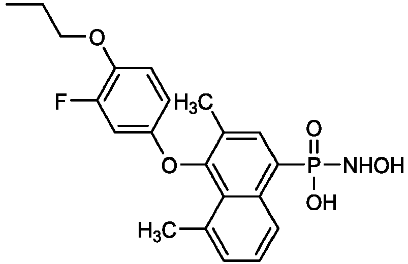
94 
95 
96 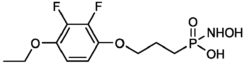
97 
98 
99 
100 
101 
102 
103 
104 
105 
106 
107 
108 
109 
110 
111 
112 
113 
114 
115 
116 
117 
118 
119 
120 
121 
122 
123 
124 
125 
126 
127 
128 
129 
130 
131 
132 
133 
134 
135 
136 
137 
138 
139 
140 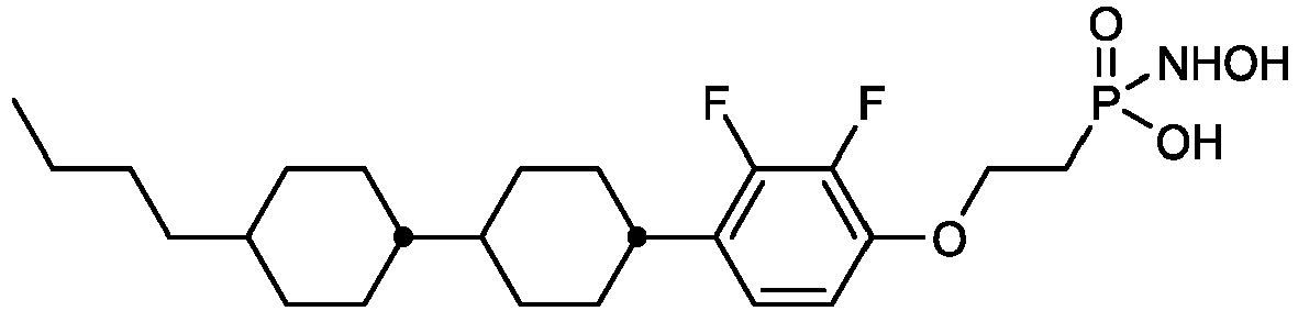
141 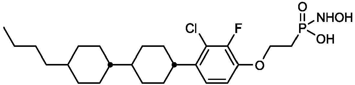
142 
143 
144 
145 
146 
147 
148 
149 
150 
151 
152 
153 
154 
155 
156 
157 
158 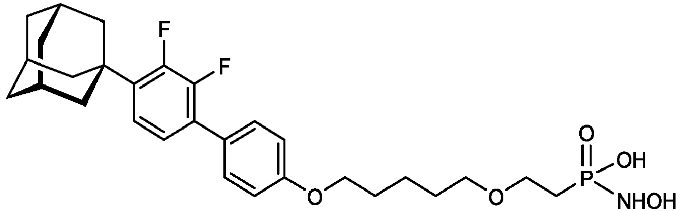
159 
160 
161 
162 
163 
164 
165 
166 
167 
168 
169 
170 
171 
172 
173 
174 
175 
176 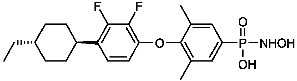
177 
178 
179 
180 
181 
182 
183 
184 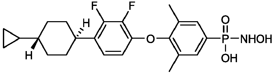
185 
186 
187 
188 
189 
190 
191 
192 
193 
194 
195 
196 
197 
198 
199 
200 
200 
201 
202 
203 
204 
205 
206 
207 
208 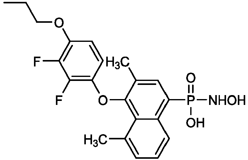
209 
210 
211 
212 
213 
214 
215 
216 
217 
218 
219 
220 
221 
222 
223 
224 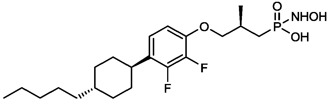
225 
226 
227 
228 
229 
230 
231 
232 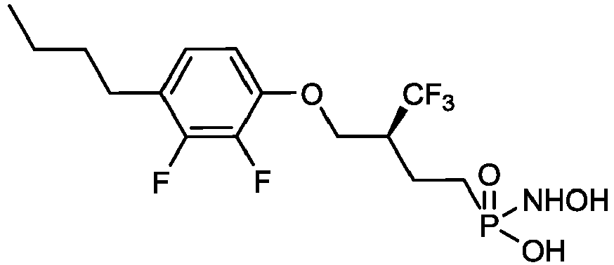
233 
234 
235 
236 
237 
238 
239 
240 
241 
242 
243 
244 
245 

Claims (16)
- A compound of formula I

T is selected from the group of radicals consisting of the following groups:a) straight chain or branched alkyl or alkoxy each having 1 to 20 C atoms, where one or more CH2 groups in these radicals may each be replaced, independently of one another, by -C≡C- , -CH=CH-,
 b) a three- to ten-membered saturated or partially unsaturated aliphatic ring, in which at least one -CH2- group is replaced with -O-, -S-, -S(O)-, -SO2-, -NRx- or -N(O)Rx-, or in which at least one -CH= group is replaced with -N=,c) a diamondoid radical,where r + s + t + u + v is 0, 1, 2, 3 or 4.ZT, Z1, Z2, and Z4, on each occurrence, identically or differently, denote a single bond, -CF2O-, -OCF2-, -CF2S-, -SCF2-, -CH2O-, -OCH2-, -C(O)O-, -OC(O)-, -C(O)S-,-SC(O)-, -(CH2)n1-, -(CF2)n2-, -CF2 CH2-, -CH2CF2-, -CH=CH-,-CF=CF-,-CF=CH-, -CH=CF-, -(CH2)n3O-, -O(CH2)n4-, -C≡C-, -O-, -S-, -CH=N-,-N=CH-, -N=N-,-N=N(O)-, -N(O)=N- or-N=C-C=N-, wherein n1, n2, n3, n4, identically or differently, are 1, 2, 3, 4, 5, 6, 7, 8, 9 or 10,Z3 denotes -O-, -S-, -CH2-, -C(O)-, -CF2-, -CHF-, -C(Rx)2-, -S(O)- or -SO2-,
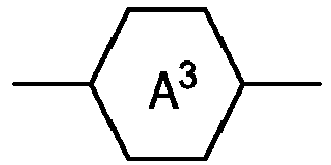 Y on each occurrence, identically or differently, denotes F, Cl, CN, SCN, SF5 or straight-chain or branched, in each case optionally fluorinated alkyl, alkoxy, alkylcarbonyl, alkoxycarbonyl, alkylcarbonyloxy or alkoxycarbonyloxy having 1 to 12 C atoms,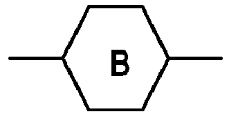
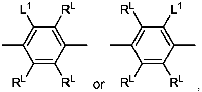


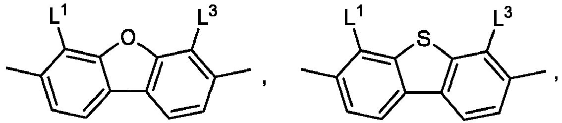


 L1 to L5, identically or differently, denote H, F, Cl, Br, I, CN, SFs, CF3, OCF3, or OCHF2, where at least one of the present radicals L1 to L5 in the respective groups is not H,RL on each occurrence, identically or differently, denotes H, alkyl having 1 to 6 C atoms, alkenyl having 2 to 6 C atoms or alkoxy having 1 to 5 C atoms,RC on each occurrence, identically or differently, denotes straight-chain or branched, in each case optionally fluorinated alkyl, alkoxy, alkylthio, alkylcarbonyl, alkoxycarbonyl, alkylcarbonyloxy or alkoxycarbonyloxy having 1 to 12 C atoms or cycloalkyl or alkylcycloalkyl each having 3 to 12 C atoms,Sp denotes a spacer group or a single bond,R0, R00, Rx denote straight-chain or branched alkyl having 1 to 6 C atoms,R1 denotes H or straight chain or branched alkyl having 1 to 12 C atoms,R2 and R3 identically or differently denote H or straight chain or branched or cyclic alkyl having 1 to 12 C atoms,r, s, t, u and v, identically or differently, are 0, 1 or 2,
 - The compound according to claim 1, in which R2 and R3 denote H.
- The compound according to claim 1 or 2, wherein the compound is selected from the compounds of the formulae la-1a to la-1d


- The compound according to one or more of claims 1 to 3, whereinT denotes H,
 ZT denotes CH2O, OCH2, CH2CH2, or a single bond,Z1 and Z2, identically or differently, denote CH2O, OCH2, CH2CH2, CF2O, OCF2, C(O)O, OC(O) or a single bond,

 Y1 and Y2, on each occurrence, identically or differently, denote H, F of Cl,Sp denotes branched or unbranched 1,ω-alkylene having 1 to 12 C atoms, in which one or more non-adjacent CH2-groups may be replaced by O,R1 denotes H,and
- The compound according to claim 1 or 2, wherein the compound is selected from the compounds of the formula la-2


- The compound according to claim 5, wherein


 A3-Z3 denotes
 ZT denotes a single bond, -CH2O-, -OCH2- or -CH2CH2-,Y1 and Y2 denote H, F or Cl,Y3 and Y4 denote methyl, ethyl, isopropyl, cyclopropyl, cyclobutyl, cyclopentyl, cyclopentenyl, cyclohexyl, cyclohexenyl, methoxy, trifluoromethyl, trifluoromethoxy, or trifluoromethylthio,Z3 denotes CH2 or O,Z1 and Z4, independently of one another, denote a single bond, -C(O)O-,-OC(O)-, -CF2O-, -OCF2-, -CH2O-, OCH2- or -CH2CH2-,r and u independently are 0, 1 or 2.
 - The compound according to one or more of claims 1 to 6, wherein the group


- A process for the preparation of a compound of formula Ib comprising the steps ofa) reaction of a phosphonochloridate of formula II with an O-(trialkylsilyl)hydroxylamine in the presence of a base to give N-[(alkoxy)phosphoryl]hydroxylamines of formula la, andb) ester cleavage of the compound of formula Ia to give the compounds of the formula Ib
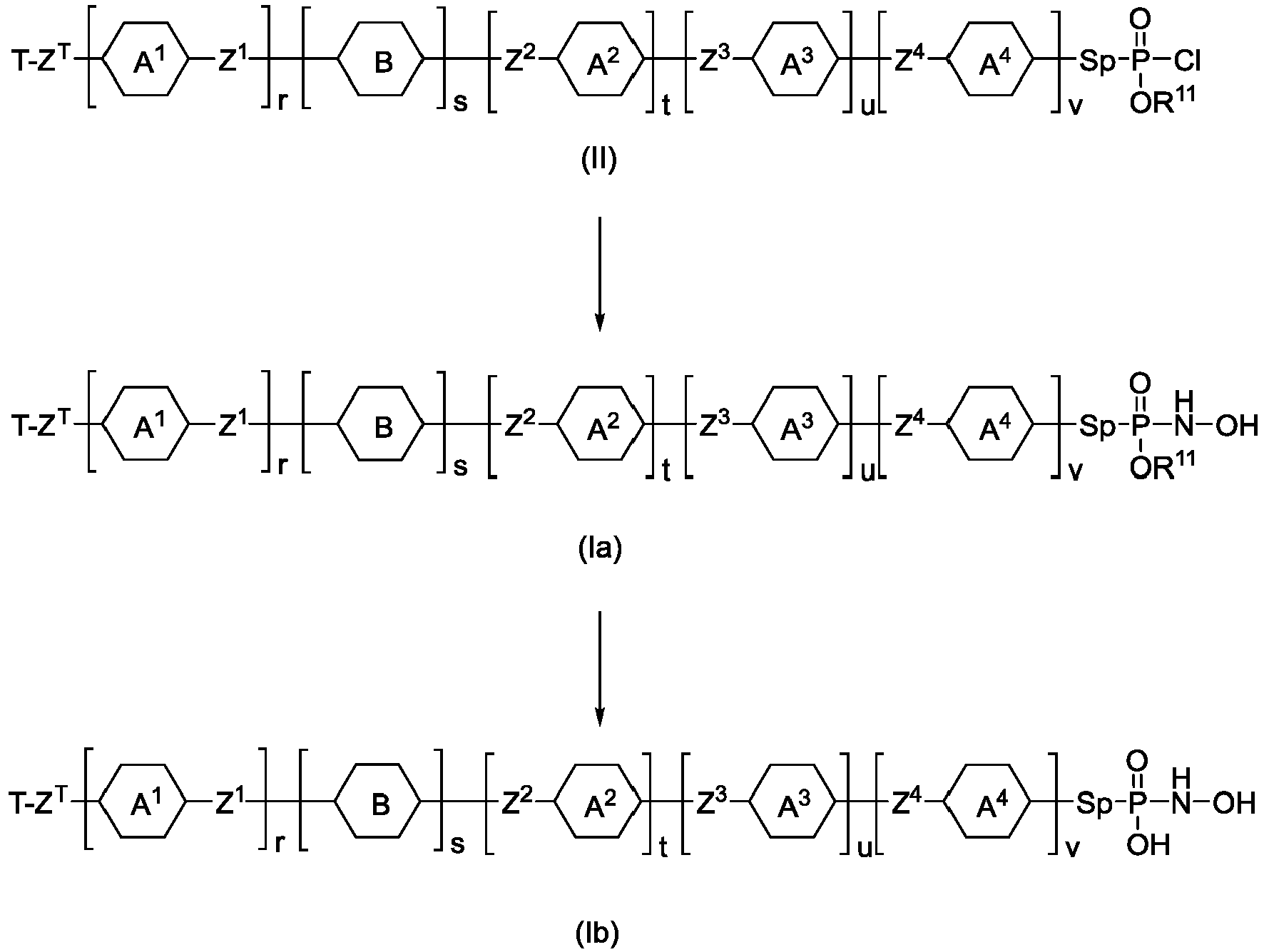


R11 denotes straight chain alkyl having 1 to 12 C atoms or branched alkyl having 3 to 12 C atoms. - An electronic switching device (100) which comprises, in this sequence, a first electrode (102),a molecular layer (103) bonded to the first electrode, anda second electrode (104),wherein the first and second electrodes (102, 104), identically or differently, preferably comprise a material selected from Ag, Al, Au, Co, Cr, Cu, Mo, Nb, Ni, Pt, Ru, Si, W, CrN, HfN, MoN, NbN, TiN, TaN, Ta3N5,TaNx, TaON, WN, WCN, VN, ZrN, Ta2O5, SiO2, ZrO2, HfO2, WO3, RuO2, Cu2O, TiO2, Co2O3, and niobium-doped strontium titanate,characterised in that the molecular layer (103) is essentially formed from one or more compounds of formula I according to one or more of claims 1 to 6.
- Electronic switching device (100) according to claim 7, wherein an interlayer (105) is arranged between the first electrode (102) and the molecular layer (103), where the interlayer (105) comprises an oxidic material and where the molecular layer (103) is bonded to said oxidic material, and where the first electrode (102) and the interlayer (105) are operable as a first electrode (102').
- Electronic switching device (100) according to claim 9 or 10, wherein the one or more compounds of the formula I are bonded to the first electrode (102) by chemisorption or covalently.
- Electronic switching device (100) according to one or more of claims 9 to 11, wherein the molecular layer (103) is a molecular monolayer.
- Electronic component comprising one or more switching devices (100) according to one or more of claims 8 to 11.
- Electronic component according to claim 13, wherein the component has a multitude of switching devices (100), where the first electrodes (102) and second electrodes (104) of the switching devices (100) form a crossbar array.
- Electronic component according to claim 13 or 14, wherein the switching devices (100) are configured to change between a state having high electrical resistance and a state having low electrical resistance, where the quotient between high electrical resistance and low electrical resistance is between 10 and 100,000.
- Use of a compound of formula I according to claim 1 for the fabrication of a self-assembled monolayer.
Priority Applications (6)
| Application Number | Priority Date | Filing Date | Title |
|---|---|---|---|
| EP22199535.0A EP4349842A1 (en) | 2022-10-04 | 2022-10-04 | Hydroxyaminophosphinic acid derivatives |
| PCT/EP2023/077007 WO2024074413A1 (en) | 2022-10-04 | 2023-09-29 | Hydroxyaminophosphinic acid derivatives |
| KR1020257014419A KR20250076645A (en) | 2022-10-04 | 2023-09-29 | Hydroxyaminophosphinic acid derivatives |
| JP2025519707A JP2025533346A (en) | 2022-10-04 | 2023-09-29 | Hydroxyaminophosphinic acid derivatives |
| CN202380070283.4A CN119998303A (en) | 2022-10-04 | 2023-09-29 | Hydroxyaminophosphinic acid derivatives |
| TW112137855A TW202428593A (en) | 2022-10-04 | 2023-10-03 | Hydroxyaminophosphinic acid derivatives |
Applications Claiming Priority (1)
| Application Number | Priority Date | Filing Date | Title |
|---|---|---|---|
| EP22199535.0A EP4349842A1 (en) | 2022-10-04 | 2022-10-04 | Hydroxyaminophosphinic acid derivatives |
Publications (1)
| Publication Number | Publication Date |
|---|---|
| EP4349842A1 true EP4349842A1 (en) | 2024-04-10 |
Family
ID=83593858
Family Applications (1)
| Application Number | Title | Priority Date | Filing Date |
|---|---|---|---|
| EP22199535.0A Pending EP4349842A1 (en) | 2022-10-04 | 2022-10-04 | Hydroxyaminophosphinic acid derivatives |
Country Status (6)
| Country | Link |
|---|---|
| EP (1) | EP4349842A1 (en) |
| JP (1) | JP2025533346A (en) |
| KR (1) | KR20250076645A (en) |
| CN (1) | CN119998303A (en) |
| TW (1) | TW202428593A (en) |
| WO (1) | WO2024074413A1 (en) |
Citations (8)
| Publication number | Priority date | Publication date | Assignee | Title |
|---|---|---|---|---|
| WO2016110301A1 (en) | 2015-01-07 | 2016-07-14 | Merck Patent Gmbh | Electronic component |
| WO2018007337A2 (en) | 2016-07-07 | 2018-01-11 | Merck Patent Gmbh | Electronic switching element |
| WO2019238649A1 (en) | 2018-06-14 | 2019-12-19 | Merck Patent Gmbh | Method for producing an electronic component which includes a self-assembled monolayer |
| WO2020225270A1 (en) | 2019-05-09 | 2020-11-12 | Merck Patent Gmbh | Diamondoid compounds |
| WO2020225398A1 (en) | 2019-05-09 | 2020-11-12 | Merck Patent Gmbh | Aromatic compounds |
| EP3813132A1 (en) | 2019-10-21 | 2021-04-28 | Merck Patent GmbH | Electronic switching device |
| WO2021078714A1 (en) | 2019-10-23 | 2021-04-29 | Merck Patent Gmbh | Two bit memory device and method for operating the two-bit memory device and electronic component |
| WO2021083934A1 (en) | 2019-10-29 | 2021-05-06 | Merck Patent Gmbh | Process for the production of a molecular layer and electronic component comprising same |
-
2022
- 2022-10-04 EP EP22199535.0A patent/EP4349842A1/en active Pending
-
2023
- 2023-09-29 JP JP2025519707A patent/JP2025533346A/en active Pending
- 2023-09-29 KR KR1020257014419A patent/KR20250076645A/en active Pending
- 2023-09-29 WO PCT/EP2023/077007 patent/WO2024074413A1/en not_active Ceased
- 2023-09-29 CN CN202380070283.4A patent/CN119998303A/en active Pending
- 2023-10-03 TW TW112137855A patent/TW202428593A/en unknown
Patent Citations (10)
| Publication number | Priority date | Publication date | Assignee | Title |
|---|---|---|---|---|
| WO2016110301A1 (en) | 2015-01-07 | 2016-07-14 | Merck Patent Gmbh | Electronic component |
| WO2018007337A2 (en) | 2016-07-07 | 2018-01-11 | Merck Patent Gmbh | Electronic switching element |
| EP3481916A2 (en) | 2016-07-07 | 2019-05-15 | Merck Patent GmbH | Electronic switching element |
| WO2019238649A1 (en) | 2018-06-14 | 2019-12-19 | Merck Patent Gmbh | Method for producing an electronic component which includes a self-assembled monolayer |
| WO2020225270A1 (en) | 2019-05-09 | 2020-11-12 | Merck Patent Gmbh | Diamondoid compounds |
| WO2020225398A1 (en) | 2019-05-09 | 2020-11-12 | Merck Patent Gmbh | Aromatic compounds |
| EP3813132A1 (en) | 2019-10-21 | 2021-04-28 | Merck Patent GmbH | Electronic switching device |
| WO2021078699A1 (en) | 2019-10-21 | 2021-04-29 | Merck Patent Gmbh | Electronic switching device |
| WO2021078714A1 (en) | 2019-10-23 | 2021-04-29 | Merck Patent Gmbh | Two bit memory device and method for operating the two-bit memory device and electronic component |
| WO2021083934A1 (en) | 2019-10-29 | 2021-05-06 | Merck Patent Gmbh | Process for the production of a molecular layer and electronic component comprising same |
Non-Patent Citations (6)
| Title |
|---|
| A. ULMAN, CHEM. REV., vol. 96, 1996, pages 1533 - 1554 |
| FORT, JR. ET AL.: "Adamantane: Consequences of the Diamondoid Structure", CHEM. REV., vol. 64, 1964, pages 277 - 300 |
| HARGER MARTIN J. P. ET AL: "N-phosphonoyl and N-phosphoroyl hydroxylamines: reactions of their O-sulphonyl derivatives with t-butylamine", JOURNAL OF THE CHEMICAL SOCIETY, PERKIN TRANSACTIONS 1, 1 January 1985 (1985-01-01), Cambridge, UK, pages 2651, XP093029005, ISSN: 0300-922X, DOI: 10.1039/p19850002651 * |
| K. T. NARASIMHA ET AL., NATURE NANOTECHNOLOGY, 11 March 2016 (2016-03-11), pages 267 - 273 |
| MAHAJNA MAHMOUD ET AL: "Oxidative Bioactivation of Methamidophos Insecticide:? Synthesis of N -Hydroxymethamidophos (A Candidate Metabolite) and Its Proposed Alternative Reactions Involving N -> O Rearrangement or Fragmentation through a Metaphosphate Analogue", CHEMICAL RESEARCH IN TOXICOLOGY, vol. 11, no. 1, 1 January 1998 (1998-01-01), US, pages 26 - 34, XP093029004, ISSN: 0893-228X, DOI: 10.1021/tx9701135 * |
| SCHREIBER ET AL., NEW J. CHEM., vol. 38, 2014, pages 28 - 41 |
Also Published As
| Publication number | Publication date |
|---|---|
| WO2024074413A1 (en) | 2024-04-11 |
| JP2025533346A (en) | 2025-10-06 |
| CN119998303A (en) | 2025-05-13 |
| TW202428593A (en) | 2024-07-16 |
| KR20250076645A (en) | 2025-05-29 |
Similar Documents
| Publication | Publication Date | Title |
|---|---|---|
| EP4062453B1 (en) | Electronic switching device | |
| EP3966870B1 (en) | Aromatic compounds | |
| EP3966871B1 (en) | Diamondoid compounds | |
| EP4349842A1 (en) | Hydroxyaminophosphinic acid derivatives | |
| EP4247138A1 (en) | Electronic switching device | |
| EP4174077A1 (en) | Electronic switching device | |
| EP4102571B1 (en) | Electronic element comprising a plurality of cells arranged in a three dimensional array of cells and method for producing such an electronic device | |
| US20250011349A1 (en) | Electronic switching device | |
| KR102954479B1 (en) | aromatic compounds |
Legal Events
| Date | Code | Title | Description |
|---|---|---|---|
| PUAI | Public reference made under article 153(3) epc to a published international application that has entered the european phase |
Free format text: ORIGINAL CODE: 0009012 |
|
| STAA | Information on the status of an ep patent application or granted ep patent |
Free format text: STATUS: REQUEST FOR EXAMINATION WAS MADE |
|
| 17P | Request for examination filed |
Effective date: 20221004 |
|
| AK | Designated contracting states |
Kind code of ref document: A1 Designated state(s): AL AT BE BG CH CY CZ DE DK EE ES FI FR GB GR HR HU IE IS IT LI LT LU LV MC ME MK MT NL NO PL PT RO RS SE SI SK SM TR |
|
| STAA | Information on the status of an ep patent application or granted ep patent |
Free format text: STATUS: EXAMINATION IS IN PROGRESS |
|
| 17Q | First examination report despatched |
Effective date: 20240927 |
|
| GRAP | Despatch of communication of intention to grant a patent |
Free format text: ORIGINAL CODE: EPIDOSNIGR1 |
|
| STAA | Information on the status of an ep patent application or granted ep patent |
Free format text: STATUS: GRANT OF PATENT IS INTENDED |
|
| RIC1 | Information provided on ipc code assigned before grant |
Ipc: C07F 9/44 20060101AFI20260107BHEP Ipc: C07F 9/655 20060101ALI20260107BHEP Ipc: C07F 9/6553 20060101ALI20260107BHEP Ipc: H10K 85/60 20230101ALI20260107BHEP |
|
| INTG | Intention to grant announced |
Effective date: 20260130 |
|
| GRAS | Grant fee paid |
Free format text: ORIGINAL CODE: EPIDOSNIGR3 |
|
| GRAA | (expected) grant |
Free format text: ORIGINAL CODE: 0009210 |
|
| STAA | Information on the status of an ep patent application or granted ep patent |
Free format text: STATUS: THE PATENT HAS BEEN GRANTED |