EP4349713A1 - High-power air-coooled compressor motor and low-power cooling booster fan motor powered by single inverter - Google Patents
High-power air-coooled compressor motor and low-power cooling booster fan motor powered by single inverter Download PDFInfo
- Publication number
- EP4349713A1 EP4349713A1 EP23198535.9A EP23198535A EP4349713A1 EP 4349713 A1 EP4349713 A1 EP 4349713A1 EP 23198535 A EP23198535 A EP 23198535A EP 4349713 A1 EP4349713 A1 EP 4349713A1
- Authority
- EP
- European Patent Office
- Prior art keywords
- motor
- compressor
- aircraft
- air
- inverter
- Prior art date
- Legal status (The legal status is an assumption and is not a legal conclusion. Google has not performed a legal analysis and makes no representation as to the accuracy of the status listed.)
- Granted
Links
Images

Classifications
-
- F—MECHANICAL ENGINEERING; LIGHTING; HEATING; WEAPONS; BLASTING
- F04—POSITIVE - DISPLACEMENT MACHINES FOR LIQUIDS; PUMPS FOR LIQUIDS OR ELASTIC FLUIDS
- F04D—NON-POSITIVE-DISPLACEMENT PUMPS
- F04D29/00—Details, component parts, or accessories
- F04D29/58—Cooling; Heating; Diminishing heat transfer
- F04D29/586—Cooling; Heating; Diminishing heat transfer specially adapted for liquid pumps
- F04D29/588—Cooling; Heating; Diminishing heat transfer specially adapted for liquid pumps cooling or heating the machine
-
- B—PERFORMING OPERATIONS; TRANSPORTING
- B64—AIRCRAFT; AVIATION; COSMONAUTICS
- B64D—EQUIPMENT FOR FITTING IN OR TO AIRCRAFT; FLIGHT SUITS; PARACHUTES; ARRANGEMENT OR MOUNTING OF POWER PLANTS OR PROPULSION TRANSMISSIONS IN AIRCRAFT
- B64D13/00—Arrangements or adaptations of air-treatment apparatus for aircraft crew or passengers, or freight space
- B64D13/02—Arrangements or adaptations of air-treatment apparatus for aircraft crew or passengers, or freight space the air being pressurised
-
- B—PERFORMING OPERATIONS; TRANSPORTING
- B64—AIRCRAFT; AVIATION; COSMONAUTICS
- B64D—EQUIPMENT FOR FITTING IN OR TO AIRCRAFT; FLIGHT SUITS; PARACHUTES; ARRANGEMENT OR MOUNTING OF POWER PLANTS OR PROPULSION TRANSMISSIONS IN AIRCRAFT
- B64D13/00—Arrangements or adaptations of air-treatment apparatus for aircraft crew or passengers, or freight space
- B64D13/06—Arrangements or adaptations of air-treatment apparatus for aircraft crew or passengers, or freight space the air being conditioned
-
- B—PERFORMING OPERATIONS; TRANSPORTING
- B64—AIRCRAFT; AVIATION; COSMONAUTICS
- B64D—EQUIPMENT FOR FITTING IN OR TO AIRCRAFT; FLIGHT SUITS; PARACHUTES; ARRANGEMENT OR MOUNTING OF POWER PLANTS OR PROPULSION TRANSMISSIONS IN AIRCRAFT
- B64D37/00—Arrangements in connection with fuel supply for power plant
-
- F—MECHANICAL ENGINEERING; LIGHTING; HEATING; WEAPONS; BLASTING
- F04—POSITIVE - DISPLACEMENT MACHINES FOR LIQUIDS; PUMPS FOR LIQUIDS OR ELASTIC FLUIDS
- F04D—NON-POSITIVE-DISPLACEMENT PUMPS
- F04D17/00—Radial-flow pumps, e.g. centrifugal pumps; Helico-centrifugal pumps
- F04D17/08—Centrifugal pumps
- F04D17/10—Centrifugal pumps for compressing or evacuating
-
- F—MECHANICAL ENGINEERING; LIGHTING; HEATING; WEAPONS; BLASTING
- F04—POSITIVE - DISPLACEMENT MACHINES FOR LIQUIDS; PUMPS FOR LIQUIDS OR ELASTIC FLUIDS
- F04D—NON-POSITIVE-DISPLACEMENT PUMPS
- F04D25/00—Pumping installations or systems
- F04D25/02—Units comprising pumps and their driving means
- F04D25/06—Units comprising pumps and their driving means the pump being electrically driven
-
- F—MECHANICAL ENGINEERING; LIGHTING; HEATING; WEAPONS; BLASTING
- F04—POSITIVE - DISPLACEMENT MACHINES FOR LIQUIDS; PUMPS FOR LIQUIDS OR ELASTIC FLUIDS
- F04D—NON-POSITIVE-DISPLACEMENT PUMPS
- F04D25/00—Pumping installations or systems
- F04D25/16—Combinations of two or more pumps ; Producing two or more separate gas flows
- F04D25/166—Combinations of two or more pumps ; Producing two or more separate gas flows using fans
-
- B—PERFORMING OPERATIONS; TRANSPORTING
- B64—AIRCRAFT; AVIATION; COSMONAUTICS
- B64D—EQUIPMENT FOR FITTING IN OR TO AIRCRAFT; FLIGHT SUITS; PARACHUTES; ARRANGEMENT OR MOUNTING OF POWER PLANTS OR PROPULSION TRANSMISSIONS IN AIRCRAFT
- B64D13/00—Arrangements or adaptations of air-treatment apparatus for aircraft crew or passengers, or freight space
- B64D13/06—Arrangements or adaptations of air-treatment apparatus for aircraft crew or passengers, or freight space the air being conditioned
- B64D2013/0603—Environmental Control Systems
- B64D2013/0644—Environmental Control Systems including electric motors or generators
Definitions
- Exemplary embodiments pertain to the art of cooling a compression system of an aircraft.
- Aircraft generally include compressors that are used to pressurize a cabin of the aircraft. Operation of the compressor generates heat. Thus, the compressor generally needs to be cooled.
- Passive cooling methods can be used to cool the compressor by directing air to flow passively around it. However, under some aircraft conditions, the passive air flow is generally inadequate to fully cool a high-powered compressor.
- a method of pressurizing a cabin of an aircraft is disclosed.
- a first motor of a compressor of the aircraft is operated to pressurize the cabin, wherein operation of the first motor generates heat.
- a second motor is operated for circulating a cooling air to cool the compressor. The first motor and the second motor are powered via an inverter.
- the first motor and the second motor are connected to the inverter in parallel.
- the method includes turning on and off the first motor and the second motor in unison.
- the method includes disposing the second motor in one of an air inlet of the compressor and an exhaust line of a cooling chamber of the compressor.
- a first power output of the first motor is greater than a second power output of the second motor.
- the first motor is a permanent magnet motor and the second motor is an induction motor.
- the second motor operates a booster fan.
- an aircraft includes an air compression system for pressurizing a cabin of the aircraft.
- the air compression system includes a first motor for compressing air at a compressor, a second motor for circulating a cooling air to cool the compressor, and an inverter for powering the first motor and the second motor.
- the first motor and the second motor are connected to the inverter in parallel.
- the first motor and the second motor are turned on and off in unison.
- the compression system further includes a cooling chamber fluidly coupled to an air inlet of the compressor and having an exhaust line, wherein the second motor is located in one of the air inlet and the exhaust line.
- a first power output of the first motor is greater than a second power output of the second motor.
- the first motor is a permanent magnet motor and the second motor is an induction motor.
- the first motor operates a compressor fan of the compressor and the second motor operates a booster fan.
- inverter is a three-phase inverter.
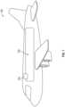
- FIG. 1 shows an aircraft 100 in an illustrative embodiment.
- the aircraft includes a cabin 102 and an air compression system 104 for pumping pressurized air into the cabin to create a safe and comfortable environment for passengers and crew flying at high altitudes.
- FIG. 2 shows the air compression system 104 in an illustrative embodiment.
- the air compression system 104 includes a compressor 202, a cooling chamber 204 for air flow to cool the compressor 202, and a power source 206.
- the compressor 202 has an air inlet 208 and an air outlet 210. Air is drawn into the compressor 202 from an environment outside of a cabin 102 of the aircraft 100 at the air inlet 208 and is pumped into the cabin at the air outlet 210.
- the cooling chamber 204 provides a volume around an outside of the compressor 202 through which air can circulate to cool the compressor 202.
- a cooling line 212 connects to the cooling chamber 204 for ingress of air for cooling ("cooling air") into the chamber.
- An exhaust line 214 connects to the cooling chamber 204 for egress of the cooling air from the cooling chamber 204.
- the cooling line 212 includes a cooling line inlet 216 that is in fluid communication with the air inlet 208.
- the cooling air is drawn from the air inlet 208 into the cooling line 212 via the cooling line inlet 216, through the cooling chamber 204, and out of the cooling chamber 204 via the exhaust line 214. From the exhaust line 214, the cooling air is released to an outside environment or exterior of the aircraft 100.
- a compressor fan 218 of the compressor 202 draws air into the compressor 202 via the air inlet 208 and forces the air out of the compressor 202 (and into the cabin 102) via the air outlet 210.
- a first motor 220 is used to operate the compressor fan 218.
- the first motor 220 can be a high-powered motor that has a power output in a range of about 100 kilowatts (kW).
- the first motor 220 is a permanent magnet motor.
- the first motor 220 draws power from the power source through an inverter 222 electrically coupled between the power source 206 and the first motor 220.
- the inverter 222 is a three-phase inverter.
- a booster fan 224 is located in either the air inlet 208 or the exhaust line 214 to generate a pressure differential (in either the air inlet 208 or the exhaust line 214) that increases airflow through the cooling chamber 204.
- the increase in airflow refers to an increase in velocity of the air in the cooling chamber 204 in comparison to the velocity of air that occurs during passive airflow.
- the increased airflow helps to circulate air for cooling the first motor 220.
- the booster fan 224 is operated using a second motor 226.
- the second motor 226 can be low power motor that has a second power output that is less than the first power output of the first motor 220.
- the second power output is in a range of about 1kW.
- the second motor is an induction motor.
- the second motor 226 draws its power from the power source 206 via the inverter 222, which is electrically coupled between the second motor 226 and the power source 206.
- a pole count and winding of the second motor 226 can be selected to obtain a selected speed for the power output of the inverter 222.
- the first motor 220 and the second motor 226 are connected to the inverter 222 in parallel.
- the first motor 220 and the second motor 226 can be turned on and off in unison via the inverter 222. Operating the first motor 220 and the second motor 226 in parallel takes advantage of the existing inverter already in the aircraft.
Landscapes
- Engineering & Computer Science (AREA)
- Mechanical Engineering (AREA)
- General Engineering & Computer Science (AREA)
- Aviation & Aerospace Engineering (AREA)
- Health & Medical Sciences (AREA)
- General Health & Medical Sciences (AREA)
- Pulmonology (AREA)
- Physics & Mathematics (AREA)
- Thermal Sciences (AREA)
- Structures Of Non-Positive Displacement Pumps (AREA)
- Compressors, Vaccum Pumps And Other Relevant Systems (AREA)
Abstract
Description
- Exemplary embodiments pertain to the art of cooling a compression system of an aircraft. Aircraft generally include compressors that are used to pressurize a cabin of the aircraft. Operation of the compressor generates heat. Thus, the compressor generally needs to be cooled. Passive cooling methods can be used to cool the compressor by directing air to flow passively around it. However, under some aircraft conditions, the passive air flow is generally inadequate to fully cool a high-powered compressor.
- According to one embodiment, a method of pressurizing a cabin of an aircraft is disclosed. A first motor of a compressor of the aircraft is operated to pressurize the cabin, wherein operation of the first motor generates heat. A second motor is operated for circulating a cooling air to cool the compressor. The first motor and the second motor are powered via an inverter.
- In addition to one or more of the features described herein, the first motor and the second motor are connected to the inverter in parallel.
- In addition to one or more of the features described herein, the method includes turning on and off the first motor and the second motor in unison.
- In addition to one or more of the features described herein, the method includes disposing the second motor in one of an air inlet of the compressor and an exhaust line of a cooling chamber of the compressor.
- In addition to one or more of the features described herein, a first power output of the first motor is greater than a second power output of the second motor.
- In addition to one or more of the features described herein, the first motor is a permanent magnet motor and the second motor is an induction motor.
- In addition to one or more of the features described herein, the second motor operates a booster fan.
- According to another embodiment, an aircraft is disclosed. The aircraft includes an air compression system for pressurizing a cabin of the aircraft. The air compression system includes a first motor for compressing air at a compressor, a second motor for circulating a cooling air to cool the compressor, and an inverter for powering the first motor and the second motor.
- In addition to one or more of the features described herein, the first motor and the second motor are connected to the inverter in parallel.
- In addition to one or more of the features described herein, the first motor and the second motor are turned on and off in unison.
- In addition to one or more of the features described herein, the compression system further includes a cooling chamber fluidly coupled to an air inlet of the compressor and having an exhaust line, wherein the second motor is located in one of the air inlet and the exhaust line.
- In addition to one or more of the features described herein, a first power output of the first motor is greater than a second power output of the second motor.
- In addition to one or more of the features described herein, the first motor is a permanent magnet motor and the second motor is an induction motor.
- In addition to one or more of the features described herein, the first motor operates a compressor fan of the compressor and the second motor operates a booster fan.
- In addition to one or more of the features described herein, wherein the inverter is a three-phase inverter.
- The following descriptions should not be considered limiting in any way. With reference to the accompanying drawings, like elements are numbered alike:
-
FIG. 1 shows an aircraft in an illustrative embodiment; and -
FIG. 2 shows the air compression system of the aircraft in an illustrative embodiment. - A detailed description of one or more embodiments of the disclosed apparatus and method are presented herein by way of exemplification and not limitation with reference to the Figures.
-
FIG. 1 shows anaircraft 100 in an illustrative embodiment. The aircraft includes acabin 102 and anair compression system 104 for pumping pressurized air into the cabin to create a safe and comfortable environment for passengers and crew flying at high altitudes. -
FIG. 2 shows theair compression system 104 in an illustrative embodiment. Theair compression system 104 includes acompressor 202, acooling chamber 204 for air flow to cool thecompressor 202, and apower source 206. Thecompressor 202 has anair inlet 208 and anair outlet 210. Air is drawn into thecompressor 202 from an environment outside of acabin 102 of theaircraft 100 at theair inlet 208 and is pumped into the cabin at theair outlet 210. The coolingchamber 204 provides a volume around an outside of thecompressor 202 through which air can circulate to cool thecompressor 202. Acooling line 212 connects to thecooling chamber 204 for ingress of air for cooling ("cooling air") into the chamber. Anexhaust line 214 connects to thecooling chamber 204 for egress of the cooling air from the coolingchamber 204. Thecooling line 212 includes a coolingline inlet 216 that is in fluid communication with theair inlet 208. The cooling air is drawn from theair inlet 208 into thecooling line 212 via the coolingline inlet 216, through thecooling chamber 204, and out of thecooling chamber 204 via theexhaust line 214. From theexhaust line 214, the cooling air is released to an outside environment or exterior of theaircraft 100. - A
compressor fan 218 of thecompressor 202 draws air into thecompressor 202 via theair inlet 208 and forces the air out of the compressor 202 (and into the cabin 102) via theair outlet 210. In various embodiments, afirst motor 220 is used to operate thecompressor fan 218. Thefirst motor 220 can be a high-powered motor that has a power output in a range of about 100 kilowatts (kW). In various embodiments, thefirst motor 220 is a permanent magnet motor. Thefirst motor 220 draws power from the power source through aninverter 222 electrically coupled between thepower source 206 and thefirst motor 220. In various embodiments, theinverter 222 is a three-phase inverter. - A
booster fan 224 is located in either theair inlet 208 or theexhaust line 214 to generate a pressure differential (in either theair inlet 208 or the exhaust line 214) that increases airflow through thecooling chamber 204. The increase in airflow refers to an increase in velocity of the air in thecooling chamber 204 in comparison to the velocity of air that occurs during passive airflow. The increased airflow helps to circulate air for cooling thefirst motor 220. Thebooster fan 224 is operated using asecond motor 226. Thesecond motor 226 can be low power motor that has a second power output that is less than the first power output of thefirst motor 220. In various embodiments, the second power output is in a range of about 1kW. In various embodiment, the second motor is an induction motor. Thesecond motor 226 draws its power from thepower source 206 via theinverter 222, which is electrically coupled between thesecond motor 226 and thepower source 206. A pole count and winding of thesecond motor 226 can be selected to obtain a selected speed for the power output of theinverter 222. - The
first motor 220 and thesecond motor 226 are connected to theinverter 222 in parallel. In various embodiments, thefirst motor 220 and thesecond motor 226 can be turned on and off in unison via theinverter 222. Operating thefirst motor 220 and thesecond motor 226 in parallel takes advantage of the existing inverter already in the aircraft. - The term "about" is intended to include the degree of error associated with measurement of the particular quantity based upon the equipment available at the time of filing the application.
- The terminology used herein is for the purpose of describing particular embodiments only and is not intended to be limiting of the present disclosure. As used herein, the singular forms "a", "an" and "the" are intended to include the plural forms as well, unless the context clearly indicates otherwise. It will be further understood that the terms "comprises" and/or "comprising," when used in this specification, specify the presence of stated features, integers, steps, operations, elements, and/or components, but do not preclude the presence or addition of one or more other features, integers, steps, operations, element components, and/or groups thereof.
- While the present disclosure has been described with reference to an exemplary embodiment or embodiments, it will be understood by those skilled in the art that various changes may be made and equivalents may be substituted for elements thereof without departing from the scope of the present disclosure. In addition, many modifications may be made to adapt a particular situation or material to the teachings of the present disclosure without departing from the essential scope thereof. Therefore, it is intended that the present disclosure not be limited to the particular embodiment disclosed as the best mode contemplated for carrying out this present disclosure, but that the present disclosure will include all embodiments falling within the scope of the claims.
Claims (15)
- A method of pressurizing a cabin of an aircraft, comprising:operating a first motor of a compressor of the aircraft to pressurize the cabin, wherein operation of the first motor generates heat;operating a second motor for circulating a cooling air to cool the compressor; andpowering the first motor and the second motor via an inverter.
- The method of claim 1, wherein the first motor and the second motor are connected to the inverter in parallel.
- The method of claim 1 or 2, further comprising turning on and off the first motor and the second motor in unison.
- The method of any preceding claim, further comprising disposing the second motor in one of an air inlet of the compressor and an exhaust line of a cooling chamber of the compressor.
- The method of any preceding claim, wherein a first power output of the first motor is greater than a second power output of the second motor.
- The method of any preceding claim, wherein the first motor is a permanent magnet motor and the second motor is an induction motor.
- The method of any preceding claim, wherein the second motor operates a booster fan.
- An aircraft, comprising:
an air compression system (104) for pressurizing a cabin of the aircraft, the air compression system comprising:a first motor (220) for compressing air at a compressor (202);a second motor (226) for circulating a cooling air to cool the compressor (202); andan inverter (222) for powering the first motor and the second motor. - The aircraft of claim 8, wherein the first motor (220) and the second motor (226) are connected to the inverter (222) in parallel.
- The aircraft of claim 8 or 9, wherein the first motor (220) and the second motor (226) are turned on and off in unison.
- The aircraft of any of claims 8-10, wherein the compression system further comprises a cooling chamber (204) fluidly coupled to an air inlet (208) of the compressor and having an exhaust line (214), wherein the second motor (226) is located in one of the air inlet (208) and the exhaust line (214).
- The aircraft of any of claims 8-11, wherein a first power output of the first motor (220) is greater than a second power output of the second motor (226).
- The aircraft of any of claims 8-12, wherein the first motor (220) is a permanent magnet motor and the second motor (226) is an induction motor.
- The aircraft of any of claims 8-13, wherein the first motor (220) operates a compressor fan of the compressor and the second motor (226) operates a booster fan.
- The aircraft of any of claims 8-14, wherein the inverter (222) is a three-phase inverter.
Applications Claiming Priority (1)
| Application Number | Priority Date | Filing Date | Title |
|---|---|---|---|
| US17/961,852 US12480527B2 (en) | 2022-10-07 | 2022-10-07 | High-power air-coooled compressor motor and low-power cooling booster fan motor powered by single inverter |
Publications (2)
| Publication Number | Publication Date |
|---|---|
| EP4349713A1 true EP4349713A1 (en) | 2024-04-10 |
| EP4349713B1 EP4349713B1 (en) | 2025-06-04 |
Family
ID=88098418
Family Applications (1)
| Application Number | Title | Priority Date | Filing Date |
|---|---|---|---|
| EP23198535.9A Active EP4349713B1 (en) | 2022-10-07 | 2023-09-20 | High-power air-cooled compressor motor and low-power cooling booster fan motor powered by single inverter |
Country Status (2)
| Country | Link |
|---|---|
| US (1) | US12480527B2 (en) |
| EP (1) | EP4349713B1 (en) |
Citations (4)
| Publication number | Priority date | Publication date | Assignee | Title |
|---|---|---|---|---|
| US6155062A (en) * | 1998-07-17 | 2000-12-05 | Eurocopter | Method of operating an air-conditioning installation of a helicopter cabin or cockpit |
| EP2407380A2 (en) * | 2010-07-16 | 2012-01-18 | Hamilton Sundstrand Corporation | Cabin air compressor motor cooling |
| EP3401223A1 (en) * | 2017-05-10 | 2018-11-14 | Hamilton Sundstrand Corporation | Motor cooling utilizing cabin air |
| EP3428069A1 (en) * | 2017-07-11 | 2019-01-16 | Hamilton Sundstrand Corporation | Cabin air compressor motor cooling flow enhancement cowl |
Family Cites Families (11)
| Publication number | Priority date | Publication date | Assignee | Title |
|---|---|---|---|---|
| US4487034A (en) * | 1981-03-27 | 1984-12-11 | Lockheed Corporation | Energy-efficient all-electric ECS for aircraft |
| US6133699A (en) | 1996-01-19 | 2000-10-17 | Gas Research Institute | Method and apparatus for operating a plurality of motors with a single controller |
| US7302804B2 (en) * | 2003-06-24 | 2007-12-04 | Honeywell International, Inc. | Cabin air compressor cooling system |
| US20050151019A1 (en) * | 2003-12-18 | 2005-07-14 | Curtis Edgar Stevens | Electrically pressurized on-board inert gas generation system |
| JP4661590B2 (en) | 2005-12-27 | 2011-03-30 | パナソニック株式会社 | Motor drive device for washing and drying machine |
| US8125164B2 (en) | 2008-07-18 | 2012-02-28 | The Boeing Company | Parallel motor controller architecture |
| GB2558228B (en) | 2016-12-22 | 2020-05-20 | Rolls Royce Plc | Aircraft electrically-assisted propulsion control system |
| US11342875B2 (en) | 2017-04-11 | 2022-05-24 | Hamilton Sundstrand Corporation | Electric motors with neutral voltage sensing |
| JP6785727B2 (en) | 2017-06-30 | 2020-11-18 | 日立ジョンソンコントロールズ空調株式会社 | Outdoor unit of air conditioner and air conditioner |
| WO2021038868A1 (en) | 2019-08-30 | 2021-03-04 | 三菱電機株式会社 | Dc power supply device, motor drive device, blower, compressor, and air conditioner |
| US11215477B2 (en) | 2020-03-11 | 2022-01-04 | Hamilton Sundstrand Corporation | Motor control systems for multiple motor drives |
-
2022
- 2022-10-07 US US17/961,852 patent/US12480527B2/en active Active
-
2023
- 2023-09-20 EP EP23198535.9A patent/EP4349713B1/en active Active
Patent Citations (4)
| Publication number | Priority date | Publication date | Assignee | Title |
|---|---|---|---|---|
| US6155062A (en) * | 1998-07-17 | 2000-12-05 | Eurocopter | Method of operating an air-conditioning installation of a helicopter cabin or cockpit |
| EP2407380A2 (en) * | 2010-07-16 | 2012-01-18 | Hamilton Sundstrand Corporation | Cabin air compressor motor cooling |
| EP3401223A1 (en) * | 2017-05-10 | 2018-11-14 | Hamilton Sundstrand Corporation | Motor cooling utilizing cabin air |
| EP3428069A1 (en) * | 2017-07-11 | 2019-01-16 | Hamilton Sundstrand Corporation | Cabin air compressor motor cooling flow enhancement cowl |
Also Published As
| Publication number | Publication date |
|---|---|
| EP4349713B1 (en) | 2025-06-04 |
| US12480527B2 (en) | 2025-11-25 |
| US20240117818A1 (en) | 2024-04-11 |
Similar Documents
| Publication | Publication Date | Title |
|---|---|---|
| US6058715A (en) | Environmental control system including air cycle machine and electrical machine | |
| US11246237B2 (en) | Ram air fan and power electronics cooling systems | |
| EP2592001B1 (en) | Turbo air compressor with pressure recovery | |
| KR100535451B1 (en) | Magnetically coupled integrated power and cooling unit | |
| EP2407380B1 (en) | Cabin air compressor motor cooling | |
| US9205925B2 (en) | Turbo air compressor | |
| US20040261428A1 (en) | Cabin air compressor cooling system | |
| CN105620756B (en) | Environmental control system using cabin air to drive power turbine of air cycle machine | |
| EP1790568A2 (en) | Cabin air conditioning system with liquid cooling for power electronics | |
| CN107303949B (en) | Environmental control system utilizing motor assisted and enhanced compressor | |
| CN108688818A (en) | Turbine assist type cabin air compressor | |
| US11578901B2 (en) | Cooling fan for refrigerant cooled motor | |
| CN107709161A (en) | Blended electric power | |
| CN104691770B (en) | On-Board Inert Gas Generating System | |
| US12480527B2 (en) | High-power air-coooled compressor motor and low-power cooling booster fan motor powered by single inverter | |
| EP3907393B1 (en) | Thermal management system and method of use | |
| EP3757389A1 (en) | Motor cooling systems | |
| US10618637B2 (en) | Motor driven cooled compressor system | |
| EP4518113A1 (en) | An air cooled electric motor having an increased airflow and a method for increasing the airflow therein | |
| US20240300547A1 (en) | Hyperloop environmental control system | |
| JP2005349912A (en) | Air conditioner for aircraft | |
| US12522259B2 (en) | Hyperloop environmental control system | |
| EP4428001A1 (en) | Hyperloop environmental control system | |
| CN110645161A (en) | Onboard miniature high-pressure compressor | |
| US20250088066A1 (en) | Airfoil fins for the passive cooling of electronic devices |
Legal Events
| Date | Code | Title | Description |
|---|---|---|---|
| PUAI | Public reference made under article 153(3) epc to a published international application that has entered the european phase |
Free format text: ORIGINAL CODE: 0009012 |
|
| STAA | Information on the status of an ep patent application or granted ep patent |
Free format text: STATUS: THE APPLICATION HAS BEEN PUBLISHED |
|
| AK | Designated contracting states |
Kind code of ref document: A1 Designated state(s): AL AT BE BG CH CY CZ DE DK EE ES FI FR GB GR HR HU IE IS IT LI LT LU LV MC ME MK MT NL NO PL PT RO RS SE SI SK SM TR |
|
| STAA | Information on the status of an ep patent application or granted ep patent |
Free format text: STATUS: REQUEST FOR EXAMINATION WAS MADE |
|
| 17P | Request for examination filed |
Effective date: 20241008 |
|
| RBV | Designated contracting states (corrected) |
Designated state(s): AL AT BE BG CH CY CZ DE DK EE ES FI FR GB GR HR HU IE IS IT LI LT LU LV MC ME MK MT NL NO PL PT RO RS SE SI SK SM TR |
|
| GRAP | Despatch of communication of intention to grant a patent |
Free format text: ORIGINAL CODE: EPIDOSNIGR1 |
|
| STAA | Information on the status of an ep patent application or granted ep patent |
Free format text: STATUS: GRANT OF PATENT IS INTENDED |
|
| INTG | Intention to grant announced |
Effective date: 20250107 |
|
| GRAS | Grant fee paid |
Free format text: ORIGINAL CODE: EPIDOSNIGR3 |
|
| GRAA | (expected) grant |
Free format text: ORIGINAL CODE: 0009210 |
|
| STAA | Information on the status of an ep patent application or granted ep patent |
Free format text: STATUS: THE PATENT HAS BEEN GRANTED |
|
| AK | Designated contracting states |
Kind code of ref document: B1 Designated state(s): AL AT BE BG CH CY CZ DE DK EE ES FI FR GB GR HR HU IE IS IT LI LT LU LV MC ME MK MT NL NO PL PT RO RS SE SI SK SM TR |
|
| REG | Reference to a national code |
Ref country code: GB Ref legal event code: FG4D |
|
| REG | Reference to a national code |
Ref country code: CH Ref legal event code: EP |
|
| REG | Reference to a national code |
Ref country code: DE Ref legal event code: R096 Ref document number: 602023003823 Country of ref document: DE |
|
| REG | Reference to a national code |
Ref country code: IE Ref legal event code: FG4D |
|
| REG | Reference to a national code |
Ref country code: NL Ref legal event code: MP Effective date: 20250604 |
|
| PG25 | Lapsed in a contracting state [announced via postgrant information from national office to epo] |
Ref country code: FI Free format text: LAPSE BECAUSE OF FAILURE TO SUBMIT A TRANSLATION OF THE DESCRIPTION OR TO PAY THE FEE WITHIN THE PRESCRIBED TIME-LIMIT Effective date: 20250604 Ref country code: ES Free format text: LAPSE BECAUSE OF FAILURE TO SUBMIT A TRANSLATION OF THE DESCRIPTION OR TO PAY THE FEE WITHIN THE PRESCRIBED TIME-LIMIT Effective date: 20250604 |
|
| REG | Reference to a national code |
Ref country code: LT Ref legal event code: MG9D |
|
| PG25 | Lapsed in a contracting state [announced via postgrant information from national office to epo] |
Ref country code: GR Free format text: LAPSE BECAUSE OF FAILURE TO SUBMIT A TRANSLATION OF THE DESCRIPTION OR TO PAY THE FEE WITHIN THE PRESCRIBED TIME-LIMIT Effective date: 20250905 Ref country code: NO Free format text: LAPSE BECAUSE OF FAILURE TO SUBMIT A TRANSLATION OF THE DESCRIPTION OR TO PAY THE FEE WITHIN THE PRESCRIBED TIME-LIMIT Effective date: 20250904 |
|
| PG25 | Lapsed in a contracting state [announced via postgrant information from national office to epo] |
Ref country code: PL Free format text: LAPSE BECAUSE OF FAILURE TO SUBMIT A TRANSLATION OF THE DESCRIPTION OR TO PAY THE FEE WITHIN THE PRESCRIBED TIME-LIMIT Effective date: 20250604 |
|
| PG25 | Lapsed in a contracting state [announced via postgrant information from national office to epo] |
Ref country code: BG Free format text: LAPSE BECAUSE OF FAILURE TO SUBMIT A TRANSLATION OF THE DESCRIPTION OR TO PAY THE FEE WITHIN THE PRESCRIBED TIME-LIMIT Effective date: 20250604 |
|
| PG25 | Lapsed in a contracting state [announced via postgrant information from national office to epo] |
Ref country code: HR Free format text: LAPSE BECAUSE OF FAILURE TO SUBMIT A TRANSLATION OF THE DESCRIPTION OR TO PAY THE FEE WITHIN THE PRESCRIBED TIME-LIMIT Effective date: 20250604 |
|
| PGFP | Annual fee paid to national office [announced via postgrant information from national office to epo] |
Ref country code: FR Payment date: 20250820 Year of fee payment: 3 Ref country code: AT Payment date: 20251020 Year of fee payment: 3 |
|
| PG25 | Lapsed in a contracting state [announced via postgrant information from national office to epo] |
Ref country code: RS Free format text: LAPSE BECAUSE OF FAILURE TO SUBMIT A TRANSLATION OF THE DESCRIPTION OR TO PAY THE FEE WITHIN THE PRESCRIBED TIME-LIMIT Effective date: 20250904 |
|
| PG25 | Lapsed in a contracting state [announced via postgrant information from national office to epo] |
Ref country code: LV Free format text: LAPSE BECAUSE OF FAILURE TO SUBMIT A TRANSLATION OF THE DESCRIPTION OR TO PAY THE FEE WITHIN THE PRESCRIBED TIME-LIMIT Effective date: 20250604 |
|
| PG25 | Lapsed in a contracting state [announced via postgrant information from national office to epo] |
Ref country code: NL Free format text: LAPSE BECAUSE OF FAILURE TO SUBMIT A TRANSLATION OF THE DESCRIPTION OR TO PAY THE FEE WITHIN THE PRESCRIBED TIME-LIMIT Effective date: 20250604 |
|
| PG25 | Lapsed in a contracting state [announced via postgrant information from national office to epo] |
Ref country code: PT Free format text: LAPSE BECAUSE OF FAILURE TO SUBMIT A TRANSLATION OF THE DESCRIPTION OR TO PAY THE FEE WITHIN THE PRESCRIBED TIME-LIMIT Effective date: 20251006 |
|
| REG | Reference to a national code |
Ref country code: AT Ref legal event code: MK05 Ref document number: 1800149 Country of ref document: AT Kind code of ref document: T Effective date: 20250604 |
|
| PG25 | Lapsed in a contracting state [announced via postgrant information from national office to epo] |
Ref country code: IS Free format text: LAPSE BECAUSE OF FAILURE TO SUBMIT A TRANSLATION OF THE DESCRIPTION OR TO PAY THE FEE WITHIN THE PRESCRIBED TIME-LIMIT Effective date: 20251004 |
|
| PG25 | Lapsed in a contracting state [announced via postgrant information from national office to epo] |
Ref country code: SM Free format text: LAPSE BECAUSE OF FAILURE TO SUBMIT A TRANSLATION OF THE DESCRIPTION OR TO PAY THE FEE WITHIN THE PRESCRIBED TIME-LIMIT Effective date: 20250604 Ref country code: AT Free format text: LAPSE BECAUSE OF FAILURE TO SUBMIT A TRANSLATION OF THE DESCRIPTION OR TO PAY THE FEE WITHIN THE PRESCRIBED TIME-LIMIT Effective date: 20250604 |
|
| PG25 | Lapsed in a contracting state [announced via postgrant information from national office to epo] |
Ref country code: CZ Free format text: LAPSE BECAUSE OF FAILURE TO SUBMIT A TRANSLATION OF THE DESCRIPTION OR TO PAY THE FEE WITHIN THE PRESCRIBED TIME-LIMIT Effective date: 20250604 |
|
| PG25 | Lapsed in a contracting state [announced via postgrant information from national office to epo] |
Ref country code: EE Free format text: LAPSE BECAUSE OF FAILURE TO SUBMIT A TRANSLATION OF THE DESCRIPTION OR TO PAY THE FEE WITHIN THE PRESCRIBED TIME-LIMIT Effective date: 20250604 |
|
| PG25 | Lapsed in a contracting state [announced via postgrant information from national office to epo] |
Ref country code: SK Free format text: LAPSE BECAUSE OF FAILURE TO SUBMIT A TRANSLATION OF THE DESCRIPTION OR TO PAY THE FEE WITHIN THE PRESCRIBED TIME-LIMIT Effective date: 20250604 |
|
| PG25 | Lapsed in a contracting state [announced via postgrant information from national office to epo] |
Ref country code: IT Free format text: LAPSE BECAUSE OF FAILURE TO SUBMIT A TRANSLATION OF THE DESCRIPTION OR TO PAY THE FEE WITHIN THE PRESCRIBED TIME-LIMIT Effective date: 20250604 |
|
| REG | Reference to a national code |
Ref country code: DE Ref legal event code: R097 Ref document number: 602023003823 Country of ref document: DE |
|
| PG25 | Lapsed in a contracting state [announced via postgrant information from national office to epo] |
Ref country code: RO Free format text: LAPSE BECAUSE OF FAILURE TO SUBMIT A TRANSLATION OF THE DESCRIPTION OR TO PAY THE FEE WITHIN THE PRESCRIBED TIME-LIMIT Effective date: 20250604 |
|
| PLBE | No opposition filed within time limit |
Free format text: ORIGINAL CODE: 0009261 |
|
| STAA | Information on the status of an ep patent application or granted ep patent |
Free format text: STATUS: NO OPPOSITION FILED WITHIN TIME LIMIT |
|
| PG25 | Lapsed in a contracting state [announced via postgrant information from national office to epo] |
Ref country code: DK Free format text: LAPSE BECAUSE OF FAILURE TO SUBMIT A TRANSLATION OF THE DESCRIPTION OR TO PAY THE FEE WITHIN THE PRESCRIBED TIME-LIMIT Effective date: 20250604 |
|
| REG | Reference to a national code |
Ref country code: CH Ref legal event code: L10 Free format text: ST27 STATUS EVENT CODE: U-0-0-L10-L00 (AS PROVIDED BY THE NATIONAL OFFICE) Effective date: 20260416 |
|
| 26N | No opposition filed |
Effective date: 20260305 |