EP4349707A1 - Vessel navigation assistance device, vessel navigation assistance method, and vessel navigation assistance program - Google Patents
Vessel navigation assistance device, vessel navigation assistance method, and vessel navigation assistance program Download PDFInfo
- Publication number
- EP4349707A1 EP4349707A1 EP22810911.2A EP22810911A EP4349707A1 EP 4349707 A1 EP4349707 A1 EP 4349707A1 EP 22810911 A EP22810911 A EP 22810911A EP 4349707 A1 EP4349707 A1 EP 4349707A1
- Authority
- EP
- European Patent Office
- Prior art keywords
- ship
- reference point
- quay
- side reference
- distance
- Prior art date
- Legal status (The legal status is an assumption and is not a legal conclusion. Google has not performed a legal analysis and makes no representation as to the accuracy of the status listed.)
- Pending
Links
Images






Classifications
-
- B—PERFORMING OPERATIONS; TRANSPORTING
- B63—SHIPS OR OTHER WATERBORNE VESSELS; RELATED EQUIPMENT
- B63B—SHIPS OR OTHER WATERBORNE VESSELS; EQUIPMENT FOR SHIPPING
- B63B79/00—Monitoring properties or operating parameters of vessels in operation
- B63B79/10—Monitoring properties or operating parameters of vessels in operation using sensors, e.g. pressure sensors, strain gauges or accelerometers
-
- G—PHYSICS
- G01—MEASURING; TESTING
- G01C—MEASURING DISTANCES, LEVELS OR BEARINGS; SURVEYING; NAVIGATION; GYROSCOPIC INSTRUMENTS; PHOTOGRAMMETRY OR VIDEOGRAMMETRY
- G01C9/00—Measuring inclination, e.g. by clinometers, by levels
-
- G—PHYSICS
- G01—MEASURING; TESTING
- G01S—RADIO DIRECTION-FINDING; RADIO NAVIGATION; DETERMINING DISTANCE OR VELOCITY BY USE OF RADIO WAVES; LOCATING OR PRESENCE-DETECTING BY USE OF THE REFLECTION OR RERADIATION OF RADIO WAVES; ANALOGOUS ARRANGEMENTS USING OTHER WAVES
- G01S17/00—Systems using the reflection or reradiation of electromagnetic waves other than radio waves, e.g. lidar systems
- G01S17/88—Lidar systems specially adapted for specific applications
- G01S17/93—Lidar systems specially adapted for specific applications for anti-collision purposes
-
- G—PHYSICS
- G08—SIGNALLING
- G08G—TRAFFIC CONTROL SYSTEMS
- G08G3/00—Traffic control systems for marine craft
- G08G3/02—Anti-collision systems
-
- B—PERFORMING OPERATIONS; TRANSPORTING
- B63—SHIPS OR OTHER WATERBORNE VESSELS; RELATED EQUIPMENT
- B63B—SHIPS OR OTHER WATERBORNE VESSELS; EQUIPMENT FOR SHIPPING
- B63B21/00—Tying-up; Shifting, towing, or pushing equipment; Anchoring
- B63B2021/003—Mooring or anchoring equipment, not otherwise provided for
Definitions
- the present disclosure relates to a navigation support technique, for example, used when anchoring a ship.
- Berthing support devices which measure a distance between a ship and an object, such as a quay, using a distance sensor are known.
- the distance between the ship and the object may not be measured with sufficient accuracy.
- one purpose of the present disclosure is to measure a distance between a ship and an object with more sufficient accuracy.
- a navigation support device includes a distance measuring part, a posture measuring part, a ship-side reference point setting part, and a horizontal distance calculating part.
- the distance measuring part measures a distance of a quay that is a target at which a ship docks, on the basis of a ranging coordinate system, and outputs ranging information on the quay on the basis of the ranging coordinate system.
- the posture measuring part measures a posture of the ship.
- the ship-side reference point setting part sets a given position of the ship as a ship-side reference point on the basis of the ranging coordinate system.
- the horizontal distance calculating part calculates a horizontal distance between the ship and the quay based on the ranging information on the quay and the ship-side reference point that are projected to a horizontal plane, by using the posture.
- the horizontal distance calculating part may include a projecting part, a quay line extracting part, and a distance calculating part.
- the projecting part projects the ranging information on the quay and the ship-side reference point to the horizontal plane by using the posture.
- the quay line extracting part extracts a quay line for calculation of the horizontal distance based on the ranging information on the quay projected to the horizontal plane.
- the distance calculating part calculates the horizontal distance based on the quay line and the ship-side reference point.
- the posture may include a rolling component.
- the posture may include a yawing component.
- the ship-side reference point setting part may set a plurality of the ship-side reference points.
- the horizontal distance calculating part may calculate the horizontal distance at an arbitrary measurement reference point on a straight line passing through the plurality of ship-side reference points based on the horizontal distances of the plurality of ship-side reference points.
- the navigation support device of the present disclosure may include a draft measuring part which measures a draft of the ship.
- the ship-side reference point setting part may set a position of the ship-side reference point in a height direction of the ship based on the draft.
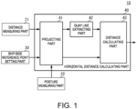
- FIG. 1 is a functional block diagram illustrating a configuration of a navigation support device according to a first embodiment of the present disclosure.
- Figs. 2(A) and 2(B) are side views illustrating a spatial relationship between a ship, a distance measuring part, a quay, and a ship-side reference point.
- Fig. 2(A) illustrates a state where shaking in the rolling direction (rolling) does not occur
- a navigation support device 10 includes a distance measuring part 21, a posture measuring part 22, a ship-side reference point setting part 30, and a horizontal distance calculating part 40.
- the navigation support device 10 is realizable, except for the optical system and the radio wave system, by a navigation support program which realizes a navigation support method, a memory device which stores the navigation support program, and a processor, such as a CPU, which executes the navigation support program. Further, the memory device and the processor may also be realized by an IC in which the navigation support program is incorporated.
- the distance measuring part 21 is a distance measuring or ranging device, such as a LiDAR.
- the distance measuring part 21 transmits a detection wave within a three-dimensional detection area, and generates ranging information from a reception signal thereof.
- the distance measuring part 21 detects a signal level of a reflection wave, and extracts a point (position), at which a reflection wave above a given signal level is obtained, as a characteristic point.
- the distance measuring part 21 uses position coordinates of the characteristic point expressed by a three-dimensional ranging coordinate system as ranging information.
- the position coordinates of the characteristic point can be calculated based on an incoming direction of the reflection wave of the detection wave, and a half of a time difference between a transmission timing of the detection wave and a reception timing of the reflection wave.
- the distance measuring part 21 is installed near an upper end of a ship 80 on the port side.
- the distance measuring part 21 has xs coordinate axis, ys coordinate axis, and zs coordinate axis of the three-dimensional ranging coordinate system.
- the distance measuring part 21 is installed in a given posture with respect to the ship 80.
- a three-dimensional ship body coordinate system is set as the ship 80, and it has xb coordinate axis, yb coordinate axis, and zb coordinate axis.
- the xb coordinate axis is parallel to the bow-and-stem direction of the ship 80, the bow direction is set as positive (+) direction, and the stem direction is set as negative (-) direction.
- the yb coordinate axis is parallel to the width direction (the starboard-and-port direction) of the ship 80, the port direction is set as + direction, and the starboard direction is set as - direction.
- the zb coordinate axis is parallel to the height direction of the ship 80, upward is set as + direction, and downward is set as - direction. Note that this setup is one example and it is not limited to this configuration.
- the distance measuring part 21 is installed so that the xs coordinate axis is parallel to the xb coordinate axis, and their + directions are in agreement with each other.
- the distance measuring part 21 is installed so that the ys coordinate axis is parallel to the yb coordinate axis, and their + directions are in agreement with each other.
- the distance measuring part 21 is installed so that the zs coordinate axis is parallel to the zb coordinate axis, and their + directions are opposite from each other.
- this spatial relationship between the ranging coordinate system and the ship body coordinate system is also one example, and it is not limited to this configuration, as long as the angle differences (formed angle) of coordinate axes of each coordinate system are defined and recognized uniquely.
- the distance measuring part 21 can extract the characteristic point in the three-dimensional area in the bow-and-stem direction (the direction parallel to the xb coordinate axis), the starboard-and-port direction (the direction parallel to the yb coordinate axis), and the height direction of the ship 80 (the direction parallel to the zb coordinate axis), on the port side of the ship 80. Further, the distance measuring part 21 acquires position coordinates in the ranging coordinate system of the characteristic point, and generates the ranging information. The distance measuring part 21 outputs the ranging information to the horizontal distance calculating part 40.
- the posture measuring part 22 is realized, for example, by an attitude sensor provided to the ship 80.
- the attitude sensor may use a positioning technique of GNSS signals, or may use an inertia sensor. Further, the attitude sensor may combine the positioning technique of the GNSS signals and the inertia sensor. If the positioning technique of the GNSS signals is used, the position (position coordinates) of the ship can also be measured. Further, if the positioning technique of the GNSS signals is used, the attitude angle can be measured with high precision under an open sky environment like on the ocean.
- the posture measuring part 22 is installed at substantially the same position as the distance measuring part 21 with respect to the ship 80.
- the posture measuring part 22 is preferred to be installed so that the coordinate system of the attitude angle to be measured becomes in agreement with the ranging coordinate system.
- similar effects can be acquired by acquiring the angle difference between the coordinate system of the posture measuring part 22 and the ranging coordinate system beforehand, and performing correction using this angle difference.
- the posture measuring part 22 measures the attitude angle of the ship 80.
- the attitude angle measured by the posture measuring part 22 can be expressed by an angle variation in each coordinate axis of the ship body coordinate system and the ranging coordinate system with respect to the absolute coordinate system, when the state changes to the state where the ship 80 is shaking from the state where the ship 80 is not shaking.
- the absolute coordinate system in this embodiment is the coordinate system defined with perpendicularly-crossed coordinate axes which do not change with movement and displacement of the ship 80, and the position coordinates of the absolute coordinate system of a quay 90 which is not influenced by the movement and the displacement of the ship 80 do not change.
- Fig. 2(A) it is set by the xa coordinate axis and the ya coordinate axis which are perpendicularly-crossed two axes parallel to a water surface WS (more precisely, the water surface WS in a still water state where wave is not produced), and the za coordinate axis perpendicular to the water surface WS. Note that, although in Figs.
- the direction parallel to a quay line 900 is the xa coordinate axis and the direction perpendicular to the quay line 900 is the ya coordinate axis in order to simplify the explanation, it is not limited to this configuration.
- the posture measuring part 22 measures the attitude angle ⁇ in the rolling direction of the ship 80, the attitude angle in the pitching direction of the ship 80, and the attitude angle in the yawing direction of the ship 80. Note that, in this embodiment, the posture measuring part 22 is not limited as long as it can measure at least the attitude angle ⁇ in the rolling direction of the ship 80.
- the posture measuring part 22 outputs the measured attitude angle(s) to the horizontal distance calculating part 40.
- the ship-side reference point setting part 30 sets a ship-side reference point 800.
- the ship-side reference point 800 is a reference point which is set to the ship 80 in order to calculate a horizontal distance described later.
- the ship-side reference point setting part 30 sets the ship-side reference point 800, for example, at a position of a given height on the port side surface of the ship 80, as illustrated in Figs. 2(A) and 2(B) .
- the position of the ship-side reference point 800 is set, for example, at a position of the substantially same height as the water surface WS during normal operation of the ship 80.
- the position coordinates of the ship-side reference point 800 are set as follows, for example.
- a reflector etc. is installed beforehand at a location which will be at the water surface WS.
- the distance measuring part 21 detects this reflector, and calculates the position coordinates in the ranging coordinate system.
- the ship-side reference point setting part 30 sets the position coordinates as position coordinates of the ship-side reference point 800.
- the ship-side reference point setting part 30 outputs the position coordinates of the ship-side reference point 800 to the horizontal distance calculating part 40.
- the horizontal distance calculating part 40 includes a projecting part 41, a quay line extracting part 42, and a distance calculating part 43.
- the position coordinates (the ranging information) of each characteristic point obtained on the basis of the ranging coordinate system, the position coordinates of the ship-side reference point 800 set on the basis of the ranging coordinate system, and the attitude angle measured by the posture measuring part 22 are inputted into the projecting part 41.
- the projecting part 41 projects the position coordinates of each characteristic point and the position coordinates of the ship-side reference point 800 to a horizontal plane using the attitude angle. That is, the projecting part 41 calculates the position coordinates of each characteristic point (projected position coordinates of each characteristic point) and the position coordinates of the ship-side reference point 800 (projected position coordinates of the ship-side reference point 800) which are defined on the basis of the absolute coordinate system and are projected to the horizontal plane.
- the projecting part 41 calculates the projected position coordinates of each characteristic point and the projected position coordinates of the ship-side reference point 800 using the attitude angle ⁇ in the rolling direction.
- Figs. 3(A) and 3(B) are views illustrating one example of the spatial relationship between the ship-side reference point and the quay line after the projection to the horizontal plane.
- Fig. 3(A) illustrates a state where shaking in the rolling direction does not occur similarly to Fig. 2(A)
- Fig. 3(B) illustrates a state where shaking in the rolling direction occurs (the attitude angle ⁇ in the rolling direction) similarly to Fig. 2(B) .
- the projecting part 41 outputs the projected position coordinates of each characteristic point to the quay line extracting part 42. Further, the projecting part 41 outputs the projected position coordinates of the ship-side reference point 800 to the distance calculating part 43.
- the quay line extracting part 42 extracts the quay line 900 from the projected position coordinates of a plurality of characteristic points. For example, the quay line extracting part 42 detects a plurality of characteristic points, which are lined up on a substantially straight line, from the projected position coordinates of the plurality of characteristic points. The quay line extracting part 42 calculates a line segment which connects the plurality of characteristic points lined up on the substantially straight line as a vector quantity. The quay line extracting part 42 extracts the line segment expressed by the vector quantity as the quay line 900.
- the quay line extracting part 42 calculates the line segment expressed by the vector quantity for every straight line.
- the quay line extracting part 42 uses a statistical procedure (for example, a maximum likelihood method) etc. for the plurality of line segments to extract one quay line 900 which is comprised of the line segment expressed by the vector quantity.
- the quay line extracting part 42 outputs the quay line 900 of the vector quantity to the distance calculating part 43.
- the distance calculating part 43 calculates a horizontal distance L89 by using the quay line 900 of the vector quantity, and the projected position coordinates of the ship-side reference point 800. For example, the distance calculating part 43 calculates the horizontal distance L89 by using a formula for a distance between the vector (straight line) and the point. If this is illustrated conceptionally, as illustrated in Figs. 3(A) and 3(B) , the distance calculating part 43 uses the foot of a perpendicular line from the ship-side reference point 800 to the quay line 900 as a quay reference point 901, and calculates the horizontal distance L89 which is the distance between the ship-side reference point 800 and the quay reference point 901.
- a horizontal distance L89n becomes a value obtained by adding a distance L90n between the distance measuring part 21 and the quay reference point 901 (the quay line 900) which are projected to the horizontal plane, to a distance L80n between the distance measuring part 21 and the ship-side reference point 800 which are projected to the horizontal plane.
- a horizontal distance L89r becomes a value obtained by adding a distance L90r between the distance measuring part 21 and the quay reference point 901 (the quay line 900) which are projected to the horizontal plane, to a distance L80r between the distance measuring part 21 and the ship-side reference point 800 which are projected to the horizontal plane.
- the quay line 900 (the quay reference point 901) is not influenced by the shaking of the ship 80 in the absolute coordinate system, and thereby, the position coordinates do not change.
- the position coordinates (the ranging information) of the quay line 900 (the quay reference point 901) in the ranging coordinate system changes according to a magnitude of the shaking.
- the distance L90n between the quay line 900 (the quay reference point 901) and the distance measuring part 21 in the horizontal plane when shaking does not occur, and the distance L90r between the quay line 900 (the quay reference point 901) and the distance measuring part 21 in the horizontal plane when shaking occurs changes according to the magnitude of shaking.
- the horizontal distance when shaking does not occur and the horizontal distance when shaking occurs differ from each other according to the magnitude of shaking. That is, the horizontal distance includes error due to shaking.
- the ship-side reference point 800 is set on the basis of the ranging coordinate system.
- the position coordinates of the ship-side reference point 800 on the basis of the ranging coordinate system do not change according to the magnitude of shaking. That is, the position coordinates of the ship-side reference point 800 on the basis of the ranging coordinate system do not change regardless of the existence of shaking.
- the relationship between the absolute coordinate system and the ranging coordinate system changes.
- the distance L80n between the quay line 900 (the quay reference point 901) and the distance measuring part 21 in the horizontal plane when shaking does not occur, and the distance L80r between the ship-side reference point 800 and the distance measuring part 21 in the horizontal plane when shaking occurs change according to the magnitude of shaking.
- a direction of the change in the quay line 900 (the quay reference point 901) with respect to the distance measuring part 21 becomes the same as a direction of the change in the ship-side reference point 800 with respect to the distance measuring part 21.
- the quay line 900 (the quay reference point 901) and the ship-side reference point 800 change in the same direction.
- the navigation support device 10 can suppress the influence of the shaking of the ship 80 to measure the horizontal distance between the ship 80 and the quay line 900 with more sufficient accuracy.
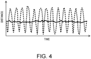
- Fig. 4 is a graph illustrating one example of the change in the horizontal distance between the case where shaking occurs and the case where shaking does not occur.
- Fig. 4 is a graph which is created by simulating the shaking.
- a solid line illustrates a case where the configuration and the processing of the present disclosure are used, and a broken line illustrates a case where the configuration and the processing of the present disclosure are not adopted (for example, when the horizontal distance between the distance measuring part 21 and the quay line 900 (the quay reference point 901) is used as it is).
- the navigation support device 10 can measure the horizontal distance between the ship 80 and the quay line 900 with more sufficient accuracy.
- Fig. 5 is a flowchart illustrating one example of a navigation support method according to a first embodiment of the present disclosure.
- Fig. 6 is a flowchart illustrating one example where a calculation of the horizontal distance illustrated in Fig. 5 is implemented. Note that, since the details of each processing illustrated in Figs. 5 and 6 are explained as the navigation support device 10 described above, explanation is omitted below unless there is necessity for additional explanation.
- the distance measuring part 21 of the navigation support device 10 measures a distance around the ship 80 (in the case of Figs. 2(A) and 2(B) , on the port side of the ship 80) on the basis of the ranging coordinate system (S11).
- the posture measuring part 22 of the navigation support device 10 measures the posture of the ship 80 (S 12).
- the ship-side reference point setting part 30 of the navigation support device 10 sets the ship-side reference point 800 on the basis of the ranging coordinate system.
- the horizontal distance calculating part 40 of the navigation support device 10 calculates the horizontal distance between the ship 80 and the quay 90 (the quay line 900) based on the posture, the quay line according to the ranging information acquired by the ranging, and the ship-side reference point (S14).
- the projecting part 41 of the horizontal distance calculating part 40 projects the characteristic point included in the ranging information, and the ship-side reference point to the horizontal plane by using the posture (S41).
- the quay line extracting part 42 extracts the quay line 900 from a plurality of characteristic points projected to the horizontal plane (S42).
- the distance calculating part 43 calculates the horizontal distance based on the quay line 900 (vector quantity) and the position coordinates of the ship-side reference point 800 in the horizontal plane (S43).
- the horizontal distance between the ship 80 and the quay line 900 can be measured with more sufficient accuracy, while suppressing the influence of shaking.
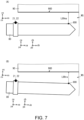
- FIGs. 7(A) and 7(B) are plan views illustrating a spatial relationship between the ship, the distance measuring part, the quay, and the ship-side reference point.
- Fig. 7(A) illustrates a state where shaking in the yawing direction at the stem does not occur
- Fig. 7(B) illustrates a state where shaking in the yawing direction at the stem occurs (the attitude-angle in the yawing direction # 0°).
- a navigation support device is the same in the configuration in terms of the functional blocks as the navigation support device 10 according to the first embodiment, but differs in that it suppresses the influence of shaking in the rolling direction and shaking in the yawing direction.
- the distance measuring part 21 and the posture measuring part 22 are installed near the stem of the ship 80.
- the ship-side reference point setting part 30 sets the ship-side reference point 800 near the water surface WS near the bow.
- the posture measuring part 22 measures at least the attitude angle in the yawing direction of the ship 80.
- the navigation support device according to the second embodiment can suppress the influence of shaking, and can measure the horizontal distance between the bow of the ship 80 and the quay line 900 with more sufficient accuracy.
- the navigation support device can suppress the influences of shaking in the rolling direction and shaking in the yawing direction, and can measure the horizontal distance between the bow of the ship 80 and the quay line 900 with still more sufficient accuracy.
- FIG. 8 is a functional block diagram illustrating a configuration of a navigation support device according to the third embodiment of the present disclosure.
- Fig. 9 is a plan view illustrating a spatial relationship between the ship, the distance measuring part, the quay, and the ship-side reference point.
- a navigation support device 10A according to the third embodiment differs from the navigation support device according to the second embodiment in that a plurality of ship-side reference points are set, and a measurement reference point is set, and also differs in the configuration and the processing of a horizontal distance calculating part 40A.
- Other configurations and processings of the navigation support device 10A according to the third embodiment are similar to those of the navigation support device according to the second embodiment, and therefore, explanation of similar parts is omitted.
- the navigation support device 10A includes the distance measuring part 21, the posture measuring part 22, a ship-side reference point setting part 30A, a measurement reference point setting part 31, and the horizontal distance calculating part 40A.
- the horizontal distance calculating part 40A includes the projecting part 41, the quay line extracting part 42, a distance calculating part 43A, and a distance ratio calculating part 44.
- the ship-side reference point setting part 30A sets a ship-side reference point 801 and a ship-side reference point 802 along the port side of the ship 80.
- the number of ship-side reference points which are set may be three or more.
- the measurement reference point setting part 31 receives an operation input from a user etc., and sets an arbitrary position along the port side of the ship 80 as a measurement reference point 803. In other words, the measurement reference point setting part 31 sets an arbitrary point (position) on a straight line which connects the ship-side reference point 801 with the ship-side reference point 802 as the measurement reference point 803.
- the measurement reference point 803 is set between the ship-side reference point 801 and the ship-side reference point 802. However, the measurement reference point 803 may be set at a position not between the ship-side reference point 801 and the ship-side reference point 802.
- the projecting part 41 projects the position coordinates of the characteristic point of the quay 90 which is the ranging information, position coordinates of the ship-side reference point 801, position coordinates of the ship-side reference point 802, and position coordinates of the measurement reference point 803 to the horizontal plane.
- the projecting part 41 calculates position coordinates of each characteristic point projected to the horizontal plane defined by the absolute coordinate system (projected position coordinates of each characteristic point), which are position coordinates of the ship-side reference points 801 and 802 (projected position coordinates of the ship-side reference points 801 and 802), and position coordinates of the measurement reference point 803 (projected position coordinates of the measurement reference point 803).
- the projecting part 41 outputs the position coordinates of the ship-side reference points 801 and 802 (the projected position coordinates of the ship-side reference points 801 and 802), and the position coordinates of the measurement reference point 803 (the projected position coordinates of the measurement reference point 803) to the distance ratio calculating part 44.
- the distance ratio calculating part 44 calculates a horizontal distance LL31 between the ship-side reference point 801 and the measurement reference point 803 in the horizontal plane, and a horizontal distance LL32 between the ship-side reference point 802 and the measurement reference point 803.
- the distance ratio calculating part 44 calculates a distance ratio of the horizontal distance LL31 and the horizontal distance LL32.
- the distance ratio calculating part 44 outputs the distance ratio to the distance calculating part 43A.
- the distance calculating part 43A calculates, by using a similar method to the distance calculating part 43, a horizontal distance L891 of the ship-side reference point 801, and a horizontal distance L892 of the ship-side reference point 802.
- the distance calculating part 43A calculates a horizontal distance L893 at the position of the measurement reference point 803 based on the horizontal distance L891, the horizontal distance L892, and the distance ratio of the horizontal distance LL31 and the horizontal distance LL32.
- the navigation support device 10A can calculate the horizontal distance to the quay line 900 from the arbitrary position of the ship 80. Further, since the horizontal distances at the plurality of ship-side reference points 801 and 802 are used for the calculation of the horizontal distance, the navigation support device 10A can suppress the influence of shaking, and can measure the horizontal distance between the ship 80 and the quay line 900 at the arbitrary position with more sufficient accuracy.
- Fig. 10 is a flowchart illustrating one example of a navigation support method according to the third embodiment of the present disclosure. Note that, since the details of each processing illustrated in Fig. 10 are explained as the navigation support device 10A described above, explanation is omitted below unless there is necessity for additional explanation. Further, below, explanation of similar parts to the flowchart illustrated in Figs. 5 and 6 is omitted.
- the ship-side reference point setting part 30A sets the plurality of ship-side reference points on the basis of the ranging coordinate system (S 13A).
- the measurement reference point setting part 31 sets the measurement reference point on the basis of the ranging coordinate system (S21).
- the distance ratio calculating part 44 calculates the distance ratio of each ship-side reference point and the measurement reference point (S22).
- the distance calculating part 43A calculates the horizontal distances at the plurality of ship-side reference points (S45). The distance calculating part 43A calculates the horizontal distance at the measurement reference point based on the horizontal distances of the plurality of ship-side reference points and the distance ratios (S46).
- the horizontal distance between the ship 80 and the quay line 900 at the arbitrary position can be measured with more sufficient accuracy, while suppressing the influence of shaking.
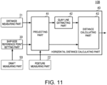
- FIG. 11 is a functional block diagram illustrating a configuration of a navigation support device according to the fourth embodiment of the present disclosure.
- a navigation support device 10B according to the fourth embodiment differs from the navigation support device 10 according to the first embodiment in that it is provided with a draft measuring part 50.
- the navigation support device 10B is provided with the draft measuring part 50.
- the draft measuring part 50 is installed in the ship 80 to measure the draft at the installed position of the ship-side reference point in the bow-and-stem direction of the ship 80.
- As the measuring method of the draft a known method is used.
- the draft measuring part 50 measures the draft of the ship 80, and outputs it to the ship-side reference point setting part 30.
- the ship-side reference point setting part 30 sets the position of the ship-side reference point in the height direction of the ship 80 according to the draft. For example, in detail, the ship-side reference point is set at a plurality of positions of the ship 80 in the height direction.
- the ship-side reference point setting part 30 selects a ship-side reference point nearest to the water surface WS according to the draft.
- the ship-side reference point setting part 30 outputs the position coordinates of the selected ship-side reference point to the projecting part 41.
- the navigation support device 10B can set the suitable ship-side reference point according to the draft. Therefore, the navigation support device 10B can measure the horizontal distance with more sufficient accuracy.
- Fig. 12 is a flowchart illustrating one example of a navigation support method according to the fourth embodiment of the present disclosure. Note that, since the details of each processing illustrated in Fig. 12 are explained as the navigation support device 10 described above, explanation is omitted below unless there is necessity for additional explanation. Further, below, explanation of similar parts to the flowchart illustrated in Fig. 5 is omitted.
- the draft measuring part 50 measures the draft of the ship 80 (S51).
- the ship-side reference point setting part 30 sets the ship-side reference point on the basis of the ranging coordinate system based on the draft (S13B).
- the horizontal distance between the ship 80 and the quay line 900 can be measured with more sufficient accuracy corresponding to the draft, while suppressing the influence of shaking.
- the ship 80 docks at the quay 90 on the port side.
- the configuration and processing described above are also applicable when docking the ship 80 at the quay 90 on the starboard side.
- the distance measuring part 21 is installed on the starboard side of the ship 80.
- a quay is a target.
- the configuration and processing described above are applicable, as long as it is an object at which the ship docks or anchors, such as a pier and another ship.
- the straight line (line segment) is used as the characteristic information.
- a point, a surface, and a curve may also be used as the characteristic information, and the configuration and processing described above may also be applicable to these cases.
Landscapes
- Engineering & Computer Science (AREA)
- Physics & Mathematics (AREA)
- General Physics & Mathematics (AREA)
- Radar, Positioning & Navigation (AREA)
- Remote Sensing (AREA)
- Ocean & Marine Engineering (AREA)
- Chemical & Material Sciences (AREA)
- Combustion & Propulsion (AREA)
- Mechanical Engineering (AREA)
- Computer Networks & Wireless Communication (AREA)
- Electromagnetism (AREA)
- Ship Loading And Unloading (AREA)
- Position Fixing By Use Of Radio Waves (AREA)
Abstract
Description
- The present disclosure relates to a navigation support technique, for example, used when anchoring a ship.
- Berthing support devices which measure a distance between a ship and an object, such as a quay, using a distance sensor are known.
- [Patent Document 1]
JP5000244B2 - However, according to the conventional berthing support device, the distance between the ship and the object may not be measured with sufficient accuracy.
- Therefore, one purpose of the present disclosure is to measure a distance between a ship and an object with more sufficient accuracy.
- A navigation support device according to the present disclosure includes a distance measuring part, a posture measuring part, a ship-side reference point setting part, and a horizontal distance calculating part. The distance measuring part measures a distance of a quay that is a target at which a ship docks, on the basis of a ranging coordinate system, and outputs ranging information on the quay on the basis of the ranging coordinate system. The posture measuring part measures a posture of the ship. The ship-side reference point setting part sets a given position of the ship as a ship-side reference point on the basis of the ranging coordinate system. The horizontal distance calculating part calculates a horizontal distance between the ship and the quay based on the ranging information on the quay and the ship-side reference point that are projected to a horizontal plane, by using the posture.
- According to this configuration, even if shaking occurs to the ship, both the position of the quay and the position of the ship-side reference point are corrected based on the posture according to the shaking. Thus, the error of the horizontal distance due to shaking is suppressed. In particular, if a position in the height direction is different between a distance sensor or an attitude sensor and an object, the error of the horizontal distance increases due to an installation error of the distance sensor or the attitude sensor and a measurement error of a posture angle. However, this configuration suppresses the error in the horizontal distance.
- Further, according to the navigation support device of the present disclosure, the horizontal distance calculating part may include a projecting part, a quay line extracting part, and a distance calculating part. The projecting part projects the ranging information on the quay and the ship-side reference point to the horizontal plane by using the posture. The quay line extracting part extracts a quay line for calculation of the horizontal distance based on the ranging information on the quay projected to the horizontal plane. The distance calculating part calculates the horizontal distance based on the quay line and the ship-side reference point.
- Further, according to the navigation support device of the present disclosure, the posture may include a rolling component.
- Further, according to the navigation support device of the present disclosure, the posture may include a yawing component.
- Further, according to the navigation support device of the present disclosure, the ship-side reference point setting part may set a plurality of the ship-side reference points. The horizontal distance calculating part may calculate the horizontal distance at an arbitrary measurement reference point on a straight line passing through the plurality of ship-side reference points based on the horizontal distances of the plurality of ship-side reference points.
- Further, the navigation support device of the present disclosure may include a draft measuring part which measures a draft of the ship. The ship-side reference point setting part may set a position of the ship-side reference point in a height direction of the ship based on the draft.
- According to the present disclosure, it is possible to measure the distance between the ship and the object with more sufficient accuracy.
-
-
Fig. 1 is a functional block diagram illustrating a configuration of a navigation support device according to a first embodiment of the present disclosure. -
Figs. 2(A) and 2(B) are side views illustrating a spatial relationship between a ship, a distance measuring part, a quay, and a ship-side reference point. -
Figs. 3(A) and 3(B) are views illustrating one example of a spatial relationship between the ship-side reference point and a quay line after projection to a horizontal plane. -
Fig. 4 is a graph illustrating one example of a change in a horizontal distance between a case where shaking occurs and a case where shaking does not occur. -
Fig. 5 is a flowchart illustrating one example of a navigation support method according to the first embodiment of the present disclosure. -
Fig. 6 is a flowchart illustrating one example where a calculation of the horizontal distance illustrated inFig. 5 is implemented. -
Figs. 7(A) and 7(B) are plan views illustrating a spatial relationship between a ship, a distance measuring part, a quay, and a ship-side reference point. -
Fig. 8 is a functional block diagram illustrating a configuration of a navigation support device according to a third embodiment of the present disclosure. -
Fig. 9 is a plan view illustrating a spatial relationship between a ship, a distance measuring part, a quay, and a ship-side reference point. -
Fig. 10 is a flowchart illustrating one example of a navigation support method according to the third embodiment of the present disclosure. -
Fig. 11 is a functional block diagram illustrating a configuration of a navigation support device according to a fourth embodiment of the present disclosure. -
Fig. 12 is a flowchart illustrating one example of a navigation support method according to the fourth embodiment of the present disclosure. - A navigation support technique according to one embodiment of the present disclosure is described with reference to the drawings.
Fig. 1 is a functional block diagram illustrating a configuration of a navigation support device according to a first embodiment of the present disclosure.Figs. 2(A) and 2(B) are side views illustrating a spatial relationship between a ship, a distance measuring part, a quay, and a ship-side reference point.Fig. 2(A) illustrates a state where shaking in the rolling direction (rolling) does not occur, and,Fig. 2(B) illustrates a state where shaking in the rolling direction occurs (an attitude angle in the rolling direction θ = 0°). - As illustrated in
Fig. 1 , anavigation support device 10 includes adistance measuring part 21, aposture measuring part 22, a ship-side referencepoint setting part 30, and a horizontaldistance calculating part 40. - Therefore, for example, the
navigation support device 10 is realizable, except for the optical system and the radio wave system, by a navigation support program which realizes a navigation support method, a memory device which stores the navigation support program, and a processor, such as a CPU, which executes the navigation support program. Further, the memory device and the processor may also be realized by an IC in which the navigation support program is incorporated. - The
distance measuring part 21 is a distance measuring or ranging device, such as a LiDAR. Thedistance measuring part 21 transmits a detection wave within a three-dimensional detection area, and generates ranging information from a reception signal thereof. In more detail, thedistance measuring part 21 detects a signal level of a reflection wave, and extracts a point (position), at which a reflection wave above a given signal level is obtained, as a characteristic point. Thedistance measuring part 21 uses position coordinates of the characteristic point expressed by a three-dimensional ranging coordinate system as ranging information. The position coordinates of the characteristic point can be calculated based on an incoming direction of the reflection wave of the detection wave, and a half of a time difference between a transmission timing of the detection wave and a reception timing of the reflection wave. - In the example of
Figs. 2(A) and 2(B) , thedistance measuring part 21 is installed near an upper end of aship 80 on the port side. Thedistance measuring part 21 has xs coordinate axis, ys coordinate axis, and zs coordinate axis of the three-dimensional ranging coordinate system. Thedistance measuring part 21 is installed in a given posture with respect to theship 80. - In more detail, a three-dimensional ship body coordinate system is set as the
ship 80, and it has xb coordinate axis, yb coordinate axis, and zb coordinate axis. The xb coordinate axis is parallel to the bow-and-stem direction of theship 80, the bow direction is set as positive (+) direction, and the stem direction is set as negative (-) direction. The yb coordinate axis is parallel to the width direction (the starboard-and-port direction) of theship 80, the port direction is set as + direction, and the starboard direction is set as - direction. The zb coordinate axis is parallel to the height direction of theship 80, upward is set as + direction, and downward is set as - direction. Note that this setup is one example and it is not limited to this configuration. - The
distance measuring part 21 is installed so that the xs coordinate axis is parallel to the xb coordinate axis, and their + directions are in agreement with each other. Thedistance measuring part 21 is installed so that the ys coordinate axis is parallel to the yb coordinate axis, and their + directions are in agreement with each other. Thedistance measuring part 21 is installed so that the zs coordinate axis is parallel to the zb coordinate axis, and their + directions are opposite from each other. - Note that this spatial relationship between the ranging coordinate system and the ship body coordinate system is also one example, and it is not limited to this configuration, as long as the angle differences (formed angle) of coordinate axes of each coordinate system are defined and recognized uniquely.
- By such an installation to the
ship 80, thedistance measuring part 21 can extract the characteristic point in the three-dimensional area in the bow-and-stem direction (the direction parallel to the xb coordinate axis), the starboard-and-port direction (the direction parallel to the yb coordinate axis), and the height direction of the ship 80 (the direction parallel to the zb coordinate axis), on the port side of theship 80. Further, thedistance measuring part 21 acquires position coordinates in the ranging coordinate system of the characteristic point, and generates the ranging information. Thedistance measuring part 21 outputs the ranging information to the horizontaldistance calculating part 40. - The
posture measuring part 22 is realized, for example, by an attitude sensor provided to theship 80. Note that the attitude sensor may use a positioning technique of GNSS signals, or may use an inertia sensor. Further, the attitude sensor may combine the positioning technique of the GNSS signals and the inertia sensor. If the positioning technique of the GNSS signals is used, the position (position coordinates) of the ship can also be measured. Further, if the positioning technique of the GNSS signals is used, the attitude angle can be measured with high precision under an open sky environment like on the ocean. - The
posture measuring part 22 is installed at substantially the same position as thedistance measuring part 21 with respect to theship 80. Theposture measuring part 22 is preferred to be installed so that the coordinate system of the attitude angle to be measured becomes in agreement with the ranging coordinate system. However, similar effects can be acquired by acquiring the angle difference between the coordinate system of theposture measuring part 22 and the ranging coordinate system beforehand, and performing correction using this angle difference. - The
posture measuring part 22 measures the attitude angle of theship 80. The attitude angle measured by theposture measuring part 22 can be expressed by an angle variation in each coordinate axis of the ship body coordinate system and the ranging coordinate system with respect to the absolute coordinate system, when the state changes to the state where theship 80 is shaking from the state where theship 80 is not shaking. - The absolute coordinate system in this embodiment is the coordinate system defined with perpendicularly-crossed coordinate axes which do not change with movement and displacement of the
ship 80, and the position coordinates of the absolute coordinate system of aquay 90 which is not influenced by the movement and the displacement of theship 80 do not change. For example, in the case ofFig. 2(A) , it is set by the xa coordinate axis and the ya coordinate axis which are perpendicularly-crossed two axes parallel to a water surface WS (more precisely, the water surface WS in a still water state where wave is not produced), and the za coordinate axis perpendicular to the water surface WS. Note that, although inFigs. 2(A) and 2(B) the direction parallel to aquay line 900 is the xa coordinate axis and the direction perpendicular to thequay line 900 is the ya coordinate axis in order to simplify the explanation, it is not limited to this configuration. - The
posture measuring part 22 measures the attitude angle θ in the rolling direction of theship 80, the attitude angle in the pitching direction of theship 80, and the attitude angle in the yawing direction of theship 80. Note that, in this embodiment, theposture measuring part 22 is not limited as long as it can measure at least the attitude angle θ in the rolling direction of theship 80. Theposture measuring part 22 outputs the measured attitude angle(s) to the horizontaldistance calculating part 40. - The ship-side reference
point setting part 30 sets a ship-side reference point 800. The ship-side reference point 800 is a reference point which is set to theship 80 in order to calculate a horizontal distance described later. - The ship-side reference
point setting part 30 sets the ship-side reference point 800, for example, at a position of a given height on the port side surface of theship 80, as illustrated inFigs. 2(A) and 2(B) . The position of the ship-side reference point 800 is set, for example, at a position of the substantially same height as the water surface WS during normal operation of theship 80. - Further, the position coordinates of the ship-
side reference point 800 are set as follows, for example. A reflector etc. is installed beforehand at a location which will be at the water surface WS. Thedistance measuring part 21 detects this reflector, and calculates the position coordinates in the ranging coordinate system. The ship-side referencepoint setting part 30 sets the position coordinates as position coordinates of the ship-side reference point 800. - The ship-side reference
point setting part 30 outputs the position coordinates of the ship-side reference point 800 to the horizontaldistance calculating part 40. - The horizontal
distance calculating part 40 includes a projectingpart 41, a quayline extracting part 42, and adistance calculating part 43. - The position coordinates (the ranging information) of each characteristic point obtained on the basis of the ranging coordinate system, the position coordinates of the ship-
side reference point 800 set on the basis of the ranging coordinate system, and the attitude angle measured by theposture measuring part 22 are inputted into the projectingpart 41. The projectingpart 41 projects the position coordinates of each characteristic point and the position coordinates of the ship-side reference point 800 to a horizontal plane using the attitude angle. That is, the projectingpart 41 calculates the position coordinates of each characteristic point (projected position coordinates of each characteristic point) and the position coordinates of the ship-side reference point 800 (projected position coordinates of the ship-side reference point 800) which are defined on the basis of the absolute coordinate system and are projected to the horizontal plane. - For example, the projecting
part 41 calculates the projected position coordinates of each characteristic point and the projected position coordinates of the ship-side reference point 800 using the attitude angle θ in the rolling direction.Figs. 3(A) and 3(B) are views illustrating one example of the spatial relationship between the ship-side reference point and the quay line after the projection to the horizontal plane.Fig. 3(A) illustrates a state where shaking in the rolling direction does not occur similarly toFig. 2(A) , andFig. 3(B) illustrates a state where shaking in the rolling direction occurs (the attitude angle θ in the rolling direction) similarly toFig. 2(B) . - The projecting
part 41 outputs the projected position coordinates of each characteristic point to the quayline extracting part 42. Further, the projectingpart 41 outputs the projected position coordinates of the ship-side reference point 800 to thedistance calculating part 43. - The quay
line extracting part 42 extracts thequay line 900 from the projected position coordinates of a plurality of characteristic points. For example, the quayline extracting part 42 detects a plurality of characteristic points, which are lined up on a substantially straight line, from the projected position coordinates of the plurality of characteristic points. The quayline extracting part 42 calculates a line segment which connects the plurality of characteristic points lined up on the substantially straight line as a vector quantity. The quayline extracting part 42 extracts the line segment expressed by the vector quantity as thequay line 900. - Note that, when a plurality of straight lines are detected, the quay
line extracting part 42 calculates the line segment expressed by the vector quantity for every straight line. The quayline extracting part 42 uses a statistical procedure (for example, a maximum likelihood method) etc. for the plurality of line segments to extract onequay line 900 which is comprised of the line segment expressed by the vector quantity. - The quay
line extracting part 42 outputs thequay line 900 of the vector quantity to thedistance calculating part 43. - The
distance calculating part 43 calculates a horizontal distance L89 by using thequay line 900 of the vector quantity, and the projected position coordinates of the ship-side reference point 800. For example, thedistance calculating part 43 calculates the horizontal distance L89 by using a formula for a distance between the vector (straight line) and the point. If this is illustrated conceptionally, as illustrated inFigs. 3(A) and 3(B) , thedistance calculating part 43 uses the foot of a perpendicular line from the ship-side reference point 800 to thequay line 900 as aquay reference point 901, and calculates the horizontal distance L89 which is the distance between the ship-side reference point 800 and thequay reference point 901. - When shaking in the rolling direction does not occur, as illustrated in
Fig. 3(A) , a horizontal distance L89n becomes a value obtained by adding a distance L90n between thedistance measuring part 21 and the quay reference point 901 (the quay line 900) which are projected to the horizontal plane, to a distance L80n between thedistance measuring part 21 and the ship-side reference point 800 which are projected to the horizontal plane. - When shaking in the rolling direction occurs, as illustrated in
Fig. 3(B) , a horizontal distance L89r becomes a value obtained by adding a distance L90r between thedistance measuring part 21 and the quay reference point 901 (the quay line 900) which are projected to the horizontal plane, to a distance L80r between thedistance measuring part 21 and the ship-side reference point 800 which are projected to the horizontal plane. - Here, the quay line 900 (the quay reference point 901) is not influenced by the shaking of the
ship 80 in the absolute coordinate system, and thereby, the position coordinates do not change. However, since the relationship between the absolute coordinate system and the ranging coordinate system changes due to the shaking of theship 80, the position coordinates (the ranging information) of the quay line 900 (the quay reference point 901) in the ranging coordinate system changes according to a magnitude of the shaking. Therefore, the distance L90n between the quay line 900 (the quay reference point 901) and thedistance measuring part 21 in the horizontal plane when shaking does not occur, and the distance L90r between the quay line 900 (the quay reference point 901) and thedistance measuring part 21 in the horizontal plane when shaking occurs changes according to the magnitude of shaking. - Thus, if the position coordinates of the ship-
side reference point 800 are defined, for example, on the basis of the absolute coordinate system, and are set so as not to be influenced by the shaking of theship 80, the horizontal distance when shaking does not occur and the horizontal distance when shaking occurs differ from each other according to the magnitude of shaking. That is, the horizontal distance includes error due to shaking. - However, in the
navigation support device 10 of the present disclosure, the ship-side reference point 800 is set on the basis of the ranging coordinate system. In this case, even if shaking occurs, the position coordinates of the ship-side reference point 800 on the basis of the ranging coordinate system do not change according to the magnitude of shaking. That is, the position coordinates of the ship-side reference point 800 on the basis of the ranging coordinate system do not change regardless of the existence of shaking. On the other hand, when shaking occurs, the relationship between the absolute coordinate system and the ranging coordinate system changes. - Therefore, the distance L80n between the quay line 900 (the quay reference point 901) and the
distance measuring part 21 in the horizontal plane when shaking does not occur, and the distance L80r between the ship-side reference point 800 and thedistance measuring part 21 in the horizontal plane when shaking occurs change according to the magnitude of shaking. Further, in the horizontal plane, a direction of the change in the quay line 900 (the quay reference point 901) with respect to thedistance measuring part 21 becomes the same as a direction of the change in the ship-side reference point 800 with respect to thedistance measuring part 21. In other words, in the horizontal plane, the quay line 900 (the quay reference point 901) and the ship-side reference point 800 change in the same direction. - This acts so that the change in the distance between the quay line 900 (the quay reference point 901) and the
distance measuring part 21 and the change in the distance between the ship-side reference point 800 and thedistance measuring part 21 cancel out each other. - Therefore, as illustrated in
Figs. 3(A) and 3(B) , the error of the horizontal distance L89n when shaking does not occur and the horizontal distance L89r when shaking occurs is suppressed. - As a result, the
navigation support device 10 can suppress the influence of the shaking of theship 80 to measure the horizontal distance between theship 80 and thequay line 900 with more sufficient accuracy. -
Fig. 4 is a graph illustrating one example of the change in the horizontal distance between the case where shaking occurs and the case where shaking does not occur.Fig. 4 is a graph which is created by simulating the shaking. InFig. 4 , a solid line illustrates a case where the configuration and the processing of the present disclosure are used, and a broken line illustrates a case where the configuration and the processing of the present disclosure are not adopted (for example, when the horizontal distance between thedistance measuring part 21 and the quay line 900 (the quay reference point 901) is used as it is). - As illustrated in
Fig. 4 , by adopting the configuration and the processing of the present disclosure, thenavigation support device 10 can measure the horizontal distance between theship 80 and thequay line 900 with more sufficient accuracy. - Particularly, as illustrated in
Figs. 2(A) and 2(B) , when the distance between thedistance measuring part 21 and the water surface WS is large, although the influence of the error due to shaking in the rolling direction is large, the horizontal distance between theship 80 and thequay line 900 can be measured with more sufficient accuracy by adopting the configuration and the processing of thenavigation support device 10. -
Fig. 5 is a flowchart illustrating one example of a navigation support method according to a first embodiment of the present disclosure.Fig. 6 is a flowchart illustrating one example where a calculation of the horizontal distance illustrated inFig. 5 is implemented. Note that, since the details of each processing illustrated inFigs. 5 and 6 are explained as thenavigation support device 10 described above, explanation is omitted below unless there is necessity for additional explanation. - As illustrated in
Fig. 5 , thedistance measuring part 21 of thenavigation support device 10 measures a distance around the ship 80 (in the case ofFigs. 2(A) and 2(B) , on the port side of the ship 80) on the basis of the ranging coordinate system (S11). Theposture measuring part 22 of thenavigation support device 10 measures the posture of the ship 80 (S 12). - The ship-side reference
point setting part 30 of thenavigation support device 10 sets the ship-side reference point 800 on the basis of the ranging coordinate system. The horizontaldistance calculating part 40 of thenavigation support device 10 calculates the horizontal distance between theship 80 and the quay 90 (the quay line 900) based on the posture, the quay line according to the ranging information acquired by the ranging, and the ship-side reference point (S14). - In the calculation of the horizontal distance, as illustrated in
Fig. 6 , the projectingpart 41 of the horizontaldistance calculating part 40 projects the characteristic point included in the ranging information, and the ship-side reference point to the horizontal plane by using the posture (S41). - The quay
line extracting part 42 extracts thequay line 900 from a plurality of characteristic points projected to the horizontal plane (S42). - The
distance calculating part 43 calculates the horizontal distance based on the quay line 900 (vector quantity) and the position coordinates of the ship-side reference point 800 in the horizontal plane (S43). - According to this processing, the horizontal distance between the
ship 80 and thequay line 900 can be measured with more sufficient accuracy, while suppressing the influence of shaking. - A navigation support technique according to a second embodiment of the present disclosure is described with reference to the drawings.
Figs. 7(A) and 7(B) are plan views illustrating a spatial relationship between the ship, the distance measuring part, the quay, and the ship-side reference point.Fig. 7(A) illustrates a state where shaking in the yawing direction at the stem does not occur, andFig. 7(B) illustrates a state where shaking in the yawing direction at the stem occurs (the attitude-angle in the yawing direction # 0°). - A navigation support device according to the second embodiment is the same in the configuration in terms of the functional blocks as the
navigation support device 10 according to the first embodiment, but differs in that it suppresses the influence of shaking in the rolling direction and shaking in the yawing direction. - In the navigation support device according to the second embodiment, the
distance measuring part 21 and theposture measuring part 22 are installed near the stem of theship 80. The ship-side referencepoint setting part 30 sets the ship-side reference point 800 near the water surface WS near the bow. - In the navigation support device according to the second embodiment, the
posture measuring part 22 measures at least the attitude angle in the yawing direction of theship 80. - In this case, similarly to the first embodiment, when the stem of the
ship 80 is shaken in the yawing direction, thequay line 900 and the ship-side reference point 800 move in the same direction in the horizontal plane. Therefore, for example, a horizontal distance L89na illustrated inFig. 7(A) when shaking in the yawing direction does not occur and a horizontal distance L89ra illustrated inFig. 7(B) when shaking in the yawing direction occurs become substantially the same. Therefore, similarly to the navigation support device of the first embodiment, the navigation support device according to the second embodiment can suppress the influence of shaking, and can measure the horizontal distance between the bow of theship 80 and thequay line 900 with more sufficient accuracy. - Particularly, as illustrated in
Figs. 7(A) and 7(B) , although the influence of the error due to shaking in the yawing direction becomes larger as the length of theship 80 becomes longer (in other words, as the distance between thedistance measuring part 21 and the ship-side reference point in the bow-and-stem direction becomes longer), by adopting the configuration and the processing of the navigation support device described above, the horizontal distance between theship 80 and thequay line 900 can be measured with more sufficient accuracy. - Note that, by taking the shaking in the rolling direction into consideration similarly to the first embodiment, the navigation support device according to the second embodiment can suppress the influences of shaking in the rolling direction and shaking in the yawing direction, and can measure the horizontal distance between the bow of the
ship 80 and thequay line 900 with still more sufficient accuracy. - A navigation support technique according a third embodiment of the present disclosure is described with reference to the drawings.
Fig. 8 is a functional block diagram illustrating a configuration of a navigation support device according to the third embodiment of the present disclosure.Fig. 9 is a plan view illustrating a spatial relationship between the ship, the distance measuring part, the quay, and the ship-side reference point. - As illustrated in
Figs. 8 and 9 , anavigation support device 10A according to the third embodiment differs from the navigation support device according to the second embodiment in that a plurality of ship-side reference points are set, and a measurement reference point is set, and also differs in the configuration and the processing of a horizontaldistance calculating part 40A. Other configurations and processings of thenavigation support device 10A according to the third embodiment are similar to those of the navigation support device according to the second embodiment, and therefore, explanation of similar parts is omitted. - The
navigation support device 10A includes thedistance measuring part 21, theposture measuring part 22, a ship-side referencepoint setting part 30A, a measurement referencepoint setting part 31, and the horizontaldistance calculating part 40A. The horizontaldistance calculating part 40A includes the projectingpart 41, the quayline extracting part 42, adistance calculating part 43A, and a distanceratio calculating part 44. - As illustrated in
Fig. 9 , for example, the ship-side referencepoint setting part 30A sets a ship-side reference point 801 and a ship-side reference point 802 along the port side of theship 80. Note that the number of ship-side reference points which are set may be three or more. - The measurement reference
point setting part 31 receives an operation input from a user etc., and sets an arbitrary position along the port side of theship 80 as ameasurement reference point 803. In other words, the measurement referencepoint setting part 31 sets an arbitrary point (position) on a straight line which connects the ship-side reference point 801 with the ship-side reference point 802 as themeasurement reference point 803. - Note that, in
Fig. 9 , themeasurement reference point 803 is set between the ship-side reference point 801 and the ship-side reference point 802. However, themeasurement reference point 803 may be set at a position not between the ship-side reference point 801 and the ship-side reference point 802. - The projecting
part 41 projects the position coordinates of the characteristic point of thequay 90 which is the ranging information, position coordinates of the ship-side reference point 801, position coordinates of the ship-side reference point 802, and position coordinates of themeasurement reference point 803 to the horizontal plane. - That is, the projecting
part 41 calculates position coordinates of each characteristic point projected to the horizontal plane defined by the absolute coordinate system (projected position coordinates of each characteristic point), which are position coordinates of the ship-side reference points 801 and 802 (projected position coordinates of the ship-side reference points 801 and 802), and position coordinates of the measurement reference point 803 (projected position coordinates of the measurement reference point 803). The projectingpart 41 outputs the position coordinates of the ship-side reference points 801 and 802 (the projected position coordinates of the ship-side reference points 801 and 802), and the position coordinates of the measurement reference point 803 (the projected position coordinates of the measurement reference point 803) to the distanceratio calculating part 44. - The distance
ratio calculating part 44 calculates a horizontal distance LL31 between the ship-side reference point 801 and themeasurement reference point 803 in the horizontal plane, and a horizontal distance LL32 between the ship-side reference point 802 and themeasurement reference point 803. The distanceratio calculating part 44 calculates a distance ratio of the horizontal distance LL31 and the horizontal distance LL32. The distanceratio calculating part 44 outputs the distance ratio to thedistance calculating part 43A. - The
distance calculating part 43A calculates, by using a similar method to thedistance calculating part 43, a horizontal distance L891 of the ship-side reference point 801, and a horizontal distance L892 of the ship-side reference point 802. Thedistance calculating part 43A calculates a horizontal distance L893 at the position of themeasurement reference point 803 based on the horizontal distance L891, the horizontal distance L892, and the distance ratio of the horizontal distance LL31 and the horizontal distance LL32. - By using such a configuration and processing, the
navigation support device 10A can calculate the horizontal distance to thequay line 900 from the arbitrary position of theship 80. Further, since the horizontal distances at the plurality of ship-side reference points navigation support device 10A can suppress the influence of shaking, and can measure the horizontal distance between theship 80 and thequay line 900 at the arbitrary position with more sufficient accuracy. -
Fig. 10 is a flowchart illustrating one example of a navigation support method according to the third embodiment of the present disclosure. Note that, since the details of each processing illustrated inFig. 10 are explained as thenavigation support device 10A described above, explanation is omitted below unless there is necessity for additional explanation. Further, below, explanation of similar parts to the flowchart illustrated inFigs. 5 and 6 is omitted. - The ship-side reference
point setting part 30A sets the plurality of ship-side reference points on the basis of the ranging coordinate system (S 13A). The measurement referencepoint setting part 31 sets the measurement reference point on the basis of the ranging coordinate system (S21). - The distance
ratio calculating part 44 calculates the distance ratio of each ship-side reference point and the measurement reference point (S22). - The
distance calculating part 43A calculates the horizontal distances at the plurality of ship-side reference points (S45). Thedistance calculating part 43A calculates the horizontal distance at the measurement reference point based on the horizontal distances of the plurality of ship-side reference points and the distance ratios (S46). - By this processing, the horizontal distance between the
ship 80 and thequay line 900 at the arbitrary position can be measured with more sufficient accuracy, while suppressing the influence of shaking. - A navigation support technique according to a fourth embodiment of the present disclosure is described with reference to the drawings.
Fig. 11 is a functional block diagram illustrating a configuration of a navigation support device according to the fourth embodiment of the present disclosure. - As illustrated in
Fig. 11 , anavigation support device 10B according to the fourth embodiment differs from thenavigation support device 10 according to the first embodiment in that it is provided with adraft measuring part 50. - The
navigation support device 10B is provided with thedraft measuring part 50. Thedraft measuring part 50 is installed in theship 80 to measure the draft at the installed position of the ship-side reference point in the bow-and-stem direction of theship 80. As the measuring method of the draft, a known method is used. Thedraft measuring part 50 measures the draft of theship 80, and outputs it to the ship-side referencepoint setting part 30. - The ship-side reference
point setting part 30 sets the position of the ship-side reference point in the height direction of theship 80 according to the draft. For example, in detail, the ship-side reference point is set at a plurality of positions of theship 80 in the height direction. The ship-side referencepoint setting part 30 selects a ship-side reference point nearest to the water surface WS according to the draft. The ship-side referencepoint setting part 30 outputs the position coordinates of the selected ship-side reference point to the projectingpart 41. - By such a configuration, the
navigation support device 10B can set the suitable ship-side reference point according to the draft. Therefore, thenavigation support device 10B can measure the horizontal distance with more sufficient accuracy. -
Fig. 12 is a flowchart illustrating one example of a navigation support method according to the fourth embodiment of the present disclosure. Note that, since the details of each processing illustrated inFig. 12 are explained as thenavigation support device 10 described above, explanation is omitted below unless there is necessity for additional explanation. Further, below, explanation of similar parts to the flowchart illustrated inFig. 5 is omitted. - The
draft measuring part 50 measures the draft of the ship 80 (S51). The ship-side referencepoint setting part 30 sets the ship-side reference point on the basis of the ranging coordinate system based on the draft (S13B). - By this processing, the horizontal distance between the
ship 80 and thequay line 900 can be measured with more sufficient accuracy corresponding to the draft, while suppressing the influence of shaking. - Note that the above embodiments may be combined suitably, and operation and effects according to the combination may be obtained.
- Further, in the above embodiment, the
ship 80 docks at thequay 90 on the port side. However, the configuration and processing described above are also applicable when docking theship 80 at thequay 90 on the starboard side. In this case, thedistance measuring part 21 is installed on the starboard side of theship 80. - Further, in the above explanation, a quay is a target. However, the configuration and processing described above are applicable, as long as it is an object at which the ship docks or anchors, such as a pier and another ship.
- Further, in the above explanation, the straight line (line segment) is used as the characteristic information. However, a point, a surface, and a curve may also be used as the characteristic information, and the configuration and processing described above may also be applicable to these cases.
-
- 10, 10A, 10B: Navigation Support Device
- 21: Distance Measuring Part
- 22: Posture Measuring Part
- 30, 30A: Ship-side Reference Point Setting Part
- 31: Measurement Reference Point Setting Part
- 40, 40A: Horizontal Distance Calculating Part
- 41: Projecting Part
- 42: Quay Line Extracting Part
- 43, 43A: Distance Calculating Part
- 44: Distance Ratio Calculating Part
- 50: Draft Measuring Part
- 80: Ship
- 90: Quay
- 800, 801, 802: Ship-side Reference Point
- 803: Measurement Reference Point
- 900: Quay Line
- 901: Quay Reference Point
Claims (8)
- A navigation support device, comprising:a distance measuring part configured to measure a distance of a quay that is a target at which a ship docks, on the basis of a ranging coordinate system, and output ranging information on the quay on the basis of the ranging coordinate system;a posture measuring part configured to measure a posture of the ship;a ship-side reference point setting part configured to set a given position of the ship as a ship-side reference point on the basis of the ranging coordinate system; anda horizontal distance calculating part configured to calculate a horizontal distance between the ship and the quay based on the ranging information on the quay and the ship-side reference point that are projected to a horizontal plane, by using the posture.
- The navigation support device of claim 1, wherein the horizontal distance calculating part includes:a projecting part configured to project the ranging information on the quay and the ship-side reference point to the horizontal plane by using the posture;a quay line extracting part configured to extract a quay line for calculation of the horizontal distance based on the ranging information on the quay projected to the horizontal plane; anda distance calculating part configured to calculate the horizontal distance based on the quay line and the ship-side reference point.
- The navigation support device of claim 1 or 2, wherein the posture includes a rolling component.
- The navigation support device of any one of claims 1 to 3, wherein the posture includes a yawing component.
- The navigation support device of any one of claims 1 to 4, wherein the ship-side reference point setting part sets a plurality of the ship-side reference points, and
wherein the horizontal distance calculating part calculates the horizontal distance at an arbitrary measurement reference point on a straight line passing through the plurality of ship-side reference points based on the horizontal distances of the plurality of ship-side reference points. - The navigation support device of any one of claims 1 to 5, comprising a draft measuring part configured to measure a draft of the ship,
wherein the ship-side reference point setting part sets a position of the ship-side reference point in a height direction of the ship based on the draft. - A navigation support method, comprising the steps of:measuring a distance of a quay that is a target at which a ship docks, on the basis of a ranging coordinate system, and outputting ranging information on the quay on the basis of the ranging coordinate system;measuring a posture of the ship;setting a given position of the ship as a ship-side reference point on the basis of the ranging coordinate system; andcalculating a horizontal distance between the ship and the quay based on the ranging information on the quay and the ship-side reference point that are projected to a horizontal plane, by using the posture.
- A navigation support program configured to cause a computer to execute processing, the processing comprising:measuring a distance of a quay that is a target at which a ship docks, on the basis of a ranging coordinate system, and outputting ranging information on the quay on the basis of the ranging coordinate system;measuring a posture of the ship;setting a given position of the ship as a ship-side reference point on the basis of the ranging coordinate system; andcalculating a horizontal distance between the ship and the quay based on the ranging information on the quay and the ship-side reference point that are projected to a horizontal plane, by using the posture.
Applications Claiming Priority (2)
| Application Number | Priority Date | Filing Date | Title |
|---|---|---|---|
| JP2021087630 | 2021-05-25 | ||
| PCT/JP2022/009934 WO2022249630A1 (en) | 2021-05-25 | 2022-03-08 | Vessel navigation assistance device, vessel navigation assistance method, and vessel navigation assistance program |
Publications (2)
| Publication Number | Publication Date |
|---|---|
| EP4349707A1 true EP4349707A1 (en) | 2024-04-10 |
| EP4349707A4 EP4349707A4 (en) | 2025-05-21 |
Family
ID=84228620
Family Applications (1)
| Application Number | Title | Priority Date | Filing Date |
|---|---|---|---|
| EP22810911.2A Pending EP4349707A4 (en) | 2021-05-25 | 2022-03-08 | Vessel navigation assistance device, vessel navigation assistance method, and vessel navigation assistance program |
Country Status (3)
| Country | Link |
|---|---|
| EP (1) | EP4349707A4 (en) |
| JP (1) | JPWO2022249630A1 (en) |
| WO (1) | WO2022249630A1 (en) |
Cited By (1)
| Publication number | Priority date | Publication date | Assignee | Title |
|---|---|---|---|---|
| CN120191485A (en) * | 2025-05-27 | 2025-06-24 | 福建华南重工机械制造有限公司 | A method for docking a pontoon bridge |
Families Citing this family (5)
| Publication number | Priority date | Publication date | Assignee | Title |
|---|---|---|---|---|
| CN115856922B (en) * | 2022-12-30 | 2026-04-07 | 中国人民解放军国防科技大学 | A loosely coupled land-based integrated navigation method, device, computer equipment, and medium |
| US20240288866A1 (en) * | 2023-02-23 | 2024-08-29 | Deutsches Zentrum für Luft- und Raumfahrt e. V. | Assistance installation and method for assisting vessels in maneuvering at berthings |
| CN116203932B (en) * | 2023-05-06 | 2023-07-21 | 安徽大学 | Model-Based Fault Detection Method, Storage Medium and Equipment for Actuator of Unmanned Boat |
| CN116890973B (en) * | 2023-07-14 | 2026-04-07 | 华南理工大学 | A ship motion detection system and detection method |
| CN121657687A (en) * | 2026-02-06 | 2026-03-13 | 天津国兴海洋能源工程有限公司 | An automatic docking control system, method, equipment and medium for unmanned surface vessels. |
Family Cites Families (11)
| Publication number | Priority date | Publication date | Assignee | Title |
|---|---|---|---|---|
| JP2926532B2 (en) * | 1993-12-27 | 1999-07-28 | 三井造船株式会社 | Distance measurement method for oscillating floating structures |
| JP2002090456A (en) * | 2000-09-21 | 2002-03-27 | Kokusai Kogyo Co Ltd | Topographic measuring apparatus |
| ITTO20030149A1 (en) * | 2003-03-03 | 2004-09-04 | Azimut S P A | APPARATUS TO DETECT THE INSTANTANEOUS DISTANCE BETWEEN THE AFT OF A BOAT AND A FIXED STRUCTURE SUCH AS A BENCH OR Jetty OR BRIDGE. |
| JP2005028891A (en) * | 2003-07-07 | 2005-02-03 | National Maritime Research Institute | Ship berthing equipment for berthing |
| JP5000244B2 (en) | 2005-09-15 | 2012-08-15 | ヤマハ発動機株式会社 | Docking support device and ship equipped with the same |
| US11899465B2 (en) * | 2014-12-31 | 2024-02-13 | FLIR Belgium BVBA | Autonomous and assisted docking systems and methods |
| WO2017205916A1 (en) * | 2016-05-30 | 2017-12-07 | Amlab Pty Ltd | Three dimensional object mapping |
| JP6661708B2 (en) * | 2018-08-01 | 2020-03-11 | 三菱電機株式会社 | Ship berthing support equipment |
| JPWO2020049702A1 (en) * | 2018-09-06 | 2021-09-09 | 日本郵船株式会社 | Draft estimation system, draft estimation device, information transmission device, and cargo handling simulation device |
| US11198494B2 (en) * | 2018-11-01 | 2021-12-14 | Brunswick Corporation | Methods and systems for controlling propulsion of a marine vessel to enhance proximity sensing in a marine environment |
| JP2020161886A (en) * | 2019-03-25 | 2020-10-01 | 株式会社ザクティ | System for confirming ship periphery |
-
2022
- 2022-03-08 WO PCT/JP2022/009934 patent/WO2022249630A1/en not_active Ceased
- 2022-03-08 JP JP2023524013A patent/JPWO2022249630A1/ja active Pending
- 2022-03-08 EP EP22810911.2A patent/EP4349707A4/en active Pending
Cited By (1)
| Publication number | Priority date | Publication date | Assignee | Title |
|---|---|---|---|---|
| CN120191485A (en) * | 2025-05-27 | 2025-06-24 | 福建华南重工机械制造有限公司 | A method for docking a pontoon bridge |
Also Published As
| Publication number | Publication date |
|---|---|
| JPWO2022249630A1 (en) | 2022-12-01 |
| WO2022249630A1 (en) | 2022-12-01 |
| EP4349707A4 (en) | 2025-05-21 |
Similar Documents
| Publication | Publication Date | Title |
|---|---|---|
| EP4349707A1 (en) | Vessel navigation assistance device, vessel navigation assistance method, and vessel navigation assistance program | |
| JP6516111B2 (en) | Ship auxiliary docking method and system | |
| JP7664165B2 (en) | Ship information display system, ship information display method, image generating device, and program | |
| US20200148317A1 (en) | Automated draft survey | |
| US20180031685A1 (en) | Method for underwater scanning of an object and target for underwater scanning of an object | |
| JP7795465B2 (en) | Ship navigation support device, ship navigation support method, and ship navigation support program | |
| JP2011149720A (en) | Surveying system | |
| US12411011B2 (en) | Ship navigation assistance device, ship navigation assistance method, and ship navigation assistance program | |
| US20240175984A1 (en) | Information processing device, control method, program, and storage medium | |
| US20240320846A1 (en) | Target monitoring device, target monitoring method, and recording medium | |
| TWI838007B (en) | A watercrafts environment risk real-time control and navigation system and its operation method | |
| KR101763911B1 (en) | Heading estimation apparatus of auv in severe magnetic disturbance environment and the method thereof | |
| US20240369365A1 (en) | Information processing device, control method, program, and storage medium | |
| JP7580659B1 (en) | Automatic docking device, automatic docking system, automatic docking method, and automatic docking program | |
| US20240175687A1 (en) | Map data structure, storage device, information processing device, program, and storage medium | |
| Mizuchi et al. | Accuracy evaluation of camera-based position and heading measurement system for vessel positioning at a very close distance | |
| US11255675B2 (en) | Course estimating device, method of estimating course, and course estimating program | |
| KR100760979B1 (en) | Vessel Position Detection System and Method | |
| US20250329129A1 (en) | Computer-readable recording medium storing ship information measurement program, ship information measurement method, and ship information measurement device | |
| Nardez et al. | Methodology to obtain the offsets between sensors of hydrographic ships | |
| WO2025243957A1 (en) | Information processing program, information processing method, and information processing device | |
| WO2023286361A1 (en) | Ship sailing assistance system, and ship sailing assistance method | |
| Tomczak | Analytical Model of Position Uncertainty of Ship's Plan Geometry in Integrated Navigation System | |
| WO2023175714A1 (en) | Information processing device, control method, program, and storage medium | |
| Wang et al. | Plane-based calibration for multibeam echo sounder mounting angles |
Legal Events
| Date | Code | Title | Description |
|---|---|---|---|
| STAA | Information on the status of an ep patent application or granted ep patent |
Free format text: STATUS: THE INTERNATIONAL PUBLICATION HAS BEEN MADE |
|
| PUAI | Public reference made under article 153(3) epc to a published international application that has entered the european phase |
Free format text: ORIGINAL CODE: 0009012 |
|
| STAA | Information on the status of an ep patent application or granted ep patent |
Free format text: STATUS: REQUEST FOR EXAMINATION WAS MADE |
|
| 17P | Request for examination filed |
Effective date: 20231204 |
|
| AK | Designated contracting states |
Kind code of ref document: A1 Designated state(s): AL AT BE BG CH CY CZ DE DK EE ES FI FR GB GR HR HU IE IS IT LI LT LU LV MC MK MT NL NO PL PT RO RS SE SI SK SM TR |
|
| DAV | Request for validation of the european patent (deleted) | ||
| DAX | Request for extension of the european patent (deleted) | ||
| A4 | Supplementary search report drawn up and despatched |
Effective date: 20250423 |
|
| RIC1 | Information provided on ipc code assigned before grant |
Ipc: G05D 1/00 20240101ALI20250415BHEP Ipc: G01C 9/00 20060101ALI20250415BHEP Ipc: G08G 3/02 20060101ALI20250415BHEP Ipc: G01S 17/88 20060101ALI20250415BHEP Ipc: B63H 25/04 20060101ALI20250415BHEP Ipc: B63H 25/02 20060101ALI20250415BHEP Ipc: B63B 79/40 20200101ALI20250415BHEP Ipc: B63B 49/00 20060101ALI20250415BHEP Ipc: B63B 79/10 20200101AFI20250415BHEP |