EP4349697A1 - Straddled vehicle - Google Patents
Straddled vehicle Download PDFInfo
- Publication number
- EP4349697A1 EP4349697A1 EP23186016.4A EP23186016A EP4349697A1 EP 4349697 A1 EP4349697 A1 EP 4349697A1 EP 23186016 A EP23186016 A EP 23186016A EP 4349697 A1 EP4349697 A1 EP 4349697A1
- Authority
- EP
- European Patent Office
- Prior art keywords
- resin member
- disposed
- rear frame
- weight
- frame
- Prior art date
- Legal status (The legal status is an assumption and is not a legal conclusion. Google has not performed a legal analysis and makes no representation as to the accuracy of the status listed.)
- Granted
Links
Images




Classifications
-
- B—PERFORMING OPERATIONS; TRANSPORTING
- B62—LAND VEHICLES FOR TRAVELLING OTHERWISE THAN ON RAILS
- B62K—CYCLES; CYCLE FRAMES; CYCLE STEERING DEVICES; RIDER-OPERATED TERMINAL CONTROLS SPECIALLY ADAPTED FOR CYCLES; CYCLE AXLE SUSPENSIONS; CYCLE SIDECARS, FORECARS, OR THE LIKE
- B62K11/00—Motorcycles, engine-assisted cycles or motor scooters with one or two wheels
- B62K11/02—Frames
- B62K11/04—Frames characterised by the engine being between front and rear wheels
-
- F—MECHANICAL ENGINEERING; LIGHTING; HEATING; WEAPONS; BLASTING
- F16—ENGINEERING ELEMENTS AND UNITS; GENERAL MEASURES FOR PRODUCING AND MAINTAINING EFFECTIVE FUNCTIONING OF MACHINES OR INSTALLATIONS; THERMAL INSULATION IN GENERAL
- F16F—SPRINGS; SHOCK-ABSORBERS; MEANS FOR DAMPING VIBRATION
- F16F7/00—Vibration-dampers; Shock-absorbers
- F16F7/10—Vibration-dampers; Shock-absorbers using inertia effect
- F16F7/104—Vibration-dampers; Shock-absorbers using inertia effect the inertia member being resiliently mounted
- F16F7/108—Vibration-dampers; Shock-absorbers using inertia effect the inertia member being resiliently mounted on plastics springs
-
- B—PERFORMING OPERATIONS; TRANSPORTING
- B62—LAND VEHICLES FOR TRAVELLING OTHERWISE THAN ON RAILS
- B62J—CYCLE SADDLES OR SEATS; AUXILIARY DEVICES OR ACCESSORIES SPECIALLY ADAPTED TO CYCLES AND NOT OTHERWISE PROVIDED FOR, e.g. ARTICLE CARRIERS OR CYCLE PROTECTORS
- B62J1/00—Saddles or other seats for cycles; Arrangement thereof; Component parts
- B62J1/08—Frames for saddles; Connections between saddle frames and seat pillars; Seat pillars
-
- B—PERFORMING OPERATIONS; TRANSPORTING
- B62—LAND VEHICLES FOR TRAVELLING OTHERWISE THAN ON RAILS
- B62K—CYCLES; CYCLE FRAMES; CYCLE STEERING DEVICES; RIDER-OPERATED TERMINAL CONTROLS SPECIALLY ADAPTED FOR CYCLES; CYCLE AXLE SUSPENSIONS; CYCLE SIDECARS, FORECARS, OR THE LIKE
- B62K19/00—Cycle frames
- B62K19/02—Cycle frames characterised by material or cross-section of frame members
- B62K19/04—Cycle frames characterised by material or cross-section of frame members the material being wholly or mainly metallic, e.g. of high elasticity
- B62K19/06—Cycle frames characterised by material or cross-section of frame members the material being wholly or mainly metallic, e.g. of high elasticity tubular
Definitions
- the present invention relates to a straddled vehicle.
- the pair of rear frames is enhanced in stiffness by the seat receiver and the cross plate; however, it is concerned that vibrations of the pair of rear frames, attributed to vibrations of a drive source such as an engine, cannot be effectively inhibited only by enhancement in stiffness of the pair of rear frames. Besides, it is concerned that, when the members for enhancement in stiffness of the pair of rear frames are made of metal, flexibility in layout of components degrades in the surroundings of the pair of rear frames.
- a straddled vehicle includes a pair of rear frames, a seat, a resin member, and a weight member.
- the pair of rear frames includes a left rear frame and a right rear frame disposed apart from the left rear frame in a vehicle width direction.
- the seat is supported by the pair of rear frames.
- the resin member is bridged between the left rear frame and the right rear frame.
- the weight member is disposed on the resin member so as to make the resin member function as a dynamic damper.
- the resin member is configured to function as the dynamic damper by the weight member; hence, vibrations of the pair of rear frames, attributed to vibrations of a drive source such as an engine, can be reduced by the resin member. As a result, vibrations of the pair of rear frames can be inhibited from being transferred to a rider seated on the seat.
- the resin member is more flexible in shape than a member made of metal; hence, flexibility in layout of components is enhanced in the surroundings of the pair of rear frames.
- the weight member may be made of a different material from the resin member. In this case, adjustment in weight of the weight member is made easy.
- the weight member may be made of metal. In this case, increase in size of the weight member can be inhibited; simultaneously, the weight member is reliably enabled to have sufficient weight.
- the weight member may include a first weight portion and a second weight portion.
- the first weight portion may be made of a different material from the resin member.
- the second weight portion may be formed by increasing in part a thickness of the resin member. In this case, the weight member is reliably enabled to have sufficient weight even by part of the resin member; hence, the resin member can be adjusted in resonant frequency by part of the resin member and the weight member.
- the resin member may include a planar portion disposed between the left rear frame and the right rear frame.
- the weight member may be disposed on the planar portion of the resin member. In this case, vibrations of the pair of rear frames can be effectively reduced.
- the straddled vehicle may further include a drive source generating a drive force.
- the weight member may be disposed in a position that vibrations of the planar portion attributed to vibrations of the drive source are maximized in amplitude. In this case, vibrations attributed to those of the drive source can be effectively reduced by the resin member.
- the weight member may include a first weight portion and a second weight portion disposed in alignment with the first weight portion in the vehicle width direction. In this case, vibrations of the pair of rear frames can be effectively reduced.
- the resin member may be fixed to the left rear frame and the right rear frame by an adhesive agent.
- the pair of rear frames can be enhanced in stiffness.
- the resin member may be fixed to the left rear frame and the right rear frame by a fixation member made of metal.
- the pair of rear frames can be enhanced in stiffness; simultaneously, the resin member can be prevented from being unfixed and dropping from the pair of rear frames.
- the resin member may be fixed to the left rear frame and the right rear frame by an adhesive agent and a fixation member made of metal.
- the pair of rear frames can be enhanced in stiffness; simultaneously, the resin member can be prevented from being unfixed and dropping from the pair of rear frames.
- the straddled vehicle may further include a rear wheel disposed directly below the pair of rear frames.
- the resin member may be disposed directly above the rear wheel.
- the resin member can be disposed in such a region of the pair of rear frames that enables the resin member to reduce vibrations to be transferred to the seat highly effectively; hence, vibrations of the pair of rear frames can be effectively inhibited from being transferred to the rider seated on the seat.
- the resin member may be shaped to avoid interference with the rear wheel. In this case, the resin member can be inhibited from interfering with the rear wheel. Besides, the resin member is more flexible in shape than a member made of metal. Therefore, the resin member is reliably enabled to have sufficient stiffness; simultaneously, flexibility in layout of components can be enhanced in the surroundings of the pair of rear frames.
- the resin member may have a curved shape.
- the resin member is reliably enabled to have sufficient stiffness; simultaneously, flexibility in layout of components can be further enhanced in the surroundings of the pair of rear frames.
- the left rear frame may include a left seat frame and a left back stay disposed below the left seat frame.
- the right rear frame may include a right seat frame and a right back stay disposed below the right seat frame.
- the resin member may be bridged between the left back stay and the right back stay. In this case, flexibility in layout of components can be enhanced in the surroundings of the pair of rear frames.
- the left back stay may be disposed further on an outer side than the left seat frame in the vehicle width direction.
- the right back stay may be disposed further on an outer side than the right seat frame in the vehicle width direction. In this case, flexibility in layout of components can be further enhanced in the surroundings of the pair of rear frames.
- vibrations of the pair of rear frames can be reduced, and simultaneously, flexibility in layout of components can be enhanced in the surroundings of the pair of rear frames.
- a right-and-left direction is synonymous with a vehicle width direction.
- the term “outer side in a vehicle width direction” means a side far from the center of the straddled vehicle in the vehicle width direction.
- the term “inner side in the vehicle width direction” means a side near to the center of the straddled vehicle in the vehicle width direction.
- FIG. 1 is a left side view of a straddled vehicle 1.
- the straddled vehicle 1 includes a vehicle body frame 2, a steering device 3, a fuel tank 4, a seat 5, a drive source 6, a front wheel 7, and a rear wheel 8.
- the vehicle body frame 2 includes a head pipe 11, a main frame 12, a pair of rear frames 13, a first cross member 14, and a second cross member 15.
- the head pipe 11 extends forward and downward from the upper end thereof to the lower end thereof.
- the head pipe 11 is disposed in the middle of the vehicle in the vehicle width direction.
- connection is not limited to direct connection and encompasses indirect connection. Besides, the term “connection” is not limited to a condition that separate members are fixed to each other and encompasses a condition that a plurality of portions in an integrated member continue to each other.
- the pair of rear frames 13 is connected to the main frame 12.
- the pair of rear frames 13 extends rearward from the main frame 12.
- FIG. 2 is a perspective view of the pair of rear frames 13 and the surroundings thereof.
- FIG. 3 is a perspective view of the pair of rear frames 13 and a resin member 40 (to be described).
- FIG. 4 is a plan view of part of the pair of rear frames 13 and the resin member 40.
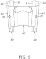
- FIG. 5 is a bottom view of part of the pair of rear frames 13 and the resin member 40.
- the pair of rear frames 13 is composed of a left rear frame 20 and a right rear frame 30.
- the left rear frame 20 is disposed on the left side with respect to the center of the vehicle body frame 2 in the vehicle width direction.
- the left rear frame 20 is disposed on the left side with respect to the head pipe 11.
- the left rear frame 20 includes a left seat frame 21, a left back stay 22, and a connecting portion 23.
- the left seat frame 21 extends rearward from the main frame 12.
- the left seat frame 21 extends further rearward than the left back stay 22.
- the left back stay 22 is disposed below the left seat frame 21.
- the left back stay 22 is disposed further on the outer side than the left seat frame 21 in the vehicle width direction.
- the left back stay 22 is disposed further on the left side than the left seat frame 21.
- the left back stay 22 extends rearward and upward from the main frame 12.
- the left back stay 22 includes a front end 22a and a rear end 22b.
- the front end 22a of the left back stay 22 is connected to the main frame 12.
- the rear end 22b of the left back stay 22 is connected to the left seat frame 21.
- the left back stay 22 tilts inward from the front end 22a toward the rear end 22b in the vehicle width direction.
- the connecting portion 23 connects the left seat frame 21 and the left back stay 22 therethrough.
- the connecting portion 23 extends in approximately the up-and-down direction.
- the connecting portion 23 extends downward from the vicinity of the middle of the left seat frame 21 toward the left back stay 22.
- the right rear frame 30 is disposed on the right side with respect to the center of the vehicle body frame 2 in the vehicle width direction.
- the right rear frame 30 is disposed on the right side with respect to the head pipe 11.
- the right rear frame 30 is disposed on the right side of the left rear frame 20.
- the right rear frame 30 includes a right seat frame 31, a right back stay 32, and a connecting portion 33.
- the right rear frame 30 is shaped bilaterally symmetric to the left rear frame 20; hence, the detailed explanation thereof will be hereinafter omitted.
- the first cross member 14 couples the left back stay 22 and the right back stay 32 therethrough.
- the first cross member 14 extends in the right-and-left direction.
- the first cross member 14 is disposed between the main frame 12 and each connecting portion 23, 33.
- the second cross member 15 is disposed on the rear ends of the pair of rear frames 13.
- the second cross member 15 couples the left seat frame 21 and the right seat frame 31 therethrough.
- the second cross member 15 is disposed further on the rear side than the first cross member 14.
- the second cross member 15 is disposed further on the rear side than the left back stay 22 and the right back stay 32.
- the steering device 3 is supported by the head pipe 11 so as to be turnable.
- the steering device 3 supports the front wheel 7 such that the front wheel 7 is made rotatable.
- the steering device 3 includes a steering shaft 17, a handle member 18, and a front fork 19.
- the steering shaft 17 is inserted into the head pipe 11.
- the handle member 18 is disposed above the head pipe 11.
- the handle member 18 extends in the right-and-left direction.
- the front fork 19 is connected to the steering shaft 17.
- the front fork 19 supports the front wheel 7 such that the front wheel 7 is made rotatable.
- the fuel tank 4 is disposed directly behind the head pipe 11.
- the fuel tank 4 is supported by the main frame 12.
- the seat 5 is disposed directly behind the fuel tank 4.
- the seat 5 is supported by the pair of rear frames 13.
- the seat 5 is disposed directly above the left seat frame 21 and the right seat frame 31.
- the drive source 6 is disposed directly below the fuel tank 4.
- the drive source 6 is supported by the main frame 12.
- the drive source 6 includes, for instance, an internal combustion engine.
- the front wheel 7 is supported by the front fork 19 so as to be rotatable.
- the rear wheel 8 is supported by the main frame 12 through a swing arm 9.
- the rear wheel 8 is supported by the swing arm 9 so as to be rotatable.
- the swing arm 9 is supported by the main frame 12 so as to be swingable.
- the straddled vehicle 1 includes the resin member 40 and a weight member 50.
- the resin member 40 is a plate-shaped member, the entirety of which is made of a resin material.
- the resin member 40 extends in both the back-and-forth direction and the right-and-left direction.
- the resin member 40 is bridged between the left rear frame 20 and the right rear frame 30.
- the resin member 40 is bridged between the left back stay 22 and the right back stay 32.
- the resin member 40 is disposed directly below the left back stay 22 and the right back stay 32.
- the resin member 40 is connected to a lower portion of the left back stay 22 and that of the right back stay 32.
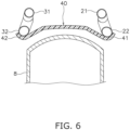
- FIG. 6 is a cross-sectional view of the rear wheel 8 and the resin member 40.
- the resin member 40 is disposed directly above the rear wheel 8.
- the resin member 40 overlaps with the rear wheel 8 in a vehicle plan view.
- the resin member 40 is disposed in approximately the middle of the pair of rear frames 13 in the back-and-forth direction.
- the resin member 40 is disposed between the first cross member 14 and the second cross member 15.
- the resin member 40 is disposed further on the rear side than the connecting portion 23 of the left rear frame 20 and the connecting portion 33 of the right rear frame 30.
- the resin member 40 is shaped to avoid interference with the rear wheel 8.
- the resin member 40 has a curved shape.
- the resin member 40 is shaped to curve in a direction remote from the surface of the rear wheel 8.
- the lower surface of the resin member 40 is shaped at least in part along the contour of the rear wheel 8.
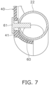
- the resin member 40 is fixed to the left rear frame 20 (and the right rear frame 30 as well) by an adhesive agent 60 and a fixation member 61 made of metal.
- the adhesive agent 60 is disposed not only between the resin member 40 and the left back stay 22 but also between the resin member 40 and the right back stay 32.
- the fixation member 61 made of metal is, for instance, a rivet made of metal.
- the resin member 40 includes a left attached portion 41 and a right attached portion 42.
- the left attached portion 41 is fixed to the left back stay 22 by the adhesive agent 60 and the metallic fixation member 61 at the lower portion of the left back stay 22.
- the left attached portion 41 is shaped along the contour of the left back stay 22.
- the right attached portion 42 is fixed to the right back stay 32 by the adhesive agent 60 and the metallic fixation member 61 at the lower portion of the right back stay 32.
- the right attached portion 42 is shaped along the contour of the right back stay 32.
- the weight member 50 is disposed on the resin member 40 so as to make the resin member 40 function as a dynamic damper.
- the weight member 50 is provided for making the resin member 40 exert vibrational characteristics that the vibrational phase of the resin member 40 is inverted to that of the pair of rear frames 13.
- the resin member 40 is configured to function as the dynamic damper by the weight member 50.
- the resonant frequency of the resin member 40 is adjusted in correspondence to the normal mode of the pair of rear frames 13.
- the positional arrangement of the weight member 50 is adjusted to deal with the vibrational characteristics of the pair of rear frames 13.
- the weight member 50 is made of a different material from the resin member 40.
- the weight member 50 is made of, for instance, metal.
- the weight member 50 is attached to the resin member 40 by, for instance, an adhesive agent.
- the weight member 50 is disposed on an upper portion of the resin member 40.
- the weight member 50 is disposed on a rear portion of the resin member 40.
- the weight member 50 may be attached to the resin member 40 by fixation means such as slip casting, resin molding, fastening with screws, or so forth.
- the weight member 50 includes a first weight portion 51 and a second weight portion 52.
- the first weight portion 51 is disposed on the left side with respect to the center of the vehicle body frame 2 in the vehicle width direction.
- the second weight portion 52 is disposed on the right side with respect to the center of the vehicle body frame 2 in the vehicle width direction.
- the second weight portion 52 is disposed in alignment with the first weight portion 51 in the vehicle width direction.
- the resin member 40 is configured to function as a dynamic damper by the weight member 50; hence, vibrations of the pair of rear frames 13, attributed to vibrations of the drive source 6 such as an internal combustion engine, can be reduced by the resin member 40. As a result, the vibrations of the pair of rear frames 13 can be inhibited from being transferred to the rider seated on the seat 5. Besides, the pair of rear frames 13 can be enhanced in stiffness by the resin member 40.
- the resin member 40 is more flexible in shape than a metallic member; hence, flexibility in layout of components is enhanced in the surroundings of the pair of rear frames 13.
- the straddled vehicle 1 is a so-called street motorcycle.
- the straddled vehicle 1 is not limited to the street motorcycle and may be an off-road motorcycle.
- the straddled vehicle 1 may be a scooter, an underbone, or a moped.
- the drive source 6 may include an electric motor.
- the resin member 40 and the weight member 50 may be changed in shape and/or layout.
- the resin member 40 may be bridged between the left seat frame 21 and the right seat frame 31.
- the adhesive agent 60 and the fixation members 61 may be omitted.
- the resin member 40 may be fixed to each of the left and right rear frames 20 and 30 by at least either the adhesive agent 60 or the fixation member 61.
- the resin member 40 may include a planar portion 43.
- the weight member 50 may be disposed on the planar portion 43 of the resin member 40.
- the weight member 50 may be disposed in such a position that vibrations of the planar portion 43, attributed to vibrations of the drive source 6, are maximized in amplitude.
- the planar portion 43 is disposed between the left rear frame 20 and the right rear frame 30.
- the planar portion 43 is provided in an upper portion of the resin member 40 so as to be disposed in the vicinity of the middle of the resin member 40 in the vehicle width direction.
- Part of the weight member 50 may be formed by part of the resin member 40.
- the weight member 50 may include a first weight portion 55 and a second weight portion 56.
- the first weight portion 55 is made of a different material from the resin member 40; by contrast, the second weight portion 56 is formed by increasing in part the thickness of the resin member 40.
- the resonant frequency of the resin member 40 may be adjusted by increasing in part the thickness of the resin member 40.
- the resonant frequency of the resin member 40 may be adjusted by increasing in part the thickness of the resin member 40 at the first and second weight portions 51 and 52.
- the weight member 50 may include a third weight portion disposed in a different position from the first and second weight portions 51 and 52.
- the number of weights composing the weight member 50 may be one, or alternatively, may be three or greater.
- the weight member 50 may include a plurality of weight portions aligned in the back-and-forth direction.
Landscapes
- Engineering & Computer Science (AREA)
- General Engineering & Computer Science (AREA)
- Mechanical Engineering (AREA)
- Automatic Cycles, And Cycles In General (AREA)
Abstract
Description
- The present invention relates to a straddled vehicle.
- There has been conventionally known a type of straddled vehicle including a pair of rear frames and a seat supported by the pair of rear frames (see
Japan Laid-open Patent Application Publication No. 2014-162425 - In the conventional type of straddled vehicle, the pair of rear frames is enhanced in stiffness by the seat receiver and the cross plate; however, it is concerned that vibrations of the pair of rear frames, attributed to vibrations of a drive source such as an engine, cannot be effectively inhibited only by enhancement in stiffness of the pair of rear frames. Besides, it is concerned that, when the members for enhancement in stiffness of the pair of rear frames are made of metal, flexibility in layout of components degrades in the surroundings of the pair of rear frames.
- It is an object of the present invention to reduce vibrations of the pair of rear frames, and simultaneously, enhance flexibility in layout of components in the surroundings of the pair of rear frames in a straddled vehicle.
- A straddled vehicle according to an aspect of the present invention includes a pair of rear frames, a seat, a resin member, and a weight member. The pair of rear frames includes a left rear frame and a right rear frame disposed apart from the left rear frame in a vehicle width direction. The seat is supported by the pair of rear frames. The resin member is bridged between the left rear frame and the right rear frame. The weight member is disposed on the resin member so as to make the resin member function as a dynamic damper.
- In the straddled vehicle according to the present aspect, the resin member is configured to function as the dynamic damper by the weight member; hence, vibrations of the pair of rear frames, attributed to vibrations of a drive source such as an engine, can be reduced by the resin member. As a result, vibrations of the pair of rear frames can be inhibited from being transferred to a rider seated on the seat. Besides, the resin member is more flexible in shape than a member made of metal; hence, flexibility in layout of components is enhanced in the surroundings of the pair of rear frames.
- The weight member may be made of a different material from the resin member. In this case, adjustment in weight of the weight member is made easy.
- The weight member may be made of metal. In this case, increase in size of the weight member can be inhibited; simultaneously, the weight member is reliably enabled to have sufficient weight.
- The weight member may include a first weight portion and a second weight portion. The first weight portion may be made of a different material from the resin member. The second weight portion may be formed by increasing in part a thickness of the resin member. In this case, the weight member is reliably enabled to have sufficient weight even by part of the resin member; hence, the resin member can be adjusted in resonant frequency by part of the resin member and the weight member.
- The resin member may include a planar portion disposed between the left rear frame and the right rear frame. The weight member may be disposed on the planar portion of the resin member. In this case, vibrations of the pair of rear frames can be effectively reduced.
- The straddled vehicle may further include a drive source generating a drive force. The weight member may be disposed in a position that vibrations of the planar portion attributed to vibrations of the drive source are maximized in amplitude. In this case, vibrations attributed to those of the drive source can be effectively reduced by the resin member.
- The weight member may include a first weight portion and a second weight portion disposed in alignment with the first weight portion in the vehicle width direction. In this case, vibrations of the pair of rear frames can be effectively reduced.
- The resin member may be fixed to the left rear frame and the right rear frame by an adhesive agent. In this case, the pair of rear frames can be enhanced in stiffness.
- The resin member may be fixed to the left rear frame and the right rear frame by a fixation member made of metal. In this case, the pair of rear frames can be enhanced in stiffness; simultaneously, the resin member can be prevented from being unfixed and dropping from the pair of rear frames.
- The resin member may be fixed to the left rear frame and the right rear frame by an adhesive agent and a fixation member made of metal. In this case, the pair of rear frames can be enhanced in stiffness; simultaneously, the resin member can be prevented from being unfixed and dropping from the pair of rear frames.
- The straddled vehicle may further include a rear wheel disposed directly below the pair of rear frames. The resin member may be disposed directly above the rear wheel. In this case, the resin member can be disposed in such a region of the pair of rear frames that enables the resin member to reduce vibrations to be transferred to the seat highly effectively; hence, vibrations of the pair of rear frames can be effectively inhibited from being transferred to the rider seated on the seat.
- The resin member may be shaped to avoid interference with the rear wheel. In this case, the resin member can be inhibited from interfering with the rear wheel. Besides, the resin member is more flexible in shape than a member made of metal. Therefore, the resin member is reliably enabled to have sufficient stiffness; simultaneously, flexibility in layout of components can be enhanced in the surroundings of the pair of rear frames.
- The resin member may have a curved shape. In this case, the resin member is reliably enabled to have sufficient stiffness; simultaneously, flexibility in layout of components can be further enhanced in the surroundings of the pair of rear frames.
- The left rear frame may include a left seat frame and a left back stay disposed below the left seat frame. The right rear frame may include a right seat frame and a right back stay disposed below the right seat frame. The resin member may be bridged between the left back stay and the right back stay. In this case, flexibility in layout of components can be enhanced in the surroundings of the pair of rear frames.
- The left back stay may be disposed further on an outer side than the left seat frame in the vehicle width direction. The right back stay may be disposed further on an outer side than the right seat frame in the vehicle width direction. In this case, flexibility in layout of components can be further enhanced in the surroundings of the pair of rear frames.
- Overall, according to the present invention, in a straddled vehicle, vibrations of the pair of rear frames can be reduced, and simultaneously, flexibility in layout of components can be enhanced in the surroundings of the pair of rear frames.
-
-
FIG. 1 is a left side view of a straddled vehicle. -
FIG. 2 is a perspective view of a pair of rear frames and the surroundings thereof. -
FIG. 3 is a perspective view of the pair of rear frames and a resin member. -
FIG. 4 is a plan view of part of the pair of rear frames and the resin member. -
FIG. 5 is a bottom view of part of the pair of rear frames and the resin member. -
FIG. 6 is a cross-sectional view of a rear wheel and the resin member. -
FIG. 7 is a cross-sectional view of a fixation member and the surroundings thereof. -
FIG. 8 is a cross-sectional view of the resin member and a weight member. -
FIG. 9 is a cross-sectional view of a resin member and a weight member according to a first modification. -
FIG. 10 is a cross-sectional view of a resin member and a weight member according to a second modification. - A preferred embodiment of a straddled vehicle according to an aspect of the present invention will be hereinafter explained with reference to drawings. It should be noted that in the following explanation, terms indicating such directions as "back and forth", "up and down" and "right and left" are explained based on directions seen from a rider in operation of the straddled vehicle. Therefore, a right-and-left direction is synonymous with a vehicle width direction. Besides, the term "outer side in a vehicle width direction" means a side far from the center of the straddled vehicle in the vehicle width direction. By contrast, the term "inner side in the vehicle width direction" means a side near to the center of the straddled vehicle in the vehicle width direction.
-
FIG. 1 is a left side view of a straddled vehicle 1. The straddled vehicle 1 includes avehicle body frame 2, a steering device 3, a fuel tank 4, a seat 5, adrive source 6, afront wheel 7, and arear wheel 8. - The
vehicle body frame 2 includes a head pipe 11, amain frame 12, a pair ofrear frames 13, afirst cross member 14, and asecond cross member 15. - In a vehicle side view, the head pipe 11 extends forward and downward from the upper end thereof to the lower end thereof. The head pipe 11 is disposed in the middle of the vehicle in the vehicle width direction.
- The
main frame 12 is connected to the head pipe 11 and extends therefrom rearward, while branching therefrom right and left into components. It should be noted that the term "connection" is not limited to direct connection and encompasses indirect connection. Besides, the term "connection" is not limited to a condition that separate members are fixed to each other and encompasses a condition that a plurality of portions in an integrated member continue to each other. - The pair of
rear frames 13 is connected to themain frame 12. The pair ofrear frames 13 extends rearward from themain frame 12. -
FIG. 2 is a perspective view of the pair ofrear frames 13 and the surroundings thereof.FIG. 3 is a perspective view of the pair ofrear frames 13 and a resin member 40 (to be described).FIG. 4 is a plan view of part of the pair ofrear frames 13 and theresin member 40.FIG. 5 is a bottom view of part of the pair ofrear frames 13 and theresin member 40. - As shown in
FIGS. 2 to 5 , the pair ofrear frames 13 is composed of a leftrear frame 20 and a rightrear frame 30. The leftrear frame 20 is disposed on the left side with respect to the center of thevehicle body frame 2 in the vehicle width direction. The leftrear frame 20 is disposed on the left side with respect to the head pipe 11. - The left
rear frame 20 includes aleft seat frame 21, aleft back stay 22, and a connectingportion 23. Theleft seat frame 21 extends rearward from themain frame 12. Theleft seat frame 21 extends further rearward than theleft back stay 22. - The
left back stay 22 is disposed below theleft seat frame 21. Theleft back stay 22 is disposed further on the outer side than theleft seat frame 21 in the vehicle width direction. Theleft back stay 22 is disposed further on the left side than theleft seat frame 21. Theleft back stay 22 extends rearward and upward from themain frame 12. - The
left back stay 22 includes afront end 22a and arear end 22b. Thefront end 22a of theleft back stay 22 is connected to themain frame 12. Therear end 22b of theleft back stay 22 is connected to theleft seat frame 21. The left back stay 22 tilts inward from thefront end 22a toward therear end 22b in the vehicle width direction. - The connecting
portion 23 connects theleft seat frame 21 and the left back stay 22 therethrough. The connectingportion 23 extends in approximately the up-and-down direction. The connectingportion 23 extends downward from the vicinity of the middle of theleft seat frame 21 toward theleft back stay 22. - The right
rear frame 30 is disposed on the right side with respect to the center of thevehicle body frame 2 in the vehicle width direction. The rightrear frame 30 is disposed on the right side with respect to the head pipe 11. The rightrear frame 30 is disposed on the right side of the leftrear frame 20. The rightrear frame 30 includes aright seat frame 31, a right back stay 32, and a connectingportion 33. The rightrear frame 30 is shaped bilaterally symmetric to the leftrear frame 20; hence, the detailed explanation thereof will be hereinafter omitted. - As shown in
FIGS. 2 and3 , thefirst cross member 14 couples theleft back stay 22 and the right back stay 32 therethrough. Thefirst cross member 14 extends in the right-and-left direction. Thefirst cross member 14 is disposed between themain frame 12 and each connectingportion - The
second cross member 15 is disposed on the rear ends of the pair of rear frames 13. Thesecond cross member 15 couples theleft seat frame 21 and theright seat frame 31 therethrough. Thesecond cross member 15 is disposed further on the rear side than thefirst cross member 14. Thesecond cross member 15 is disposed further on the rear side than theleft back stay 22 and the right back stay 32. - As shown in
FIG. 1 , the steering device 3 is supported by the head pipe 11 so as to be turnable. The steering device 3 supports thefront wheel 7 such that thefront wheel 7 is made rotatable. The steering device 3 includes a steeringshaft 17, ahandle member 18, and afront fork 19. The steeringshaft 17 is inserted into the head pipe 11. Thehandle member 18 is disposed above the head pipe 11. Thehandle member 18 extends in the right-and-left direction. Thefront fork 19 is connected to the steeringshaft 17. Thefront fork 19 supports thefront wheel 7 such that thefront wheel 7 is made rotatable. - The fuel tank 4 is disposed directly behind the head pipe 11. The fuel tank 4 is supported by the
main frame 12. - The seat 5 is disposed directly behind the fuel tank 4. The seat 5 is supported by the pair of rear frames 13. The seat 5 is disposed directly above the
left seat frame 21 and theright seat frame 31. - The
drive source 6 is disposed directly below the fuel tank 4. Thedrive source 6 is supported by themain frame 12. Thedrive source 6 includes, for instance, an internal combustion engine. - The
front wheel 7 is supported by thefront fork 19 so as to be rotatable. Therear wheel 8 is supported by themain frame 12 through aswing arm 9. Therear wheel 8 is supported by theswing arm 9 so as to be rotatable. Theswing arm 9 is supported by themain frame 12 so as to be swingable. - As shown in
FIGS. 2 to 5 , the straddled vehicle 1 includes theresin member 40 and aweight member 50. Theresin member 40 is a plate-shaped member, the entirety of which is made of a resin material. Theresin member 40 extends in both the back-and-forth direction and the right-and-left direction. Theresin member 40 is bridged between the leftrear frame 20 and the rightrear frame 30. In the present preferred embodiment, theresin member 40 is bridged between theleft back stay 22 and the right back stay 32. Theresin member 40 is disposed directly below theleft back stay 22 and the right back stay 32. Theresin member 40 is connected to a lower portion of theleft back stay 22 and that of the right back stay 32. -
FIG. 6 is a cross-sectional view of therear wheel 8 and theresin member 40. As shown inFIG. 6 , theresin member 40 is disposed directly above therear wheel 8. Theresin member 40 overlaps with therear wheel 8 in a vehicle plan view. Theresin member 40 is disposed in approximately the middle of the pair ofrear frames 13 in the back-and-forth direction. Theresin member 40 is disposed between thefirst cross member 14 and thesecond cross member 15. Theresin member 40 is disposed further on the rear side than the connectingportion 23 of the leftrear frame 20 and the connectingportion 33 of the rightrear frame 30. - The
resin member 40 is shaped to avoid interference with therear wheel 8. Theresin member 40 has a curved shape. Theresin member 40 is shaped to curve in a direction remote from the surface of therear wheel 8. The lower surface of theresin member 40 is shaped at least in part along the contour of therear wheel 8. - As shown in
FIG. 7 , theresin member 40 is fixed to the left rear frame 20 (and the rightrear frame 30 as well) by anadhesive agent 60 and afixation member 61 made of metal. Theadhesive agent 60 is disposed not only between theresin member 40 and the left back stay 22 but also between theresin member 40 and the right back stay 32. Thefixation member 61 made of metal is, for instance, a rivet made of metal. - The
resin member 40 includes a left attachedportion 41 and a right attachedportion 42. The left attachedportion 41 is fixed to the left back stay 22 by theadhesive agent 60 and themetallic fixation member 61 at the lower portion of theleft back stay 22. The left attachedportion 41 is shaped along the contour of theleft back stay 22. The right attachedportion 42 is fixed to the right back stay 32 by theadhesive agent 60 and themetallic fixation member 61 at the lower portion of the right back stay 32. The right attachedportion 42 is shaped along the contour of the right back stay 32. - The
weight member 50 is disposed on theresin member 40 so as to make theresin member 40 function as a dynamic damper. In other words, theweight member 50 is provided for making theresin member 40 exert vibrational characteristics that the vibrational phase of theresin member 40 is inverted to that of the pair of rear frames 13. Accordingly, theresin member 40 is configured to function as the dynamic damper by theweight member 50. In this case, for instance, by adjusting the weight of theweight member 50, the resonant frequency of theresin member 40 is adjusted in correspondence to the normal mode of the pair of rear frames 13. The positional arrangement of theweight member 50 is adjusted to deal with the vibrational characteristics of the pair of rear frames 13. - As shown in
FIG. 8 , theweight member 50 is made of a different material from theresin member 40. Theweight member 50 is made of, for instance, metal. Theweight member 50 is attached to theresin member 40 by, for instance, an adhesive agent. Theweight member 50 is disposed on an upper portion of theresin member 40. Theweight member 50 is disposed on a rear portion of theresin member 40. Theweight member 50 may be attached to theresin member 40 by fixation means such as slip casting, resin molding, fastening with screws, or so forth. - The
weight member 50 includes afirst weight portion 51 and asecond weight portion 52. Thefirst weight portion 51 is disposed on the left side with respect to the center of thevehicle body frame 2 in the vehicle width direction. Thesecond weight portion 52 is disposed on the right side with respect to the center of thevehicle body frame 2 in the vehicle width direction. Thesecond weight portion 52 is disposed in alignment with thefirst weight portion 51 in the vehicle width direction. - In the straddled vehicle 1 according to the present aspect, the
resin member 40 is configured to function as a dynamic damper by theweight member 50; hence, vibrations of the pair ofrear frames 13, attributed to vibrations of thedrive source 6 such as an internal combustion engine, can be reduced by theresin member 40. As a result, the vibrations of the pair ofrear frames 13 can be inhibited from being transferred to the rider seated on the seat 5. Besides, the pair ofrear frames 13 can be enhanced in stiffness by theresin member 40. Theresin member 40 is more flexible in shape than a metallic member; hence, flexibility in layout of components is enhanced in the surroundings of the pair of rear frames 13. - One preferred embodiment of the present invention has been explained above. However, the present invention is not limited to the preferred embodiment described above, and a variety of changes can be made without departing from the gist of the present invention.
- The straddled vehicle 1 according to the present preferred embodiment is a so-called street motorcycle. However, the straddled vehicle 1 is not limited to the street motorcycle and may be an off-road motorcycle. Alternatively, the straddled vehicle 1 may be a scooter, an underbone, or a moped. The
drive source 6 may include an electric motor. - The
resin member 40 and theweight member 50 may be changed in shape and/or layout. Theresin member 40 may be bridged between theleft seat frame 21 and theright seat frame 31. Theadhesive agent 60 and thefixation members 61 may be omitted. Theresin member 40 may be fixed to each of the left and right rear frames 20 and 30 by at least either theadhesive agent 60 or thefixation member 61. - As shown in
FIG. 9 , theresin member 40 may include aplanar portion 43. Theweight member 50 may be disposed on theplanar portion 43 of theresin member 40. Theweight member 50 may be disposed in such a position that vibrations of theplanar portion 43, attributed to vibrations of thedrive source 6, are maximized in amplitude. Theplanar portion 43 is disposed between the leftrear frame 20 and the rightrear frame 30. Theplanar portion 43 is provided in an upper portion of theresin member 40 so as to be disposed in the vicinity of the middle of theresin member 40 in the vehicle width direction. - Part of the
weight member 50 may be formed by part of theresin member 40. For example, as shown inFIG. 10 , theweight member 50 may include afirst weight portion 55 and asecond weight portion 56. Thefirst weight portion 55 is made of a different material from theresin member 40; by contrast, thesecond weight portion 56 is formed by increasing in part the thickness of theresin member 40. In other words, the resonant frequency of theresin member 40 may be adjusted by increasing in part the thickness of theresin member 40. Likewise, in the preferred embodiment described above, the resonant frequency of theresin member 40 may be adjusted by increasing in part the thickness of theresin member 40 at the first andsecond weight portions - The
weight member 50 may include a third weight portion disposed in a different position from the first andsecond weight portions weight member 50 may be one, or alternatively, may be three or greater. Theweight member 50 may include a plurality of weight portions aligned in the back-and-forth direction. -
- 1
- Straddled vehicle
- 6
- Drive source
- 8
- Rear wheel
- 13
- Pair of rear frames
- 20
- Left rear frame
- 21
- Left seat frame
- 22
- Left back stay
- 30
- Right rear frame
- 31
- Right seat frame
- 32
- Right back stay
- 40
- Resin member
- 43
- Flat planar portion
- 50
- Weight member
- 51
- First weight portion
- 52
- Second weight portion
- 60
- Adhesive agent
- 61
- Fixation member
Claims (15)
- A straddled vehicle (1) comprising:a pair of rear frames (13) including a left rear frame (20) and a right rear frame (30), the right rear frame (30) being disposed apart from the left rear frame (20) in a vehicle width direction;a seat (5) supported by the pair of rear frames (13);a resin member (40) bridged between the left rear frame (20) and the right rear frame (30); anda weight member (50) disposed on the resin member (40) so as to make the resin member (40) function as a dynamic damper.
- The straddled vehicle according to claim 1, wherein the weight member (50) is made of a different material from the resin member (40).
- The straddled vehicle according to claim 1 or 2, wherein the weight member (50) is made of metal.
- The straddled vehicle according to claim 1, wherein the weight member (50) includes a first weight portion (51) and a second weight portion (52), the first weight portion (51) made of a different material from the resin member (40), the second weight portion (52) formed by increasing in part a thickness of the resin member (40).
- The straddled vehicle according to any one of claims 1 to 4, whereinthe resin member (40) includes a planar portion (43) disposed between the left rear frame (20) and the right rear frame (30), andthe weight member (50) is disposed on the planar portion of the resin member (40).
- The straddled vehicle according to claim 5, further comprising:a drive source (6) generating a drive force, whereinthe weight member (50) is disposed in a position that vibrations of the planar portion (43) attributed to vibrations of the drive source (6) are maximized in amplitude.
- The straddled vehicle according to claim 1, wherein the weight member (50) includes a first weight portion (51) and a second weight portion (52), the second weight portion (52) being disposed in alignment with the first weight portion (51) in the vehicle width direction.
- The straddled vehicle according to any one of claims 1 to 7, wherein the resin member (40) is fixed to the left rear frame (20) and the right rear frame (30) by an adhesive agent.
- The straddled vehicle according to any one of claims 1 to 7, wherein the resin member (40) is fixed to the left rear frame (20) and the right rear frame (30) by a fixation member (61) made of metal.
- The straddled vehicle according to any one of claims 1 to 7, wherein the resin member (40) is fixed to the left rear frame (20) and the right rear frame (30) by an adhesive agent (60) and a fixation member (61) made of metal.
- The straddled vehicle according to any one of claims 1 to 10, further comprising:a rear wheel (8) disposed directly below the pair of rear frames (13), whereinthe resin member (40) is disposed directly above the rear wheel (8).
- The straddled vehicle according to claim 11, wherein the resin member (40) is shaped to avoid interference with the rear wheel (8).
- The straddled vehicle according to any one of claims 1 to 12, wherein the resin member (40) has a curved shape.
- The straddled vehicle according to any one of claims 1 to 13, whereinthe left rear frame (20) includes a left seat frame (21) and a left back stay (22), the left back stay (22) being disposed below the left seat frame (21),the right rear frame (30) includes a right seat frame (31) and a right back stay (32), the right back stay (32) being disposed below the right seat frame (31), andthe resin member (40) is bridged between the left back stay (22) and the right back stay (32).
- The straddled vehicle according to claim 14, whereinthe left back stay (22) is disposed further on an outer side than the left seat frame (21) in the vehicle width direction, andthe right back stay (32) is disposed further on an outer side than the right seat frame (31) in the vehicle width direction.
Applications Claiming Priority (1)
| Application Number | Priority Date | Filing Date | Title |
|---|---|---|---|
| JP2022160525A JP2024053974A (en) | 2022-10-04 | 2022-10-04 | Saddle type vehicle |
Publications (2)
| Publication Number | Publication Date |
|---|---|
| EP4349697A1 true EP4349697A1 (en) | 2024-04-10 |
| EP4349697B1 EP4349697B1 (en) | 2025-10-01 |
Family
ID=87418668
Family Applications (1)
| Application Number | Title | Priority Date | Filing Date |
|---|---|---|---|
| EP23186016.4A Active EP4349697B1 (en) | 2022-10-04 | 2023-07-18 | Straddled vehicle |
Country Status (2)
| Country | Link |
|---|---|
| EP (1) | EP4349697B1 (en) |
| JP (1) | JP2024053974A (en) |
Citations (7)
| Publication number | Priority date | Publication date | Assignee | Title |
|---|---|---|---|---|
| JPH03220079A (en) * | 1989-11-30 | 1991-09-27 | Yamaha Motor Co Ltd | Frame structure of motorcycle |
| JPH0572689U (en) * | 1992-03-12 | 1993-10-05 | スズキ株式会社 | Frame anti-vibration structure for motorcycles |
| JP4367872B2 (en) * | 1999-09-24 | 2009-11-18 | 本田技研工業株式会社 | Body frame anti-vibration structure for saddle riding type vehicles |
| JP2014162425A (en) | 2013-02-27 | 2014-09-08 | Honda Motor Co Ltd | Vehicle body frame for saddle-riding type vehicle |
| JP5702071B2 (en) * | 2010-03-10 | 2015-04-15 | 川崎重工業株式会社 | Motorcycle |
| US10232900B2 (en) * | 2015-03-31 | 2019-03-19 | Honda Motor Co., Ltd. | Saddle-ride-type vehicle |
| DE112017007375T5 (en) * | 2017-03-30 | 2019-12-05 | Honda Motor Co., Ltd. | VEHICLE CARRIER CONSTRUCTION OF A VEHICLE OF SADDLE TYPE |
-
2022
- 2022-10-04 JP JP2022160525A patent/JP2024053974A/en active Pending
-
2023
- 2023-07-18 EP EP23186016.4A patent/EP4349697B1/en active Active
Patent Citations (7)
| Publication number | Priority date | Publication date | Assignee | Title |
|---|---|---|---|---|
| JPH03220079A (en) * | 1989-11-30 | 1991-09-27 | Yamaha Motor Co Ltd | Frame structure of motorcycle |
| JPH0572689U (en) * | 1992-03-12 | 1993-10-05 | スズキ株式会社 | Frame anti-vibration structure for motorcycles |
| JP4367872B2 (en) * | 1999-09-24 | 2009-11-18 | 本田技研工業株式会社 | Body frame anti-vibration structure for saddle riding type vehicles |
| JP5702071B2 (en) * | 2010-03-10 | 2015-04-15 | 川崎重工業株式会社 | Motorcycle |
| JP2014162425A (en) | 2013-02-27 | 2014-09-08 | Honda Motor Co Ltd | Vehicle body frame for saddle-riding type vehicle |
| US10232900B2 (en) * | 2015-03-31 | 2019-03-19 | Honda Motor Co., Ltd. | Saddle-ride-type vehicle |
| DE112017007375T5 (en) * | 2017-03-30 | 2019-12-05 | Honda Motor Co., Ltd. | VEHICLE CARRIER CONSTRUCTION OF A VEHICLE OF SADDLE TYPE |
Also Published As
| Publication number | Publication date |
|---|---|
| JP2024053974A (en) | 2024-04-16 |
| EP4349697B1 (en) | 2025-10-01 |
Similar Documents
| Publication | Publication Date | Title |
|---|---|---|
| JP2008222079A (en) | Motorcycle | |
| US10625802B2 (en) | Rear fender supporting structure of saddle-type vehicle | |
| EP1452432B1 (en) | Frame structure of a motorcycle | |
| EP4349697B1 (en) | Straddled vehicle | |
| JP7671028B2 (en) | Mounting bracket | |
| JP2014177242A (en) | Saddle-riding type vehicle | |
| JP2022184501A (en) | straddle-type vehicle | |
| JP2019119329A (en) | Resin component for vehicle | |
| JP4377102B2 (en) | Scooter type motorcycle | |
| EP3366562A1 (en) | Swing arm structure for saddle riding vehicle | |
| JP2016179738A (en) | Saddle type fuel cell vehicle | |
| US9796445B2 (en) | Steered wheel suspension device | |
| JP2022050799A (en) | Saddle-riding type vehicle | |
| JP2005119570A (en) | Scooter-type vehicle body structure | |
| EP3015353B1 (en) | Straddle-type vehicle | |
| EP2161189B1 (en) | Motorcycle | |
| US7497295B2 (en) | Motorcycle having a support for controlling vibrations transmitted to a seat thereof | |
| US20050211492A1 (en) | Power train supporting apparatus and method for automotive vehicle | |
| JP2006015837A (en) | Motorcycle | |
| JP7351878B2 (en) | saddle type vehicle | |
| JP3496865B2 (en) | Stepping device for motorcycle | |
| EP2711277A1 (en) | Frame structure for saddle-riding type automotive vehicle | |
| JP2000062671A (en) | Rear fender mounting structure for motorcycles | |
| JP3015961B2 (en) | Rear wheel shock absorber for vehicles | |
| EP2025588B1 (en) | Frame of motorcycle and motorcycle |
Legal Events
| Date | Code | Title | Description |
|---|---|---|---|
| PUAI | Public reference made under article 153(3) epc to a published international application that has entered the european phase |
Free format text: ORIGINAL CODE: 0009012 |
|
| STAA | Information on the status of an ep patent application or granted ep patent |
Free format text: STATUS: REQUEST FOR EXAMINATION WAS MADE |
|
| 17P | Request for examination filed |
Effective date: 20230718 |
|
| AK | Designated contracting states |
Kind code of ref document: A1 Designated state(s): AL AT BE BG CH CY CZ DE DK EE ES FI FR GB GR HR HU IE IS IT LI LT LU LV MC ME MK MT NL NO PL PT RO RS SE SI SK SM TR |
|
| P01 | Opt-out of the competence of the unified patent court (upc) registered |
Free format text: CASE NUMBER: APP_41346/2024 Effective date: 20240712 |
|
| STAA | Information on the status of an ep patent application or granted ep patent |
Free format text: STATUS: EXAMINATION IS IN PROGRESS |
|
| 17Q | First examination report despatched |
Effective date: 20241009 |
|
| GRAP | Despatch of communication of intention to grant a patent |
Free format text: ORIGINAL CODE: EPIDOSNIGR1 |
|
| STAA | Information on the status of an ep patent application or granted ep patent |
Free format text: STATUS: GRANT OF PATENT IS INTENDED |
|
| INTG | Intention to grant announced |
Effective date: 20250424 |
|
| GRAS | Grant fee paid |
Free format text: ORIGINAL CODE: EPIDOSNIGR3 |
|
| GRAA | (expected) grant |
Free format text: ORIGINAL CODE: 0009210 |
|
| STAA | Information on the status of an ep patent application or granted ep patent |
Free format text: STATUS: THE PATENT HAS BEEN GRANTED |
|
| AK | Designated contracting states |
Kind code of ref document: B1 Designated state(s): AL AT BE BG CH CY CZ DE DK EE ES FI FR GB GR HR HU IE IS IT LI LT LU LV MC ME MK MT NL NO PL PT RO RS SE SI SK SM TR |
|
| REG | Reference to a national code |
Ref country code: GB Ref legal event code: FG4D Ref country code: CH Ref legal event code: F10 Free format text: ST27 STATUS EVENT CODE: U-0-0-F10-F00 (AS PROVIDED BY THE NATIONAL OFFICE) Effective date: 20251001 |
|
| REG | Reference to a national code |
Ref country code: IE Ref legal event code: FG4D |
|
| REG | Reference to a national code |
Ref country code: DE Ref legal event code: R096 Ref document number: 602023007075 Country of ref document: DE |
|
| REG | Reference to a national code |
Ref country code: NL Ref legal event code: MP Effective date: 20251001 |
|
| REG | Reference to a national code |
Ref country code: AT Ref legal event code: MK05 Ref document number: 1842274 Country of ref document: AT Kind code of ref document: T Effective date: 20251001 |
|
| PG25 | Lapsed in a contracting state [announced via postgrant information from national office to epo] |
Ref country code: NL Free format text: LAPSE BECAUSE OF FAILURE TO SUBMIT A TRANSLATION OF THE DESCRIPTION OR TO PAY THE FEE WITHIN THE PRESCRIBED TIME-LIMIT Effective date: 20251001 |
|
| PG25 | Lapsed in a contracting state [announced via postgrant information from national office to epo] |
Ref country code: ES Free format text: LAPSE BECAUSE OF FAILURE TO SUBMIT A TRANSLATION OF THE DESCRIPTION OR TO PAY THE FEE WITHIN THE PRESCRIBED TIME-LIMIT Effective date: 20251001 |
|
| REG | Reference to a national code |
Ref country code: LT Ref legal event code: MG9D |
|
| PG25 | Lapsed in a contracting state [announced via postgrant information from national office to epo] |
Ref country code: NO Free format text: LAPSE BECAUSE OF FAILURE TO SUBMIT A TRANSLATION OF THE DESCRIPTION OR TO PAY THE FEE WITHIN THE PRESCRIBED TIME-LIMIT Effective date: 20260101 |
|
| PG25 | Lapsed in a contracting state [announced via postgrant information from national office to epo] |
Ref country code: FI Free format text: LAPSE BECAUSE OF FAILURE TO SUBMIT A TRANSLATION OF THE DESCRIPTION OR TO PAY THE FEE WITHIN THE PRESCRIBED TIME-LIMIT Effective date: 20251001 Ref country code: HR Free format text: LAPSE BECAUSE OF FAILURE TO SUBMIT A TRANSLATION OF THE DESCRIPTION OR TO PAY THE FEE WITHIN THE PRESCRIBED TIME-LIMIT Effective date: 20251001 Ref country code: AT Free format text: LAPSE BECAUSE OF FAILURE TO SUBMIT A TRANSLATION OF THE DESCRIPTION OR TO PAY THE FEE WITHIN THE PRESCRIBED TIME-LIMIT Effective date: 20251001 |
|
| PG25 | Lapsed in a contracting state [announced via postgrant information from national office to epo] |
Ref country code: RS Free format text: LAPSE BECAUSE OF FAILURE TO SUBMIT A TRANSLATION OF THE DESCRIPTION OR TO PAY THE FEE WITHIN THE PRESCRIBED TIME-LIMIT Effective date: 20260101 |
|
| PG25 | Lapsed in a contracting state [announced via postgrant information from national office to epo] |
Ref country code: IS Free format text: LAPSE BECAUSE OF FAILURE TO SUBMIT A TRANSLATION OF THE DESCRIPTION OR TO PAY THE FEE WITHIN THE PRESCRIBED TIME-LIMIT Effective date: 20260201 |
|
| PG25 | Lapsed in a contracting state [announced via postgrant information from national office to epo] |
Ref country code: PT Free format text: LAPSE BECAUSE OF FAILURE TO SUBMIT A TRANSLATION OF THE DESCRIPTION OR TO PAY THE FEE WITHIN THE PRESCRIBED TIME-LIMIT Effective date: 20260202 Ref country code: CZ Free format text: LAPSE BECAUSE OF FAILURE TO SUBMIT A TRANSLATION OF THE DESCRIPTION OR TO PAY THE FEE WITHIN THE PRESCRIBED TIME-LIMIT Effective date: 20251001 |
|
| PG25 | Lapsed in a contracting state [announced via postgrant information from national office to epo] |
Ref country code: PL Free format text: LAPSE BECAUSE OF FAILURE TO SUBMIT A TRANSLATION OF THE DESCRIPTION OR TO PAY THE FEE WITHIN THE PRESCRIBED TIME-LIMIT Effective date: 20251001 |
|
| PG25 | Lapsed in a contracting state [announced via postgrant information from national office to epo] |
Ref country code: LV Free format text: LAPSE BECAUSE OF FAILURE TO SUBMIT A TRANSLATION OF THE DESCRIPTION OR TO PAY THE FEE WITHIN THE PRESCRIBED TIME-LIMIT Effective date: 20251001 |
|
| PG25 | Lapsed in a contracting state [announced via postgrant information from national office to epo] |
Ref country code: BG Free format text: LAPSE BECAUSE OF FAILURE TO SUBMIT A TRANSLATION OF THE DESCRIPTION OR TO PAY THE FEE WITHIN THE PRESCRIBED TIME-LIMIT Effective date: 20251001 |
|
| PG25 | Lapsed in a contracting state [announced via postgrant information from national office to epo] |
Ref country code: LT Free format text: LAPSE BECAUSE OF FAILURE TO SUBMIT A TRANSLATION OF THE DESCRIPTION OR TO PAY THE FEE WITHIN THE PRESCRIBED TIME-LIMIT Effective date: 20251001 |
|
| REG | Reference to a national code |
Ref country code: DE Ref legal event code: R097 Ref document number: 602023007075 Country of ref document: DE |
|
| PG25 | Lapsed in a contracting state [announced via postgrant information from national office to epo] |
Ref country code: SM Free format text: LAPSE BECAUSE OF FAILURE TO SUBMIT A TRANSLATION OF THE DESCRIPTION OR TO PAY THE FEE WITHIN THE PRESCRIBED TIME-LIMIT Effective date: 20251001 |
|
| PG25 | Lapsed in a contracting state [announced via postgrant information from national office to epo] |
Ref country code: DK Free format text: LAPSE BECAUSE OF FAILURE TO SUBMIT A TRANSLATION OF THE DESCRIPTION OR TO PAY THE FEE WITHIN THE PRESCRIBED TIME-LIMIT Effective date: 20251001 |
|
| PG25 | Lapsed in a contracting state [announced via postgrant information from national office to epo] |
Ref country code: EE Free format text: LAPSE BECAUSE OF FAILURE TO SUBMIT A TRANSLATION OF THE DESCRIPTION OR TO PAY THE FEE WITHIN THE PRESCRIBED TIME-LIMIT Effective date: 20251001 |
|
| PG25 | Lapsed in a contracting state [announced via postgrant information from national office to epo] |
Ref country code: SK Free format text: LAPSE BECAUSE OF FAILURE TO SUBMIT A TRANSLATION OF THE DESCRIPTION OR TO PAY THE FEE WITHIN THE PRESCRIBED TIME-LIMIT Effective date: 20251001 |
|
| PG25 | Lapsed in a contracting state [announced via postgrant information from national office to epo] |
Ref country code: SE Free format text: LAPSE BECAUSE OF FAILURE TO SUBMIT A TRANSLATION OF THE DESCRIPTION OR TO PAY THE FEE WITHIN THE PRESCRIBED TIME-LIMIT Effective date: 20251001 |
|
| PLBE | No opposition filed within time limit |
Free format text: ORIGINAL CODE: 0009261 |
|
| STAA | Information on the status of an ep patent application or granted ep patent |
Free format text: STATUS: NO OPPOSITION FILED WITHIN TIME LIMIT |
|
| REG | Reference to a national code |
Ref country code: CH Ref legal event code: L10 Free format text: ST27 STATUS EVENT CODE: U-0-0-L10-L00 (AS PROVIDED BY THE NATIONAL OFFICE) Effective date: 20260812 |