EP4349645A1 - Seat assembly for a vehicle, vehicle and methods - Google Patents
Seat assembly for a vehicle, vehicle and methods Download PDFInfo
- Publication number
- EP4349645A1 EP4349645A1 EP22199555.8A EP22199555A EP4349645A1 EP 4349645 A1 EP4349645 A1 EP 4349645A1 EP 22199555 A EP22199555 A EP 22199555A EP 4349645 A1 EP4349645 A1 EP 4349645A1
- Authority
- EP
- European Patent Office
- Prior art keywords
- seat assembly
- sitting
- primary
- back rest
- state
- Prior art date
- Legal status (The legal status is an assumption and is not a legal conclusion. Google has not performed a legal analysis and makes no representation as to the accuracy of the status listed.)
- Pending
Links
- 238000000034 method Methods 0.000 title claims abstract description 19
- 230000000903 blocking effect Effects 0.000 claims description 7
- 230000000712 assembly Effects 0.000 description 5
- 238000000429 assembly Methods 0.000 description 5
- 230000001419 dependent effect Effects 0.000 description 2
- 230000000694 effects Effects 0.000 description 2
- 230000009466 transformation Effects 0.000 description 2
- 230000002452 interceptive effect Effects 0.000 description 1
Images


Classifications
-
- B—PERFORMING OPERATIONS; TRANSPORTING
- B60—VEHICLES IN GENERAL
- B60N—SEATS SPECIALLY ADAPTED FOR VEHICLES; VEHICLE PASSENGER ACCOMMODATION NOT OTHERWISE PROVIDED FOR
- B60N2/00—Seats specially adapted for vehicles; Arrangement or mounting of seats in vehicles
- B60N2/24—Seats specially adapted for vehicles; Arrangement or mounting of seats in vehicles for particular purposes or particular vehicles
- B60N2/26—Seats specially adapted for vehicles; Arrangement or mounting of seats in vehicles for particular purposes or particular vehicles for children
- B60N2/28—Seats readily mountable on, and dismountable from, existing seats or other parts of the vehicle
- B60N2/2803—Adaptations for seat belts
- B60N2/2806—Adaptations for seat belts for securing the child seat to the vehicle
-
- B—PERFORMING OPERATIONS; TRANSPORTING
- B60—VEHICLES IN GENERAL
- B60N—SEATS SPECIALLY ADAPTED FOR VEHICLES; VEHICLE PASSENGER ACCOMMODATION NOT OTHERWISE PROVIDED FOR
- B60N2/00—Seats specially adapted for vehicles; Arrangement or mounting of seats in vehicles
- B60N2/24—Seats specially adapted for vehicles; Arrangement or mounting of seats in vehicles for particular purposes or particular vehicles
- B60N2/26—Seats specially adapted for vehicles; Arrangement or mounting of seats in vehicles for particular purposes or particular vehicles for children
- B60N2/28—Seats readily mountable on, and dismountable from, existing seats or other parts of the vehicle
- B60N2/2854—Children's cots; Hammocks
-
- B—PERFORMING OPERATIONS; TRANSPORTING
- B60—VEHICLES IN GENERAL
- B60N—SEATS SPECIALLY ADAPTED FOR VEHICLES; VEHICLE PASSENGER ACCOMMODATION NOT OTHERWISE PROVIDED FOR
- B60N2/00—Seats specially adapted for vehicles; Arrangement or mounting of seats in vehicles
- B60N2/24—Seats specially adapted for vehicles; Arrangement or mounting of seats in vehicles for particular purposes or particular vehicles
- B60N2/30—Non-dismountable or dismountable seats storable in a non-use position, e.g. foldable spare seats
- B60N2/3038—Cushion movements
- B60N2/304—Cushion movements by rotation only
- B60N2/3045—Cushion movements by rotation only about transversal axis
- B60N2/305—Cushion movements by rotation only about transversal axis the cushion being hinged on the vehicle frame
-
- B—PERFORMING OPERATIONS; TRANSPORTING
- B60—VEHICLES IN GENERAL
- B60N—SEATS SPECIALLY ADAPTED FOR VEHICLES; VEHICLE PASSENGER ACCOMMODATION NOT OTHERWISE PROVIDED FOR
- B60N2/00—Seats specially adapted for vehicles; Arrangement or mounting of seats in vehicles
- B60N2/24—Seats specially adapted for vehicles; Arrangement or mounting of seats in vehicles for particular purposes or particular vehicles
- B60N2/30—Non-dismountable or dismountable seats storable in a non-use position, e.g. foldable spare seats
- B60N2/3081—Seats convertible into parts of the seat cushion or the back-rest or disapppearing therein, e.g. for children
- B60N2/3086—Disappearing in a recess of the cushion
Definitions
- the present disclosure relates to a seat assembly for a vehicle.
- the present disclosure is directed to a vehicle comprising a driver front seat, a passenger front seat and such a seat assembly.
- the present disclosure relates to a method for transferring a seat assembly for a vehicle from a primary state in which a primary functional surface of the seat assembly is operational into a secondary state in which the seat assembly is configured to receive a child.
- the present disclosure is directed to a method for transferring a seat assembly for a vehicle from a secondary state in which the seat assembly is configured to receive a child into a primary state in which a primary functional surface of the seat assembly is operational.
- seat assemblies which can assume different states in order to provide different functionalities are known in the art. Such seat assemblies may be called multifunctional.
- Examples of such seat assemblies can be selectively transferred between a state in which the seat assembly can be used by an adult and a state in which the seat assembly can be used by a child. This is especially convenient in cases in which such a seat assembly is provided in a rental car. Then, the user of the rental car does not need to bring an appropriate child seat if he or she is traveling together with the child. On the other hand, if the rental car is used by adults only, the space inside the rental car is not limited by unused child seats which are provided for other users potentially traveling with children.
- the seat assemblies shall be safe and easy to use in each of the states that can be assumed by the seat assembly.
- a seat assembly for a vehicle.
- the seat assembly comprises a back rest part having a primary back rest surface being configured to support a back of an adult sitting on the seat assembly and a sitting module comprising a first part and a second part.
- the first part carries a primary functional surface and a secondary back rest surface being configured to support a back of a child sitting on the seat assembly.
- the primary functional surface and the secondary back rest surface are arranged on opposite sides of the first part.
- the sitting module comprises a pivoting mechanism and a sliding mechanism.
- the pivoting mechanism is kinematically interposed between the first part and the second part and the sliding mechanism is kinematically interposed between the first part and the back rest part such that the seat assembly may selectively assume a primary state in which the primary functional surface is operational or a secondary state in which the seat assembly is configured to receive a child.
- the seat assembly is configured to be used by an adult in the primary state. All components being designated with the term primary are, thus, configured to provide a functionality for an adult. In contrast thereto, the seat assembly is configured to be used by a child in the secondary state. All components being designated with the term secondary are, thus, configured to provide a functionality for a child. Consequently, in the primary state and the secondary state, the seat assembly provides two different functionalities.
- the seat assembly may be transferred from the primary state into the secondary state and from the secondary state into the primary state as needed. Due to the fact that the seat assembly comprises both the pivoting mechanism and a sliding mechanism, the components of the seat assembly can be adjusted to be in a safe and comfortable position both in the primary state and in the secondary state. As compared to known solutions, a comparatively large space, especially a comparatively large leg space, may be provided for the child if the seat assembly is in the secondary state.
- the primary back rest surface which is configured to support a back of an adult, is at least configured to perform this functionality with respect to its size and shape.
- the secondary back rest surface which is configured to support a back of a child is at least configured to perform this functionality with respect to its size and shape.
- the seat assembly according to the present disclosure is configured to be used in a vehicle, it may also be called a vehicle seat assembly.
- the sliding mechanism may comprise a rail and a block-shaped element being guided in the rail. It is also possible to use a known sliding mechanism which is used for the longitudinal adjustment of a position of a front seat.
- the pivoting mechanism comprises a pivot axis which extends through corresponding openings of the parts to be pivoted.
- one of the parts to be pivoted comprises an opening and the other part to be pivoted comprises a protrusion which extends into the opening.
- the seat assembly comprises a primary seatbelt arrangement which is configured to secure an adult to the seat assembly.
- the primary seatbelt arrangement may comprise a three-point seatbelt.
- the seat assembly comprises a secondary seatbelt arrangement which is configured to secure a child to the seat assembly.
- the secondary seatbelt arrangement may comprise a five-point seatbelt.
- the primary functional surface is a primary sitting surface being configured to support a bottom and a portion of the legs of an adult sitting on the seat assembly.
- the primary functional surface is a support surface for supporting objects.
- the primary functional surface is an arm rest surface being configured to support an arm of an adult.
- the arm rest surface is configured to support an arm of an adult sitting next to the seat assembly according to the present disclosure.
- the secondary back rest surface faces the second part in the primary state. Consequently, the seat assembly may assume a compact configuration. Additionally or alternatively, an end portion of the first part is arranged adjacent to a blocking surface of the back rest part in the primary state. This has the effect that the pivoting mechanism is blocked. In other words, the end portion of the first part is arranged under the back rest part. Thus, the pivoting mechanism cannot move in an undesired manner. Moreover, in such a configuration, the first part can be comparatively long. Consequently, also the secondary back rest surface can be comparatively long. This has the advantage that also older children are able to sit comfortably and safely on the seat assembly if it is in the secondary state.
- the secondary back rest surface at least partially faces the primary back rest surface in the secondary state. Consequently, a child that is using the seat assembly is oriented rearwards. This is a particularly safe manner for transporting children in vehicles.
- a secondary sitting surface being configured to support a bottom and a portion of the legs of the child sitting on the seat assembly is located on the second part.
- the second part comprises a first portion and a second portion, wherein one out of the first portion and the second portion carries the secondary sitting surface. Moreover, the first portion and the second portion are pivotably connected.
- an orientation of the secondary sitting surface can be adapted by pivoting the first portion with respect to the second portion. Consequently, the secondary sitting surface can be adapted to a child's needs. This enhances comfort and safety.
- a secondary sitting surface being configured to support a bottom and a portion of the legs of the child sitting on the seat assembly is located on a third part, the third part being pivotably supported on the first part. Also in this example, an orientation of the secondary sitting surface can be adjusted by pivoting the third part with respect to the first part. Consequently, the secondary sitting surface can be adapted to a child's needs. This enhances comfort and safety.
- the first part comprises a first portion and a second portion.
- the first portion and the second portion are translatorily movable with respect to one another.
- the translatory movement may be guided by a guiding means, for example a guiding rail. Since the first part carries the secondary back rest surface, a length of the secondary back rest surface can be adjusted by translatory removing the first portion and the second portion relative to each other. Consequently, also the secondary back rest surface can be adapted to a child's needs. This enhances comfort and safety.
- one out of the first portion and the second portion is kinematically connected to the second part via the pivoting mechanism and the other one out of the first portion and the second portion carries a secondary head rest surface for supporting a head of the child sitting on the seat assembly.
- an adjustable headrest is provided for the child.
- the head rest surface may be shaped concavely. Thus, a child's head may be supported in a safe and comfortable manner.
- the seat assembly is a rear bench seat assembly with three sitting zones.
- the three sitting zones are arranged side by side along a width direction of the rear bench seat assembly.
- Each of the three sitting zones is configured to receive an adult sitting on the rear bench assembly.
- the sitting module and the primary sitting surface are associated with one of the sitting zones being arranged between the two remaining sitting zones.
- the sitting module and the primary sitting surface are associated with a middle seat of the rear bench seat assembly.
- the middle seat can be in a primary state or in a secondary state as defined above.
- At least one of the pivoting mechanism and the sliding mechanism comprises a respective drive means.
- This means that the seat assembly can be transferred between the primary state and the secondary state at least in a partially automatic manner. This is comfortable for a user of the seat assembly.
- the drive means for the pivoting mechanism comprises at least one electric motor and a gear drive.
- the drive means for the sliding mechanism comprises at least one electric motor and a rack and pinion mechanism being drivingly connected thereto.
- At least one of the pivoting mechanism and the sliding mechanism comprises a position holding means being configured to lock the pivoting mechanism or the sliding mechanism in a desired position. Consequently, at least one of the pivoting mechanism and the sliding mechanism can be securely held in the desired relative position of the parts being connected by means of the pivoting mechanism or the sliding mechanism respectively. Consequently, in each of the primary state of the secondary state, the seat assembly can assume a configuration that is both comfortable and safe for a given adult or for a given child.
- the position holding means may comprise a pair of toothings which are configured to engage each other in different relative positions.
- a number of holes may be provided on one of the movable parts and a pin being configured to engage one of the holes may be provided on the other one of the movable parts.
- the holes may be arranged in a regular pattern.
- a vehicle comprising a driver front seat, a passenger front seat and a seat assembly according to the present disclosure.
- a gap is provided between the driver front seat and the passenger front seat.
- the first part of the seat assembly at least partially extends into the gap if the seat assembly is in the secondary state.
- a width of the gap is larger than a width of the first part and the first part is arranged adjacent to the gap when the seat assembly is in the secondary state.
- the first part may use the space between the driver front seat and the passenger front seat when the seat assembly is in the secondary state. Consequently, the seat assembly provides a comparatively big space for a child sitting thereon. Thus, the child may sit in a very comfortable manner.
- the front driver seat and the front passenger seat may be moved. However, such a movement will not reduce the space for a child sitting in a seat assembly which assumes the secondary state. In case of an accident, the front driver seat and the front passenger seat will move backwards without interfering with the first part of the seat assembly. Thus, the child is very safe.
- the first part is arranged adjacent to the gap such that in case of an accident, the first part can move into the gap between the front driver seat and the front passenger seat.
- the seat assembly comprises a back rest part having a primary back rest surface being configured to support a back of an adult sitting on the seat assembly and a sitting module comprising a first part and a second part, wherein the first part carries the primary functional surface and a secondary back rest surface being configured to support a back of a child sitting on the seat assembly.
- the primary functional surface and the secondary back rest surface are arranged on opposite sides of the first part.
- the method comprises:
- the seat assembly may be transferred from the primary state into the secondary state in a very simple manner.
- the transformation of the a seat assembly being configured to receive an adult into a seat assembly being configured to receive a child is, thus, quick and easy.
- the method for transferring a seat assembly for a vehicle from a primary state into a secondary state may be carried out using the seat assembly according to the present disclosure.
- the seat assembly comprises a back rest part having a primary back rest surface being configured to support a back of an adult sitting on the seat assembly and a sitting module comprising a first part and a second part.
- the first part carries the primary functional surface and a secondary back rest surface being configured to support a back of a child sitting on the seat assembly.
- the primary functional surface and the secondary back rest surface are arranged on opposite sides of the first part.
- the method comprises:
- the seat assembly may be transferred from the secondary state into the primary state in a very simple manner.
- the transformation of the seat assembly being configured to receive a child into a seat assembly being configured to receive an adult is, thus, quick and easy.
- the method for transferring a seat assembly for a vehicle from a secondary state into a primary state may be carried out using the seat assembly according to the present disclosure.
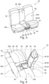
- Figure 1 shows an interior 10 of a vehicle 12.
- the vehicle 12 comprises a driver front seat 14 and a passenger front seat 16.
- the driver front seat 14 and the passenger front seat 16 are located in a first row of seats in the vehicle 12.
- a lower portion of the gap 18 is occupied by a center storage compartment 20 or center console. Above the center storage compartment 20, there is a free space 22.
- the vehicle 12 also comprises a seat assembly 24.
- the seat assembly 24 is also arranged in the interior 10 of the vehicle 12.
- the seat assembly 24 is a rear bench seat assembly. It is arranged in a second row of seats in the interior 10 of the vehicle 12.
- the seat assembly 24 comprises three sitting zones 26a, 26b, 26c being arranged side-by-side along a width direction W of the rear bench seat assembly.
- the sitting zones 26a and 26c are configured to receive an adult sitting on the seat assembly 24, i.e. on the rear bench assembly.
- the middle seat i.e. the sitting zone 26b being arranged between the two remaining sitting zones 26a, 26c is configured to receive a child. In this configuration, a portion of the back rest for the child extends into the free space 22.
- the middle seat or the sitting zone 26b may be reconfigured such that it is configured to receive an adult sitting on sitting zone 26b.
- the module comprising the back rest for the child is slidably moved towards the back rest of the rear bench assembly, i.e. the back rest for the adult. This is illustrated by arrow A2.
- the seat assembly 24 is in a configuration in which it may receive three adults, one on each sitting zone 26a, 26b, 26c.
- a state of the seat assembly 24 in which the sitting zone 26b is configured to receive an adult will be designated as a primary state.
- a state of the seat assembly 24 in which the sitting zone 26b is configured to receive a child will be designated as a secondary state.
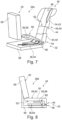
- the seat assembly 24 and especially sitting zone 26b will be explained in more detail with reference to the examples shown in Figures 3 to 5 .
- the seat assembly 24 comprises a back rest part 28 having a primary back rest surface 30.
- the primary back rest surface 30 is configured to support a back of an adult sitting on the seat assembly 24.
- the seat assembly 24 comprises a sitting module 32.
- the sitting module 32 comprises a first part 34, a second part 36 and a third part 38.
- the first part comprises a first portion 40 and a second portion 42.
- the first portion 40 and the second portion are translatorily movable with respect to one another. To this end, the first portion 40 and the second portion 42 are connected via a translation mechanism 44.
- the translation mechanism 44 comprises a bar-shaped first means which is connected to the second portion 42 and a corresponding channel-shaped second means which is provided on the first portion 40.
- the channel-shaped second means is configured to slidably receive the bar-shaped first means.
- the second portion 42 carries a secondary head rest surface 46 for supporting a head of the child sitting on the seat assembly 24.
- the first part 34 more precisely the first portion 40 of the first part 34, carries a primary functional surface 48.
- the primary functional surface 48 is a primary sitting surface 50 being configured to support a bottom and a portion of the legs of an adult sitting on the seat assembly 24, if the seat assembly 24 is in the primary state.
- the first part 34 more precisely the first portion 40 of the first part 34, carries a secondary back rest surface 52 being configured to support a back of a child sitting on the seat assembly 24, if the seat assembly 24 is in the secondary state.
- the primary functional surface 48 and the secondary back rest surface 52 are arranged on opposite sides of the first part 34, more precisely on opposite sides of the first portion 40 of the first part 34.
- the primary functional surface 48 may alternatively be a support surface 51a for supporting objects or an arm rest surface 51b being configured to support an arm of an adult. These variants are illustrated in Figure 2 (b) with dashed lines.
- the first part 34 more precisely the first portion 40 of the first part 34 is connected to the second part 36 via a pivoting mechanism 54. More generally speaking, the pivoting mechanism is cinematically interposed between the first part 34 and a second part 36.
- the pivoting mechanism 54 may for example be realized using a pivoting bolt or pin being arranged in respective openings of the first part 34 and the second part 36.
- the seat assembly 24 also comprises a sliding mechanism 56.
- the sliding mechanism is cinematically interposed between the first part 34 and the back rest part 28.
- the sliding mechanism 56 is arranged between the second part and a base component 58 of the seat assembly 24.
- the base component 58 of the seat assembly 24 may be formed by a structural component of the vehicle 12.
- the second part 36 may slide with respect to the base component 58. Since the first part 34 is pivotably connected to the second part 36, also the first part 34 may slide with respect to the base component 58. Moreover, the back rest part 28 is fixedly connected to the base component 58.
- a secondary sitting surface 60 is provided on the third part 38.
- the secondary sitting surface 60 is configured to support a bottom and a portion of the legs of the child sitting on the seat assembly 24, if the seat assembly 24 is in the secondary state.
- the third part 38 is pivotably supported on the first part 34.
- the seat assembly 24 can assume a primary state in which the primary functional surface 48 is operational. Since in the present example, the primary functional surface 48 is a primary sitting surface 50, an adult may sit on the seat assembly 24 if it is in the primary state.
- the primary sitting surface 50 may support the bottom and a portion of the legs of the adult. Additionally, the primary back rest surface 30 may support the back of the adult.
- the first part 34 and the third part 38 are folded onto the second part 36 such that the secondary back rest surface 52 faces the second part 36.
- the secondary sitting surface 60 faces the secondary back rest surface 52.
- an end portion of the first part 34 is arranged below a lower end of the back rest part 28.
- a blocking surface 62 is arranged and the end portion of the first part 34 is arranged adjacent to the blocking surface 62. In this position, the first part 34 is blocked from pivoting with respect to the second part 36. In other words, the pivoting mechanism 54 is blocked.
- the seat assembly 24 can assume a secondary state in which the seat assembly 24 is configured to receive a child.
- the secondary back rest surface 52 at least partially faces the primary back rest surface 30.
- the secondary sitting surface 60 generally faces upwards. This means that a normal on the secondary sitting surface 60 has a component being oriented upwards.
- the seat assembly 24 may be moved from the primary state into the secondary state using a method for transferring a seat assembly for a vehicle from a primary state in which a primary functional surface of the seat assembly is operational into a secondary state in which the seat assembly is configured to receive a child.
- the first part 34 and the second part 36 are translatorily moved away from the back rest part 28 using the sliding mechanism 56.
- the first part 34 is pivoted with respect to the second part 36 such that the primary back rest surface 30 and the secondary back rest surface 52 face each other.
- the seat assembly 24 may also be moved from the secondary state into the primary state using a method for transferring a seat assembly for a vehicle from a secondary state in which the seat assembly is configured to receive a child into a primary state in which a primary functional surface of the seat assembly is operational.
- the third part 38 is folded up such that the secondary sitting surface 60 faces the secondary back rest surface 52.
- the second portion 42 of the first part 34 is moved as close as possible to the first portion 40 of the first part 34.
- the first part 34 is pivoted with respect to the second part 36 such that the secondary back rest surface 52 faces the second part.
- the first part 34 and the second part 36 are slid until an end portion of the first part 34 is arranged adjacent to the blocking surface 62.
- transfers between the primary state and the secondary state and between the secondary state in the primary states may be performed manually. This means that the method as mentioned above may be performed manually.
- At least one of the pivoting mechanism 54 and the sliding mechanism 56 may comprise a respective drive means 54a, 56a. Since the drive means 54a, 56a are optional they are represented in dashed lines in Figure 5 .
- both the pivoting mechanism 54 and the sliding mechanism 56 comprise position holding means respectively. Consequently, the pivoting mechanism 54 and the sliding mechanism 56 can be locked in a desired position.
- Figures 6 to 8 show a further example of a seat assembly 24.
- the second part 36 comprises a first portion 64 and a second portion 66.
- the first portion 64 and the second portion 66 are pivotably connected, e.g. by means of a bolt or pin.
- the secondary sitting surface 60 is provided on the second portion 66 of the second part 36.
- the first portion 64 of the second part 36 is connected to the sliding mechanism 56.
- Figure 9 shows a further example of the seat assembly 24.
- the secondary sitting surface 60 is provided on the first portion 40 of the first part 34. This means that an angle between the secondary sitting surface 60 and the secondary back rest surface 52 is fixed.
- the seat assembly 24 of Figure 9 comprises a holding bar 68.
- the holding bar 68 connects the first part 34 and the second part 36.
- a first end of the holding bar 68 is pivotably connected to the first part 34.
- a second end of the holding bar 68 is slidably connected to the second part 36.
- the holding bar 68 provides further stability to the seat assembly 24. Especially, the holding bar 68 prevents the seat assembly 24 from collapsing if it is in the secondary state and the vehicle 12 is involved in an accident.
- a holding bar 68 may be provided on each side of the sitting module 32.
- FIG. 10 Another example of the seat assembly 24 is shown in Figure 10 .
- a holding bar 68 is provided.
- first end of the holding bar 68 is slidably connected to the first part 34 and the second end of the holding bar is slidably connected to the second part 36.
- an angle of the secondary back rest surface 52 may be adjusted within a comparatively big range (compare Figures 10 (a) and 10 (b) ).
- the holding bar 68 provides increased ability to the seat assembly 24.
- a holding bar 68 may be provided on each side of the sitting module 32.
- the holding bar 68 may comprise a pivot such that the holding bar 68 can be folded if the seat assembly 24 assumes the primary state.
- the seat assembly 24 is a rear bench seat assembly, this is not compulsory.
- the seat assembly 24 may as well be a single seat or a rear bench seat assembly for two adults, i.e. with two sitting zones.
- the seat assembly 24 comprises a primary seatbelt arrangement which is operational if the seat assembly is in the primary state and which is configured to secure an adult.
- the seat assembly 24 comprises a secondary seatbelt arrangement which is operational if the seat assembly 24 is in a secondary state.
- the secondary seat belt arrangement is configured to secure a child.
- the secondary seatbelt arrangement may comprise a five-point seatbelt. For the ease of representation, none of the primary seatbelt assembly and the secondary seatbelt assembly is shown in the Figures.
- the primary state may also be designated as a folded state, wherein the secondary state may be designated as an unfolded state.
Abstract
The disclosure relates to a seat assembly (24) for a vehicle. The seat assembly (24) comprises a back rest part (28) having a primary back rest surface (30) being configured to support a back of an adult sitting and a sitting module (32). The sitting module (32) comprises a first part (34) and a second part (36), wherein the first part (34) carries a primary functional surface (48) and a secondary back rest surface (52) being configured to support a back of a child. The sitting module (32) comprises a pivoting mechanism (54) and a sliding mechanism. The pivoting mechanism (54) is kinematically interposed between the first part (34) and the second part (36) and the sliding mechanism is kinematically interposed between the first part (34) and the back rest part (28) such that the seat assembly (24) may selectively assume a primary state in which the primary functional surface (48) is operational or a secondary state in which the seat assembly (24) is configured to receive a child. Moreover, a vehicle comprising such a seat assembly (24) is presented. Additionally, a method for transferring a seat assembly (24) from a primary state into a secondary state and a method for transferring a seat assembly (24) from a secondary state into a primary state are explained.
Description
- The present disclosure relates to a seat assembly for a vehicle.
- Moreover, the present disclosure is directed to a vehicle comprising a driver front seat, a passenger front seat and such a seat assembly.
- Additionally, the present disclosure relates to a method for transferring a seat assembly for a vehicle from a primary state in which a primary functional surface of the seat assembly is operational into a secondary state in which the seat assembly is configured to receive a child.
- Furthermore, the present disclosure is directed to a method for transferring a seat assembly for a vehicle from a secondary state in which the seat assembly is configured to receive a child into a primary state in which a primary functional surface of the seat assembly is operational.
- Seat assemblies which can assume different states in order to provide different functionalities are known in the art. Such seat assemblies may be called multifunctional.
- Examples of such seat assemblies can be selectively transferred between a state in which the seat assembly can be used by an adult and a state in which the seat assembly can be used by a child. This is especially convenient in cases in which such a seat assembly is provided in a rental car. Then, the user of the rental car does not need to bring an appropriate child seat if he or she is traveling together with the child. On the other hand, if the rental car is used by adults only, the space inside the rental car is not limited by unused child seats which are provided for other users potentially traveling with children.
- It is an objective of the present disclosure to further improve such multifunctional seat assemblies. Especially, the seat assemblies shall be safe and easy to use in each of the states that can be assumed by the seat assembly.
- The problem is at least partially solved or alleviated by the subject matter of the independent claims of the present disclosure, wherein further examples are incorporated in the dependent claims.
- According to a first aspect, there is provided a seat assembly for a vehicle. The seat assembly comprises a back rest part having a primary back rest surface being configured to support a back of an adult sitting on the seat assembly and a sitting module comprising a first part and a second part. The first part carries a primary functional surface and a secondary back rest surface being configured to support a back of a child sitting on the seat assembly. The primary functional surface and the secondary back rest surface are arranged on opposite sides of the first part. The sitting module comprises a pivoting mechanism and a sliding mechanism. The pivoting mechanism is kinematically interposed between the first part and the second part and the sliding mechanism is kinematically interposed between the first part and the back rest part such that the seat assembly may selectively assume a primary state in which the primary functional surface is operational or a secondary state in which the seat assembly is configured to receive a child. In the present context, the seat assembly is configured to be used by an adult in the primary state. All components being designated with the term primary are, thus, configured to provide a functionality for an adult. In contrast thereto, the seat assembly is configured to be used by a child in the secondary state. All components being designated with the term secondary are, thus, configured to provide a functionality for a child. Consequently, in the primary state and the secondary state, the seat assembly provides two different functionalities. Since the primary state and the secondary state may be selectively assumed, the seat assembly may be transferred from the primary state into the secondary state and from the secondary state into the primary state as needed. Due to the fact that the seat assembly comprises both the pivoting mechanism and a sliding mechanism, the components of the seat assembly can be adjusted to be in a safe and comfortable position both in the primary state and in the secondary state. As compared to known solutions, a comparatively large space, especially a comparatively large leg space, may be provided for the child if the seat assembly is in the secondary state.
- It is noted that the primary back rest surface which is configured to support a back of an adult, is at least configured to perform this functionality with respect to its size and shape.
- Analogously, the secondary back rest surface which is configured to support a back of a child, is at least configured to perform this functionality with respect to its size and shape.
- Since the seat assembly according to the present disclosure is configured to be used in a vehicle, it may also be called a vehicle seat assembly.
- In an example, the sliding mechanism may comprise a rail and a block-shaped element being guided in the rail. It is also possible to use a known sliding mechanism which is used for the longitudinal adjustment of a position of a front seat.
- In another example, the pivoting mechanism comprises a pivot axis which extends through corresponding openings of the parts to be pivoted. Alternatively, one of the parts to be pivoted comprises an opening and the other part to be pivoted comprises a protrusion which extends into the opening.
- According to an example, the seat assembly comprises a primary seatbelt arrangement which is configured to secure an adult to the seat assembly. The primary seatbelt arrangement may comprise a three-point seatbelt.
- According to a further example, the seat assembly comprises a secondary seatbelt arrangement which is configured to secure a child to the seat assembly. The secondary seatbelt arrangement may comprise a five-point seatbelt.
- In an example, the primary functional surface is a primary sitting surface being configured to support a bottom and a portion of the legs of an adult sitting on the seat assembly. Alternatively, the primary functional surface is a support surface for supporting objects. Further alternatively, the primary functional surface is an arm rest surface being configured to support an arm of an adult. In this alternative, the arm rest surface is configured to support an arm of an adult sitting next to the seat assembly according to the present disclosure. Thus, a wide variety of functionalities can be provided for an adult using the seat assembly.
- In an example, the secondary back rest surface faces the second part in the primary state. Consequently, the seat assembly may assume a compact configuration. Additionally or alternatively, an end portion of the first part is arranged adjacent to a blocking surface of the back rest part in the primary state. This has the effect that the pivoting mechanism is blocked. In other words, the end portion of the first part is arranged under the back rest part. Thus, the pivoting mechanism cannot move in an undesired manner. Moreover, in such a configuration, the first part can be comparatively long. Consequently, also the secondary back rest surface can be comparatively long. This has the advantage that also older children are able to sit comfortably and safely on the seat assembly if it is in the secondary state.
- In an example, the secondary back rest surface at least partially faces the primary back rest surface in the secondary state. Consequently, a child that is using the seat assembly is oriented rearwards. This is a particularly safe manner for transporting children in vehicles.
- In an example, a secondary sitting surface being configured to support a bottom and a portion of the legs of the child sitting on the seat assembly is located on the second part. Thus, a child using the seat assembly is sitting on a comparatively low level. In other words, the child is sitting close to a vehicle structure on which the seat assembly is arranged.
- In an example, the second part comprises a first portion and a second portion, wherein one out of the first portion and the second portion carries the secondary sitting surface. Moreover, the first portion and the second portion are pivotably connected. Thus, an orientation of the secondary sitting surface can be adapted by pivoting the first portion with respect to the second portion. Consequently, the secondary sitting surface can be adapted to a child's needs. This enhances comfort and safety.
- In an example, a secondary sitting surface being configured to support a bottom and a portion of the legs of the child sitting on the seat assembly is located on a third part, the third part being pivotably supported on the first part. Also in this example, an orientation of the secondary sitting surface can be adjusted by pivoting the third part with respect to the first part. Consequently, the secondary sitting surface can be adapted to a child's needs. This enhances comfort and safety.
- In an example, the first part comprises a first portion and a second portion. The first portion and the second portion are translatorily movable with respect to one another. The translatory movement may be guided by a guiding means, for example a guiding rail. Since the first part carries the secondary back rest surface, a length of the secondary back rest surface can be adjusted by translatory removing the first portion and the second portion relative to each other. Consequently, also the secondary back rest surface can be adapted to a child's needs. This enhances comfort and safety.
- In an example, one out of the first portion and the second portion is kinematically connected to the second part via the pivoting mechanism and the other one out of the first portion and the second portion carries a secondary head rest surface for supporting a head of the child sitting on the seat assembly. In other words, an adjustable headrest is provided for the child. The head rest surface may be shaped concavely. Thus, a child's head may be supported in a safe and comfortable manner.
- In an example, the seat assembly is a rear bench seat assembly with three sitting zones. The three sitting zones are arranged side by side along a width direction of the rear bench seat assembly. Each of the three sitting zones is configured to receive an adult sitting on the rear bench assembly. The sitting module and the primary sitting surface are associated with one of the sitting zones being arranged between the two remaining sitting zones. In other words, the sitting module and the primary sitting surface are associated with a middle seat of the rear bench seat assembly. Thus, the middle seat can be in a primary state or in a secondary state as defined above.
- In an example, at least one of the pivoting mechanism and the sliding mechanism comprises a respective drive means. This means that at least one of the pivoting mechanism and the sliding mechanism may be at least partly driven in an automatic manner. This means that the seat assembly can be transferred between the primary state and the secondary state at least in a partially automatic manner. This is comfortable for a user of the seat assembly.
- In an example, the drive means for the pivoting mechanism comprises at least one electric motor and a gear drive.
- In another example, the drive means for the sliding mechanism comprises at least one electric motor and a rack and pinion mechanism being drivingly connected thereto.
- In an example, at least one of the pivoting mechanism and the sliding mechanism comprises a position holding means being configured to lock the pivoting mechanism or the sliding mechanism in a desired position. Consequently, at least one of the pivoting mechanism and the sliding mechanism can be securely held in the desired relative position of the parts being connected by means of the pivoting mechanism or the sliding mechanism respectively. Consequently, in each of the primary state of the secondary state, the seat assembly can assume a configuration that is both comfortable and safe for a given adult or for a given child.
- In an example, the position holding means may comprise a pair of toothings which are configured to engage each other in different relative positions. Alternatively, a number of holes may be provided on one of the movable parts and a pin being configured to engage one of the holes may be provided on the other one of the movable parts. The holes may be arranged in a regular pattern.
- According to a second aspect, there is provided a vehicle comprising a driver front seat, a passenger front seat and a seat assembly according to the present disclosure. A gap is provided between the driver front seat and the passenger front seat. Moreover, the first part of the seat assembly at least partially extends into the gap if the seat assembly is in the secondary state. Alternatively, a width of the gap is larger than a width of the first part and the first part is arranged adjacent to the gap when the seat assembly is in the secondary state. Thus, the first part may use the space between the driver front seat and the passenger front seat when the seat assembly is in the secondary state. Consequently, the seat assembly provides a comparatively big space for a child sitting thereon. Thus, the child may sit in a very comfortable manner. In case of an accident, especially a rear-end collision, the front driver seat and the front passenger seat may be moved. However, such a movement will not reduce the space for a child sitting in a seat assembly which assumes the secondary state. In case of an accident, the front driver seat and the front passenger seat will move backwards without interfering with the first part of the seat assembly. Thus, the child is very safe. The same applies in the second alternative, wherein the first part is arranged adjacent to the gap such that in case of an accident, the first part can move into the gap between the front driver seat and the front passenger seat.
- According to a third aspect, there is provided a method for transferring a seat assembly for a vehicle from a primary state in which a primary functional surface of the seat assembly is operational, into a secondary state in which the seat assembly is configured to receive a child. The seat assembly comprises a back rest part having a primary back rest surface being configured to support a back of an adult sitting on the seat assembly and a sitting module comprising a first part and a second part, wherein the first part carries the primary functional surface and a secondary back rest surface being configured to support a back of a child sitting on the seat assembly. The primary functional surface and the secondary back rest surface are arranged on opposite sides of the first part. The method comprises:
- translatorily moving at least the first part away from the back rest part, and
- pivoting the first part with respect to the second part such that the primary back rest surface and the secondary back rest surface face each other.
- Thus, the seat assembly may be transferred from the primary state into the secondary state in a very simple manner. The transformation of the a seat assembly being configured to receive an adult into a seat assembly being configured to receive a child is, thus, quick and easy.
- It is noted that the method for transferring a seat assembly for a vehicle from a primary state into a secondary state may be carried out using the seat assembly according to the present disclosure.
- According to a fourth aspect, there is provided a method for transferring a seat assembly for a vehicle from a secondary state in which the seat assembly is configured to receive a child, into a primary state in which a primary functional surface of the seat assembly is operational. The seat assembly comprises a back rest part having a primary back rest surface being configured to support a back of an adult sitting on the seat assembly and a sitting module comprising a first part and a second part. The first part carries the primary functional surface and a secondary back rest surface being configured to support a back of a child sitting on the seat assembly. The primary functional surface and the secondary back rest surface are arranged on opposite sides of the first part. The method comprises:
- pivoting the first part with respect to the second part such that the secondary back rest surface faces the second part, and
- translatorily moving at least the first part towards the back rest part.
- Thus, the seat assembly may be transferred from the secondary state into the primary state in a very simple manner. The transformation of the seat assembly being configured to receive a child into a seat assembly being configured to receive an adult is, thus, quick and easy.
- It is noted that the method for transferring a seat assembly for a vehicle from a secondary state into a primary state may be carried out using the seat assembly according to the present disclosure.
- It should be noted that the above examples may be combined with each other irrespective of the aspect involved.
- These and other aspects of the present disclosure will become apparent from and elucidated with reference to the examples described hereinafter.
- Examples of the disclosure will be described in the following with reference to the following drawings.
- Figure 1
- shows an interior of a vehicle according to the present disclosure comprising a seat assembly according to the present disclosure which can be transferred from a primary state into a secondary state and vice versa using methods according to the present disclosure, wherein the seat assembly is in a secondary state,
- Figure 2
- schematically shows the seat assembly of
Figure 1 in two different stages while the seat assembly is transferred into a primary state, - Figure 3
- shows the seat assembly of
Figures 1 and 2 in the primary state, - Figure 4
- shows the seat assembly of
Figures 1 to 3 in the secondary state, - Figure 5
- schematically illustrates the components of the seat assembly according to
Figures 1 to 4 and their connections, - Figure 6
- shows a seat assembly according to another example of the present disclosure, wherein the seat assembly is in a primary state,
- Figure 7
- shows the seat assembly of
Figure 6 in a secondary state, - Figure 8
- schematically illustrates the components of the seat assembly according to
Figures 6 and7 and their connections, - Figure 9
- shows a seat assembly according to a further example of the present disclosure, wherein the seat assembly is in a secondary state, and
- Figure 10
- shows a seat assembly according to another example of the present disclosure, wherein the seat assembly is in a secondary state.
- The Figures are merely schematic representations and serve only to illustrate examples of the disclosure. Identical or equivalent elements are in principle provided with the same reference signs.
-
Figure 1 shows an interior 10 of a vehicle 12. - The vehicle 12 comprises a
driver front seat 14 and apassenger front seat 16. - The
driver front seat 14 and thepassenger front seat 16 are located in a first row of seats in the vehicle 12. - Between the
driver front seat 14 and thepassenger front seat 16, there is agap 18. - A lower portion of the
gap 18 is occupied by acenter storage compartment 20 or center console. Above thecenter storage compartment 20, there is afree space 22. - The vehicle 12 also comprises a
seat assembly 24. Theseat assembly 24 is also arranged in the interior 10 of the vehicle 12. - In the present example, the
seat assembly 24 is a rear bench seat assembly. It is arranged in a second row of seats in the interior 10 of the vehicle 12. - The
seat assembly 24 comprises three sittingzones - In the configuration shown in
Figure 1 , the sittingzones seat assembly 24, i.e. on the rear bench assembly. - The middle seat, i.e. the sitting
zone 26b being arranged between the two remaining sittingzones free space 22. - However, the middle seat or the sitting
zone 26b may be reconfigured such that it is configured to receive an adult sitting on sittingzone 26b. - This reconfiguration is illustrated in
Figure 2 . First, the back rest of the child's needs to be folded down. This is illustrated by arrow A1 (cf.Figure 2(a) ). - Thereafter, the module comprising the back rest for the child is slidably moved towards the back rest of the rear bench assembly, i.e. the back rest for the adult. This is illustrated by arrow A2.
- Consequently, the
seat assembly 24 is in a configuration in which it may receive three adults, one on each sittingzone - In the following, a state of the
seat assembly 24 in which the sittingzone 26b is configured to receive an adult will be designated as a primary state. A state of theseat assembly 24 in which the sittingzone 26b is configured to receive a child will be designated as a secondary state. - The
seat assembly 24 and especially sittingzone 26b will be explained in more detail with reference to the examples shown inFigures 3 to 5 . - The
seat assembly 24 comprises aback rest part 28 having a primaryback rest surface 30. - The primary
back rest surface 30 is configured to support a back of an adult sitting on theseat assembly 24. - Moreover, the
seat assembly 24 comprises a sittingmodule 32. - The sitting
module 32 comprises afirst part 34, asecond part 36 and athird part 38. - The first part comprises a first portion 40 and a second portion 42.
- The first portion 40 and the second portion are translatorily movable with respect to one another. To this end, the first portion 40 and the second portion 42 are connected via a
translation mechanism 44. - The
translation mechanism 44 comprises a bar-shaped first means which is connected to the second portion 42 and a corresponding channel-shaped second means which is provided on the first portion 40. The channel-shaped second means is configured to slidably receive the bar-shaped first means. - In the present example, the second portion 42 carries a secondary
head rest surface 46 for supporting a head of the child sitting on theseat assembly 24. - Additionally, the
first part 34, more precisely the first portion 40 of thefirst part 34, carries a primary functional surface 48. In the present example, the primary functional surface 48 is a primary sitting surface 50 being configured to support a bottom and a portion of the legs of an adult sitting on theseat assembly 24, if theseat assembly 24 is in the primary state. - Furthermore, the
first part 34, more precisely the first portion 40 of thefirst part 34, carries a secondaryback rest surface 52 being configured to support a back of a child sitting on theseat assembly 24, if theseat assembly 24 is in the secondary state. - The primary functional surface 48 and the secondary
back rest surface 52 are arranged on opposite sides of thefirst part 34, more precisely on opposite sides of the first portion 40 of thefirst part 34. - It is noted that in other variants of the
seat assembly 24, the primary functional surface 48 may alternatively be asupport surface 51a for supporting objects or anarm rest surface 51b being configured to support an arm of an adult. These variants are illustrated inFigure 2 (b) with dashed lines. - The
first part 34, more precisely the first portion 40 of thefirst part 34 is connected to thesecond part 36 via apivoting mechanism 54. More generally speaking, the pivoting mechanism is cinematically interposed between thefirst part 34 and asecond part 36. Thepivoting mechanism 54 may for example be realized using a pivoting bolt or pin being arranged in respective openings of thefirst part 34 and thesecond part 36. - The
seat assembly 24 also comprises a slidingmechanism 56. The sliding mechanism is cinematically interposed between thefirst part 34 and theback rest part 28. - In the present example, the sliding
mechanism 56 is arranged between the second part and abase component 58 of theseat assembly 24. Thebase component 58 of theseat assembly 24 may be formed by a structural component of the vehicle 12. - Consequently, the
second part 36 may slide with respect to thebase component 58. Since thefirst part 34 is pivotably connected to thesecond part 36, also thefirst part 34 may slide with respect to thebase component 58. Moreover, theback rest part 28 is fixedly connected to thebase component 58. - A secondary sitting
surface 60 is provided on thethird part 38. - The secondary sitting
surface 60 is configured to support a bottom and a portion of the legs of the child sitting on theseat assembly 24, if theseat assembly 24 is in the secondary state. - The
third part 38 is pivotably supported on thefirst part 34. - Consequently, the
seat assembly 24 can assume a primary state in which the primary functional surface 48 is operational. Since in the present example, the primary functional surface 48 is a primary sitting surface 50, an adult may sit on theseat assembly 24 if it is in the primary state. - In more detail, the primary sitting surface 50 may support the bottom and a portion of the legs of the adult. Additionally, the primary
back rest surface 30 may support the back of the adult. - In the primary state, the
first part 34 and thethird part 38 are folded onto thesecond part 36 such that the secondaryback rest surface 52 faces thesecond part 36. - Moreover, the secondary sitting
surface 60 faces the secondaryback rest surface 52. - Additionally, in the primary state, an end portion of the
first part 34, more precisely an end portion of the first portion 40 of thefirst part 34, is arranged below a lower end of theback rest part 28. - On this lower end, a blocking
surface 62 is arranged and the end portion of thefirst part 34 is arranged adjacent to the blockingsurface 62. In this position, thefirst part 34 is blocked from pivoting with respect to thesecond part 36. In other words, thepivoting mechanism 54 is blocked. - Alternatively, the
seat assembly 24 can assume a secondary state in which theseat assembly 24 is configured to receive a child. - In the secondary state, the secondary
back rest surface 52 at least partially faces the primaryback rest surface 30. - Moreover, the secondary sitting
surface 60 generally faces upwards. This means that a normal on the secondary sittingsurface 60 has a component being oriented upwards. - The
seat assembly 24 may be moved from the primary state into the secondary state using a method for transferring a seat assembly for a vehicle from a primary state in which a primary functional surface of the seat assembly is operational into a secondary state in which the seat assembly is configured to receive a child. - Thus, starting from the primary state, in a first step, the
first part 34 and thesecond part 36 are translatorily moved away from theback rest part 28 using the slidingmechanism 56. - This has the effect that the end portion of the
first part 34 is moved away from the blockingsurface 62. - Once this end portion is not located under the
back rest part 28 anymore, thefirst part 34 is pivoted with respect to thesecond part 36 such that the primaryback rest surface 30 and the secondaryback rest surface 52 face each other. - The
seat assembly 24 may also be moved from the secondary state into the primary state using a method for transferring a seat assembly for a vehicle from a secondary state in which the seat assembly is configured to receive a child into a primary state in which a primary functional surface of the seat assembly is operational. - To this end, the
third part 38 is folded up such that the secondary sittingsurface 60 faces the secondaryback rest surface 52. - If necessary, the second portion 42 of the
first part 34 is moved as close as possible to the first portion 40 of thefirst part 34. - Then, the
first part 34 is pivoted with respect to thesecond part 36 such that the secondaryback rest surface 52 faces the second part. - Thereafter, the
first part 34 and thesecond part 36 are translatorily moved towards theback rest part 28. To this end, the sliding mechanism in 56 is used. - The
first part 34 and thesecond part 36 are slid until an end portion of thefirst part 34 is arranged adjacent to the blockingsurface 62. - It is noted that transfers between the primary state and the secondary state and between the secondary state in the primary states may be performed manually. This means that the method as mentioned above may be performed manually.
- Alternatively, at least one of the
pivoting mechanism 54 and the slidingmechanism 56 may comprise a respective drive means 54a, 56a. Since the drive means 54a, 56a are optional they are represented in dashed lines inFigure 5 . - Moreover, it is understood that both the
pivoting mechanism 54 and the slidingmechanism 56 comprise position holding means respectively. Consequently, thepivoting mechanism 54 and the slidingmechanism 56 can be locked in a desired position. -
Figures 6 to 8 show a further example of aseat assembly 24. - In the following, only the differences with respect to the examples of
Figures 1 to 5 will be explained. Same or corresponding parts will be provided with the same reference signs. - In the example of
Figures 6 to 8 , there is no third part. - Instead, the
second part 36 comprises a first portion 64 and a second portion 66. - The first portion 64 and the second portion 66 are pivotably connected, e.g. by means of a bolt or pin.
- The secondary sitting
surface 60 is provided on the second portion 66 of thesecond part 36. - The first portion 64 of the
second part 36 is connected to the slidingmechanism 56. - Beyond that, reference is made to the above explanations.
-
Figure 9 shows a further example of theseat assembly 24. - As before, only the differences with respect to the examples that have already been explained in connection with
Figures 1 to 8 will be mentioned. - In the example of
Figure 9 , the secondary sittingsurface 60 is provided on the first portion 40 of thefirst part 34. This means that an angle between the secondary sittingsurface 60 and the secondaryback rest surface 52 is fixed. - Furthermore, the
seat assembly 24 ofFigure 9 comprises a holdingbar 68. - The holding
bar 68 connects thefirst part 34 and thesecond part 36. - In this context, a first end of the holding
bar 68 is pivotably connected to thefirst part 34. A second end of the holdingbar 68 is slidably connected to thesecond part 36. - Consequently, the holding
bar 68 provides further stability to theseat assembly 24. Especially, the holdingbar 68 prevents theseat assembly 24 from collapsing if it is in the secondary state and the vehicle 12 is involved in an accident. - It is noted that a holding
bar 68 may be provided on each side of the sittingmodule 32. - Beyond that, reference is made to the above explanations.
- Another example of the
seat assembly 24 is shown inFigure 10 . - This example is a variant of the example of
Figure 9 . Consequently, only the differences with respect to this example will be explained. - Again, a holding
bar 68 is provided. - However, now the first end of the holding
bar 68 is slidably connected to thefirst part 34 and the second end of the holding bar is slidably connected to thesecond part 36. - Due to this configuration, an angle of the secondary
back rest surface 52 may be adjusted within a comparatively big range (compareFigures 10 (a) and 10 (b) ). - Again, the holding
bar 68 provides increased ability to theseat assembly 24. - As before, a holding
bar 68 may be provided on each side of the sittingmodule 32. - Optionally, the holding
bar 68 may comprise a pivot such that the holdingbar 68 can be folded if theseat assembly 24 assumes the primary state. - It is noted that even though in the above examples the
seat assembly 24 is a rear bench seat assembly, this is not compulsory. Theseat assembly 24 may as well be a single seat or a rear bench seat assembly for two adults, i.e. with two sitting zones. - It is additionally noted that the
seat assembly 24 comprises a primary seatbelt arrangement which is operational if the seat assembly is in the primary state and which is configured to secure an adult. Moreover, theseat assembly 24 comprises a secondary seatbelt arrangement which is operational if theseat assembly 24 is in a secondary state. The secondary seat belt arrangement is configured to secure a child. The secondary seatbelt arrangement may comprise a five-point seatbelt. For the ease of representation, none of the primary seatbelt assembly and the secondary seatbelt assembly is shown in the Figures. - Additionally, since in the primary state the
seat assembly 24 is more compact than in the secondary state, the primary state may also be designated as a folded state, wherein the secondary state may be designated as an unfolded state. - Other variations to the disclosed examples can be understood and effected by those skilled in the art in practicing the claimed disclosure, from the study of the drawings, the disclosure, and the appended claims. In the claims the word "comprising" does not exclude other elements or steps and the indefinite article "a" or "an" does not exclude a plurality. A single processor or other unit may fulfill the functions of several items or steps recited in the claims. The mere fact that certain measures are recited in mutually different dependent claims does not indicate that a combination of these measures cannot be used to advantage. Any reference signs in the claims should not be construed as limiting the scope of the claims.
-
- 10
- interior
- 12
- vehicle
- 14
- driver front seat
- 16
- passenger front seat
- 18
- gap
- 20
- center storage compartment
- 22
- free space
- 24
- seat assembly
- 26a
- sitting zone
- 26b
- sitting zone
- 26c
- sitting zone
- 28
- back rest part
- 30
- primary back rest surface
- 32
- sitting module
- 34
- first part
- 36
- second part
- 38
- third part
- 40
- first portion of the first part
- 42
- second portion of the first part
- 44
- translation mechanism
- 46
- secondary head rest surface
- 48
- primary functional surface
- 50
- primary sitting surface
- 51a
- support surface
- 51b
- arm rest surface
- 52
- secondary back rest surface
- 54
- pivoting mechanism
- 54a
- drive means of the pivoting mechanism
- 56
- sliding mechanism
- 56a
- drive means of the sliding mechanism
- 58
- base component
- 60
- secondary sitting surface
- 62
- blocking surface
- 64
- first portion of the second part
- 66
- second portion of the second part
- 68
- holding bar
- A1
- arrow
- A2
- arrow
- W
- width direction
Claims (15)
- A seat assembly (24) for a vehicle, comprisinga back rest part (28) having a primary back rest surface (30) being configured to support a back of an adult sitting on the seat assembly (24) anda sitting module (32) comprising a first part (34) and a second part (36),wherein the first part (34) carries a primary functional surface (48) and a secondary back rest surface (52) being configured to support a back of a child sitting on the seat assembly (24), the primary functional surface (48) and the secondary back rest surface (52) being arranged on opposite sides of the first part (34),wherein the sitting module (32) comprises a pivoting mechanism (54) and a sliding mechanism (56), the pivoting mechanism (56) being kinematically interposed between the first part (34) and the second part (36) and the sliding mechanism (56) being kinematically interposed between the first part (34) and the back rest part (28) such that the seat assembly (24) may selectively assume a primary state in which the primary functional surface (48) is operational or a secondary state in which the seat assembly (24) is configured to receive a child.
- The seat assembly (24) according to claim 1,wherein the primary functional surface (48) is a primary sitting surface (50) being configured to support a bottom and a portion of the legs of an adult sitting on the seat assembly (24), orwherein the primary functional surface (48) is a support surface for supporting objects, orwherein the primary functional surface (48) is an arm rest surface being configured to support an arm of an adult.
- The seat assembly (24) according to any one of the preceding claims, wherein in the primary state, the secondary back rest surface (52) faces the second part (36) and/or wherein in the primary state, an end portion of the first part (34) is arranged adjacent to a blocking surface (62) of the back rest part (28) such that the pivoting mechanism (54) is blocked.
- The seat assembly (24) according to any one of the preceding claims, wherein in the secondary state, the secondary back rest surface (52) at least partially faces the primary back rest surface (30).
- The seat assembly (24) according to any one of the preceding claims, wherein a secondary sitting surface (60) being configured to support a bottom and a portion of the legs of the child sitting on the seat assembly (24) is located on the second part (36).
- The seat assembly (24) according to claim 6, wherein the second part (36) comprises a first portion (64) and a second portion (66), wherein one out of the first portion (64) and the second portion (66) carries the secondary sitting surface (60) and the first portion (64) and the second portion (66) are pivotably connected.
- The seat assembly (24) according to any one of claims 1 to 5, wherein a secondary sitting surface (60) being configured to support a bottom and a portion of the legs of the child sitting on the seat assembly (24) is located on a third part (38), the third part (38) being pivotably supported on the first part (34).
- The seat assembly (24) according to any one of the preceding claims, wherein the first part (34) comprises a first portion (40) and a second portion (42), the first portion (40) and the second portion (42) being translatorily movable with respect to one another.
- The seat assembly (24) according to claim 8, wherein one out of the first portion (40) and the second portion (42) is kinematically connected to the second part (36) via the pivoting mechanism (54) and the other one out of the first portion (40) and the second portion (42) carries a secondary head rest surface (46) for supporting a head of the child sitting on the seat assembly (24).
- The seat assembly (24) according to any one of the preceding claims, wherein the seat assembly (24) is a rear bench seat assembly with three sitting zones (26a, 26b, 26c) being arranged side by side along a width direction (W) of the rear bench seat assembly, wherein each of the three sitting zones (26a, 26b, 26c) is configured to receive an adult sitting on the rear bench assembly, and wherein the sitting module (32) and the primary sitting surface (50) are associated with one of the sitting zones (26a, 26b, 26c) being arranged between the two remaining sitting zones (26a, 26b, 26c).
- The seat assembly (24) according to any one of the preceding claims, wherein at least one of the pivoting mechanism (54) and the sliding mechanism (56) comprises a respective drive means (54a, 56a).
- The seat assembly (24) according to any one of the preceding claims, wherein at least one of the pivoting mechanism (54) and the sliding mechanism (56) comprises a position holding means being configured to lock the pivoting mechanism (54) or the sliding mechanism (56) in a desired position.
- A vehicle (12) comprising a driver front seat (14), a passenger front seat (16) and a seat assembly (24) according to any one of the preceding claims, wherein a gap (18) is provided between the driver front seat (14) and the passenger front seat (16),
wherein the first part (34) of the seat assembly (24) at least partially extends into the gap (18) if the seat assembly (24) is in the secondary state or wherein a width of the gap (18) is larger than a width of the first part (34) and the first part (34) is arranged adjacent to the gap (18) when the seat assembly (24) is in the secondary state. - A method for transferring a seat assembly (24) for a vehicle from a primary state in which a primary functional surface (48) of the seat assembly (24) is operational, into a secondary state in which the seat assembly (24) is configured to receive a child, wherein the seat assembly (24) comprises a back rest part (28) having a primary back rest surface (30) being configured to support a back of an adult sitting on the seat assembly (24) and a sitting module (32) comprising a first part (34) and a second part (36),
wherein the first part (34) carries the primary functional surface (48) and a secondary back rest surface (52) being configured to support a back of a child sitting on the seat assembly (24), the primary functional surface (48) and the secondary back rest surface (52) being arranged on opposite sides of the first part (34), the method comprising:- translatorily moving at least the first part (34) away from the back rest part (28), and- pivoting the first part (34) with respect to the second part (36) such that the primary back rest surface (30) and the secondary back rest surface (52) face each other. - A method for transferring a seat assembly (28) for a vehicle from a secondary state in which the seat assembly (24) is configured to receive a child, into a primary state in which a primary functional surface (48) of the seat assembly (24) is operational, wherein the seat assembly (24) comprises a back rest part (28) having a primary back rest surface (30) being configured to support a back of an adult sitting on the seat assembly (24) and a sitting module (32) comprising a first part (34) and a second part (36), wherein the first part (34) carries the primary functional surface (48) and a secondary back rest surface (52) being configured to support a back of a child sitting on the seat assembly (24), the primary functional surface (48) and the secondary back rest surface (52) being arranged on opposite sides of the first part (34), the method comprising:- pivoting the first part (34) with respect to the second part (36) such that the secondary back rest surface (52) faces the second part (36), and- translatorily moving at least the first part (34) towards the back rest part (28).
Priority Applications (2)
| Application Number | Priority Date | Filing Date | Title |
|---|---|---|---|
| EP22199555.8A EP4349645A1 (en) | 2022-10-04 | 2022-10-04 | Seat assembly for a vehicle, vehicle and methods |
| CN202311281675.3A CN117841799A (en) | 2022-10-04 | 2023-09-28 | Seat assembly for vehicle, vehicle and method |
Applications Claiming Priority (1)
| Application Number | Priority Date | Filing Date | Title |
|---|---|---|---|
| EP22199555.8A EP4349645A1 (en) | 2022-10-04 | 2022-10-04 | Seat assembly for a vehicle, vehicle and methods |
Publications (1)
| Publication Number | Publication Date |
|---|---|
| EP4349645A1 true EP4349645A1 (en) | 2024-04-10 |
Family
ID=83594204
Family Applications (1)
| Application Number | Title | Priority Date | Filing Date |
|---|---|---|---|
| EP22199555.8A Pending EP4349645A1 (en) | 2022-10-04 | 2022-10-04 | Seat assembly for a vehicle, vehicle and methods |
Country Status (2)
| Country | Link |
|---|---|
| EP (1) | EP4349645A1 (en) |
| CN (1) | CN117841799A (en) |
Citations (3)
| Publication number | Priority date | Publication date | Assignee | Title |
|---|---|---|---|---|
| FR2707567A1 (en) * | 1993-07-12 | 1995-01-20 | Peugeot | Seat for a motor vehicle which can be converted into a seat for a young child |
| WO2001005618A1 (en) * | 1999-07-15 | 2001-01-25 | Zaza International Co., Ltd. | Seat for vehicle |
| GB2436283A (en) * | 2006-03-22 | 2007-09-26 | Allan William Ullmann | Vehicle passenger seat with child seat compartment |
-
2022
- 2022-10-04 EP EP22199555.8A patent/EP4349645A1/en active Pending
-
2023
- 2023-09-28 CN CN202311281675.3A patent/CN117841799A/en active Pending
Patent Citations (3)
| Publication number | Priority date | Publication date | Assignee | Title |
|---|---|---|---|---|
| FR2707567A1 (en) * | 1993-07-12 | 1995-01-20 | Peugeot | Seat for a motor vehicle which can be converted into a seat for a young child |
| WO2001005618A1 (en) * | 1999-07-15 | 2001-01-25 | Zaza International Co., Ltd. | Seat for vehicle |
| GB2436283A (en) * | 2006-03-22 | 2007-09-26 | Allan William Ullmann | Vehicle passenger seat with child seat compartment |
Also Published As
| Publication number | Publication date |
|---|---|
| CN117841799A (en) | 2024-04-09 |
Similar Documents
| Publication | Publication Date | Title |
|---|---|---|
| US10189373B2 (en) | Seat arrangement | |
| US7438339B2 (en) | Vehicle Seat | |
| US5482349A (en) | Combination reclining and folding mechanism for automotive seat assemblies | |
| US4768827A (en) | Stowable car seat for children | |
| US5282666A (en) | Vehicle seat assembly with integrated child seat | |
| EP1787855B1 (en) | Vehicle child seat arrangement | |
| EP2402208B1 (en) | Vehicle seat device | |
| US7845724B2 (en) | Automotive seating configuration | |
| US3746389A (en) | Folding seats for automotive vehicles | |
| US5722720A (en) | Child safety seat with an anti-rebound support | |
| EP0881970B1 (en) | Seat back automatic height adjuster and recliner mechanism | |
| US3711153A (en) | Seats for motor vehicles | |
| US5056849A (en) | Limousine construction | |
| EP0151426B1 (en) | Improved vehicle provided with seats, the back rest of which can be folded down to the level of the load-carrying platform | |
| JP3380192B2 (en) | Car seat | |
| US7516999B2 (en) | Seat device for vehicle | |
| US5516194A (en) | Combination child's seat and armrest for a vehicle | |
| JP2011508703A (en) | Car seats for children | |
| EP3403874B1 (en) | A motor vehicle seating arrangement | |
| EP4349645A1 (en) | Seat assembly for a vehicle, vehicle and methods | |
| EP1461225B1 (en) | Motor vehicle seat, with a knee-rest element | |
| US7510161B2 (en) | Longitudinal guiding element for motor vehicle seat | |
| EP1442924B1 (en) | Booster cushion | |
| KR100358912B1 (en) | Rear-Seat Arm-rest of Automobile | |
| KR20040042946A (en) | Structure for mounting center seat of vehicle |
Legal Events
| Date | Code | Title | Description |
|---|---|---|---|
| PUAI | Public reference made under article 153(3) epc to a published international application that has entered the european phase |
Free format text: ORIGINAL CODE: 0009012 |
|
| STAA | Information on the status of an ep patent application or granted ep patent |
Free format text: STATUS: REQUEST FOR EXAMINATION WAS MADE |
|
| 17P | Request for examination filed |
Effective date: 20230612 |
|
| AK | Designated contracting states |
Kind code of ref document: A1 Designated state(s): AL AT BE BG CH CY CZ DE DK EE ES FI FR GB GR HR HU IE IS IT LI LT LU LV MC ME MK MT NL NO PL PT RO RS SE SI SK SM TR |