EP4349627A1 - Battery case - Google Patents
Battery case Download PDFInfo
- Publication number
- EP4349627A1 EP4349627A1 EP21942150.0A EP21942150A EP4349627A1 EP 4349627 A1 EP4349627 A1 EP 4349627A1 EP 21942150 A EP21942150 A EP 21942150A EP 4349627 A1 EP4349627 A1 EP 4349627A1
- Authority
- EP
- European Patent Office
- Prior art keywords
- battery case
- vehicle
- rib
- frame
- bracket
- Prior art date
- Legal status (The legal status is an assumption and is not a legal conclusion. Google has not performed a legal analysis and makes no representation as to the accuracy of the status listed.)
- Granted
Links
Images

Classifications
-
- B—PERFORMING OPERATIONS; TRANSPORTING
- B60—VEHICLES IN GENERAL
- B60K—ARRANGEMENT OR MOUNTING OF PROPULSION UNITS OR OF TRANSMISSIONS IN VEHICLES; ARRANGEMENT OR MOUNTING OF PLURAL DIVERSE PRIME-MOVERS IN VEHICLES; AUXILIARY DRIVES FOR VEHICLES; INSTRUMENTATION OR DASHBOARDS FOR VEHICLES; ARRANGEMENTS IN CONNECTION WITH COOLING, AIR INTAKE, GAS EXHAUST OR FUEL SUPPLY OF PROPULSION UNITS IN VEHICLES
- B60K1/00—Arrangement or mounting of electrical propulsion units
- B60K1/04—Arrangement or mounting of electrical propulsion units of the electric storage means for propulsion
-
- B—PERFORMING OPERATIONS; TRANSPORTING
- B60—VEHICLES IN GENERAL
- B60L—PROPULSION OF ELECTRICALLY-PROPELLED VEHICLES; SUPPLYING ELECTRIC POWER FOR AUXILIARY EQUIPMENT OF ELECTRICALLY-PROPELLED VEHICLES; ELECTRODYNAMIC BRAKE SYSTEMS FOR VEHICLES IN GENERAL; MAGNETIC SUSPENSION OR LEVITATION FOR VEHICLES; MONITORING OPERATING VARIABLES OF ELECTRICALLY-PROPELLED VEHICLES; ELECTRIC SAFETY DEVICES FOR ELECTRICALLY-PROPELLED VEHICLES
- B60L50/00—Electric propulsion with power supplied within the vehicle
- B60L50/50—Electric propulsion with power supplied within the vehicle using propulsion power supplied by batteries or fuel cells
- B60L50/60—Electric propulsion with power supplied within the vehicle using propulsion power supplied by batteries or fuel cells using power supplied by batteries
- B60L50/64—Constructional details of batteries specially adapted for electric vehicles
-
- H—ELECTRICITY
- H01—ELECTRIC ELEMENTS
- H01M—PROCESSES OR MEANS, e.g. BATTERIES, FOR THE DIRECT CONVERSION OF CHEMICAL ENERGY INTO ELECTRICAL ENERGY
- H01M50/00—Constructional details or processes of manufacture of the non-active parts of electrochemical cells other than fuel cells, e.g. hybrid cells
- H01M50/20—Mountings; Secondary casings or frames; Racks, modules or packs; Suspension devices; Shock absorbers; Transport or carrying devices; Holders
- H01M50/202—Casings or frames around the primary casing of a single cell or a single battery
-
- H—ELECTRICITY
- H01—ELECTRIC ELEMENTS
- H01M—PROCESSES OR MEANS, e.g. BATTERIES, FOR THE DIRECT CONVERSION OF CHEMICAL ENERGY INTO ELECTRICAL ENERGY
- H01M50/00—Constructional details or processes of manufacture of the non-active parts of electrochemical cells other than fuel cells, e.g. hybrid cells
- H01M50/20—Mountings; Secondary casings or frames; Racks, modules or packs; Suspension devices; Shock absorbers; Transport or carrying devices; Holders
- H01M50/249—Mountings; Secondary casings or frames; Racks, modules or packs; Suspension devices; Shock absorbers; Transport or carrying devices; Holders specially adapted for aircraft or vehicles, e.g. cars or trains
-
- B—PERFORMING OPERATIONS; TRANSPORTING
- B60—VEHICLES IN GENERAL
- B60K—ARRANGEMENT OR MOUNTING OF PROPULSION UNITS OR OF TRANSMISSIONS IN VEHICLES; ARRANGEMENT OR MOUNTING OF PLURAL DIVERSE PRIME-MOVERS IN VEHICLES; AUXILIARY DRIVES FOR VEHICLES; INSTRUMENTATION OR DASHBOARDS FOR VEHICLES; ARRANGEMENTS IN CONNECTION WITH COOLING, AIR INTAKE, GAS EXHAUST OR FUEL SUPPLY OF PROPULSION UNITS IN VEHICLES
- B60K11/00—Arrangement in connection with cooling of propulsion units
- B60K11/02—Arrangement in connection with cooling of propulsion units with liquid cooling
-
- B—PERFORMING OPERATIONS; TRANSPORTING
- B60—VEHICLES IN GENERAL
- B60K—ARRANGEMENT OR MOUNTING OF PROPULSION UNITS OR OF TRANSMISSIONS IN VEHICLES; ARRANGEMENT OR MOUNTING OF PLURAL DIVERSE PRIME-MOVERS IN VEHICLES; AUXILIARY DRIVES FOR VEHICLES; INSTRUMENTATION OR DASHBOARDS FOR VEHICLES; ARRANGEMENTS IN CONNECTION WITH COOLING, AIR INTAKE, GAS EXHAUST OR FUEL SUPPLY OF PROPULSION UNITS IN VEHICLES
- B60K1/00—Arrangement or mounting of electrical propulsion units
- B60K2001/003—Arrangement or mounting of electrical propulsion units with means for cooling the electrical propulsion units
- B60K2001/006—Arrangement or mounting of electrical propulsion units with means for cooling the electrical propulsion units the electric motors
-
- B—PERFORMING OPERATIONS; TRANSPORTING
- B60—VEHICLES IN GENERAL
- B60K—ARRANGEMENT OR MOUNTING OF PROPULSION UNITS OR OF TRANSMISSIONS IN VEHICLES; ARRANGEMENT OR MOUNTING OF PLURAL DIVERSE PRIME-MOVERS IN VEHICLES; AUXILIARY DRIVES FOR VEHICLES; INSTRUMENTATION OR DASHBOARDS FOR VEHICLES; ARRANGEMENTS IN CONNECTION WITH COOLING, AIR INTAKE, GAS EXHAUST OR FUEL SUPPLY OF PROPULSION UNITS IN VEHICLES
- B60K1/00—Arrangement or mounting of electrical propulsion units
- B60K1/04—Arrangement or mounting of electrical propulsion units of the electric storage means for propulsion
- B60K2001/0405—Arrangement or mounting of electrical propulsion units of the electric storage means for propulsion characterised by their position
- B60K2001/0438—Arrangement under the floor
-
- B—PERFORMING OPERATIONS; TRANSPORTING
- B60—VEHICLES IN GENERAL
- B60Y—INDEXING SCHEME RELATING TO ASPECTS CROSS-CUTTING VEHICLE TECHNOLOGY
- B60Y2306/00—Other features of vehicle sub-units
- B60Y2306/01—Reducing damages in case of crash, e.g. by improving battery protection
-
- H—ELECTRICITY
- H01—ELECTRIC ELEMENTS
- H01M—PROCESSES OR MEANS, e.g. BATTERIES, FOR THE DIRECT CONVERSION OF CHEMICAL ENERGY INTO ELECTRICAL ENERGY
- H01M2220/00—Batteries for particular applications
- H01M2220/20—Batteries in motive systems, e.g. vehicle, ship, plane
-
- Y—GENERAL TAGGING OF NEW TECHNOLOGICAL DEVELOPMENTS; GENERAL TAGGING OF CROSS-SECTIONAL TECHNOLOGIES SPANNING OVER SEVERAL SECTIONS OF THE IPC; TECHNICAL SUBJECTS COVERED BY FORMER USPC CROSS-REFERENCE ART COLLECTIONS [XRACs] AND DIGESTS
- Y02—TECHNOLOGIES OR APPLICATIONS FOR MITIGATION OR ADAPTATION AGAINST CLIMATE CHANGE
- Y02E—REDUCTION OF GREENHOUSE GAS [GHG] EMISSIONS, RELATED TO ENERGY GENERATION, TRANSMISSION OR DISTRIBUTION
- Y02E60/00—Enabling technologies; Technologies with a potential or indirect contribution to GHG emissions mitigation
- Y02E60/10—Energy storage using batteries
Definitions
- the present invention relates to a battery case.
- JP 2936959 B discloses an electric vehicle equipped with a battery as a drive source.
- JP 2936959 B there is provided a battery case formed by a center frame and side frames extending in a vehicle front-rear direction, a front frame disposed on a vehicle front side, a rear frame disposed on a vehicle rear side, and cross members performing partition in a vehicle width direction.
- the battery is disposed in a placement portion formed by arranging the frames and the members in a grid pattern.
- the battery case is provided with a side sill outside the side frame in a width direction of a vehicle body.
- JP 2936959 B Since the electric vehicle described in JP 2936959 B has the above-described configuration, for example, even when a load is input from a side surface of the vehicle, the load does not directly act on the battery. On the other hand, a further improvement in durability against the load input to the side surface of the electric vehicle is desired.
- An object of the present invention is to provide a technique for improving durability against a load input to a side surface of an electric vehicle.
- a battery case that accommodates a battery for an electric vehicle is provided.
- the battery case includes a pair of side frames, a cross member, and a side bracket.
- the pair of side frames constitute left and right side walls of the battery case in a vehicle width direction and extend along a vehicle front-rear direction.
- the cross member partitions an internal space of the battery case in the vehicle front-rear direction and extends from one of the side frames to the other side frame.
- the side bracket is fixed to an outer surface of the side frame and is configured to attach the battery case to a vehicle body.
- the side frame includes a frame rib extending in the vehicle width direction inside the side frame and the side bracket includes a bracket rib extending in the vehicle width direction inside the side bracket.
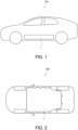
- FIG. 1 is a side perspective view showing a main part of an electric vehicle 100 on which a battery case 1 according to an embodiment of the present invention is mounted.
- FIG. 2 is a perspective plan view of the main part of the electric vehicle 100 viewed from a bottom side.
- the battery case 1 accommodates a battery used as a drive source of the electric vehicle 100 (hereinafter, referred to as a vehicle 100).
- the battery case 1 is disposed below a floor of the vehicle 100 over a region corresponding to the floor of the vehicle 100.
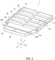
- FIG. 3 is a perspective view illustrating the battery case 1.
- arrows representing a vehicle front direction F and a vehicle rear direction R, an arrow representing a vehicle width direction W, and an arrow representing a vehicle upper-lower direction Z are described.
- the vehicle front-rear direction, the vehicle width direction, and the vehicle upper-lower direction may be referred to as a front-rear direction FR, a width direction W, and an upper-lower direction Z, respectively.
- the battery case 1 includes side frames 10, cross members 20, a front frame 30, a rear frame 40, and a bottom plate 50.
- a pair of side frames 10 are provided at a predetermined interval in the vehicle width direction W, and constitute left and right side walls of the battery case 1. Further, the side frame 10 extends along the front-rear direction FR of the vehicle 100.
- the front frame 30 constitutes a front side wall in the vehicle front-rear direction FR
- the rear frame 40 constitutes a rear side wall in the vehicle front-rear direction FR
- the bottom plate 50 constitutes a case bottom surface that functions as a battery placement surface in the battery case 1.
- the side frames 10, the front frame 30, and the rear frame 40 are provided upright with respect to a peripheral edge of the bottom plate 50, and are joined by welding, thereby constituting a box-shaped case. Further, an internal space formed by the side frames 10, the front frame 30, and the rear frame 40 is partitioned by a plurality of cross members 20.
- Each of the cross members 20 partitions the internal space of the battery case 1 in the front-rear direction FR, and extends from one side frame 10 to the other side frame 10.
- the battery case 1 includes four cross members 20.
- the battery is accommodated in each of a plurality of sections formed by the cross members 20 in the internal space of the battery case 1.
- a plurality of battery modules constitute one battery (battery pack).
- the battery case 1 is covered with a case cover (not shown) in a state in which the battery module formed by a lithium ion battery or the like is accommodated in the internal space.
- the battery case 1 in which the battery is accommodated includes side brackets 60 and rear side brackets 60R on an outer side in a vehicle body width direction of the side frame 10, and is attached to a vehicle body of the vehicle 100 by the side brackets 60 and the rear side brackets 60R.
- the battery case 1 is formed by maximally using a floor region of the vehicle 100. Therefore, in the width direction W of the vehicle 100, a space between the battery case 1 and the vehicle body of the vehicle 100 is reduced. Therefore, the battery case 1 is required to have sufficient durability against a load input to the vehicle 100 particularly due to a collision or the like from a side among an impact that may be input to the vehicle 100.
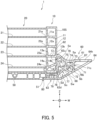
- FIG. 4 is a cross-sectional view taken along a line IV-IV in FIG. 3 .
- the side bracket 60 is fixed to an outer surface 10S of each of the side frames 10 that form the left and right walls of the internal space of the battery case 1 by welding or the like.
- the side frame 10 is a hollow plate-shaped member and includes a frame rib 11 extending in the width direction W inside the side frame 10.
- the side frame 10 includes four frame ribs, that is, frame ribs 11, 12, 13, and 14 that partition an inside of the side frame 10 in the upper-lower direction Z.
- Strength of the side frame 10 in the width direction W is increased by the frame ribs 11, 12, 13, and 14 extending in the width direction W inside the side frame 10.
- the side bracket 60 fixed to an outside of the side frame 10 will be described.
- the side bracket 60 includes a main body portion 61 that attaches the battery case 1 to the vehicle body, an abutting portion 62 that constitutes one surface of the main body portion 61 on a side frame 10 side and abuts against the outer surface 10S of the side frame 10, and a support portion 63 that protrudes from a lower end 62d of the abutting portion 62 and supports the battery case 1 from below.
- the abutting portion 62 is fixed to the outer surface 10S and the support portion 63 is fixed to the bottom plate 50 of the battery case 1 by welding or the like.
- the main body portion 61 includes a protruding end portion 64 that protrudes from the abutting portion 62 toward an outside of the vehicle in the width direction W of the battery case 1.
- a hole 64h that penetrates in the upper-lower direction Z is formed in the protruding end portion 64, and the side bracket 60 and the vehicle 100 are fixed by a bolt that pass through the hole 64h.
- the side bracket 60 is a hollow rod-shaped member, and includes a bracket rib 65 extending in the width direction W inside the side bracket 60. In this way, strength of the side bracket 60 in the width direction W is increased by the bracket rib 65 extending in the width direction W inside the side bracket 60.
- the rear side bracket 60R will be described in conjunction with a second embodiment of the side bracket 60.
- the cross member 20 is a hollow plate-shaped member and includes a member rib 21 extending in the width direction W inside the cross member 20.
- the cross member 20 includes four member ribs, that is, member ribs 21, 22, 23, and 24 that partition an interior of the cross member 20 in the upper-lower direction Z.
- strength of the cross member 20 in the width direction W is increased by the member ribs 21, 22, 23, and 24 extending in the width direction W inside the cross member 20.
- an end portion 65e of the bracket rib 65 on the side frame 10 side and an end portion 14b of the frame rib 14 on a side bracket 60 side are disposed in a manner of corresponding to each other in the upper-lower direction Z. That is, a height position in the upper-lower direction Z of the end portion 65e of the bracket rib 65 on the side frame 10 side is substantially the same as a height position in the upper-lower direction Z of the end portion 14b of the frame rib 14 on the side bracket 60 side.
- a load transmission path (hereinafter, referred to as a load path) for transmitting, from the bracket rib 65 to the frame rib 14, the load input to the side bracket 60 from the side of the vehicle 100, is formed.
- an end portion 11a of the frame rib 11 on a cross member 20 side and an end portion 21e of the member rib 21 on the side frame 10 side are disposed in a manner of corresponding to each other in the vehicle upper-lower direction Z. That is, a height position in the upper-lower direction Z of the end portion 11a of the frame rib 11 on the cross member 20 side is substantially the same as a height position in the upper-lower direction Z of the end portion 21e of the member rib 21 on the side frame 10 side.
- an end portion 12a of the frame rib 12 on the cross member 20 side and an end portion 22e of the member rib 22 on the side frame 10 side are disposed in a manner of corresponding to each other in the vehicle upper-lower direction Z. That is, a height position in the upper-lower direction Z of the end portion 12a of the frame rib 12 on the cross member 20 side is substantially the same as a height position in the upper-lower direction Z of the end portion 22e of the member rib 22 on the side frame 10 side.
- height positions in the upper-lower direction Z of an end portion 13a of the frame rib 13 and an end portion 14a of the frame rib 14 on the cross member 20 side are substantially the same as height positions in the upper-lower direction Z of an end portion 23e of the member rib 23 and an end portion 24e of the member rib 24 on the side frame 10 side, respectively.
- load paths for transmitting a load input to the frame ribs 11, 12, 13, and 14 of the side frame 10 to the member ribs 21, 22, 23, and 24 of the cross member 20 are formed.
- the side bracket 60 includes a main body upper surface portion 67 extending from the protruding end portion 64 to an upper end 62u of the abutting portion 62, and a main body lower surface portion 68 extending from the protruding end portion 64 to a lower end 62d of the abutting portion 62.
- a cross-sectional shape in the upper-lower direction Z along the width direction W is a shape that spreads in the upper-lower direction Z from the protruding end portion 64 toward a vehicle inner side in the width direction W and is continuous with the abutting portion 62.
- the side bracket 60 is disposed such that the upper end 62u of the abutting portion 62 and an end portion 13b of the frame rib 13 on the side bracket 60 side correspond to each other in the upper-lower direction Z. That is, a height position of the upper end 62u of the abutting portion 62 in the upper-lower direction Z and a height position of the frame rib 13 in the upper-lower direction Z are substantially the same.
- a load path is formed in which a load input from the protruding end portion 64 of the side bracket 60 is dispersed so as to spread in the upper-lower direction Z and transmitted to the side frame 10.
- the side bracket 60 has a passage 66 extending in the front-rear direction FR by partitioning an inside of the side bracket 60 by the bracket rib 65.
- the passage 66 is a refrigerant passage through which a refrigerant that cools an in-vehicle device such as a motor for a rear wheel provided in the vehicle 100 passes.
- a part of each of the pair of side frames 10 is curved such that a distance between the side frames 10 in the width direction W is gradually decreases along the front-rear direction FR so that the battery case 1 has a shape corresponding to a place where the battery case 1 can be mounted in the vehicle 100.
- a curved portion 10C is seamless, that is, formed seamlessly, by bending in a plurality of stages.
- the battery case 1 includes the pair of side frames 10 constituting the left and right side walls in the vehicle width direction W, the cross members 20 each extending from one side frame 10 to the other side frame 10, and the side brackets 60 each fixed to the outer surface 10S of the side frame 10 and attaching the battery case 1 to the vehicle body.
- the pair of side frames 10 constituting the left and right side walls in the vehicle width direction W are supported by the cross members 20 in the vehicle width direction W.
- the side frame 10 includes the frame ribs 11, 12, 13, and 14 extending in the vehicle width direction W in the side frame 10.
- the side frame 10 is supported in the vehicle width direction W by frame ribs 11, 12, 13, and 14 inside the side frame 10.
- the side bracket 60 includes the bracket rib 65 extending in the vehicle width direction W inside the side bracket 60.
- the side bracket 60 is supported by the bracket rib 65 in the vehicle width direction W inside the side bracket 60.
- the strength of the side frame 10 and the side bracket 60 in the vehicle width direction W is increased by the frame ribs 11, 12, 13, and 14 and the bracket rib 65, and the pair of side frames 10 are supported by the cross members 20 in the vehicle width direction W. Therefore, since the strength of the battery case 1 is increased when the load is applied in the vehicle width direction W, the durability against, for example, a collision from a side surface of the vehicle 100 can be improved.
- the battery case 1 is disposed such that the end portion 65e of the bracket rib 65 on the side frame 10 side and the end portion 14b of the frame rib 14 on the side bracket 60 side correspond to each other in the vehicle upper-lower direction Z. Accordingly, the load path is formed from the bracket rib 65 to the frame rib 14. Therefore, the load input to the side bracket 60 from an outer side in the vehicle width direction W can be more reliably dispersed from the side bracket 60 to the side frame 10.
- a height position of the frame rib 14 in the vehicle upper-lower direction Z and a height position of the bracket rib 65 are aligned, so that rigidity of the battery case 1 in the vehicle width direction W is increased, and the load input from the side of the vehicle 100 can be smoothly transmitted in the vehicle width direction W of the battery case 1.
- the cross member 20 includes the member ribs 21, 22, 23, and 24 extending in the vehicle width direction W in the cross member 20. Accordingly, since the cross member 20 is supported in the vehicle width direction W by the member ribs 21, 22, 23, 24 inside the cross member 20, the strength of the cross member 20 in the vehicle width direction W can be improved.
- the height positions of the end portions 11a, 12a, 13a, and 14a of the frame ribs 11, 12, 13, and 14 on the cross member 20 side in the vehicle upper-lower direction Z are aligned with the height positions of the end portions 21e, 22e, 23e, and 24e of the member ribs 21, 22, 23, and 24 on the side frame 10 side, respectively.
- the load paths are formed from the frame ribs 11, 12, 13, and 14 to the member ribs 21, 22, 23, and 24. Accordingly, the load input to the side bracket 60 from the outer side in the vehicle width direction W can be more reliably dispersed from the side frame 10 to the cross member 20.
- the height position of the frame rib 14 and the height position of the bracket rib 65 in the vehicle upper-lower direction Z are aligned, and the height positions of the end portions 11a, 12a, 13a, 14a of the frame ribs 11, 12, 13, 14 on the cross member 20 side and the height positions of the end portions 21e, 22e, 23e, 24e of the member ribs 21, 22, 23, 24 on the side frame 10 side are aligned, respectively, and thus the rigidity of the battery case 1 in the vehicle width direction W is increased, and the load input from the side of the vehicle 100 can be smoothly transmitted in the vehicle width direction W of the battery case 1.
- the side bracket 60 includes the abutting portion 62 that abuts against the outer surface 10S of the side frame 10 and the support portion 63 that supports a bottom portion of the battery case 1 from below. That is, the battery case 1 is supported by the vehicle body in a manner of being embraced by the side bracket 60. Therefore, even when an excessive load is input to the side surface of the vehicle 100, it is possible to prevent joining between the side bracket 60 and the battery case 1 from being broken and the battery case 1 from falling off from the vehicle body.
- the upper end 62u of the abutting portion 62 and the end portion 13b of the frame rib 13 on the side bracket 60 side are disposed in a manner of corresponding to each other in the vehicle upper-lower direction Z. Therefore, the load path is formed from the abutting portion 62 of the side bracket 60 through the frame rib 13. Accordingly, the load input from the side bracket 60 can be more reliably dispersed to the side frame 10.
- the side bracket 60 has the passage 66 extending in the vehicle front-rear direction FR by partitioning the inside of the side bracket 60 by the bracket rib 65.
- the passage 66 is a refrigerant passage for cooling the in-vehicle device. Therefore, it is not necessary to separately form the refrigerant passage, and a layout of the vehicle 100 can be improved. Since the refrigerant passage can be formed inside the side bracket 60, the passage 66 as the refrigerant passage can be protected from the load from the outside.
- each of the pair of side frames 10 includes the curved portion 10C that is curved such that the distance between the pair of side frames 10 in the width direction W gradually decreases along the front-rear direction FR.
- the curved portion 10C is formed by seamless processing and includes no welded portion. Therefore, the rigidity of the side frame 10 can be increased compared to a case in which the side frame 10 is formed by a combination of linear members.
- the durability against the load input to the side surface of the vehicle 100 can be improved, and the accommodated battery can be more reliably protected.
- FIG. 5 is a cross-sectional view illustrating the battery case 1 according to a second embodiment of the present invention by cutting out the battery case 1 at the same position as the battery case 1 according to the first embodiment shown in FIG. 3 .
- the battery case 1 shown as the second embodiment is different from the battery case 1 shown as the first embodiment in the structure of the side bracket 60.
- components having the same functions as those described in the battery case 1 are denoted by the same reference signs, and detailed description thereof will be omitted.
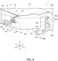
- FIG. 6 is a perspective view of a main part of the battery case 1 in FIG. 5 as viewed from a bottom side of the vehicle 100. As shown in FIG. 6 , a step portion 51 is formed on a lower surface of the bottom plate 50 constituting a bottom portion of the battery case 1 along the front-rear direction FR of the vehicle 100.
- a lower end surface of the support portion 63 is formed in a manner of protruding to one side, and the support portion 63 includes a facing portion 80 facing the step portion 51 located on a vehicle outer side in the width direction W.
- a flat structure is formed in which the step portion 51 and the facing portion 80 are disposed in a manner of butting each other, and the lower surface of the support portion 63 of the main body portion 61 and the lower surface of the bottom plate 50 forming the bottom portion of the battery case 1 are flat in the vehicle upper-lower direction Z.
- the side bracket 60 includes a first rib 71, a second rib 72, a third rib 73, a fourth rib 74, a fifth rib 75, a sixth rib 76, and a seventh rib 77 extending in the width direction W or the upper-lower direction Z inside the side bracket 60.
- first rib 71 is connected to the main body upper surface portion 67, extends along the upper-lower direction Z, and the other end thereof is connected to the main body lower surface portion 68. Further, the first rib 71 extends in the front-rear direction FR.
- One end of the second rib 72 is connected to the vicinity of a central portion 71c of the first rib 71 in the upper-lower direction Z and extends in the width direction W and the front-rear direction FR.
- One end of the third rib 73 is connected to an inner side in the width direction W with respect to a connection portion between the main body lower surface portion 68 and the first rib 71, and extends in the width direction W and the front-rear direction FR.
- One end of the fourth rib 74 is connected to an inner side in the width direction W with respect to a connection portion between the main body upper surface portion 67 and the first rib 71, and extends in the upper-lower direction Z and the front-rear direction FR.
- the other end of the second rib 72, the other end of the third rib 73, and the other end of the fourth rib 74 are aggregated and connected in the vicinity of a center inside the side bracket 60, and form a first aggregated portion 78.
- One end of the fifth rib 75 is connected to the main body upper surface portion 67 and extends in the width direction W and the front-rear direction FR.
- One end of the sixth rib 76 is connected to the first aggregated portion 78 and extends in the width direction W and the front-rear direction FR.
- the other end of the fifth rib 75 and the other end of the sixth rib 76 are aggregated and connected in the abutting portion 62 to form a second aggregated portion 79.
- the seventh rib 77 extends from the first aggregated portion 78 in a direction different from the sixth rib 76 in the width direction W and is connected to the abutting portion 62.
- a first load path is formed through which a load input from the protruding end portion 64 is transmitted to the side frame 10 through the main body upper surface portion 67, the first rib 71, the second rib 72, and the seventh rib 77.
- a second load path is formed through which the load input from the protruding end portion 64 is transmitted to the side frame 10 through the main body lower surface portion 68, the third rib 73, the first aggregated portion 78, the sixth rib 76, and the second aggregated portion 79.
- a second load path is formed through which the load input from the protruding end portion 64 is transmitted to the side frame 10 through the main body upper surface portion 67, the fourth rib 74, the first aggregated portion 78, and the sixth rib 76.
- a third load path is formed through which the load input from the protruding end portion 64 is transmitted to the side frame 10 from the main body upper surface portion 67, the fifth rib 75, and the second aggregated portion 79.
- a fourth load path is formed through which the load input from the protruding end portion 64 is transmitted to the bottom plate 50 through the main body upper surface portion 67, the fourth rib 74, the first aggregated portion 78, the seventh rib 77, and the support portion 63.
- the fourth rib 74, the fifth rib 75, and the sixth rib 56 are formed such that a cross-sectional shape in the upper-lower direction Z along the width direction W is circular. That is, a cylindrical passage Sw extending in the front-rear direction FR is formed by the fourth rib 74, the fifth rib 75, and the sixth rib 56 in the side bracket 60.
- the cylindrical passage Sw is a passage for conveying a refrigerant that cools an in-vehicle device provided in the vehicle 100.
- the side bracket 60 includes the first rib 71 to the seventh rib 77 described above, an inside of the side bracket 60 is partitioned into the cylindrical passage Sw and spaces Sa, Sb, Sc, Sd, Se in a cross section in the upper-lower direction Z along the width direction W.
- the spaces Sa, Sb, Sc, Sd, and Se are crushed by deformation or breakage of the first rib 71 to the fifth rib 75. That is, the spaces Sa, Sb, Sc, Sd, and Se function as a buffer structure that absorbs the load transmitted to the side frame 10.
- the rear side bracket 60R includes a main body portion 61R that attaching the battery case 1 to the vehicle body, an abutting portion 62R that constitutes one surface of the main body portion 61R on a side frame 10 side and abuts against the outer surface 10S of the side frame 10, and a support portion 63R that protrudes from a lower end of the abutting portion 62R and supports the battery case 1 from a lower side.
- a first rib 71R, a second rib 72R, and a third rib 73R are provided inside the rear side bracket 60R.
- the first rib 71R extends in the front-rear direction FR along the upper-lower direction Z. Further, the second rib 72R and the third rib 73R are disposed in a manner of partitioning an inside of the rear side bracket 60R in the upper-lower direction Z.
- the rear side bracket 60R is also disposed such that end portions 72Re and 73Re respectively provided in the second rib 72R and the third rib 73R, which extend in the width direction W, on the side frame 10 side correspond to end portions of the frame ribs 11, 12, 13, and 14 provided inside the side frame 10 on a rear side bracket 60R side.
- a load path is formed through which a load input to the rear side bracket 60R is transmitted to the side frame 10.
- the rear side bracket 60R includes the second rib 72R and the third rib 73R extending in the vehicle width direction W inside the rear side bracket 60R. Accordingly, the rear side bracket 60R is supported in the vehicle width direction W by the second rib 72R and the third rib 73R inside the rear side bracket 60R. Therefore, strength of the rear side bracket 60R in the vehicle width direction W is increased.
- the second rib 72R and the third rib 73R of the rear side bracket 60R are disposed such that height positions of the end portions 72Re and 73Re thereof on the side frame 10 side are aligned with height positions of the end portions of the frame ribs 11, 12, 13, and 14, which are disposed inside the side frame 10, on the rear side bracket 60R side.
- the load path passes from the second rib 72R and the third rib 73R of the rear side bracket 60R to the frame ribs 11, 12, 13, and 14 is formed. Therefore, the load input to the rear side bracket 60R from the outer side in the vehicle width direction W can be more reliably dispersed to the side frame 10.
- the height positions of the end portion 72Re of the second rib 72R and the end portion 73Re of the third rib 73R of the rear side bracket 60R on the side frame 10 side are aligned with the height positions of the end portions of the frame ribs 11, 12, 13, and 14, which are disposed inside the side frame 10, on the rear side bracket 60R side, and thus even on the rear side of the vehicle 100, rigidity of the battery case 1 in the vehicle width direction W is increased, and the load input from a side of the vehicle 100 can be smoothly transmitted in the vehicle width direction W of the battery case 1.
- the first rib 71, the second rib 72, the third rib 73, the fourth rib 74, the fifth rib 75, the sixth rib 76, and the seventh rib 77 extending in the width direction W or the upper-lower direction Z are formed inside the side bracket 60. This further increases the strength of the side bracket 60 in the vehicle width direction W and the upper-lower direction Z.
- a load path such as the first load path to the fourth load path is formed in the side bracket 60 as an example. Therefore, the load input from the protruding end portion 64 of the side bracket 60 can be more reliably dispersed to the side frame 10.
- a height position of the second aggregated portion 79 in the side bracket 60 is aligned with a height position of the end portion 14b on the side bracket 60 side of the frame rib 14 in the side frame 10.
- the load path formed in this manner can smoothly transmit the load input from the side of the vehicle 100 in the vehicle width direction W of the battery case 1.
- the spaces Sa, Sb, Sc, Sd, and Se that function as the buffer structure are formed inside the side bracket 60 by the first rib 71 to the seventh rib 77 provided therein.
- the spaces Sa, Sb, Sc, Sd, and Se are crushed, so that the excessive load input from the side of the vehicle 100 can be absorbed. Therefore, it is possible to prevent the excessive load from being transmitted to the side frame 10.
- the cylindrical passage Sw having a cylindrical shape is formed inside the side bracket 60.
- the passage has such a cylindrical shape, a stress is unlikely to concentrate, and strength of the passage is increased. Furthermore, it also contributes to strength improvement of the side bracket 60 as a whole.
- the durability against the load input to the side surface of the vehicle 100 can be improved, and an accommodated battery can be more reliably protected.
- the curved portion 10C formed in the side frame 10 is not limited to one position. A position thereof can be appropriately changed according to a design of the battery case 1. Curved portions may be formed at a plurality of positions of the side frame 10.
- the cross-sectional shapes of the side frame 10 and the cross member 20 are not limited to the shapes shown in FIGS. 4 and 6 .
- a position of the cylindrical passage Sw in the side bracket 60 is not limited to the position shown in FIG. 6 . Further, any one of the spaces Sa, Sb, Sc, Sd, and Se formed by partitioning the inside of the side bracket 60 by the first rib 71 - the seventh rib 77 may be used as the refrigerant passage.
- the load paths formed in the side bracket 60 by providing the first rib 71 to the seventh rib 77 is not limited to the first load path to the fourth load path described above.
Landscapes
- Engineering & Computer Science (AREA)
- Chemical & Material Sciences (AREA)
- Transportation (AREA)
- Mechanical Engineering (AREA)
- Chemical Kinetics & Catalysis (AREA)
- Electrochemistry (AREA)
- General Chemical & Material Sciences (AREA)
- Combustion & Propulsion (AREA)
- Sustainable Energy (AREA)
- Power Engineering (AREA)
- Sustainable Development (AREA)
- Life Sciences & Earth Sciences (AREA)
- Aviation & Aerospace Engineering (AREA)
- Arrangement Or Mounting Of Propulsion Units For Vehicles (AREA)
- Secondary Cells (AREA)
- Battery Mounting, Suspending (AREA)
- Body Structure For Vehicles (AREA)
Abstract
Description
- The present invention relates to a battery case.
-
JP 2936959 B - In
JP 2936959 B - Since the electric vehicle described in
JP 2936959 B - An object of the present invention is to provide a technique for improving durability against a load input to a side surface of an electric vehicle.
- According to one aspect of the present invention, a battery case that accommodates a battery for an electric vehicle is provided.
- The battery case includes a pair of side frames, a cross member, and a side bracket. The pair of side frames constitute left and right side walls of the battery case in a vehicle width direction and extend along a vehicle front-rear direction. The cross member partitions an internal space of the battery case in the vehicle front-rear direction and extends from one of the side frames to the other side frame. The side bracket is fixed to an outer surface of the side frame and is configured to attach the battery case to a vehicle body. The side frame includes a frame rib extending in the vehicle width direction inside the side frame and the side bracket includes a bracket rib extending in the vehicle width direction inside the side bracket.
-
- [
FIG. 1] FIG. 1 is a side perspective view showing a main part of an electric vehicle on which a battery case according to an embodiment of the present invention is mounted. - [
FIG. 2] FIG. 2 is a perspective plan view of the main part of the electric vehicle on which the battery case according to the embodiment of the present invention is mounted, as viewed from a bottom side. - [
FIG. 3] FIG. 3 is a perspective view illustrating the battery case according to a first embodiment of the present invention. - [
FIG. 4] FIG. 4 is a cross-sectional view taken along a line IV-IV inFIG. 3 . - [
FIG. 5] FIG. 5 is a cross-sectional view illustrating a battery case according to a second embodiment of the present invention by cutting out the battery case at the same position as the battery case according to the first embodiment shown inFIG. 3 . - [
FIG. 6] FIG. 6 is a perspective view of a main part of the battery case inFIG. 5 as viewed from a bottom side of a vehicle. - Hereinafter, embodiments according to the present invention will be described with reference to the drawings.
-
FIG. 1 is a side perspective view showing a main part of anelectric vehicle 100 on which abattery case 1 according to an embodiment of the present invention is mounted.FIG. 2 is a perspective plan view of the main part of theelectric vehicle 100 viewed from a bottom side. - As shown in
FIGS. 1 and 2 , thebattery case 1 accommodates a battery used as a drive source of the electric vehicle 100 (hereinafter, referred to as a vehicle 100). Thebattery case 1 is disposed below a floor of thevehicle 100 over a region corresponding to the floor of thevehicle 100. -
FIG. 3 is a perspective view illustrating thebattery case 1. InFIG. 3 , arrows representing a vehicle front direction F and a vehicle rear direction R, an arrow representing a vehicle width direction W, and an arrow representing a vehicle upper-lower direction Z are described. The vehicle front-rear direction, the vehicle width direction, and the vehicle upper-lower direction may be referred to as a front-rear direction FR, a width direction W, and an upper-lower direction Z, respectively. - As shown in
FIG. 3 , thebattery case 1 includesside frames 10,cross members 20, afront frame 30, arear frame 40, and abottom plate 50. - A pair of
side frames 10 are provided at a predetermined interval in the vehicle width direction W, and constitute left and right side walls of thebattery case 1. Further, theside frame 10 extends along the front-rear direction FR of thevehicle 100. - The
front frame 30 constitutes a front side wall in the vehicle front-rear direction FR, and therear frame 40 constitutes a rear side wall in the vehicle front-rear direction FR. Further, thebottom plate 50 constitutes a case bottom surface that functions as a battery placement surface in thebattery case 1. - The
side frames 10, thefront frame 30, and therear frame 40 are provided upright with respect to a peripheral edge of thebottom plate 50, and are joined by welding, thereby constituting a box-shaped case. Further, an internal space formed by theside frames 10, thefront frame 30, and therear frame 40 is partitioned by a plurality ofcross members 20. - Each of the
cross members 20 partitions the internal space of thebattery case 1 in the front-rear direction FR, and extends from oneside frame 10 to theother side frame 10. In the first embodiment, thebattery case 1 includes fourcross members 20. - Although not shown in
FIG. 3 , the battery is accommodated in each of a plurality of sections formed by thecross members 20 in the internal space of thebattery case 1. A plurality of battery modules constitute one battery (battery pack). Thebattery case 1 is covered with a case cover (not shown) in a state in which the battery module formed by a lithium ion battery or the like is accommodated in the internal space. - As described above, the
battery case 1 in which the battery is accommodated includesside brackets 60 andrear side brackets 60R on an outer side in a vehicle body width direction of theside frame 10, and is attached to a vehicle body of thevehicle 100 by theside brackets 60 and therear side brackets 60R. - From the viewpoint of increasing a load of the battery as the drive source, as shown in
FIG. 2 , thebattery case 1 is formed by maximally using a floor region of thevehicle 100. Therefore, in the width direction W of thevehicle 100, a space between thebattery case 1 and the vehicle body of thevehicle 100 is reduced. Therefore, thebattery case 1 is required to have sufficient durability against a load input to thevehicle 100 particularly due to a collision or the like from a side among an impact that may be input to thevehicle 100. -
FIG. 4 is a cross-sectional view taken along a line IV-IV inFIG. 3 . As shown inFIG. 4 , theside bracket 60 is fixed to anouter surface 10S of each of theside frames 10 that form the left and right walls of the internal space of thebattery case 1 by welding or the like. - The
side frame 10 is a hollow plate-shaped member and includes aframe rib 11 extending in the width direction W inside theside frame 10. In the present embodiment, theside frame 10 includes four frame ribs, that is,frame ribs side frame 10 in the upper-lower direction Z. - Strength of the
side frame 10 in the width direction W is increased by theframe ribs side frame 10. - Next, the
side bracket 60 fixed to an outside of theside frame 10 will be described. Theside bracket 60 includes amain body portion 61 that attaches thebattery case 1 to the vehicle body, anabutting portion 62 that constitutes one surface of themain body portion 61 on aside frame 10 side and abuts against theouter surface 10S of theside frame 10, and asupport portion 63 that protrudes from alower end 62d of the abuttingportion 62 and supports thebattery case 1 from below. The abuttingportion 62 is fixed to theouter surface 10S and thesupport portion 63 is fixed to thebottom plate 50 of thebattery case 1 by welding or the like. - The
main body portion 61 includes aprotruding end portion 64 that protrudes from theabutting portion 62 toward an outside of the vehicle in the width direction W of thebattery case 1. Ahole 64h that penetrates in the upper-lower direction Z is formed in the protrudingend portion 64, and theside bracket 60 and thevehicle 100 are fixed by a bolt that pass through thehole 64h. - The
side bracket 60 is a hollow rod-shaped member, and includes abracket rib 65 extending in the width direction W inside theside bracket 60. In this way, strength of theside bracket 60 in the width direction W is increased by thebracket rib 65 extending in the width direction W inside theside bracket 60. - The
rear side bracket 60R will be described in conjunction with a second embodiment of theside bracket 60. - Next, the
cross member 20 disposed between the pair ofside frames 10 will be described. Thecross member 20 is a hollow plate-shaped member and includes amember rib 21 extending in the width direction W inside thecross member 20. In the present embodiment, thecross member 20 includes four member ribs, that is,member ribs cross member 20 in the upper-lower direction Z. Thus, strength of thecross member 20 in the width direction W is increased by themember ribs cross member 20. - In the present embodiment, as shown in
FIG. 4 , anend portion 65e of thebracket rib 65 on theside frame 10 side and anend portion 14b of theframe rib 14 on aside bracket 60 side are disposed in a manner of corresponding to each other in the upper-lower direction Z. That is, a height position in the upper-lower direction Z of theend portion 65e of thebracket rib 65 on theside frame 10 side is substantially the same as a height position in the upper-lower direction Z of theend portion 14b of theframe rib 14 on theside bracket 60 side. - Accordingly, the strength of the
side frame 10 and theside bracket 60 in the width direction W is increased, and a load transmission path (hereinafter, referred to as a load path) for transmitting, from thebracket rib 65 to theframe rib 14, the load input to theside bracket 60 from the side of thevehicle 100, is formed. - As shown in
FIG. 4 , anend portion 11a of theframe rib 11 on across member 20 side and anend portion 21e of themember rib 21 on theside frame 10 side are disposed in a manner of corresponding to each other in the vehicle upper-lower direction Z. That is, a height position in the upper-lower direction Z of theend portion 11a of theframe rib 11 on thecross member 20 side is substantially the same as a height position in the upper-lower direction Z of theend portion 21e of themember rib 21 on theside frame 10 side. - Further, an
end portion 12a of theframe rib 12 on thecross member 20 side and anend portion 22e of themember rib 22 on theside frame 10 side are disposed in a manner of corresponding to each other in the vehicle upper-lower direction Z. That is, a height position in the upper-lower direction Z of theend portion 12a of theframe rib 12 on thecross member 20 side is substantially the same as a height position in the upper-lower direction Z of theend portion 22e of themember rib 22 on theside frame 10 side. - Similarly, height positions in the upper-lower direction Z of an
end portion 13a of theframe rib 13 and anend portion 14a of theframe rib 14 on thecross member 20 side are substantially the same as height positions in the upper-lower direction Z of anend portion 23e of themember rib 23 and anend portion 24e of themember rib 24 on theside frame 10 side, respectively. - Therefore, load paths for transmitting a load input to the
frame ribs side frame 10 to themember ribs cross member 20 are formed. - As shown in
FIG. 4 , theside bracket 60 includes a main bodyupper surface portion 67 extending from theprotruding end portion 64 to anupper end 62u of the abuttingportion 62, and a main bodylower surface portion 68 extending from theprotruding end portion 64 to alower end 62d of the abuttingportion 62. A cross-sectional shape in the upper-lower direction Z along the width direction W is a shape that spreads in the upper-lower direction Z from theprotruding end portion 64 toward a vehicle inner side in the width direction W and is continuous with the abuttingportion 62. - Further, the
side bracket 60 is disposed such that theupper end 62u of the abuttingportion 62 and anend portion 13b of theframe rib 13 on theside bracket 60 side correspond to each other in the upper-lower direction Z. That is, a height position of theupper end 62u of the abuttingportion 62 in the upper-lower direction Z and a height position of theframe rib 13 in the upper-lower direction Z are substantially the same. - Accordingly, a load path is formed in which a load input from the
protruding end portion 64 of theside bracket 60 is dispersed so as to spread in the upper-lower direction Z and transmitted to theside frame 10. - The
side bracket 60 has apassage 66 extending in the front-rear direction FR by partitioning an inside of theside bracket 60 by thebracket rib 65. In the present embodiment, thepassage 66 is a refrigerant passage through which a refrigerant that cools an in-vehicle device such as a motor for a rear wheel provided in thevehicle 100 passes. - As shown in
FIG. 3 , a part of each of the pair of side frames 10 is curved such that a distance between the side frames 10 in the width direction W is gradually decreases along the front-rear direction FR so that thebattery case 1 has a shape corresponding to a place where thebattery case 1 can be mounted in thevehicle 100. Acurved portion 10C is seamless, that is, formed seamlessly, by bending in a plurality of stages. - The
battery case 1 according to the first embodiment includes the pair of side frames 10 constituting the left and right side walls in the vehicle width direction W, thecross members 20 each extending from oneside frame 10 to theother side frame 10, and theside brackets 60 each fixed to theouter surface 10S of theside frame 10 and attaching thebattery case 1 to the vehicle body. In thebattery case 1, the pair of side frames 10 constituting the left and right side walls in the vehicle width direction W are supported by thecross members 20 in the vehicle width direction W. Theside frame 10 includes theframe ribs side frame 10. Theside frame 10 is supported in the vehicle width direction W byframe ribs side frame 10. Theside bracket 60 includes thebracket rib 65 extending in the vehicle width direction W inside theside bracket 60. Theside bracket 60 is supported by thebracket rib 65 in the vehicle width direction W inside theside bracket 60. - Thus, the strength of the
side frame 10 and theside bracket 60 in the vehicle width direction W is increased by theframe ribs bracket rib 65, and the pair of side frames 10 are supported by thecross members 20 in the vehicle width direction W. Therefore, since the strength of thebattery case 1 is increased when the load is applied in the vehicle width direction W, the durability against, for example, a collision from a side surface of thevehicle 100 can be improved. - The
battery case 1 is disposed such that theend portion 65e of thebracket rib 65 on theside frame 10 side and theend portion 14b of theframe rib 14 on theside bracket 60 side correspond to each other in the vehicle upper-lower direction Z. Accordingly, the load path is formed from thebracket rib 65 to theframe rib 14. Therefore, the load input to theside bracket 60 from an outer side in the vehicle width direction W can be more reliably dispersed from theside bracket 60 to theside frame 10. - Further, in the
side frame 10 and theside bracket 60, a height position of theframe rib 14 in the vehicle upper-lower direction Z and a height position of thebracket rib 65 are aligned, so that rigidity of thebattery case 1 in the vehicle width direction W is increased, and the load input from the side of thevehicle 100 can be smoothly transmitted in the vehicle width direction W of thebattery case 1. - In the
battery case 1, thecross member 20 includes themember ribs cross member 20. Accordingly, since thecross member 20 is supported in the vehicle width direction W by themember ribs cross member 20, the strength of thecross member 20 in the vehicle width direction W can be improved. - In the
battery case 1, the height positions of theend portions frame ribs cross member 20 side in the vehicle upper-lower direction Z are aligned with the height positions of theend portions member ribs side frame 10 side, respectively. - Therefore, in the
battery case 1, the load paths are formed from theframe ribs member ribs side bracket 60 from the outer side in the vehicle width direction W can be more reliably dispersed from theside frame 10 to thecross member 20. - Further, in the
side frame 10 and theside bracket 60, the height position of theframe rib 14 and the height position of thebracket rib 65 in the vehicle upper-lower direction Z are aligned, and the height positions of theend portions frame ribs cross member 20 side and the height positions of theend portions member ribs side frame 10 side are aligned, respectively, and thus the rigidity of thebattery case 1 in the vehicle width direction W is increased, and the load input from the side of thevehicle 100 can be smoothly transmitted in the vehicle width direction W of thebattery case 1. - In the
battery case 1, theside bracket 60 includes the abuttingportion 62 that abuts against theouter surface 10S of theside frame 10 and thesupport portion 63 that supports a bottom portion of thebattery case 1 from below. That is, thebattery case 1 is supported by the vehicle body in a manner of being embraced by theside bracket 60. Therefore, even when an excessive load is input to the side surface of thevehicle 100, it is possible to prevent joining between theside bracket 60 and thebattery case 1 from being broken and thebattery case 1 from falling off from the vehicle body. - In the
battery case 1, theupper end 62u of the abuttingportion 62 and theend portion 13b of theframe rib 13 on theside bracket 60 side are disposed in a manner of corresponding to each other in the vehicle upper-lower direction Z. Therefore, the load path is formed from the abuttingportion 62 of theside bracket 60 through theframe rib 13. Accordingly, the load input from theside bracket 60 can be more reliably dispersed to theside frame 10. - In the
battery case 1, theside bracket 60 has thepassage 66 extending in the vehicle front-rear direction FR by partitioning the inside of theside bracket 60 by thebracket rib 65. Thepassage 66 is a refrigerant passage for cooling the in-vehicle device. Therefore, it is not necessary to separately form the refrigerant passage, and a layout of thevehicle 100 can be improved. Since the refrigerant passage can be formed inside theside bracket 60, thepassage 66 as the refrigerant passage can be protected from the load from the outside. - In the
battery case 1, each of the pair of side frames 10 includes thecurved portion 10C that is curved such that the distance between the pair of side frames 10 in the width direction W gradually decreases along the front-rear direction FR. Thecurved portion 10C is formed by seamless processing and includes no welded portion. Therefore, the rigidity of theside frame 10 can be increased compared to a case in which theside frame 10 is formed by a combination of linear members. - As described above, according to the
battery case 1 described above, the durability against the load input to the side surface of thevehicle 100 can be improved, and the accommodated battery can be more reliably protected. -
FIG. 5 is a cross-sectional view illustrating thebattery case 1 according to a second embodiment of the present invention by cutting out thebattery case 1 at the same position as thebattery case 1 according to the first embodiment shown inFIG. 3 . - The
battery case 1 shown as the second embodiment is different from thebattery case 1 shown as the first embodiment in the structure of theside bracket 60. In thebattery case 1, components having the same functions as those described in thebattery case 1 are denoted by the same reference signs, and detailed description thereof will be omitted. -
FIG. 6 is a perspective view of a main part of thebattery case 1 inFIG. 5 as viewed from a bottom side of thevehicle 100. As shown inFIG. 6 , astep portion 51 is formed on a lower surface of thebottom plate 50 constituting a bottom portion of thebattery case 1 along the front-rear direction FR of thevehicle 100. - A lower end surface of the
support portion 63 is formed in a manner of protruding to one side, and thesupport portion 63 includes a facingportion 80 facing thestep portion 51 located on a vehicle outer side in the width direction W. - In the
battery case 1 according to the second embodiment, a flat structure is formed in which thestep portion 51 and the facingportion 80 are disposed in a manner of butting each other, and the lower surface of thesupport portion 63 of themain body portion 61 and the lower surface of thebottom plate 50 forming the bottom portion of thebattery case 1 are flat in the vehicle upper-lower direction Z. - Therefore, in the
battery case 1, when an excessive load is input, a load path is formed that connects the facingportion 80 of theside bracket 60 to thestep portion 51 of thebottom plate 50. - In the second embodiment, the
side bracket 60 includes afirst rib 71, asecond rib 72, athird rib 73, a fourth rib 74, a fifth rib 75, asixth rib 76, and aseventh rib 77 extending in the width direction W or the upper-lower direction Z inside theside bracket 60. - One end of the
first rib 71 is connected to the main bodyupper surface portion 67, extends along the upper-lower direction Z, and the other end thereof is connected to the main bodylower surface portion 68. Further, thefirst rib 71 extends in the front-rear direction FR. One end of thesecond rib 72 is connected to the vicinity of acentral portion 71c of thefirst rib 71 in the upper-lower direction Z and extends in the width direction W and the front-rear direction FR. One end of thethird rib 73 is connected to an inner side in the width direction W with respect to a connection portion between the main bodylower surface portion 68 and thefirst rib 71, and extends in the width direction W and the front-rear direction FR. One end of the fourth rib 74 is connected to an inner side in the width direction W with respect to a connection portion between the main bodyupper surface portion 67 and thefirst rib 71, and extends in the upper-lower direction Z and the front-rear direction FR. The other end of thesecond rib 72, the other end of thethird rib 73, and the other end of the fourth rib 74 are aggregated and connected in the vicinity of a center inside theside bracket 60, and form a first aggregatedportion 78. - One end of the fifth rib 75 is connected to the main body
upper surface portion 67 and extends in the width direction W and the front-rear direction FR. One end of thesixth rib 76 is connected to the first aggregatedportion 78 and extends in the width direction W and the front-rear direction FR. The other end of the fifth rib 75 and the other end of thesixth rib 76 are aggregated and connected in the abuttingportion 62 to form a second aggregatedportion 79. Theseventh rib 77 extends from the first aggregatedportion 78 in a direction different from thesixth rib 76 in the width direction W and is connected to the abuttingportion 62. - In the second embodiment, by providing these ribs, strength of the
side bracket 60 in the vehicle width direction W and the upper-lower direction Z is increased. - In the second embodiment, the following load paths are formed in the
side bracket 60 as examples. That is, a first load path is formed through which a load input from theprotruding end portion 64 is transmitted to theside frame 10 through the main bodyupper surface portion 67, thefirst rib 71, thesecond rib 72, and theseventh rib 77. Further, a second load path is formed through which the load input from theprotruding end portion 64 is transmitted to theside frame 10 through the main bodylower surface portion 68, thethird rib 73, the first aggregatedportion 78, thesixth rib 76, and the second aggregatedportion 79. Further, a second load path is formed through which the load input from theprotruding end portion 64 is transmitted to theside frame 10 through the main bodyupper surface portion 67, the fourth rib 74, the first aggregatedportion 78, and thesixth rib 76. Further, a third load path is formed through which the load input from theprotruding end portion 64 is transmitted to theside frame 10 from the main bodyupper surface portion 67, the fifth rib 75, and the second aggregatedportion 79. Furthermore, a fourth load path is formed through which the load input from theprotruding end portion 64 is transmitted to thebottom plate 50 through the main bodyupper surface portion 67, the fourth rib 74, the first aggregatedportion 78, theseventh rib 77, and thesupport portion 63. - The fourth rib 74, the fifth rib 75, and the sixth rib 56 are formed such that a cross-sectional shape in the upper-lower direction Z along the width direction W is circular. That is, a cylindrical passage Sw extending in the front-rear direction FR is formed by the fourth rib 74, the fifth rib 75, and the sixth rib 56 in the
side bracket 60. The cylindrical passage Sw is a passage for conveying a refrigerant that cools an in-vehicle device provided in thevehicle 100. - Since the
side bracket 60 includes thefirst rib 71 to theseventh rib 77 described above, an inside of theside bracket 60 is partitioned into the cylindrical passage Sw and spaces Sa, Sb, Sc, Sd, Se in a cross section in the upper-lower direction Z along the width direction W. - When the excessive load is input to the
side bracket 60, the spaces Sa, Sb, Sc, Sd, and Se are crushed by deformation or breakage of thefirst rib 71 to the fifth rib 75. That is, the spaces Sa, Sb, Sc, Sd, and Se function as a buffer structure that absorbs the load transmitted to theside frame 10. - Next, the
rear side bracket 60R will be described. - The
rear side bracket 60R includes amain body portion 61R that attaching thebattery case 1 to the vehicle body, an abuttingportion 62R that constitutes one surface of themain body portion 61R on aside frame 10 side and abuts against theouter surface 10S of theside frame 10, and asupport portion 63R that protrudes from a lower end of the abuttingportion 62R and supports thebattery case 1 from a lower side. - A
first rib 71R, asecond rib 72R, and athird rib 73R are provided inside therear side bracket 60R. - The
first rib 71R extends in the front-rear direction FR along the upper-lower direction Z. Further, thesecond rib 72R and thethird rib 73R are disposed in a manner of partitioning an inside of therear side bracket 60R in the upper-lower direction Z. - Although not shown in
FIG. 6 , therear side bracket 60R is also disposed such that end portions 72Re and 73Re respectively provided in thesecond rib 72R and thethird rib 73R, which extend in the width direction W, on theside frame 10 side correspond to end portions of theframe ribs side frame 10 on arear side bracket 60R side. - Accordingly, similarly to the
side bracket 60, a load path is formed through which a load input to therear side bracket 60R is transmitted to theside frame 10. - First, effects of the
rear side bracket 60R which is also provided in thebattery case 1 according to the first embodiment will be described. Therear side bracket 60R includes thesecond rib 72R and thethird rib 73R extending in the vehicle width direction W inside therear side bracket 60R. Accordingly, therear side bracket 60R is supported in the vehicle width direction W by thesecond rib 72R and thethird rib 73R inside therear side bracket 60R. Therefore, strength of therear side bracket 60R in the vehicle width direction W is increased. - In the vehicle upper-lower direction Z, the
second rib 72R and thethird rib 73R of therear side bracket 60R are disposed such that height positions of the end portions 72Re and 73Re thereof on theside frame 10 side are aligned with height positions of the end portions of theframe ribs side frame 10, on therear side bracket 60R side. - Therefore, in the
battery case 1, the load path passes from thesecond rib 72R and thethird rib 73R of therear side bracket 60R to theframe ribs rear side bracket 60R from the outer side in the vehicle width direction W can be more reliably dispersed to theside frame 10. - Further, in the vehicle upper-lower direction Z, the height positions of the end portion 72Re of the
second rib 72R and the end portion 73Re of thethird rib 73R of therear side bracket 60R on theside frame 10 side are aligned with the height positions of the end portions of theframe ribs side frame 10, on therear side bracket 60R side, and thus even on the rear side of thevehicle 100, rigidity of thebattery case 1 in the vehicle width direction W is increased, and the load input from a side of thevehicle 100 can be smoothly transmitted in the vehicle width direction W of thebattery case 1. - In the second embodiment, the
first rib 71, thesecond rib 72, thethird rib 73, the fourth rib 74, the fifth rib 75, thesixth rib 76, and theseventh rib 77 extending in the width direction W or the upper-lower direction Z are formed inside theside bracket 60. This further increases the strength of theside bracket 60 in the vehicle width direction W and the upper-lower direction Z. - In the second embodiment, by providing the
first rib 71 to theseventh rib 77, a load path such as the first load path to the fourth load path is formed in theside bracket 60 as an example. Therefore, the load input from theprotruding end portion 64 of theside bracket 60 can be more reliably dispersed to theside frame 10. - In the upper-lower direction Z, a height position of the second aggregated
portion 79 in theside bracket 60 is aligned with a height position of theend portion 14b on theside bracket 60 side of theframe rib 14 in theside frame 10. The load path formed in this manner can smoothly transmit the load input from the side of thevehicle 100 in the vehicle width direction W of thebattery case 1. - In the
battery case 1 according to the second embodiment, the spaces Sa, Sb, Sc, Sd, and Se that function as the buffer structure are formed inside theside bracket 60 by thefirst rib 71 to theseventh rib 77 provided therein. In such a structure, when the excessive load is input to theside bracket 60, the spaces Sa, Sb, Sc, Sd, and Se are crushed, so that the excessive load input from the side of thevehicle 100 can be absorbed. Therefore, it is possible to prevent the excessive load from being transmitted to theside frame 10. - In the second embodiment, the cylindrical passage Sw having a cylindrical shape is formed inside the
side bracket 60. When the passage has such a cylindrical shape, a stress is unlikely to concentrate, and strength of the passage is increased. Furthermore, it also contributes to strength improvement of theside bracket 60 as a whole. - As described above, according to the
battery case 1 described above, the durability against the load input to the side surface of thevehicle 100 can be improved, and an accommodated battery can be more reliably protected. - Although the embodiments of the present invention have been described above, the above embodiments are merely a part of application examples of the present invention, and are not intended to limit the technical scope of the present invention to the specific configurations of the above embodiments. Various changes and modifications may be made to the above embodiments within the scope of the matters described in the claims.
- The
curved portion 10C formed in theside frame 10 is not limited to one position. A position thereof can be appropriately changed according to a design of thebattery case 1. Curved portions may be formed at a plurality of positions of theside frame 10. - The cross-sectional shapes of the
side frame 10 and thecross member 20 are not limited to the shapes shown inFIGS. 4 and6 . - A position of the cylindrical passage Sw in the
side bracket 60 is not limited to the position shown inFIG. 6 . Further, any one of the spaces Sa, Sb, Sc, Sd, and Se formed by partitioning the inside of theside bracket 60 by the first rib 71 - theseventh rib 77 may be used as the refrigerant passage. - In the second embodiment, the load paths formed in the
side bracket 60 by providing thefirst rib 71 to theseventh rib 77 is not limited to the first load path to the fourth load path described above.
Claims (8)
- A battery case that accommodates a battery for an electric vehicle, the battery case comprising:a pair of side frames that constitute left and right side walls of the battery case in a vehicle width direction and extend along a vehicle front-rear direction;a cross member that partitions an internal space of the battery case in the vehicle front-rear direction and extends from one of the side frames to the other side frame; anda side bracket that is fixed to an outer surface of the side frame and is configured to attach the battery case to a vehicle body, whereinthe side frame includes a frame rib extending in the vehicle width direction inside the side frame, andthe side bracket includes a bracket rib extending in the vehicle width direction inside the side bracket.
- The battery case according to claim 1, wherein
an end portion of the bracket rib on a side frame side and an end portion of the frame rib on a side bracket side are disposed in a manner of corresponding to each other in a vehicle upper-lower direction. - The battery case according to claim 2, whereinthe cross member includes a member rib extending in the vehicle width direction inside the cross member, andan end portion of the frame rib on a cross member side and an end portion of the member rib on the side frame side are disposed in a manner of corresponding to each other in the vehicle upper-lower direction.
- The battery case according to any one of claims 1 to 3, wherein
the side bracket includes an abutting portion that abuts against the outer surface of the side frame and a support portion that supports a bottom portion of the battery case from below. - The battery case according to claim 4, whereina plurality of the frame ribs are provided at predetermined intervals in the vehicle upper-lower direction, andan upper end of the abutting portion and an end portion of one of the frame ribs on the side bracket side are disposed in a manner of corresponding to each other in the vehicle upper-lower direction.
- The battery case according to claim 4 or 5, wherein
a lower surface of the support portion and a lower surface of the bottom portion of the battery case are disposed in a manner of corresponding to each other in the vehicle upper-lower direction. - The battery case according to any one of claims 1 to 6, whereinthe side bracket has a passage extending in the vehicle front-rear direction by partitioning an inside of the side bracket by the bracket rib, andthe passage is a refrigerant passage for cooling an in-vehicle device provided in the electric vehicle.
- The battery case according to any one of claims 1 to 7, wherein
the pair of side frames are curved such that a distance between the pair of side frames in the vehicle width direction gradually decreases along the vehicle front-rear direction.
Applications Claiming Priority (1)
| Application Number | Priority Date | Filing Date | Title |
|---|---|---|---|
| PCT/JP2021/020275 WO2022249409A1 (en) | 2021-05-27 | 2021-05-27 | Battery case |
Publications (3)
| Publication Number | Publication Date |
|---|---|
| EP4349627A1 true EP4349627A1 (en) | 2024-04-10 |
| EP4349627A4 EP4349627A4 (en) | 2024-10-30 |
| EP4349627B1 EP4349627B1 (en) | 2025-08-20 |
Family
ID=84228687
Family Applications (1)
| Application Number | Title | Priority Date | Filing Date |
|---|---|---|---|
| EP21942150.0A Active EP4349627B1 (en) | 2021-05-27 | 2021-05-27 | Battery case |
Country Status (5)
| Country | Link |
|---|---|
| US (1) | US12496891B2 (en) |
| EP (1) | EP4349627B1 (en) |
| JP (1) | JP7563592B2 (en) |
| CN (1) | CN117396350B (en) |
| WO (1) | WO2022249409A1 (en) |
Families Citing this family (4)
| Publication number | Priority date | Publication date | Assignee | Title |
|---|---|---|---|---|
| JP7764781B2 (en) * | 2022-02-24 | 2025-11-06 | マツダ株式会社 | Body structure |
| KR20240015824A (en) * | 2022-07-27 | 2024-02-06 | 현대자동차주식회사 | Battery module mounting assembly for vehicle |
| KR20240104762A (en) * | 2022-12-28 | 2024-07-05 | 현대자동차주식회사 | Battery protection structure for battery-equipped vehicle |
| WO2025187369A1 (en) * | 2024-03-05 | 2025-09-12 | 三菱自動車工業株式会社 | Tray for battery pack and battery pack provided with the tray |
Family Cites Families (22)
| Publication number | Priority date | Publication date | Assignee | Title |
|---|---|---|---|---|
| US4365681A (en) * | 1980-12-22 | 1982-12-28 | General Motors Corporation | Battery support structure |
| JP2936959B2 (en) | 1993-06-04 | 1999-08-23 | 日産自動車株式会社 | Electric car floor structure |
| JPH09109692A (en) | 1995-10-20 | 1997-04-28 | Nissan Motor Co Ltd | Electric car |
| JP4306783B2 (en) * | 2007-12-14 | 2009-08-05 | 三菱自動車工業株式会社 | Electric vehicle battery unit mounting structure |
| JP5013140B2 (en) * | 2009-12-10 | 2012-08-29 | 三菱自動車工業株式会社 | Battery case |
| JP5408441B2 (en) * | 2010-01-18 | 2014-02-05 | 三菱自動車工業株式会社 | Battery case for vehicle |
| JP5408440B2 (en) * | 2010-01-18 | 2014-02-05 | 三菱自動車工業株式会社 | Battery case for vehicle |
| FR2959604B1 (en) | 2010-04-28 | 2012-12-07 | Michelin Soc Tech | BATTERY BOX FOR ELECTRIC OR HYBRID VEHICLE AND METHOD OF MOUNTING ON THE VEHICLE |
| JP5403290B2 (en) * | 2011-03-31 | 2014-01-29 | 三菱自動車工業株式会社 | Electric vehicle battery mounting structure |
| JP2013103599A (en) * | 2011-11-14 | 2013-05-30 | Honda Motor Co Ltd | Electric vehicle battery pack |
| KR101315741B1 (en) * | 2012-03-23 | 2013-10-10 | 현대자동차주식회사 | Battery Pack Case Assembly for Electric Vehicles Using Plastic Composite and method for manufacturing the same |
| JP5846193B2 (en) * | 2013-12-25 | 2016-01-20 | トヨタ自動車株式会社 | Battery mounting structure for vehicles |
| CN104443039B (en) * | 2014-11-19 | 2016-04-20 | 湖南大学 | A kind of electric automobile shelf structure for the distributed installation of power brick |
| CN104859717B (en) * | 2015-04-13 | 2017-07-11 | 中航爱维客汽车有限公司 | Electric light bus body frame structure for automotive and electric light bus |
| FR3054817B1 (en) * | 2016-08-02 | 2018-08-24 | Peugeot Citroen Automobiles Sa | MODULAR REINFORCING ELEMENT FOR AUTOMOTIVE VEHICLE CASE FOR PROTECTION IN THE EVENT OF REAR SHOCK OR LATERAL SHOCK |
| JP6514248B2 (en) * | 2017-02-17 | 2019-05-15 | 本田技研工業株式会社 | Substructure of car body |
| JP6523355B2 (en) * | 2017-02-17 | 2019-05-29 | 本田技研工業株式会社 | Substructure of car body |
| JP6977309B2 (en) * | 2017-04-28 | 2021-12-08 | トヨタ自動車株式会社 | Vehicle undercarriage |
| DE102019104647B4 (en) * | 2019-02-25 | 2025-05-28 | Benteler Automobiltechnik Gmbh | Battery holder for vehicle |
| CN114502401B (en) * | 2019-07-01 | 2025-03-07 | Sabic环球技术有限责任公司 | Hybrid energy absorption for vehicle battery pack frames |
| JP7259667B2 (en) * | 2019-09-17 | 2023-04-18 | トヨタ自動車株式会社 | Vehicle mounting structure and vehicle mounting method for fuel cell stack |
| EP4043256B1 (en) * | 2019-10-09 | 2023-12-06 | NISSAN MOTOR Co., Ltd. | Automobile |
-
2021
- 2021-05-27 WO PCT/JP2021/020275 patent/WO2022249409A1/en not_active Ceased
- 2021-05-27 US US18/563,641 patent/US12496891B2/en active Active
- 2021-05-27 EP EP21942150.0A patent/EP4349627B1/en active Active
- 2021-05-27 JP JP2023523875A patent/JP7563592B2/en active Active
- 2021-05-27 CN CN202180098697.9A patent/CN117396350B/en active Active
Also Published As
| Publication number | Publication date |
|---|---|
| US20240286477A1 (en) | 2024-08-29 |
| EP4349627A4 (en) | 2024-10-30 |
| WO2022249409A1 (en) | 2022-12-01 |
| US12496891B2 (en) | 2025-12-16 |
| CN117396350A (en) | 2024-01-12 |
| JPWO2022249409A1 (en) | 2022-12-01 |
| CN117396350B (en) | 2026-04-24 |
| EP4349627B1 (en) | 2025-08-20 |
| JP7563592B2 (en) | 2024-10-08 |
Similar Documents
| Publication | Publication Date | Title |
|---|---|---|
| EP4349627B1 (en) | Battery case | |
| CN111196313B (en) | vehicle front structure | |
| CN110352157B (en) | Lower body structure of vehicle | |
| CN110239624B (en) | Vehicle lower structure | |
| US8764104B2 (en) | Structure of front section of vehicle body | |
| EP2599693B1 (en) | Structure for vehicle body lower portion | |
| US20170088181A1 (en) | Impact load reduction structure | |
| CN114728570B (en) | Vehicle battery pack support device and electric vehicle | |
| JP2019006303A (en) | Lower body structure | |
| CN103153759A (en) | Vehicle body structure | |
| JP6557290B2 (en) | Body front structure | |
| US9248863B2 (en) | Vehicle body superstructure | |
| JP6584457B2 (en) | Body front structure | |
| JP7519032B2 (en) | Electric vehicle undercarriage | |
| US20160233467A1 (en) | Impact Absorbing Elements Attached to the Outer Surface of a Battery Enclosure | |
| JP7665975B2 (en) | Vehicle battery pack structure | |
| JP5488506B2 (en) | Lower body structure of the vehicle | |
| CN109866826B (en) | Vehicle body mounting bracket for vehicle | |
| US20250128765A1 (en) | Vehicle body front structure | |
| CN120922243A (en) | Frame member for vehicle and front structure of vehicle body | |
| US11167806B2 (en) | Vehicle front structure | |
| JP5513904B2 (en) | Front body structure of the vehicle | |
| US20260077639A1 (en) | Vehicle framework structure | |
| US20250353550A1 (en) | Front structure of vehicle | |
| EP4613615A1 (en) | Vehicle battery case |
Legal Events
| Date | Code | Title | Description |
|---|---|---|---|
| STAA | Information on the status of an ep patent application or granted ep patent |
Free format text: STATUS: THE INTERNATIONAL PUBLICATION HAS BEEN MADE |
|
| PUAI | Public reference made under article 153(3) epc to a published international application that has entered the european phase |
Free format text: ORIGINAL CODE: 0009012 |
|
| STAA | Information on the status of an ep patent application or granted ep patent |
Free format text: STATUS: REQUEST FOR EXAMINATION WAS MADE |
|
| 17P | Request for examination filed |
Effective date: 20231221 |
|
| AK | Designated contracting states |
Kind code of ref document: A1 Designated state(s): AL AT BE BG CH CY CZ DE DK EE ES FI FR GB GR HR HU IE IS IT LI LT LU LV MC MK MT NL NO PL PT RO RS SE SI SK SM TR |
|
| DAV | Request for validation of the european patent (deleted) | ||
| DAX | Request for extension of the european patent (deleted) | ||
| A4 | Supplementary search report drawn up and despatched |
Effective date: 20241002 |
|
| RIC1 | Information provided on ipc code assigned before grant |
Ipc: B60K 1/00 20060101ALN20240926BHEP Ipc: B60K 11/02 20060101ALN20240926BHEP Ipc: B60K 1/04 20190101AFI20240926BHEP |
|
| GRAP | Despatch of communication of intention to grant a patent |
Free format text: ORIGINAL CODE: EPIDOSNIGR1 |
|
| STAA | Information on the status of an ep patent application or granted ep patent |
Free format text: STATUS: GRANT OF PATENT IS INTENDED |
|
| RIC1 | Information provided on ipc code assigned before grant |
Ipc: B60K 1/00 20060101ALN20250304BHEP Ipc: B60K 11/02 20060101ALN20250304BHEP Ipc: B60K 1/04 20190101AFI20250304BHEP |
|
| INTG | Intention to grant announced |
Effective date: 20250403 |
|
| GRAS | Grant fee paid |
Free format text: ORIGINAL CODE: EPIDOSNIGR3 |
|
| GRAA | (expected) grant |
Free format text: ORIGINAL CODE: 0009210 |
|
| STAA | Information on the status of an ep patent application or granted ep patent |
Free format text: STATUS: THE PATENT HAS BEEN GRANTED |
|
| AK | Designated contracting states |
Kind code of ref document: B1 Designated state(s): AL AT BE BG CH CY CZ DE DK EE ES FI FR GB GR HR HU IE IS IT LI LT LU LV MC MK MT NL NO PL PT RO RS SE SI SK SM TR |
|
| REG | Reference to a national code |
Ref country code: GB Ref legal event code: FG4D |
|
| REG | Reference to a national code |
Ref country code: CH Ref legal event code: EP |
|
| REG | Reference to a national code |
Ref country code: IE Ref legal event code: FG4D |
|
| REG | Reference to a national code |
Ref country code: DE Ref legal event code: R096 Ref document number: 602021036927 Country of ref document: DE |
|
| REG | Reference to a national code |
Ref country code: NL Ref legal event code: MP Effective date: 20250820 |
|
| PG25 | Lapsed in a contracting state [announced via postgrant information from national office to epo] |
Ref country code: IS Free format text: LAPSE BECAUSE OF FAILURE TO SUBMIT A TRANSLATION OF THE DESCRIPTION OR TO PAY THE FEE WITHIN THE PRESCRIBED TIME-LIMIT Effective date: 20251220 |
|
| PG25 | Lapsed in a contracting state [announced via postgrant information from national office to epo] |
Ref country code: NO Free format text: LAPSE BECAUSE OF FAILURE TO SUBMIT A TRANSLATION OF THE DESCRIPTION OR TO PAY THE FEE WITHIN THE PRESCRIBED TIME-LIMIT Effective date: 20251120 |
|
| REG | Reference to a national code |
Ref country code: LT Ref legal event code: MG9D |
|
| PG25 | Lapsed in a contracting state [announced via postgrant information from national office to epo] |
Ref country code: PT Free format text: LAPSE BECAUSE OF FAILURE TO SUBMIT A TRANSLATION OF THE DESCRIPTION OR TO PAY THE FEE WITHIN THE PRESCRIBED TIME-LIMIT Effective date: 20251222 |
|
| PG25 | Lapsed in a contracting state [announced via postgrant information from national office to epo] |
Ref country code: FI Free format text: LAPSE BECAUSE OF FAILURE TO SUBMIT A TRANSLATION OF THE DESCRIPTION OR TO PAY THE FEE WITHIN THE PRESCRIBED TIME-LIMIT Effective date: 20250820 |
|
| PG25 | Lapsed in a contracting state [announced via postgrant information from national office to epo] |
Ref country code: HR Free format text: LAPSE BECAUSE OF FAILURE TO SUBMIT A TRANSLATION OF THE DESCRIPTION OR TO PAY THE FEE WITHIN THE PRESCRIBED TIME-LIMIT Effective date: 20250820 Ref country code: NL Free format text: LAPSE BECAUSE OF FAILURE TO SUBMIT A TRANSLATION OF THE DESCRIPTION OR TO PAY THE FEE WITHIN THE PRESCRIBED TIME-LIMIT Effective date: 20250820 |
|
| PG25 | Lapsed in a contracting state [announced via postgrant information from national office to epo] |
Ref country code: GR Free format text: LAPSE BECAUSE OF FAILURE TO SUBMIT A TRANSLATION OF THE DESCRIPTION OR TO PAY THE FEE WITHIN THE PRESCRIBED TIME-LIMIT Effective date: 20251121 |
|
| PG25 | Lapsed in a contracting state [announced via postgrant information from national office to epo] |
Ref country code: SE Free format text: LAPSE BECAUSE OF FAILURE TO SUBMIT A TRANSLATION OF THE DESCRIPTION OR TO PAY THE FEE WITHIN THE PRESCRIBED TIME-LIMIT Effective date: 20250820 |
|
| PG25 | Lapsed in a contracting state [announced via postgrant information from national office to epo] |
Ref country code: LV Free format text: LAPSE BECAUSE OF FAILURE TO SUBMIT A TRANSLATION OF THE DESCRIPTION OR TO PAY THE FEE WITHIN THE PRESCRIBED TIME-LIMIT Effective date: 20250820 |
|
| PG25 | Lapsed in a contracting state [announced via postgrant information from national office to epo] |
Ref country code: PL Free format text: LAPSE BECAUSE OF FAILURE TO SUBMIT A TRANSLATION OF THE DESCRIPTION OR TO PAY THE FEE WITHIN THE PRESCRIBED TIME-LIMIT Effective date: 20250820 Ref country code: BG Free format text: LAPSE BECAUSE OF FAILURE TO SUBMIT A TRANSLATION OF THE DESCRIPTION OR TO PAY THE FEE WITHIN THE PRESCRIBED TIME-LIMIT Effective date: 20250820 |
|
| PG25 | Lapsed in a contracting state [announced via postgrant information from national office to epo] |
Ref country code: RS Free format text: LAPSE BECAUSE OF FAILURE TO SUBMIT A TRANSLATION OF THE DESCRIPTION OR TO PAY THE FEE WITHIN THE PRESCRIBED TIME-LIMIT Effective date: 20251120 |
|
| PG25 | Lapsed in a contracting state [announced via postgrant information from national office to epo] |
Ref country code: ES Free format text: LAPSE BECAUSE OF FAILURE TO SUBMIT A TRANSLATION OF THE DESCRIPTION OR TO PAY THE FEE WITHIN THE PRESCRIBED TIME-LIMIT Effective date: 20250820 |
|
| REG | Reference to a national code |
Ref country code: AT Ref legal event code: MK05 Ref document number: 1826972 Country of ref document: AT Kind code of ref document: T Effective date: 20250820 |
|
| PG25 | Lapsed in a contracting state [announced via postgrant information from national office to epo] |
Ref country code: SM Free format text: LAPSE BECAUSE OF FAILURE TO SUBMIT A TRANSLATION OF THE DESCRIPTION OR TO PAY THE FEE WITHIN THE PRESCRIBED TIME-LIMIT Effective date: 20250820 |
|
| PGFP | Annual fee paid to national office [announced via postgrant information from national office to epo] |
Ref country code: GB Payment date: 20260317 Year of fee payment: 6 |
|
| PG25 | Lapsed in a contracting state [announced via postgrant information from national office to epo] |
Ref country code: DK Free format text: LAPSE BECAUSE OF FAILURE TO SUBMIT A TRANSLATION OF THE DESCRIPTION OR TO PAY THE FEE WITHIN THE PRESCRIBED TIME-LIMIT Effective date: 20250820 |
|
| PG25 | Lapsed in a contracting state [announced via postgrant information from national office to epo] |
Ref country code: AT Free format text: LAPSE BECAUSE OF FAILURE TO SUBMIT A TRANSLATION OF THE DESCRIPTION OR TO PAY THE FEE WITHIN THE PRESCRIBED TIME-LIMIT Effective date: 20250820 |
|
| PG25 | Lapsed in a contracting state [announced via postgrant information from national office to epo] |
Ref country code: IT Free format text: LAPSE BECAUSE OF FAILURE TO SUBMIT A TRANSLATION OF THE DESCRIPTION OR TO PAY THE FEE WITHIN THE PRESCRIBED TIME-LIMIT Effective date: 20250820 |
|
| PG25 | Lapsed in a contracting state [announced via postgrant information from national office to epo] |
Ref country code: CZ Free format text: LAPSE BECAUSE OF FAILURE TO SUBMIT A TRANSLATION OF THE DESCRIPTION OR TO PAY THE FEE WITHIN THE PRESCRIBED TIME-LIMIT Effective date: 20250820 |
|
| PG25 | Lapsed in a contracting state [announced via postgrant information from national office to epo] |
Ref country code: SK Free format text: LAPSE BECAUSE OF FAILURE TO SUBMIT A TRANSLATION OF THE DESCRIPTION OR TO PAY THE FEE WITHIN THE PRESCRIBED TIME-LIMIT Effective date: 20250820 Ref country code: EE Free format text: LAPSE BECAUSE OF FAILURE TO SUBMIT A TRANSLATION OF THE DESCRIPTION OR TO PAY THE FEE WITHIN THE PRESCRIBED TIME-LIMIT Effective date: 20250820 |