EP4349394A2 - Intermittent catheter - Google Patents
Intermittent catheter Download PDFInfo
- Publication number
- EP4349394A2 EP4349394A2 EP24160018.8A EP24160018A EP4349394A2 EP 4349394 A2 EP4349394 A2 EP 4349394A2 EP 24160018 A EP24160018 A EP 24160018A EP 4349394 A2 EP4349394 A2 EP 4349394A2
- Authority
- EP
- European Patent Office
- Prior art keywords
- catheter
- storage chamber
- wetting agent
- seal
- agent storage
- Prior art date
- Legal status (The legal status is an assumption and is not a legal conclusion. Google has not performed a legal analysis and makes no representation as to the accuracy of the status listed.)
- Pending
Links
- 239000000080 wetting agent Substances 0.000 claims abstract description 48
- 239000011800 void material Substances 0.000 claims abstract description 12
- 238000000926 separation method Methods 0.000 claims description 5
- 230000002485 urinary effect Effects 0.000 claims description 5
- 238000003780 insertion Methods 0.000 description 34
- 230000037431 insertion Effects 0.000 description 33
- 238000007789 sealing Methods 0.000 description 19
- 230000015572 biosynthetic process Effects 0.000 description 16
- 238000005755 formation reaction Methods 0.000 description 16
- 238000009736 wetting Methods 0.000 description 15
- 230000033001 locomotion Effects 0.000 description 14
- 230000008878 coupling Effects 0.000 description 13
- 238000010168 coupling process Methods 0.000 description 13
- 238000005859 coupling reaction Methods 0.000 description 13
- 230000007246 mechanism Effects 0.000 description 10
- 230000037452 priming Effects 0.000 description 10
- 238000004806 packaging method and process Methods 0.000 description 9
- 230000000717 retained effect Effects 0.000 description 9
- 239000012530 fluid Substances 0.000 description 8
- 210000003708 urethra Anatomy 0.000 description 6
- 230000007704 transition Effects 0.000 description 5
- 230000014759 maintenance of location Effects 0.000 description 4
- 230000001681 protective effect Effects 0.000 description 4
- 210000002700 urine Anatomy 0.000 description 4
- 230000003213 activating effect Effects 0.000 description 3
- 238000000034 method Methods 0.000 description 3
- 239000000243 solution Substances 0.000 description 3
- 230000009471 action Effects 0.000 description 2
- 230000009286 beneficial effect Effects 0.000 description 2
- 230000008901 benefit Effects 0.000 description 2
- 230000006835 compression Effects 0.000 description 2
- 238000007906 compression Methods 0.000 description 2
- 238000010276 construction Methods 0.000 description 2
- 230000000694 effects Effects 0.000 description 2
- 208000014674 injury Diseases 0.000 description 2
- 230000004224 protection Effects 0.000 description 2
- 208000027418 Wounds and injury Diseases 0.000 description 1
- 238000010521 absorption reaction Methods 0.000 description 1
- 230000000712 assembly Effects 0.000 description 1
- 238000000429 assembly Methods 0.000 description 1
- 239000011248 coating agent Substances 0.000 description 1
- 238000000576 coating method Methods 0.000 description 1
- 230000006378 damage Effects 0.000 description 1
- 230000001627 detrimental effect Effects 0.000 description 1
- 238000011161 development Methods 0.000 description 1
- 230000018109 developmental process Effects 0.000 description 1
- 230000009977 dual effect Effects 0.000 description 1
- 239000013536 elastomeric material Substances 0.000 description 1
- 230000002708 enhancing effect Effects 0.000 description 1
- 238000001704 evaporation Methods 0.000 description 1
- 230000008020 evaporation Effects 0.000 description 1
- 229920001477 hydrophilic polymer Polymers 0.000 description 1
- 230000005660 hydrophilic surface Effects 0.000 description 1
- 208000015181 infectious disease Diseases 0.000 description 1
- 230000036512 infertility Effects 0.000 description 1
- 238000002347 injection Methods 0.000 description 1
- 239000007924 injection Substances 0.000 description 1
- 230000007774 longterm Effects 0.000 description 1
- 239000000314 lubricant Substances 0.000 description 1
- 230000001105 regulatory effect Effects 0.000 description 1
- 239000000126 substance Substances 0.000 description 1
- 230000008733 trauma Effects 0.000 description 1
- XLYOFNOQVPJJNP-UHFFFAOYSA-N water Substances O XLYOFNOQVPJJNP-UHFFFAOYSA-N 0.000 description 1
- 238000003466 welding Methods 0.000 description 1
Images


Classifications
-
- A—HUMAN NECESSITIES
- A61—MEDICAL OR VETERINARY SCIENCE; HYGIENE
- A61M—DEVICES FOR INTRODUCING MEDIA INTO, OR ONTO, THE BODY; DEVICES FOR TRANSDUCING BODY MEDIA OR FOR TAKING MEDIA FROM THE BODY; DEVICES FOR PRODUCING OR ENDING SLEEP OR STUPOR
- A61M25/00—Catheters; Hollow probes
- A61M25/0017—Catheters; Hollow probes specially adapted for long-term hygiene care, e.g. urethral or indwelling catheters to prevent infections
-
- A—HUMAN NECESSITIES
- A61—MEDICAL OR VETERINARY SCIENCE; HYGIENE
- A61M—DEVICES FOR INTRODUCING MEDIA INTO, OR ONTO, THE BODY; DEVICES FOR TRANSDUCING BODY MEDIA OR FOR TAKING MEDIA FROM THE BODY; DEVICES FOR PRODUCING OR ENDING SLEEP OR STUPOR
- A61M25/00—Catheters; Hollow probes
- A61M25/002—Packages specially adapted therefor ; catheter kit packages
-
- A—HUMAN NECESSITIES
- A61—MEDICAL OR VETERINARY SCIENCE; HYGIENE
- A61M—DEVICES FOR INTRODUCING MEDIA INTO, OR ONTO, THE BODY; DEVICES FOR TRANSDUCING BODY MEDIA OR FOR TAKING MEDIA FROM THE BODY; DEVICES FOR PRODUCING OR ENDING SLEEP OR STUPOR
- A61M25/00—Catheters; Hollow probes
- A61M25/0043—Catheters; Hollow probes characterised by structural features
- A61M25/0045—Catheters; Hollow probes characterised by structural features multi-layered, e.g. coated
- A61M2025/0046—Coatings for improving slidability
-
- A—HUMAN NECESSITIES
- A61—MEDICAL OR VETERINARY SCIENCE; HYGIENE
- A61M—DEVICES FOR INTRODUCING MEDIA INTO, OR ONTO, THE BODY; DEVICES FOR TRANSDUCING BODY MEDIA OR FOR TAKING MEDIA FROM THE BODY; DEVICES FOR PRODUCING OR ENDING SLEEP OR STUPOR
- A61M25/00—Catheters; Hollow probes
- A61M25/0043—Catheters; Hollow probes characterised by structural features
- A61M2025/0056—Catheters; Hollow probes characterised by structural features provided with an antibacterial agent, e.g. by coating, residing in the polymer matrix or releasing an agent out of a reservoir
-
- A—HUMAN NECESSITIES
- A61—MEDICAL OR VETERINARY SCIENCE; HYGIENE
- A61M—DEVICES FOR INTRODUCING MEDIA INTO, OR ONTO, THE BODY; DEVICES FOR TRANSDUCING BODY MEDIA OR FOR TAKING MEDIA FROM THE BODY; DEVICES FOR PRODUCING OR ENDING SLEEP OR STUPOR
- A61M25/00—Catheters; Hollow probes
- A61M25/01—Introducing, guiding, advancing, emplacing or holding catheters
- A61M25/0105—Steering means as part of the catheter or advancing means; Markers for positioning
- A61M25/0111—Aseptic insertion devices
Definitions
- the present invention relates to an intermittent catheter (e.g. a urinary catheter).
- an intermittent catheter e.g. a urinary catheter
- a catheter is a medical device comprising a hollow catheter tube designed for insertion into canals, vessels, passageways or body cavities to permit injection, drainage or withdrawal of fluids or substances therefrom, or to ensure said canals, vessels, passageways etc. remain open.
- Urinary catheters are designed for use for insertion into a user's bladder via the urethra to drain the bladder.
- an outer surface of the catheter tube is typically wetted using a wetting agent prior to insertion by the user.
- the catheter tube itself comprises, is integrated with or is coated with a hydrophilic component (e.g. a hydrophilic polymer) which serves to reduce friction further upon application of the wetting agent.
- Some catheters may be supplied pre-wetted in a packaging, for instance, where the catheter is at least partially submerged within wetting agent within the packaging. Whilst this may ensure the catheter tube is adequately wetted prior to use, such arrangements suffer in that components of the catheter other than the catheter tube such as a gripper element or funnel can also become wetted. This has a detrimental effect of the experience of the user where it may become difficult to hold and direct the catheter tube as required. This is particularly problematic where the user is performing self-catheterisation. Further, having the catheter submerged may effectively reduce the shelf-life of the catheter due to long-term exposure of components of the catheter to moisture.
- catheters are provided in packaging which includes a rupturable container or sachet within the packaging which a user may burst to release the wetting agent. Typicaly, this involves the user squeezing the packaging to cause the container/sachet to break.
- a rupturable container or sachet within the packaging which a user may burst to release the wetting agent.
- this involves the user squeezing the packaging to cause the container/sachet to break.
- Such arrangements experience similar problems to those discussed above where the wetting agent is allowed to come into contact with other components of the catheter.
- Such arrangements also result in the possibility of the catheter tube not being fully wetted, or indeed wetted at all, prior to use. This can be harmful for the user.
- a cathater which includes a means of supplying a wetting agent solely to the catheter tube to improve user experience.
- US5454798A describes a disposable urine bag having sealed cavity members where one cavity stores an extendable catheter and also acts as a urine storage reservoir.
- a second sealed and peel-away cavity includes a catheter advancement mechanism which provides for lubricated catheter advancement without actual contact of the catheter by the human hand.
- An absorption member is provided to semi-solidify urine stored in the urine storage reservoir.
- WO2011/079129A1 describes a catheter assembly including an elongate member having a proximal end and a distal end. The distal end having at least one drainage opening. A fluid containing member arranged on the elongate member. A container containing the elongate member and the fluid containing member.
- WO2015/084923A describes a catheter assembly including a catheter at least partially positioned within a sleeve.
- the catheter has a coating, which produces a low-friction surface on the catheter when treated with an activating fluid.
- a protective tip is connected to the proximal end of the sleeve and has proximal and distal internal seals, with the proximal seal at the proximal end of the tip or between proximal and distal ends of the protective tip.
- a cap of the assembly has a projection, which is removably received within the protective tip for sealing engagement with the proximal and distal seals to define a fluid reservoir within the protective tip.
- An activating fluid is contained within the fluid reservoir.
- the projection may be partially hollow to receive a portion of the catheter.
- the sleeve may be relatively narrow or at least have a narrowed portion for better distribution of activating fluid to the surface of the catheter.
- the catheter may be packaged within a packaging which includes a wetting device.
- the catheter tube may be moved through the wetting device as the catheter is removed from the packaging and in doing so wetting the catheter tube. Examples of such catheters are shown in PCT application No. PCT/IB2018/001539 in the name of ConvaTec Limited.
- a minamum length of catheter is required for regulatory approval and it is desirable to ensure that the length is wetted with a minimum impact on the packaging size.
- the present invention provides a catheter assembly according to the appended claims.
- An aspect of the present disclosure provides a catheter assembly comprising a catheter; and a wetting agent storage chamber in which the catheter is located, wherein the wetting agent storage chamber comprises at least one projection configured to guide the catheter within the wetting agent storage chamber, wherein the at least one projection retains a seal element in the wetting agent storage chamber, wherein the chamber comprises at least one radially extending end wall and at least one projection extending axially within the wetting agent storage chamber, the at least one projection terminating short of the end wall to define a void, wherein the seal element is seated in the void.
- Providing a storage chamber having one or more features such as a projection to locate the catheter within the wetting chamber during withdrawal or reinsertion allows the positioning of the catheter to be controlled which provides for an improved wetting of a catheter tube of the catheter. During reinsertion it also ensures the catheter does not become trapped within the wetting agent storage chamber.
- Providing a wetting agent storage chamber having one or more features such as a projection to locate a seal element therein can provide a convenient way to locate the seal element and maintain its relation to the wetting agent storage chamber during withdrawal of a catheter of the catheter assembly. This is beneficial as it ensures the seal element is correctly located upon reinsertion of the catheter into the wetting agent storage chamber, ensuring a seal is maintained after reinsertion. It also avoids the seal element being carried out on the catheter, which would obviously cause problems on insertion of the catheter into the urethra.
- the at least one projection may comprise a plurality of ribs or fins.
- the plurality of ribs or fins may extend axially and radially.
- the at least one projection may comprise a plurality of pins.
- the at least one projection may comprise a plurality of pedestals.
- the at least one projection may comprise a plurality of flanges.
- the plurality of projections may comprise any combination of ribs and/or fins and/or pins and/or pedestals and/or flanges.
- the storage chamber may comprise an axially extending radially outer wall and at least one radially extending end wall.
- the storage chamber may comprise a first radially extending end wall and a second radially extending end wall.
- the end walls may comprise one or more tubular flanges extending axially therefrom.
- the plurality of projections may extend from either or both of the radially outer wall or the at least one end wall.
- the plurality of projections may extend radially inwards from the radially outer wall of the wetting agent storage chamber.
- the plurality of projections may be circumferentially distributed. There may be at least 2 projections. There may be at least 3 projections. There may be at least 4 projections. There may be at least 6 projections. There may be at least 8 projections. There may be 4 projections.
- the catheter and storage chamber may be concentrically aligned.
- the projections may be shaped to define a void.
- the void may be defined by a discontinuity in the projections.
- the projections may only partially extend along the axial extent of the storage chamber.
- the void may be partially defined by an axial edge of the projections.
- the void may be partially defined by an end wall of the storage chamber.
- the discontinuity may be provided by a first portion of each projection extending radially inwards by a first amount and a second portion of each projection extending radially inwards by a second, lesser amount.
- the catheter may define a longitudinal axis and the each of the plurality of projections may lie in a plane defined by the longitudinal axis.
- the plurality of projections may be provided in diametrically opposing pairs.
- the seal element may be elastomeric.
- the seal element may be annular.
- the seal element may be an O-ring.
- the seal element may be an X-ring or similar annular seal device.
- the seal element may be a U-cup seal.
- the O-ring may be arranged in the void.
- the axial edges of the projections may define a seat for the seal element.
- the seat may axially restrain the seal element during transition of the catheter from a stowed position to a wetting position.
- the seat may axially restrain the seal element during withdrawal of the catheter. This is beneficial as it ensures the seal element is correctly located upon reinsertion of the catheter into the wetting agent storage chamber, ensuring a seal is maintained after reinsertion. It also avoids the seal element being carried out on the catheter, which would obviously cause problems on insertion of the catheter into the urethra.
- the wetting agent storage chamber may comprise two openings arranged at opposing axial ends of the wetting agent storage chamber through which the catheter may pass.
- the projections may define a channel between the two openings.
- the radially inner edges of the projections may define a guide for guiding the passage of the catheter during a withdrawal or re-passing/re-insertion of the catheter.
- the guide may extend at least 50% of the distance between the two openings, preferably the guide may extend at least 80% of the distance between the two openings.
- the guide may extend at least 40% of the distance between the two openings.
- the guide may extend at least 50% of the distance between the two openings.
- the guide may extend at least 60% of the distance between the two openings.
- the guide may extend at least 70% of the distance between the two openings.
- the separation between the radially inner edges of adjacent projections may be less than the diameter of the catheter.
- the diameter of the guide may be approximately equal to the diameter of one or more openings of the wetting chamber.
- the diameter of the guide may be approximately equal to the diameter of sealing surface of the moveable insert.
- the diameter of the guide may be larger than the diameter of sealing surface of the moveable insert.
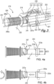
- Figure 1 shows an axially exploded view of a catheter assembly 210 according to the present invention.
- Figure 2 shows an external view of the catheter assembly 210 in a sealed configuration.
- the catheter assembly 210 comprises an external housing 212, a wetting agent storage chamber 228 and a catheter 216.
- the external housing 212, wetting agent storage chamber 228 and catheter 216 are concentrically arranged such that the catheter 216 is located within the storage chamber 228 which is located within the external housing 212 in a radially nested configuration.
- the external housing 212 comprises a main body 218 in which at least a portion of the storage chamber 228 and catheter 216 are housed, and a cap 220 which is detachable so as to be removed by a user prior to use. Removal of the cap 220 exposes the catheter 216 for withdrawal from the external housing 212 for use.
- the main body 218 may further comprise a catheter tube section 219 and a storage chamber section 221.
- the catheter tube section 221 houses the catheter tube 232 of the catheter 216.
- the storage chamber section 221 houses the storage chamber 230.
- the catheter tube section 219 and storage chamber section 221 may comprise separate components which are attached together to provide the main body portion 218, or may be provided by parts of a unitary structure. It will be appreciated that portions of the storage chamber section 219 may house portions of the catheter tube 232 and catheter tube section 221 may house portions of the storage chamber 228.
- the catheter tube section 221 will provide the terminal proximal end of the housing 212.
- the external housing 212 provides an enclosed volume in which the catheter 216 can be housed for storage and transportation prior to use.
- the main body 218 and cap 220 may provide a sterile cavity in which the catheter 216 is located.
- the external housing 212 is generally elongate having a longitudinal axis 222 which can be taken to be the principal axis of the catheter assembly 210 which is coaxial with the longitudinal axis of the storage chamber 228 and catheter 216.
- the enclosed volume provided by the external housing 212 is defined by an external wall of the housing 212 which extends from a first proximal end 213, which receives an insertion end 224 of the catheter 216, to a second distal end 215 in which a catheter outlet end 226 is received.
- the second end 215 is provided by the cap 220.
- the external profile of the housing 212 can be any required for aesthetic or functional purposes and may incorporate similar external features to the external housing 212 described above.
- the external housing 212 may be generally cylindrical, tapering towards the first end to aid insertion into a storage receptacle or pocket, for example, and tapering towards the second end along the length of the cap 220. Additionally, the cap 220 may be temporarily stored on the opposing end of the external housing 212.
- a hermetic seal may be provided between the cap 220 and main body 218 to preserve the sterility of the internal volume of the external housing 212, prior to use.
- the hermetic seal may comprise a sealing element, such as an O-ring seal 297b provided between the main body 218 and cap 220 as best seen in figure 3 , in which case the O-ring seal sits on a circumferential sealing surface on the outside of the main body 218, which, when the cap 220 is sealed faces a corresponding circumferential sealing surface on the inside of the cap.
- a hermetic seal may be provided by a tamper proof connection or strip between the main body 218 and cap 220.
- An example of a hermetic seal 297a formed as a tamper proof strip is provided in Figure 2 .
- the seal 297a comprises a portion of the external surface of the external housing 212.
- the external housing 212 may comprise a main body 218, a cap 220 and a hermetic seal 297a.
- the hermetic seal 297a/b may be configured such that rotating cap 220 breaks the seal 297a. Breaking the seal 297a/b may be done during a priming step which puts the catheter assembly into a primed configuration.
- the storage chamber 228 provides a reservoir for the storage of a wetting agent prior to the wetting of the catheter tube 232.
- the storage chamber 228 is provided at a distal end of the catheter tube 232 such that the catheter tube 232 may be drawn through wetting agent retained within the storage chamber 228 when the catheter is being withdrawn from the housing 212.
- the wetting agent may flow down the exterior surface of catheter tube 232 (which as in the previous embodiment may be functionalised so as to be hydrophilic) towards the closed end of the main body 218
- the storage chamber 228 surrounds the catheter 216 and comprises a chamber wall 231, 235 which seals against seal surfaces 239, 241 provided on the catheter 216 and provides an annular enclosed volume in which the wetting agent is stored prior to use.
- the storage chamber wall 231, 235 is sealed against the catheter 216 using first and second seals 233, 237 which are axially separated and may be provided at the distal and proximal ends of the storage chamber 228.
- first and second seals 233, 237 which are axially separated and may be provided at the distal and proximal ends of the storage chamber 228.
- the catheter 216 therefore comprises, a movable insert such that it can be moved relative to the storage chamber wall 231.
- the catheter 216 may be configured such that it is axially movable when rotated.
- the rotation of the catheter 216 may be achieved by via rotating the cap 220.
- the cap 220 and catheter 216 may be rotatably engaged.
- the chamber wall 231, 235 may comprise multiple components which are joined together to provide a sealed external wall to provide the enclosed volume which is sealed against the catheter 216.
- the storage chamber section 219 may be configured to prevent relative rotation of the storage chamber 228.
- the storage chamber section 219 prevents the storage chamber 228 from rotating about the longitudinal axis 222.
- the catheter 216 which passes through the storage chamber 228 can be rotated relative to the housing 212 and storage chamber 228 during a release and/or wetting procedure.
- the storage chamber section 219 may also be configured to prevent axial movement of the storage chamber 228 during a release and/or wetting procedure.
- the axial retention of the storage chamber 228 may be limited to be below a predetermined threshold such that when an axial pulling force above the predetermined threshold is achieved, the storage chamber 228 is released from the housing 212 and able to move axially.
- the storage chamber 228 may be an elongate structure which extends coaxially along the longitudinal axis 222 to define an annular cavity in which the wetting agent may be stored.
- the annular cavity is defined by a radially outer wall with axially facing end walls which extend between the radially outer wall and catheter 216.
- the end walls may extend from the ends of the radially outer wall in the normal plane of the longitudinal axis 222, but this is not a limitation and other configurations are envisaged.
- the end walls may comprise or terminate at the radially inner edge in axially extending annular flanges at either or both ends of the storage chamber. An embodiment of these is described in further detail below.
- the movable insert is configured to move axially along the longitudinal axis 222 with respect to the chamber wall 231.
- the movement of the catheter 216 may transition the catheter 216 between a first position and a second position.
- the storage chamber 228 is sealed by the seal element 233a located between the chamber wall 231 and the catheter 216.
- the seal element 233a is aligned with sealing surfaces 233b in the first position.
- the sealing element 233a is configured to be axially misaligned with at the sealing surface 233b.
- the seal 233 can be opened in the second position, or as described below, the compression of the seal element 233a can be reduced such that the storage chamber 228 remains sealed, but the catheter 216 may be withdrawn more readily to effect the wetting of the catheter tube 232.
- the seal element 233a and sealing surface 233b are shown as being placed on the chamber wall 231 and catheter body 243 respectively, this may not be the case and they may by the other way round.
- the first and second seals 233 and 237 are axially separated and seal against a portion of the catheter 216.
- At least one of the movable insert, e.g. the a portion of the catheter 216, and the chamber wall 231 may comprise a divergent portion over which the seal element 233a passes when transitioning between the first sealed position and second primed position.
- the divergent portion is such that the distance between the chamber wall 231 and movable insert at the axial location of the seal element 233a is increased when in the second primed position.
- the distance may be a radial distance with respect to the longitudinal axis 222.
- the divergent portion may comprise a widening of a cavity adjacent to the seal surface 233a.
- the divergence may be provided by a step or taper adjacent to the sealing surface.
- Figures 4a and 4b show a side view of the catheter 216 with the first 233 and second 237 seals shown in section.
- Figure 4a shows the position of the catheter 216 in a sealed/storage configuration
- Figure 4b shows the catheter 216 in a primed configuration.
- the primed configuration is one in which the catheter 216 is configured to be removed from the external housing during a second stage of the catheter 216 deployment, (the first stage being the priming).
- first 233 and second 237 seals may be provided by respective seal elements 233a and 237a which are located against an opposing seal surface 233b and 237b on the catheter 216.
- the sealing surfaces 233b and 237b may be considered to be primary sealing surfaces.
- the seal surfaces 233b and 237b are provided by a catheter body 243.
- the body 243 thus constitutes the moveable insert and is provided between the outlet end 236 of the catheter 216 and the catheter tube 232.
- the catheter body 243 may have an increased radius compared to the catheter tube 232 and is profiled to provide the seal surfaces 233b and 237b.
- the catheter body 243 may extend to the distal end of the catheter 216 and be an extension thereof.
- the distal end of the catheter body 243 may provide the outlet of the catheter 216 which may be shaped externally and internally to provide the external handling surfaces and internal flow enhancing features.
- the exterior of the catheter body 243 may include an external handling surface which includes a plurality of grooves which aid the handling of the catheter by a user's finger tips.
- the internal surface may also include a funnel which diverges in a flow direction.
- the first seal surface 233b is provided at a proximal end of the catheter body 243 and storage chamber 228 and provide a raised portion against which the seal element 233a resides when in a sealed configuration.
- the raised portion includes a first diameter D233 which is greater than a diameter d233 on an adjacent portion of the catheter body 243 on proximal side and, optionally, distal side.
- the sealing surface 233b is separated by a step or chamber in the profile of the catheter body 243.
- the seal surface 233b and adjacent portion are shown as being cylindrical.
- the seal surface 233b comprises a cylindrical surface having a first radius with the adjacent proximal surface being provided by a second radius which is smaller than the first radius.
- the seal contact is maintained with the compressive force, and thus axial retention, on the catheter body 243 and catheter 216 being reduced.
- the proximal shaft of the catheter body 243 may provide a secondary proximal seal surface 233c.
- the seal 233 may act to provide an increased sealing pressure which can help reduce the evaporation loss from the storage chamber 228.
- the distal seal 237 comprises a distal seal element 237a which is sealably located against a seal surface 237b provided by the catheter body 243.
- the distal seal surface 237b is provided by a constant cross-section such that a constant seal 237 is maintained when there is relative axial movement between the catheter 216 and storage chamber 228.
- the distal seal surface 237b may be defined by radial upstands which locate the seal element 237a with a defined axial range of the catheter body 243.
- the radial upstands may be provided as part of a groove within a surface of the catheter body 237, one or more flanges, or an increase in the diameter of the catheter body 243.
- Figures 4a and 4b show a distal sealing surface 237b having a combination of a radial flange being provided on the righthand, proximal, side, an increase in diameter being provided on the left hand, distal, side, with the seat of the seal surface 237b being provided as a groove in the surface of the catheter body 243 shaft which extends between the first 233 and second seals 237.
- the storage chamber 228 may comprise features to retain the seal elements 233a and 237a in place and urge the seal elements 233a and 237a radially inwards to provide the seal.
- the seals 237a and 233a may be retained by a seal housing and may be overmoulded.
- a specific embodiment pertaining the retention of seal element 233a is provided below in connection with Figure 6a .
- the seal elements 233a and 237a may be different sizes. More specifically, the proximal seal 233 may comprise a larger seal element 233a to allow for the increased compression and increased contact area with the sealing surface 233b when in the first sealed configuration.
- the seal elements 233a and/or 237a may comprise an elastomeric material.
- the seal elements 233a and 237b may be O-rings, alternatively they could be X-rings or U-cups, or other similar annular seal.
- the catheter 216 is configured to move axially relative to the external housing 212 and storage chamber 228. This not only allows the catheter 216 to be withdrawn from the external housing 212 for use, but also allows the catheter tube 232 to pass through the wetting agent housed in the storage chamber 228. Thus, the catheter 216 has a sealed (or storage) configuration and a primed configuration from which the catheter 216 is withdrawn and wetted.
- the sealed configuration of the catheter assembly 210 and catheter 216 is shown in Figures 2 and 4a respectively. As described above, the primed configuration prior to the withdrawal of the catheter 216 is shown in Figures 3 and 4b .
- the movement of the catheter 216 from the sealed configuration to the primed configuration may be achieved by a user axially withdrawing the catheter 216 in the distal direction.
- the withdrawal may be achieved by the user gripping the outlet end 226 of the catheter either directly, or indirectly, for example, via the cap 220.
- the axial withdrawal may be achieved using an actuator.
- the actuator may be referred to as a priming mechanism.
- the priming mechanism comprise any device which can cause the required axial movement of the catheter 216 in relation to the external housing 212 and storage chamber 228.
- the priming mechanism may comprise the catheter which is configured to be rotatable such that the rotating induces the axial movement.
- the priming mechanism may comprise a cam drive or crank in which a drive surface engages with a drive element such that relative rotation of the driving element or drive surface results in the axial motion of the catheter 216 relative to the main body 218.
- the rotational movement may be provided by a rotatable actuator such as the cap 220 which may be rotationally engaged with the catheter 216 as the movable insert.
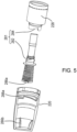
- FIG. 5 shows an embodiment in which the catheter body 243 is provided with a cam drive 281.
- the cam drive comprises a drive surface in the form of a ramp formation provided by an axially facing end wall surface of the storage chamber wall 231, and a driving element comprising circumferentially extending fins 282 which extend axially and circumferentially so as to provide a helical projection which is functions as a screw thread/cam.
- the fins 282 engage with the corresponding ramp formations 284 provided on the storage chamber 228 such that rotating the catheter 216 causes the fins 282 to travel along the ramp formations 284 and urge the catheter 216 distally relative to the storage chamber 228.
- Urging the catheter 216 distally results in an axial sliding of the catheter 216 relative to the storage chamber seals 233 and 237 and the movement of the proximal seal element 233a and the associated seal surface 233b, as described above in relation to Figures 4a and 4b .
- the rotation of the catheter 216 may be achieved by the user gripping and rotating the external handling surface of the catheter outlet end 226, or via a rotation of the cap 220.
- Rotating the cap 220 may be achieved by providing a rotational engagement between the cap 220 and the catheter body 243.
- the rotational engagement may be provided via corresponding radial projections 286a and 286b on the catheter body 243 and the interior of the cap 220.
- the projections may take any suitable form and may comprise radially extending members in the form of ribs, flanges, projections, pins, pedestals etc. as noted above, the projections may serve a dual purpose, also assisting in retaining the cap 220 on the base of the main body 218 during catheterisation.
- the cap 220 is also shown as comprising screw threads 288a which engage with corresponding screw threads 288b provided on the exterior of the distal end of the main body 218 such that the cap 220 can be releasably attached to the main body 218.
- the cap 220 can be removed axially off the main body 218 with the projections 286a and 286b becoming axially separated.
- the fins 282 travel circumferentially over the end of the ramp formations and no further axial movement occurs.
- the priming mechanism shown in Figure 5 comprises a plurality of helical fins 282, e.g. two, which engage with a corresponding number of ramp formations 284 on the storage chamber 228, it will be appreciated that the number of the drive surface/driving elements may be varied. Further, the helical surfaces which provide cam-like action may be provided by any suitable formations and the embodiments of fins and ramp formations are only provided as examples. For example, both storage chamber 228 and catheter 216 could be provided with ramp formations and/or fins, or some combination thereof. Other cam-like arrangements which translate rotational movement into linear axial movement may be provided, such as screw threads similar to those provided for the engagement of the cap 220 and main body 218.
- Figures 3 , 6a and 6b show an embodiment of how the storage chamber 228 may be constructed in more detail.
- a storage chamber 228 provided by multi-part construction in which a first part 231 and a second part 235 are joined together to provide the storage chamber wall.
- Figure 3 shows the two-part construction in which the first distal part 231 is fitted to a second proximal part 235.
- the proximal part 235 comprises a radially extending wall which provides the terminal axial end wall of the storage chamber compartment in which the majority of the wetting agent is located.
- the distal part 231 comprises a distal end wall of the storage chamber compartment and the radially outer wall.
- the internal surface of the storage chamber wall comprises a plurality of radial projections in the form of fins 290.
- the fins 290 are circumferentially distributed so as to be angularly separated from one another about the longitudinal axis 222.
- the fins 290 extend axially and radially so as to lie in a plane defined by the longitudinal axis 222 of the catheter assembly.
- the fins 290 may be provided in diametrically opposed pairs.
- the radially inner edges 291 of the fins 290 may be provided at a common radial distance from the central longitudinal axis 222 of the catheter 216 such that, in combination, the radial inner edges 291 of the fins 290 provide a guide tube to keep the catheter 216 and storage chamber 228 concentrically aligned.
- the radius of the guide tube may correspond to or be larger than the proximal sealing surface 233b such that the sealing surface 233b can pass unhindered therethrough whilst maintaining concentricity.
- proximal axial edges 292 of the fins 290 which define the axial extent of the fins 290 terminates short of the proximal end wall of the storage chamber 228 so as to provide edges 292 which define a void in which the proximal seal element 233a is provided.
- the proximal axial edges 292 of the fins 290 provide, in combination, a seat against which the seal element 233a can be located during assembly of the storage chamber 228 and also during use such that the proximal seal is axially restrained during the transition of the catheter 216 from the stowed position to the wetting position and during the withdrawal of the catheter 216.
- FIG. 6a shows only four fins 290 in the sectional view, it will be appreciated that a fewer or greater number of fins 290 may be used. It will also be appreciated that although fins 290 provide a convenient structure between which the wetting agent can be stored whilst providing suitable strength and surface area for guiding the catheter and/or providing a seal seat, other formations may be used. For example, the formations may be provided by any combination of projections such as ribs, pins, pedestals or flanges for example.
- the distal end of the storage chamber 228 may be provided with one or more features which are used as part of a priming mechanism 281.
- the distal end of the storage chamber 228 in Figures 16a and 16b comprises the ramp formations 284 which engage with the helical fins 282 provided on the catheter body 243.
- the ramp formations 282 are provided at the terminal end of an annular flange 293 which extends from the main storage compartment.
- the ramp formations 282 are provided by triangular cut-outs in the annular flange 282, with the hypotenuse of the triangle providing the engaging surface.
- the use of the annular flange 282 allows the ramp formations to be located in a close radial proximity to the catheter 216 which allows the corresponding fins 282 to be smaller.
- the annular flange 282 also provides a convenient location for the distal seal 237 which resides between the ramp formations 284 and distal radial wall of the main storage compartment of the storage chamber 228.
- the attachment of the first 231 and second 235 parts of the storage chamber 228 can be via any suitable connection such as: an interference fit, e.g. a push-fit or click-fit; by adhesion; welding; screw thread or clamp, for example.
- an interference fit e.g. a push-fit or click-fit
- the embodiment of Figures 13, 16a and 16b is shown as being a click-fit attachment in which the parts 231, 235 are pushed and clicked together such that a circumferential rib is located within a corresponding groove.
- the external surface of the proximal part 235 is configured to provide an insertion guide 225.
- the external surface may be rounded and/or tapered such that it can be utilised to comfortably locate the insertion guide 225 in the entrance to the urethra.
- the insertion guide 225 (which may be referred to as a gripper) may be an annular member located radially outwardly of the catheter tube 232 or catheter body 243 when stowed.
- the radially outer surface of the insertion guide 225 may be configured to be gripped by a user's fingers and may include one or more surface features, such as annular grooves (not shown) for improving grip and user dexterity.
- the insertion guide 225 is configured to remain external to the urethra when the catheter tube 232 is inserted and so is retractable. Hence, the catheter tube 232 can pass through the insertion guide 225 such that the insertion guide 225 moves rearwards to towards the outlet end 226 during insertion. When fully retracted, the insertion guide 225 may abut the distal end of the catheter body 243.
- the storage chamber comprises an insertion guide 225
- the storage chamber 228 complete with insertion guide 225 may be released from the external housing when the catheter 216 is withdrawn.
- the storage chamber 228 may be retained within the external housing 212 whilst the catheter 216 is removed and the proximal end of the catheter tube 232 is aligned with the insertion guide 225.
- the catheter arrangement 210 may comprise an optional retractable sheath 234 located radially outside of the catheter tube 232. Alternatively, the insertion guide could simply be pulled out by hand.
- Figures 1 and 9 show a retractable sheath 234 in a stowed configuration.
- the sheath 234 extends from an attachment 234a on the catheter body 243 to an attachment 234b on the distal side of the storage chamber 228.
- the sheath 234 is flexible and retractable with the insertion guide 225.
- the sheath 234 when the catheter 216 and insertion guide 225 are located within the housing 212, the sheath 234 is provided in a stowed configuration which is depicted in Figure 1 , and when the catheter 216 is withdrawn, the sheath unfurls from the stowed configuration to a deployed configuration in which it is fully extended and acts to tether the storage chamber to the catheter such that a continued withdrawal of the sheath 234 results in the withdrawal of the storage chamber and insertion guide 225.
- the storage chamber 228 may not comprise the proximal annular flange which forms part of the proximal part 235, and may not be retained within the housing 212 when the catheter 216 is removed. In such a case, the sheath 234 may also be omitted.
- the storage chamber 228 may be retained within the external housing 212 by a releasable coupling 295, (as best seen in Figure 8 and described below).
- the releasable coupling 295 may release the storage chamber 228 when a predetermined amount of axial tension, i.e. a withdrawing pulling force on the storage chamber is applied or exceeded. Once the predetermined amount of axial tension has been applied or exceeded, the storage chamber may be released by the releasable coupling and withdrawn from the external housing.
- the axial tension may be applied to the storage chamber 228 directly or indirectly.
- a user may grip the storage chamber 228 or a portion thereof and withdraw it, together with the catheter 216.
- the storage chamber 228 and catheter 216 may be coupled together such that withdrawing of the catheter 216 causes the storage chamber 228 to be withdrawn from the external housing 212.
- the coupling between the storage chamber and catheter may be provided by a tether such as the retractable sheath 234.
- the storage chamber 228 may be rotationally fixed to the main body 218.
- An embodiment of a coupling 295 configured prevent relative rotation is described in connection with Figures 6b , which shows the exterior of the storage chamber 228; Figure 7 , which shows the storage chamber section 219 without the storage chamber 228 housed therein; and Figure 8 which shows the storage chamber 228 and storage chamber section 219 combined.
- the coupling 295 may be configured to be a releasable coupling, such that the coupling 295 is released once a predetermined force threshold is exceeded in the axial direction.
- the exterior of the storage chamber 228 may be provided by an external surface 294 which, in the described embodiment, is generally cylindrical.
- the external surface 294 may comprise one or more anti-rotation and/or axial retention features such as a one or more recesses.
- a plurality of circumferential recesses may be provided such those provided by the castellated annular groove 296.
- the storage chamber section 219 may comprise an elongate tubular member which extends from proximal end to a distal end.
- the external surface of the storage member section 219 may provide a portion of the external surface of the external housing 212 and/or one or more features for attaching the cap 220 to the main body 218 such as the aforementioned screw threads 288b, and/or one or more features 297 for receiving a hermetic seal 297a shown in Figure 1 which may be provided between the corresponding terminal ends of the cap 220 and main body 218 and which is irreversibly removed or broken as the cap 220 is removed, as well known in the art.
- the interior of the storage chamber section 219 comprises a cylindrical cavity 219a in which the storage chamber 228 is received and may include one or more features of the coupling 295 for engaging the storage chamber 228 to prevent axial and/or radial movement of the storage chamber 228 relative to the housing 212.
- the coupling 295 part provided by the storage chamber section 219 comprises a plurality of circumferentially distributed prongs 298 which are substantially rotationally rigid to the extent where they act in combination to prevent rotation of the storage chamber when engaged in annular castellated groove 296, and radially compliant such that, when the storage chamber 228 and chamber storage section 219 are urged axially apart, the prongs 298 flex outwardly thereby releasing the storage chamber 228. When under the predetermined axial force threshold, the prongs 298 remain engaged with the castellated groove 296 on the external surface 295 of the storage chamber wall.
- the number of prongs in Figures 7 and 8 is eight. However, the number may be greater or fewer than this in some embodiments.
- the castellated groove 296 comprises an annular groove which extends around the external surface 294 of the storage chamber 228 and is partitioned so as to provide and a circular array of recesses in which the tips of the prongs 298 can be received. It will be appreciated that in other embodiments, the recesses may be fewer in number and more dispersed than shown.
- the prongs 298 comprise projections having a limb 298a and a tip portion 298b.
- the limb 298a extends axially towards the proximal end of the main body 218 from a radially extending internal surface of the storage chamber section 219.
- the limbs 298a extend from a distal fixed end to a proximal free end.
- the free end includes the tip portion 298b which extends radially inwards to provide hooks which are received in the recesses of the storage chamber external surface 294 so as to provide a clasp.
- the radially inner surface of the storage chamber section which receives the storage chamber 228 is flush with the internal surface of the cylindrical housing in which the storage chamber is received.
- the radially inner edge of the proximal end of the prong tip portions 298b are tapered such that prongs 298 can more readily receive and be urged apart by the storage chamber 228 when the storage chamber 228 is inserted into the storage chamber section 219 along the longitudinal axis.
- the releasably coupling requires an increased axial force to activate.
- the increase in force ensures that the catheter tube is fully withdrawn such that the storage chamber 228/insertion guide 225 is in the correct location relative to the insertion end and that the retractable sheath is fully extended. It may also provide mechanical feedback to the user to indicate that the catheter has been withdrawn to its full extent and can be reinserted if required.
- the storage chamber 228 when the storage chamber 228 is left within the housing 212 following the withdrawal of the catheter 216, the storage chamber 228 may be attached to or form part of the housing 212 and the coupling 295 may not be required.
- a user may rotate the cap 220 to break the hermetic seal 297a/297b.
- the rotation of the cap 220 results in the rotation of the catheter 216 via the rotational engagement provided by radially projections 286a and 286b.
- the rotation of the catheter 216 results in the drive surface and driving elements provided by cam drive 281 urging the storage chamber 228 and catheter 216 axially apart and an axial sliding of the proximal seal element 233a to provide the catheter assembly in a primed configuration.
- This requires a first step in which a single action from a user, i.e. the rotation of the cap 220 in a first direction transitions the catheter assembly from a sealed configuration to a primed configuration.
- the catheter 216 may be axially withdrawn through the storage chamber 228 which functionally acts as a wetting chamber during the withdrawal. If required, the catheter may be reinserted into the storage chamber 228 and withdrawn multiple times to ensure a complete wetting of the catheter tube 232 prior to removal.
- the insertion guide 225 may form part of the storage chamber 228 and may be removed from the housing 212 with the catheter 216.
- a seal of the storage chamber is advantageous as the mechanical advantage of using a priming mechanism allows the seal to be tighter. Without the mechanical advantage of the priming mechanism, the tighter more effect seal would be difficult to displace by hand, particularly for weaker or more infirm users.
- the embodiments are all female intermittent urinary catheters, with an exemplary length of between 90mm to 200mm. e.g. between 130mm and 155mm, such as about 135mm and the catheter assemblies have a length corresponding to the length of the catheter, such as a closed length of the casing of between 2mm and 10mm longer than the length of catheter (e.g. 10-25cm; between 140mm and 165mm, such as 142mm), it is considered that teachings could be applied to male urinary intermittent catheters (which are typically longer) or even other types of catheter.
- the embodiments have functionalised hydrophilic surfaces which become slippery when wetted with a wetting agent such as water, the wetting agent could be a lubricant instead.
Landscapes
- Health & Medical Sciences (AREA)
- Life Sciences & Earth Sciences (AREA)
- Biophysics (AREA)
- Pulmonology (AREA)
- Engineering & Computer Science (AREA)
- Anesthesiology (AREA)
- Biomedical Technology (AREA)
- Heart & Thoracic Surgery (AREA)
- Hematology (AREA)
- Animal Behavior & Ethology (AREA)
- General Health & Medical Sciences (AREA)
- Public Health (AREA)
- Veterinary Medicine (AREA)
- Epidemiology (AREA)
- Urology & Nephrology (AREA)
- Infusion, Injection, And Reservoir Apparatuses (AREA)
- Media Introduction/Drainage Providing Device (AREA)
- External Artificial Organs (AREA)
Abstract
An intermittent catheter, preferably a female intermittent catheter, is provided in an assembly. The assembly comprising a wetting agent storage chamber with at least one projection configured to guide the catheter within the wetting agent storage chamber. The at least one projection retains a seal element in the wetting agent storage chamber during withdrawal of the catheter. The wetting agent storage chamber comprises at least one radially extending end wall and the at least one projection extends axially within the wetting agent storage chamber, the at least one projection terminating short of the end wall to define a void wherein the seal element is seated in the void.
Description
- The present invention relates to an intermittent catheter (e.g. a urinary catheter).
- A catheter is a medical device comprising a hollow catheter tube designed for insertion into canals, vessels, passageways or body cavities to permit injection, drainage or withdrawal of fluids or substances therefrom, or to ensure said canals, vessels, passageways etc. remain open. Urinary catheters are designed for use for insertion into a user's bladder via the urethra to drain the bladder.
- To maximise comfort and minimise the risk of trauma and/or infection, an outer surface of the catheter tube is typically wetted using a wetting agent prior to insertion by the user. In further developments, the catheter tube itself comprises, is integrated with or is coated with a hydrophilic component (e.g. a hydrophilic polymer) which serves to reduce friction further upon application of the wetting agent.
- Some catheters may be supplied pre-wetted in a packaging, for instance, where the catheter is at least partially submerged within wetting agent within the packaging. Whilst this may ensure the catheter tube is adequately wetted prior to use, such arrangements suffer in that components of the catheter other than the catheter tube such as a gripper element or funnel can also become wetted. This has a detrimental effect of the experience of the user where it may become difficult to hold and direct the catheter tube as required. This is particularly problematic where the user is performing self-catheterisation. Further, having the catheter submerged may effectively reduce the shelf-life of the catheter due to long-term exposure of components of the catheter to moisture.
- It is therefore seen advantageous to provide a catheter which may be wetted at or immediately prior to the point of use.
- In an attempt to address this, some catheters are provided in packaging which includes a rupturable container or sachet within the packaging which a user may burst to release the wetting agent. Typicaly, this involves the user squeezing the packaging to cause the container/sachet to break. However, such arrangements experience similar problems to those discussed above where the wetting agent is allowed to come into contact with other components of the catheter. Such arrangements also result in the possibility of the catheter tube not being fully wetted, or indeed wetted at all, prior to use. This can be harmful for the user.
- It is therefore advantageous to provide a cathater which includes a means of supplying a wetting agent solely to the catheter tube to improve user experience.
-
US5454798A describes a disposable urine bag having sealed cavity members where one cavity stores an extendable catheter and also acts as a urine storage reservoir. A second sealed and peel-away cavity includes a catheter advancement mechanism which provides for lubricated catheter advancement without actual contact of the catheter by the human hand. An absorption member is provided to semi-solidify urine stored in the urine storage reservoir. -
WO2011/079129A1 describes a catheter assembly including an elongate member having a proximal end and a distal end. The distal end having at least one drainage opening. A fluid containing member arranged on the elongate member. A container containing the elongate member and the fluid containing member. -
WO2015/084923A describes a catheter assembly including a catheter at least partially positioned within a sleeve. The catheter has a coating, which produces a low-friction surface on the catheter when treated with an activating fluid. A protective tip is connected to the proximal end of the sleeve and has proximal and distal internal seals, with the proximal seal at the proximal end of the tip or between proximal and distal ends of the protective tip. A cap of the assembly has a projection, which is removably received within the protective tip for sealing engagement with the proximal and distal seals to define a fluid reservoir within the protective tip. An activating fluid is contained within the fluid reservoir. The projection may be partially hollow to receive a portion of the catheter. The sleeve may be relatively narrow or at least have a narrowed portion for better distribution of activating fluid to the surface of the catheter. - In further prior art solutions, the catheter may be packaged within a packaging which includes a wetting device. In use, the catheter tube may be moved through the wetting device as the catheter is removed from the packaging and in doing so wetting the catheter tube. Examples of such catheters are shown in PCT application No. PCT/IB2018/001539 in the name of ConvaTec Limited.
- However, due to packaging constraints the amount of wetting agent able to be contained in such wetting devices is low, and there therefore remains a possibility of the catheter tube not being fully wetted in such solutions, especially where the catheter is near the end of its shelf life and some of the solution may have evaporated.
- For mechanisms which wet the catheter tube from the distal end, an insufficient volume of wetting agent may result in the tip end not being wetted at all which is undesirable since the tip end will be introduced into the urethra first and is hence most likely to cause injury if inadequately wetted before use.
- Further a minamum length of catheter is required for regulatory approval and it is desirable to ensure that the length is wetted with a minimum impact on the packaging size.
- It is an aim of an embodiment or embodiments of the invention to overcome or at least partially mitigate one or more problems with the prior art and/or to provide an improved intermittent catheter.
- The present invention provides a catheter assembly according to the appended claims.
- An aspect of the present disclosure provides a catheter assembly comprising a catheter; and a wetting agent storage chamber in which the catheter is located, wherein the wetting agent storage chamber comprises at least one projection configured to guide the catheter within the wetting agent storage chamber, wherein the at least one projection retains a seal element in the wetting agent storage chamber, wherein the chamber comprises at least one radially extending end wall and at least one projection extending axially within the wetting agent storage chamber, the at least one projection terminating short of the end wall to define a void, wherein the seal element is seated in the void.
- Providing a storage chamber having one or more features such as a projection to locate the catheter within the wetting chamber during withdrawal or reinsertion allows the positioning of the catheter to be controlled which provides for an improved wetting of a catheter tube of the catheter. During reinsertion it also ensures the catheter does not become trapped within the wetting agent storage chamber.
- Providing a wetting agent storage chamber having one or more features such as a projection to locate a seal element therein can provide a convenient way to locate the seal element and maintain its relation to the wetting agent storage chamber during withdrawal of a catheter of the catheter assembly. This is beneficial as it ensures the seal element is correctly located upon reinsertion of the catheter into the wetting agent storage chamber, ensuring a seal is maintained after reinsertion. It also avoids the seal element being carried out on the catheter, which would obviously cause problems on insertion of the catheter into the urethra.
- The at least one projection may comprise a plurality of ribs or fins. The plurality of ribs or fins may extend axially and radially. The at least one projection may comprise a plurality of pins. The at least one projection may comprise a plurality of pedestals. The at least one projection may comprise a plurality of flanges. The plurality of projections may comprise any combination of ribs and/or fins and/or pins and/or pedestals and/or flanges.
- The storage chamber may comprise an axially extending radially outer wall and at least one radially extending end wall. The storage chamber may comprise a first radially extending end wall and a second radially extending end wall. The end walls may comprise one or more tubular flanges extending axially therefrom.
- The plurality of projections may extend from either or both of the radially outer wall or the at least one end wall. The plurality of projections may extend radially inwards from the radially outer wall of the wetting agent storage chamber. The plurality of projections may be circumferentially distributed. There may be at least 2 projections. There may be at least 3 projections. There may be at least 4 projections. There may be at least 6 projections. There may be at least 8 projections. There may be 4 projections.
- The catheter and storage chamber may be concentrically aligned.
- The projections may be shaped to define a void. The void may be defined by a discontinuity in the projections. The projections may only partially extend along the axial extent of the storage chamber. The void may be partially defined by an axial edge of the projections. The void may be partially defined by an end wall of the storage chamber. The discontinuity may be provided by a first portion of each projection extending radially inwards by a first amount and a second portion of each projection extending radially inwards by a second, lesser amount.
- The catheter may define a longitudinal axis and the each of the plurality of projections may lie in a plane defined by the longitudinal axis. The plurality of projections may be provided in diametrically opposing pairs.
- The seal element may be elastomeric. The seal element may be annular. The seal element may be an O-ring. The seal element may be an X-ring or similar annular seal device. The seal element may be a U-cup seal.
- The O-ring may be arranged in the void. The axial edges of the projections may define a seat for the seal element. The seat may axially restrain the seal element during transition of the catheter from a stowed position to a wetting position. The seat may axially restrain the seal element during withdrawal of the catheter. This is beneficial as it ensures the seal element is correctly located upon reinsertion of the catheter into the wetting agent storage chamber, ensuring a seal is maintained after reinsertion. It also avoids the seal element being carried out on the catheter, which would obviously cause problems on insertion of the catheter into the urethra.
- The wetting agent storage chamber may comprise two openings arranged at opposing axial ends of the wetting agent storage chamber through which the catheter may pass. The projections may define a channel between the two openings.
- The radially inner edges of the projections may define a guide for guiding the passage of the catheter during a withdrawal or re-passing/re-insertion of the catheter. The guide may extend at least 50% of the distance between the two openings, preferably the guide may extend at least 80% of the distance between the two openings. The guide may extend at least 40% of the distance between the two openings. The guide may extend at least 50% of the distance between the two openings. The guide may extend at least 60% of the distance between the two openings. The guide may extend at least 70% of the distance between the two openings.
- The separation between the radially inner edges of adjacent projections may be less than the diameter of the catheter. By ensuring the separation between the radially inner edges of adjacent protections being less than the diameter of the catheter, the catheter is restricted from deviating from the channel defined by the projections.
- The diameter of the guide may be approximately equal to the diameter of one or more openings of the wetting chamber. The diameter of the guide may be approximately equal to the diameter of sealing surface of the moveable insert. The diameter of the guide may be larger than the diameter of sealing surface of the moveable insert.
- Optional features set out above may apply to any aspect of the invention. Thus, for example, the preferred length of the catheter and assembly is only described once above, but applies to all aspects and combinations of aspects and other optional features
- In order that the invention may be more clearly understood one or more embodiments thereof will now be described, by way of example only, with reference to the accompanying drawings, of which:
-
Figure 1 shows a longitudinally exploded view of a catheter assembly according to an embodiment of the disclosure; -
Figure 2 shows a perspective view of the catheter assembly ofFigure 1 ; -
Figure 3 shows a partial cross-sectional view of the catheter assembly ofFigure 1 showing a wetting agent storage chamber; -
Figures 4a and 4b show schematic longitudinal sections of the catheter assembly ofFigure 3 in a sealed and primed configuration respectively; -
Figure 5 shows a longitudinally exploded view of a rotatable actuator, storage chamber and movable insert according to an embodiment; -
Figures 6a and 6b show a storage chamber according to an embodiment; -
Figures 7 and 8 show an example of a storage chamber and releasable coupling; and -
Figure 9 shows a partial longitudinal sectional view of a retractable sheath in a stowed configuration. -
Figure 1 shows an axially exploded view of acatheter assembly 210 according to the present invention.Figure 2 shows an external view of thecatheter assembly 210 in a sealed configuration. Thecatheter assembly 210 comprises anexternal housing 212, a wettingagent storage chamber 228 and acatheter 216. Theexternal housing 212, wettingagent storage chamber 228 andcatheter 216 are concentrically arranged such that thecatheter 216 is located within thestorage chamber 228 which is located within theexternal housing 212 in a radially nested configuration. - The
external housing 212 comprises amain body 218 in which at least a portion of thestorage chamber 228 andcatheter 216 are housed, and acap 220 which is detachable so as to be removed by a user prior to use. Removal of thecap 220 exposes thecatheter 216 for withdrawal from theexternal housing 212 for use. - The
main body 218 may further comprise acatheter tube section 219 and astorage chamber section 221. Thecatheter tube section 221 houses thecatheter tube 232 of thecatheter 216. Thestorage chamber section 221 houses the storage chamber 230. Thecatheter tube section 219 andstorage chamber section 221 may comprise separate components which are attached together to provide themain body portion 218, or may be provided by parts of a unitary structure. It will be appreciated that portions of thestorage chamber section 219 may house portions of thecatheter tube 232 andcatheter tube section 221 may house portions of thestorage chamber 228. Typically, thecatheter tube section 221 will provide the terminal proximal end of thehousing 212. - The
external housing 212 provides an enclosed volume in which thecatheter 216 can be housed for storage and transportation prior to use. Themain body 218 andcap 220 may provide a sterile cavity in which thecatheter 216 is located. Theexternal housing 212 is generally elongate having alongitudinal axis 222 which can be taken to be the principal axis of thecatheter assembly 210 which is coaxial with the longitudinal axis of thestorage chamber 228 andcatheter 216. - The enclosed volume provided by the
external housing 212 is defined by an external wall of thehousing 212 which extends from a firstproximal end 213, which receives aninsertion end 224 of thecatheter 216, to a seconddistal end 215 in which acatheter outlet end 226 is received. In the embodiment shown, thesecond end 215 is provided by thecap 220. Thus, the removal of thecap 220 exposes theoutlet end 226 of thecatheter 216 such that a user can grip and remove thecatheter 216 from thehousing 212 for use. - The external profile of the
housing 212 can be any required for aesthetic or functional purposes and may incorporate similar external features to theexternal housing 212 described above. Hence, theexternal housing 212 may be generally cylindrical, tapering towards the first end to aid insertion into a storage receptacle or pocket, for example, and tapering towards the second end along the length of thecap 220. Additionally, thecap 220 may be temporarily stored on the opposing end of theexternal housing 212. - A hermetic seal may be provided between the
cap 220 andmain body 218 to preserve the sterility of the internal volume of theexternal housing 212, prior to use. The hermetic seal may comprise a sealing element, such as an O-ring seal 297b provided between themain body 218 andcap 220 as best seen infigure 3 , in which case the O-ring seal sits on a circumferential sealing surface on the outside of themain body 218, which, when thecap 220 is sealed faces a corresponding circumferential sealing surface on the inside of the cap. - In an alternative, a hermetic seal may be provided by a tamper proof connection or strip between the
main body 218 andcap 220. An example of ahermetic seal 297a formed as a tamper proof strip is provided inFigure 2 . Theseal 297a comprises a portion of the external surface of theexternal housing 212. As such, theexternal housing 212 may comprise amain body 218, acap 220 and ahermetic seal 297a. Thehermetic seal 297a/b may be configured such thatrotating cap 220 breaks theseal 297a. Breaking theseal 297a/b may be done during a priming step which puts the catheter assembly into a primed configuration. - The
storage chamber 228 provides a reservoir for the storage of a wetting agent prior to the wetting of thecatheter tube 232. Thestorage chamber 228 is provided at a distal end of thecatheter tube 232 such that thecatheter tube 232 may be drawn through wetting agent retained within thestorage chamber 228 when the catheter is being withdrawn from thehousing 212. Alternatively or additionally, upon opening thestorage chamber 228, the wetting agent may flow down the exterior surface of catheter tube 232 (which as in the previous embodiment may be functionalised so as to be hydrophilic) towards the closed end of themain body 218 - Referring to
Figure 3 thestorage chamber 228 surrounds thecatheter 216 and comprises achamber wall catheter 216 and provides an annular enclosed volume in which the wetting agent is stored prior to use. Thestorage chamber wall catheter 216 using first andsecond seals storage chamber 228. As thecatheter 216 seals thestorage chamber 228, it may be considered to form part of thestorage chamber 228. - The
catheter 216 therefore comprises, a movable insert such that it can be moved relative to thestorage chamber wall 231. Thecatheter 216 may be configured such that it is axially movable when rotated. The rotation of thecatheter 216 may be achieved by via rotating thecap 220. As such, thecap 220 andcatheter 216 may be rotatably engaged. - The
chamber wall catheter 216. - The
storage chamber section 219 may be configured to prevent relative rotation of thestorage chamber 228. Thus, when thecatheter 216 is urged to rotate within thestorage chamber 228, thestorage chamber section 219 prevents thestorage chamber 228 from rotating about thelongitudinal axis 222. As such, thecatheter 216 which passes through thestorage chamber 228 can be rotated relative to thehousing 212 andstorage chamber 228 during a release and/or wetting procedure. - The
storage chamber section 219 may also be configured to prevent axial movement of thestorage chamber 228 during a release and/or wetting procedure. The axial retention of thestorage chamber 228 may be limited to be below a predetermined threshold such that when an axial pulling force above the predetermined threshold is achieved, thestorage chamber 228 is released from thehousing 212 and able to move axially. - As can be seen from
Figure 3 , thestorage chamber 228 may be an elongate structure which extends coaxially along thelongitudinal axis 222 to define an annular cavity in which the wetting agent may be stored. The annular cavity is defined by a radially outer wall with axially facing end walls which extend between the radially outer wall andcatheter 216. The end walls may extend from the ends of the radially outer wall in the normal plane of thelongitudinal axis 222, but this is not a limitation and other configurations are envisaged. The end walls may comprise or terminate at the radially inner edge in axially extending annular flanges at either or both ends of the storage chamber. An embodiment of these is described in further detail below. - As noted above, the movable insert is configured to move axially along the
longitudinal axis 222 with respect to thechamber wall 231. The movement of thecatheter 216 may transition thecatheter 216 between a first position and a second position. In the first position thestorage chamber 228 is sealed by theseal element 233a located between thechamber wall 231 and thecatheter 216. Theseal element 233a is aligned with sealingsurfaces 233b in the first position. In the second position the sealingelement 233a is configured to be axially misaligned with at the sealingsurface 233b. In this way, theseal 233 can be opened in the second position, or as described below, the compression of theseal element 233a can be reduced such that thestorage chamber 228 remains sealed, but thecatheter 216 may be withdrawn more readily to effect the wetting of thecatheter tube 232. Although theseal element 233a and sealingsurface 233b are shown as being placed on thechamber wall 231 andcatheter body 243 respectively, this may not be the case and they may by the other way round. - The first and
second seals catheter 216. At least one of the movable insert, e.g. the a portion of thecatheter 216, and thechamber wall 231 may comprise a divergent portion over which theseal element 233a passes when transitioning between the first sealed position and second primed position. The divergent portion is such that the distance between thechamber wall 231 and movable insert at the axial location of theseal element 233a is increased when in the second primed position. The distance may be a radial distance with respect to thelongitudinal axis 222. The divergent portion may comprise a widening of a cavity adjacent to theseal surface 233a. The divergence may be provided by a step or taper adjacent to the sealing surface. -
Figures 4a and 4b show a side view of thecatheter 216 with the first 233 and second 237 seals shown in section.Figure 4a shows the position of thecatheter 216 in a sealed/storage configuration,Figure 4b shows thecatheter 216 in a primed configuration. The primed configuration is one in which thecatheter 216 is configured to be removed from the external housing during a second stage of thecatheter 216 deployment, (the first stage being the priming). - With reference to
Figures 3, 4a and 4b , the first 233 and second 237 seals may be provided byrespective seal elements seal surface catheter 216. The sealing surfaces 233b and 237b may be considered to be primary sealing surfaces. - In the described embodiment, the seal surfaces 233b and 237b are provided by a
catheter body 243. Thebody 243 thus constitutes the moveable insert and is provided between the outlet end 236 of thecatheter 216 and thecatheter tube 232. As shown, thecatheter body 243 may have an increased radius compared to thecatheter tube 232 and is profiled to provide the seal surfaces 233b and 237b. - The
catheter body 243 may extend to the distal end of thecatheter 216 and be an extension thereof. The distal end of thecatheter body 243 may provide the outlet of thecatheter 216 which may be shaped externally and internally to provide the external handling surfaces and internal flow enhancing features. Hence, the exterior of thecatheter body 243 may include an external handling surface which includes a plurality of grooves which aid the handling of the catheter by a user's finger tips. The internal surface may also include a funnel which diverges in a flow direction. - The
first seal surface 233b is provided at a proximal end of thecatheter body 243 andstorage chamber 228 and provide a raised portion against which theseal element 233a resides when in a sealed configuration. The raised portion includes a first diameter D233 which is greater than a diameter d233 on an adjacent portion of thecatheter body 243 on proximal side and, optionally, distal side. As such, the sealingsurface 233b is separated by a step or chamber in the profile of thecatheter body 243. - In the example shown, the
seal surface 233b and adjacent portion are shown as being cylindrical. Hence, theseal surface 233b comprises a cylindrical surface having a first radius with the adjacent proximal surface being provided by a second radius which is smaller than the first radius. Thus, as shown byFigure 4b , relative axial movement between thecatheter 216 and theseal element 233a which is retained by thestorage chamber 228 moves off theseal surface 233b over the proximally adjacent surface defined by diameter d233, there is either: a separation between theseal element 233a and adjacent surface or a reduced contact which allows the storage chamber to be sealed but the catheter more readily withdrawn. As shown inFigure 4b , the seal contact is maintained with the compressive force, and thus axial retention, on thecatheter body 243 andcatheter 216 being reduced. In this regard, the proximal shaft of thecatheter body 243 may provide a secondaryproximal seal surface 233c. Hence, in the sealed configuration theseal 233 may act to provide an increased sealing pressure which can help reduce the evaporation loss from thestorage chamber 228. - The
distal seal 237 comprises adistal seal element 237a which is sealably located against aseal surface 237b provided by thecatheter body 243. In contrast to theproximal seal 233, thedistal seal surface 237b is provided by a constant cross-section such that aconstant seal 237 is maintained when there is relative axial movement between thecatheter 216 andstorage chamber 228. - As shown, the
distal seal surface 237b may be defined by radial upstands which locate theseal element 237a with a defined axial range of thecatheter body 243. The radial upstands may be provided as part of a groove within a surface of thecatheter body 237, one or more flanges, or an increase in the diameter of thecatheter body 243.Figures 4a and 4b show adistal sealing surface 237b having a combination of a radial flange being provided on the righthand, proximal, side, an increase in diameter being provided on the left hand, distal, side, with the seat of theseal surface 237b being provided as a groove in the surface of thecatheter body 243 shaft which extends between the first 233 andsecond seals 237. - As can be seen in
Figures 3 and 4b , when thecatheter 216 is moved distally so as to be withdrawn from the housing 212 (as indicated by the arrow in the centre of the catheter body 243), thedistal seal element 237a is retained by the radial upstand so as to be retained around thecatheter body 243. Theproximal seal element 233a is retained by thestorage chamber 228 as the catheter is withdrawn. - It will be appreciated that the
storage chamber 228 may comprise features to retain theseal elements seal elements seals seal element 233a is provided below in connection withFigure 6a . - The
seal elements proximal seal 233 may comprise alarger seal element 233a to allow for the increased compression and increased contact area with the sealingsurface 233b when in the first sealed configuration. - The
seal elements 233a and/or 237a may comprise an elastomeric material. Theseal elements - The
catheter 216 is configured to move axially relative to theexternal housing 212 andstorage chamber 228. This not only allows thecatheter 216 to be withdrawn from theexternal housing 212 for use, but also allows thecatheter tube 232 to pass through the wetting agent housed in thestorage chamber 228. Thus, thecatheter 216 has a sealed (or storage) configuration and a primed configuration from which thecatheter 216 is withdrawn and wetted. The sealed configuration of thecatheter assembly 210 andcatheter 216 is shown inFigures 2 and4a respectively. As described above, the primed configuration prior to the withdrawal of thecatheter 216 is shown inFigures 3 and 4b . - The movement of the
catheter 216 from the sealed configuration to the primed configuration may be achieved by a user axially withdrawing thecatheter 216 in the distal direction. The withdrawal may be achieved by the user gripping theoutlet end 226 of the catheter either directly, or indirectly, for example, via thecap 220. - The axial withdrawal may be achieved using an actuator. The actuator may be referred to as a priming mechanism. The priming mechanism comprise any device which can cause the required axial movement of the
catheter 216 in relation to theexternal housing 212 andstorage chamber 228. In some embodiments, the priming mechanism may comprise the catheter which is configured to be rotatable such that the rotating induces the axial movement. The priming mechanism may comprise a cam drive or crank in which a drive surface engages with a drive element such that relative rotation of the driving element or drive surface results in the axial motion of thecatheter 216 relative to themain body 218. The rotational movement may be provided by a rotatable actuator such as thecap 220 which may be rotationally engaged with thecatheter 216 as the movable insert. -
Figure 5 shows an embodiment in which thecatheter body 243 is provided with acam drive 281. The cam drive comprises a drive surface in the form of a ramp formation provided by an axially facing end wall surface of thestorage chamber wall 231, and a driving element comprising circumferentially extendingfins 282 which extend axially and circumferentially so as to provide a helical projection which is functions as a screw thread/cam. Thefins 282 engage with thecorresponding ramp formations 284 provided on thestorage chamber 228 such that rotating thecatheter 216 causes thefins 282 to travel along theramp formations 284 and urge thecatheter 216 distally relative to thestorage chamber 228. - Urging the
catheter 216 distally results in an axial sliding of thecatheter 216 relative to the storage chamber seals 233 and 237 and the movement of theproximal seal element 233a and the associatedseal surface 233b, as described above in relation toFigures 4a and 4b . - The rotation of the
catheter 216 may be achieved by the user gripping and rotating the external handling surface of thecatheter outlet end 226, or via a rotation of thecap 220. Rotating thecap 220 may be achieved by providing a rotational engagement between thecap 220 and thecatheter body 243. - As can be seen in
Figures 3 and5 , the rotational engagement may be provided via correspondingradial projections catheter body 243 and the interior of thecap 220. The projections may take any suitable form and may comprise radially extending members in the form of ribs, flanges, projections, pins, pedestals etc. as noted above, the projections may serve a dual purpose, also assisting in retaining thecap 220 on the base of themain body 218 during catheterisation. - With reference to
Figures 1 and5 , thecap 220 is also shown as comprisingscrew threads 288a which engage withcorresponding screw threads 288b provided on the exterior of the distal end of themain body 218 such that thecap 220 can be releasably attached to themain body 218. - As the
catheter 216 rotationally engages with thecap 220, rotating thecap 220 for removal from themain body 218 viascrew threads catheter 216 rotating and being withdrawn from thestorage chamber 228 via thecam drive 281. Thus, rotation of thecap 220 with respect to themain body 218 results in a rotation of thecatheter 216. It will be appreciated from this, that the pitch of the cam-drive ribs/ramp formations will be the same as the pitch of thescrew threads 288a,b. - Once the rotation of the
cap 220 is complete such that thescrew threads 288a,b are disengaged, thecap 220 can be removed axially off themain body 218 with theprojections catheter 216 is complete, thefins 282 travel circumferentially over the end of the ramp formations and no further axial movement occurs. - Although the priming mechanism shown in
Figure 5 comprises a plurality ofhelical fins 282, e.g. two, which engage with a corresponding number oframp formations 284 on thestorage chamber 228, it will be appreciated that the number of the drive surface/driving elements may be varied. Further, the helical surfaces which provide cam-like action may be provided by any suitable formations and the embodiments of fins and ramp formations are only provided as examples. For example, bothstorage chamber 228 andcatheter 216 could be provided with ramp formations and/or fins, or some combination thereof. Other cam-like arrangements which translate rotational movement into linear axial movement may be provided, such as screw threads similar to those provided for the engagement of thecap 220 andmain body 218. -
Figures 3 ,6a and 6b show an embodiment of how thestorage chamber 228 may be constructed in more detail. Thus, there is shown astorage chamber 228 provided by multi-part construction in which afirst part 231 and asecond part 235 are joined together to provide the storage chamber wall.Figure 3 shows the two-part construction in which the firstdistal part 231 is fitted to a secondproximal part 235. Theproximal part 235 comprises a radially extending wall which provides the terminal axial end wall of the storage chamber compartment in which the majority of the wetting agent is located. Thedistal part 231 comprises a distal end wall of the storage chamber compartment and the radially outer wall. - The internal surface of the storage chamber wall comprises a plurality of radial projections in the form of
fins 290. Thefins 290 are circumferentially distributed so as to be angularly separated from one another about thelongitudinal axis 222. Thefins 290 extend axially and radially so as to lie in a plane defined by thelongitudinal axis 222 of the catheter assembly. Thefins 290 may be provided in diametrically opposed pairs. - As can be seen, the radially
inner edges 291 of thefins 290 may be provided at a common radial distance from the centrallongitudinal axis 222 of thecatheter 216 such that, in combination, the radialinner edges 291 of thefins 290 provide a guide tube to keep thecatheter 216 andstorage chamber 228 concentrically aligned. The radius of the guide tube may correspond to or be larger than theproximal sealing surface 233b such that the sealingsurface 233b can pass unhindered therethrough whilst maintaining concentricity. - The proximal
axial edges 292 of thefins 290 which define the axial extent of thefins 290 terminates short of the proximal end wall of thestorage chamber 228 so as to provideedges 292 which define a void in which theproximal seal element 233a is provided. Thus, the proximalaxial edges 292 of thefins 290 provide, in combination, a seat against which theseal element 233a can be located during assembly of thestorage chamber 228 and also during use such that the proximal seal is axially restrained during the transition of thecatheter 216 from the stowed position to the wetting position and during the withdrawal of thecatheter 216. - Although
Figure 6a shows only fourfins 290 in the sectional view, it will be appreciated that a fewer or greater number offins 290 may be used. It will also be appreciated that althoughfins 290 provide a convenient structure between which the wetting agent can be stored whilst providing suitable strength and surface area for guiding the catheter and/or providing a seal seat, other formations may be used. For example, the formations may be provided by any combination of projections such as ribs, pins, pedestals or flanges for example. - As noted above, the distal end of the
storage chamber 228 may be provided with one or more features which are used as part of apriming mechanism 281. Thus, as can be seen, the distal end of thestorage chamber 228 in Figures 16a and 16b comprises theramp formations 284 which engage with thehelical fins 282 provided on thecatheter body 243. - The
ramp formations 282 are provided at the terminal end of anannular flange 293 which extends from the main storage compartment. In the embodiment shown, theramp formations 282 are provided by triangular cut-outs in theannular flange 282, with the hypotenuse of the triangle providing the engaging surface. The use of theannular flange 282 allows the ramp formations to be located in a close radial proximity to thecatheter 216 which allows the correspondingfins 282 to be smaller. Theannular flange 282 also provides a convenient location for thedistal seal 237 which resides between theramp formations 284 and distal radial wall of the main storage compartment of thestorage chamber 228. - The attachment of the first 231 and second 235 parts of the
storage chamber 228 can be via any suitable connection such as: an interference fit, e.g. a push-fit or click-fit; by adhesion; welding; screw thread or clamp, for example. The embodiment of Figures 13, 16a and 16b is shown as being a click-fit attachment in which theparts - The external surface of the
proximal part 235 is configured to provide aninsertion guide 225. Hence, the external surface may be rounded and/or tapered such that it can be utilised to comfortably locate theinsertion guide 225 in the entrance to the urethra. - In more detail, in some embodiments, the insertion guide 225 (which may be referred to as a gripper) may be an annular member located radially outwardly of the
catheter tube 232 orcatheter body 243 when stowed. The radially outer surface of theinsertion guide 225 may be configured to be gripped by a user's fingers and may include one or more surface features, such as annular grooves (not shown) for improving grip and user dexterity. - The
insertion guide 225 is configured to remain external to the urethra when thecatheter tube 232 is inserted and so is retractable. Hence, thecatheter tube 232 can pass through theinsertion guide 225 such that theinsertion guide 225 moves rearwards to towards theoutlet end 226 during insertion. When fully retracted, theinsertion guide 225 may abut the distal end of thecatheter body 243. - Thus, where the storage chamber comprises an
insertion guide 225, thestorage chamber 228 complete withinsertion guide 225 may be released from the external housing when thecatheter 216 is withdrawn. - The general procedure relating to the insertion of the
catheter 216 andinsertion guide 225 is described previously and not repeated here. - To enable the
insertion guide 225 to be correctly placed at theinsertion end 226 of the catheter ready for use (as shown inFigure 1 ), thestorage chamber 228 may be retained within theexternal housing 212 whilst thecatheter 216 is removed and the proximal end of thecatheter tube 232 is aligned with theinsertion guide 225. In order to conveniently withdraw theinsertion guide 225 from thehousing 212 with thecatheter 216, thecatheter arrangement 210 may comprise an optionalretractable sheath 234 located radially outside of thecatheter tube 232. Alternatively, the insertion guide could simply be pulled out by hand. -
Figures 1 and9 show aretractable sheath 234 in a stowed configuration. Thesheath 234 extends from anattachment 234a on thecatheter body 243 to anattachment 234b on the distal side of thestorage chamber 228. Thesheath 234 is flexible and retractable with theinsertion guide 225. Hence, when thecatheter 216 andinsertion guide 225 are located within thehousing 212, thesheath 234 is provided in a stowed configuration which is depicted inFigure 1 , and when thecatheter 216 is withdrawn, the sheath unfurls from the stowed configuration to a deployed configuration in which it is fully extended and acts to tether the storage chamber to the catheter such that a continued withdrawal of thesheath 234 results in the withdrawal of the storage chamber andinsertion guide 225. - It will be appreciated that, in embodiments where an
insertion guide 225 is not provided, thestorage chamber 228 may not comprise the proximal annular flange which forms part of theproximal part 235, and may not be retained within thehousing 212 when thecatheter 216 is removed. In such a case, thesheath 234 may also be omitted. - To enable its removal, the
storage chamber 228 may be retained within theexternal housing 212 by areleasable coupling 295, (as best seen inFigure 8 and described below). Thereleasable coupling 295 may release thestorage chamber 228 when a predetermined amount of axial tension, i.e. a withdrawing pulling force on the storage chamber is applied or exceeded. Once the predetermined amount of axial tension has been applied or exceeded, the storage chamber may be released by the releasable coupling and withdrawn from the external housing. - The axial tension may be applied to the
storage chamber 228 directly or indirectly. Thus, in some embodiments, a user may grip thestorage chamber 228 or a portion thereof and withdraw it, together with thecatheter 216. In some embodiments, thestorage chamber 228 andcatheter 216 may be coupled together such that withdrawing of thecatheter 216 causes thestorage chamber 228 to be withdrawn from theexternal housing 212. In some embodiments, the coupling between the storage chamber and catheter may be provided by a tether such as theretractable sheath 234. - To prevent the rotation of the
storage chamber 228 with thecatheter 216 during the transition between the sealed configuration and the primed configuration, thestorage chamber 228 may be rotationally fixed to themain body 218. An embodiment of acoupling 295 configured prevent relative rotation is described in connection withFigures 6b , which shows the exterior of thestorage chamber 228;Figure 7 , which shows thestorage chamber section 219 without thestorage chamber 228 housed therein; andFigure 8 which shows thestorage chamber 228 andstorage chamber section 219 combined. As described below, thecoupling 295 may be configured to be a releasable coupling, such that thecoupling 295 is released once a predetermined force threshold is exceeded in the axial direction. - The exterior of the
storage chamber 228 may be provided by anexternal surface 294 which, in the described embodiment, is generally cylindrical. Theexternal surface 294 may comprise one or more anti-rotation and/or axial retention features such as a one or more recesses. A plurality of circumferential recesses may be provided such those provided by the castellatedannular groove 296. - The
storage chamber section 219 may comprise an elongate tubular member which extends from proximal end to a distal end. The external surface of thestorage member section 219 may provide a portion of the external surface of theexternal housing 212 and/or one or more features for attaching thecap 220 to themain body 218 such as theaforementioned screw threads 288b, and/or one ormore features 297 for receiving ahermetic seal 297a shown inFigure 1 which may be provided between the corresponding terminal ends of thecap 220 andmain body 218 and which is irreversibly removed or broken as thecap 220 is removed, as well known in the art. - The interior of the
storage chamber section 219 comprises acylindrical cavity 219a in which thestorage chamber 228 is received and may include one or more features of thecoupling 295 for engaging thestorage chamber 228 to prevent axial and/or radial movement of thestorage chamber 228 relative to thehousing 212. - The
coupling 295 part provided by thestorage chamber section 219 comprises a plurality of circumferentially distributedprongs 298 which are substantially rotationally rigid to the extent where they act in combination to prevent rotation of the storage chamber when engaged in annularcastellated groove 296, and radially compliant such that, when thestorage chamber 228 andchamber storage section 219 are urged axially apart, theprongs 298 flex outwardly thereby releasing thestorage chamber 228. When under the predetermined axial force threshold, theprongs 298 remain engaged with thecastellated groove 296 on theexternal surface 295 of the storage chamber wall. - The number of prongs in
Figures 7 and 8 is eight. However, the number may be greater or fewer than this in some embodiments. - The
castellated groove 296 comprises an annular groove which extends around theexternal surface 294 of thestorage chamber 228 and is partitioned so as to provide and a circular array of recesses in which the tips of theprongs 298 can be received. It will be appreciated that in other embodiments, the recesses may be fewer in number and more dispersed than shown. - The
prongs 298 comprise projections having alimb 298a and atip portion 298b. Thelimb 298a extends axially towards the proximal end of themain body 218 from a radially extending internal surface of thestorage chamber section 219. Thelimbs 298a extend from a distal fixed end to a proximal free end. The free end includes thetip portion 298b which extends radially inwards to provide hooks which are received in the recesses of the storage chamberexternal surface 294 so as to provide a clasp. The radially inner surface of the storage chamber section which receives thestorage chamber 228 is flush with the internal surface of the cylindrical housing in which the storage chamber is received. - When viewed along the longitudinal axis in the distal direction, the radially inner edge of the proximal end of the
prong tip portions 298b are tapered such thatprongs 298 can more readily receive and be urged apart by thestorage chamber 228 when thestorage chamber 228 is inserted into thestorage chamber section 219 along the longitudinal axis. - As noted, the releasably coupling requires an increased axial force to activate. The increase in force ensures that the catheter tube is fully withdrawn such that the
storage chamber 228/insertion guide 225 is in the correct location relative to the insertion end and that the retractable sheath is fully extended. It may also provide mechanical feedback to the user to indicate that the catheter has been withdrawn to its full extent and can be reinserted if required. - In some embodiments, when the
storage chamber 228 is left within thehousing 212 following the withdrawal of thecatheter 216, thestorage chamber 228 may be attached to or form part of thehousing 212 and thecoupling 295 may not be required. - In use, and with reference to the catheter assembly shown in
Figure 2 , a user may rotate thecap 220 to break thehermetic seal 297a/297b. The rotation of thecap 220 results in the rotation of thecatheter 216 via the rotational engagement provided by radiallyprojections catheter 216 results in the drive surface and driving elements provided bycam drive 281 urging thestorage chamber 228 andcatheter 216 axially apart and an axial sliding of theproximal seal element 233a to provide the catheter assembly in a primed configuration. This requires a first step in which a single action from a user, i.e. the rotation of thecap 220 in a first direction transitions the catheter assembly from a sealed configuration to a primed configuration. - Following the separation of the
seal 233, thecatheter 216 may be axially withdrawn through thestorage chamber 228 which functionally acts as a wetting chamber during the withdrawal. If required, the catheter may be reinserted into thestorage chamber 228 and withdrawn multiple times to ensure a complete wetting of thecatheter tube 232 prior to removal. - Where the
catheter 216 incorporates aninsertion guide 225, theinsertion guide 225 may form part of thestorage chamber 228 and may be removed from thehousing 212 with thecatheter 216. - It will be appreciated that the above described embodiments in which the catheter includes a movable insert which is rotated to axially release, either partially or fully, a seal of the storage chamber is advantageous as the mechanical advantage of using a priming mechanism allows the seal to be tighter. Without the mechanical advantage of the priming mechanism, the tighter more effect seal would be difficult to displace by hand, particularly for weaker or more infirm users.
- The one or more embodiments are described above by way of example only. Many variations are possible without departing from the scope of protection afforded by the appended claims.
- For example, whilst the embodiments are all female intermittent urinary catheters, with an exemplary length of between 90mm to 200mm. e.g. between 130mm and 155mm, such as about 135mm and the catheter assemblies have a length corresponding to the length of the catheter, such as a closed length of the casing of between 2mm and 10mm longer than the length of catheter (e.g. 10-25cm; between 140mm and 165mm, such as 142mm), it is considered that teachings could be applied to male urinary intermittent catheters (which are typically longer) or even other types of catheter. Similarly, although the embodiments have functionalised hydrophilic surfaces which become slippery when wetted with a wetting agent such as water, the wetting agent could be a lubricant instead.
Claims (15)
- A catheter assembly (210) comprisinga catheter (216); anda wetting agent storage chamber (228) in which the catheter (216) is located,wherein the wetting agent storage chamber (228) comprises at least one projection (290) configured to guide the catheter (216) within the wetting agent storage chamber (228), wherein the at least one projection (290) retains a seal element (233a) in the wetting agent storage chamber (228) during withdrawal of the catheter (216) wherein the wetting agent storage chamber (228) comprises at least one radially extending end wall (235) and the at least one projection (290) extends axially within the wetting agent storage chamber (228), the at least one projection (290) terminating short of the end wall (235) to define a void, characterised in that the seal element (233a) is seated in the void.
- The catheter assembly (210) of claim 1, wherein the wetting agent storage chamber (228) comprises an axially extending radially outer wall (231).
- The catheter assembly (210) of claim 2, wherein the plurality of projections (290) extend from either or both of the radially outer wall (231) or the at least one end wall (235).
- The catheter assembly (210) of claim 2 or 3 wherein the plurality of projections (290) extend radially inwards from the radially outer wall (231).
- The catheter assembly (210) of any preceding claims, wherein the seal element is an O-ring (233a).
- The catheter assembly (210) of any preceding claims, wherein the seal element is an X-ring.
- The catheter assembly (210) of any preceding claims, wherein the seal element is a U-cup seal.
- The catheter assembly (210) of any preceding claim, wherein the wetting agent storage chamber (228) comprises two openings arranged at opposing axial ends of the storage chamber (228) through which the catheter (216) passes, the projections (290) defining a channel between the two openings.
- The catheter assembly (210) of any preceding claim, wherein the inside edges (291) of the projections (290) define a guide for guiding the passage of the catheter (216) during a withdrawal of the catheter (216).
- The catheter assembly (210) of claim 9 wherein the diameter of the guide is approximately equal to the diameter of one or more openings of the wetting agent storage chamber (228).
- The catheter assembly (210) of any of claims 9 or 10 wherein the guide extends at least 80% of the distance between the two openings.
- The catheter assembly (210) of any of claims 9 to 11 wherein the separation between the inside edges of adjacent projections (290) is less than the diameter of the catheter (216).
- The catheter assembly (210) of any preceding claim wherein the catheter (216) is a female catheter.
- The catheter assembly (210) of any preceding claim wherein the catheter (216) is an intermittent catheter.
- The catheter assembly (210) of any preceding claim wherein the catheter (216) is a urinary catheter.
Applications Claiming Priority (3)
| Application Number | Priority Date | Filing Date | Title |
|---|---|---|---|
| GBGB2105822.7A GB202105822D0 (en) | 2021-04-23 | 2021-04-23 | Intermittent catheter |
| PCT/GB2022/051014 WO2022223982A1 (en) | 2021-04-23 | 2022-04-22 | Intermittent catheter |
| EP22721428.5A EP4297835B1 (en) | 2021-04-23 | 2022-04-22 | Intermittent catheter |
Related Parent Applications (1)
| Application Number | Title | Priority Date | Filing Date |
|---|---|---|---|
| EP22721428.5A Division EP4297835B1 (en) | 2021-04-23 | 2022-04-22 | Intermittent catheter |
Publications (1)
| Publication Number | Publication Date |
|---|---|
| EP4349394A2 true EP4349394A2 (en) | 2024-04-10 |
Family
ID=76193516
Family Applications (2)
| Application Number | Title | Priority Date | Filing Date |
|---|---|---|---|
| EP24160018.8A Pending EP4349394A2 (en) | 2021-04-23 | 2022-04-22 | Intermittent catheter |
| EP22721428.5A Active EP4297835B1 (en) | 2021-04-23 | 2022-04-22 | Intermittent catheter |
Family Applications After (1)
| Application Number | Title | Priority Date | Filing Date |
|---|---|---|---|
| EP22721428.5A Active EP4297835B1 (en) | 2021-04-23 | 2022-04-22 | Intermittent catheter |
Country Status (8)
| Country | Link |
|---|---|
| US (1) | US20230072221A1 (en) |
| EP (2) | EP4349394A2 (en) |
| JP (1) | JP2024516155A (en) |
| CN (1) | CN117202958A (en) |
| AU (1) | AU2022261467A1 (en) |
| CA (1) | CA3216454A1 (en) |
| GB (1) | GB202105822D0 (en) |
| WO (1) | WO2022223982A1 (en) |
Citations (3)
| Publication number | Priority date | Publication date | Assignee | Title |
|---|---|---|---|---|
| US5454798A (en) | 1993-05-14 | 1995-10-03 | Mentor Corporation | Disposable urine bag |
| WO2011079129A1 (en) | 2009-12-23 | 2011-06-30 | C. R. Bard, Inc. | Catheter assembly/package utilizing a hydrating/hydrogel sleeve and method of making and using the same |
| WO2015084923A1 (en) | 2013-12-04 | 2015-06-11 | Hollister Incorporated | Urinary catheter protective tips having a fluid reservoir |
Family Cites Families (3)
| Publication number | Priority date | Publication date | Assignee | Title |
|---|---|---|---|---|
| US11131091B2 (en) | 2016-06-30 | 2021-09-28 | Knauf Gips Kg | Drywall construction system with spring rail |
| US9833592B1 (en) * | 2016-12-13 | 2017-12-05 | Cure Medical Llc | Automatic gel applying container for an intermittent urinary catheter |
| GB201721955D0 (en) * | 2017-12-27 | 2018-02-07 | Convatec Ltd | Catheter wetting devices |
-
2021
- 2021-04-23 GB GBGB2105822.7A patent/GB202105822D0/en not_active Ceased
-
2022
- 2022-04-22 EP EP24160018.8A patent/EP4349394A2/en active Pending
- 2022-04-22 WO PCT/GB2022/051014 patent/WO2022223982A1/en active Application Filing
- 2022-04-22 CA CA3216454A patent/CA3216454A1/en active Pending
- 2022-04-22 EP EP22721428.5A patent/EP4297835B1/en active Active
- 2022-04-22 CN CN202280030376.XA patent/CN117202958A/en active Pending
- 2022-04-22 AU AU2022261467A patent/AU2022261467A1/en active Pending
- 2022-04-22 JP JP2023564451A patent/JP2024516155A/en active Pending
- 2022-09-13 US US17/943,582 patent/US20230072221A1/en active Pending
Patent Citations (3)
| Publication number | Priority date | Publication date | Assignee | Title |
|---|---|---|---|---|
| US5454798A (en) | 1993-05-14 | 1995-10-03 | Mentor Corporation | Disposable urine bag |
| WO2011079129A1 (en) | 2009-12-23 | 2011-06-30 | C. R. Bard, Inc. | Catheter assembly/package utilizing a hydrating/hydrogel sleeve and method of making and using the same |
| WO2015084923A1 (en) | 2013-12-04 | 2015-06-11 | Hollister Incorporated | Urinary catheter protective tips having a fluid reservoir |
Also Published As
| Publication number | Publication date |
|---|---|
| JP2024516155A (en) | 2024-04-12 |
| CA3216454A1 (en) | 2022-10-27 |
| GB202105822D0 (en) | 2021-06-09 |
| US20230072221A1 (en) | 2023-03-09 |
| EP4297835B1 (en) | 2024-02-28 |
| WO2022223982A1 (en) | 2022-10-27 |
| EP4297835A1 (en) | 2024-01-03 |
| AU2022261467A1 (en) | 2023-10-05 |
| EP4297835C0 (en) | 2024-02-28 |
| CN117202958A (en) | 2023-12-08 |
Similar Documents
| Publication | Publication Date | Title |
|---|---|---|
| EP2750748B1 (en) | Catheter kit | |
| EP4297835B1 (en) | Intermittent catheter | |
| EP4311567A2 (en) | Intermittent catheter | |
| US20230077075A1 (en) | Intermittent catheter | |
| US20240050691A1 (en) | Intermittent catheter | |
| US20240050693A1 (en) | Intermittent catheter | |
| US20230073264A1 (en) | Intermittent catheter | |
| US20240050692A1 (en) | Intermittent catheter | |
| US20240050694A1 (en) | Intermittent catheter | |
| WO2024089395A1 (en) | Intermittent catheter | |
| US20240042167A1 (en) | Intermittent catheter | |
| WO2022223985A1 (en) | An intermittent catheter |
Legal Events
| Date | Code | Title | Description |
|---|---|---|---|
| PUAI | Public reference made under article 153(3) epc to a published international application that has entered the european phase |
Free format text: ORIGINAL CODE: 0009012 |
|
| STAA | Information on the status of an ep patent application or granted ep patent |
Free format text: STATUS: THE APPLICATION HAS BEEN PUBLISHED |
|
| AC | Divisional application: reference to earlier application |
Ref document number: 4297835 Country of ref document: EP Kind code of ref document: P |
|
| AK | Designated contracting states |
Kind code of ref document: A2 Designated state(s): AL AT BE BG CH CY CZ DE DK EE ES FI FR GB GR HR HU IE IS IT LI LT LU LV MC MK MT NL NO PL PT RO RS SE SI SK SM TR |
|
| PUAL | Search report despatched |
Free format text: ORIGINAL CODE: 0009013 |