EP4349279A2 - Retrieval wire centering device - Google Patents
Retrieval wire centering device Download PDFInfo
- Publication number
- EP4349279A2 EP4349279A2 EP24152990.8A EP24152990A EP4349279A2 EP 4349279 A2 EP4349279 A2 EP 4349279A2 EP 24152990 A EP24152990 A EP 24152990A EP 4349279 A2 EP4349279 A2 EP 4349279A2
- Authority
- EP
- European Patent Office
- Prior art keywords
- core wire
- disposed
- occlusive
- guide element
- frame
- Prior art date
- Legal status (The legal status is an assumption and is not a legal conclusion. Google has not performed a legal analysis and makes no representation as to the accuracy of the status listed.)
- Granted
Links
Images









Classifications
-
- A—HUMAN NECESSITIES
- A61—MEDICAL OR VETERINARY SCIENCE; HYGIENE
- A61B—DIAGNOSIS; SURGERY; IDENTIFICATION
- A61B17/00—Surgical instruments, devices or methods
- A61B17/12—Surgical instruments, devices or methods for ligaturing or otherwise compressing tubular parts of the body, e.g. blood vessels or umbilical cord
- A61B17/12022—Occluding by internal devices, e.g. balloons or releasable wires
- A61B17/12099—Occluding by internal devices, e.g. balloons or releasable wires characterised by the location of the occluder
- A61B17/12122—Occluding by internal devices, e.g. balloons or releasable wires characterised by the location of the occluder within the heart
-
- A—HUMAN NECESSITIES
- A61—MEDICAL OR VETERINARY SCIENCE; HYGIENE
- A61B—DIAGNOSIS; SURGERY; IDENTIFICATION
- A61B17/00—Surgical instruments, devices or methods
- A61B17/0057—Implements for plugging an opening in the wall of a hollow or tubular organ, e.g. for sealing a vessel puncture or closing a cardiac septal defect
-
- A—HUMAN NECESSITIES
- A61—MEDICAL OR VETERINARY SCIENCE; HYGIENE
- A61B—DIAGNOSIS; SURGERY; IDENTIFICATION
- A61B17/00—Surgical instruments, devices or methods
- A61B17/12—Surgical instruments, devices or methods for ligaturing or otherwise compressing tubular parts of the body, e.g. blood vessels or umbilical cord
- A61B17/12022—Occluding by internal devices, e.g. balloons or releasable wires
- A61B17/12131—Occluding by internal devices, e.g. balloons or releasable wires characterised by the type of occluding device
- A61B17/12168—Occluding by internal devices, e.g. balloons or releasable wires characterised by the type of occluding device having a mesh structure
- A61B17/12172—Occluding by internal devices, e.g. balloons or releasable wires characterised by the type of occluding device having a mesh structure having a pre-set deployed three-dimensional shape
-
- A—HUMAN NECESSITIES
- A61—MEDICAL OR VETERINARY SCIENCE; HYGIENE
- A61B—DIAGNOSIS; SURGERY; IDENTIFICATION
- A61B17/00—Surgical instruments, devices or methods
- A61B17/0057—Implements for plugging an opening in the wall of a hollow or tubular organ, e.g. for sealing a vessel puncture or closing a cardiac septal defect
- A61B2017/00575—Implements for plugging an opening in the wall of a hollow or tubular organ, e.g. for sealing a vessel puncture or closing a cardiac septal defect for closure at remote site, e.g. closing atrial septum defects
-
- A—HUMAN NECESSITIES
- A61—MEDICAL OR VETERINARY SCIENCE; HYGIENE
- A61B—DIAGNOSIS; SURGERY; IDENTIFICATION
- A61B17/00—Surgical instruments, devices or methods
- A61B17/0057—Implements for plugging an opening in the wall of a hollow or tubular organ, e.g. for sealing a vessel puncture or closing a cardiac septal defect
- A61B2017/00575—Implements for plugging an opening in the wall of a hollow or tubular organ, e.g. for sealing a vessel puncture or closing a cardiac septal defect for closure at remote site, e.g. closing atrial septum defects
- A61B2017/00579—Barbed implements
-
- A—HUMAN NECESSITIES
- A61—MEDICAL OR VETERINARY SCIENCE; HYGIENE
- A61B—DIAGNOSIS; SURGERY; IDENTIFICATION
- A61B17/00—Surgical instruments, devices or methods
- A61B17/0057—Implements for plugging an opening in the wall of a hollow or tubular organ, e.g. for sealing a vessel puncture or closing a cardiac septal defect
- A61B2017/00575—Implements for plugging an opening in the wall of a hollow or tubular organ, e.g. for sealing a vessel puncture or closing a cardiac septal defect for closure at remote site, e.g. closing atrial septum defects
- A61B2017/00592—Elastic or resilient implements
-
- A—HUMAN NECESSITIES
- A61—MEDICAL OR VETERINARY SCIENCE; HYGIENE
- A61B—DIAGNOSIS; SURGERY; IDENTIFICATION
- A61B17/00—Surgical instruments, devices or methods
- A61B17/0057—Implements for plugging an opening in the wall of a hollow or tubular organ, e.g. for sealing a vessel puncture or closing a cardiac septal defect
- A61B2017/00575—Implements for plugging an opening in the wall of a hollow or tubular organ, e.g. for sealing a vessel puncture or closing a cardiac septal defect for closure at remote site, e.g. closing atrial septum defects
- A61B2017/00597—Implements comprising a membrane
-
- A—HUMAN NECESSITIES
- A61—MEDICAL OR VETERINARY SCIENCE; HYGIENE
- A61B—DIAGNOSIS; SURGERY; IDENTIFICATION
- A61B17/00—Surgical instruments, devices or methods
- A61B17/0057—Implements for plugging an opening in the wall of a hollow or tubular organ, e.g. for sealing a vessel puncture or closing a cardiac septal defect
- A61B2017/00575—Implements for plugging an opening in the wall of a hollow or tubular organ, e.g. for sealing a vessel puncture or closing a cardiac septal defect for closure at remote site, e.g. closing atrial septum defects
- A61B2017/00623—Introducing or retrieving devices therefor
-
- A—HUMAN NECESSITIES
- A61—MEDICAL OR VETERINARY SCIENCE; HYGIENE
- A61B—DIAGNOSIS; SURGERY; IDENTIFICATION
- A61B17/00—Surgical instruments, devices or methods
- A61B17/12—Surgical instruments, devices or methods for ligaturing or otherwise compressing tubular parts of the body, e.g. blood vessels or umbilical cord
- A61B17/12022—Occluding by internal devices, e.g. balloons or releasable wires
- A61B2017/1205—Introduction devices
-
- A—HUMAN NECESSITIES
- A61—MEDICAL OR VETERINARY SCIENCE; HYGIENE
- A61B—DIAGNOSIS; SURGERY; IDENTIFICATION
- A61B17/00—Surgical instruments, devices or methods
- A61B17/12—Surgical instruments, devices or methods for ligaturing or otherwise compressing tubular parts of the body, e.g. blood vessels or umbilical cord
- A61B17/12022—Occluding by internal devices, e.g. balloons or releasable wires
- A61B2017/1205—Introduction devices
- A61B2017/12054—Details concerning the detachment of the occluding device from the introduction device
- A61B2017/12095—Threaded connection
Definitions
- the disclosure relates generally to percutaneous medical devices and more particularly to percutaneous medical devices for implantation into the left atrial appendage (LAA) of a heart.
- LAA left atrial appendage
- Atrial fibrillation is the most common sustained cardiac arrhythmia, affecting over 5.5 million people worldwide. Atrial fibrillation is the irregular, chaotic beating of the upper chambers of the heart. Electrical impulses discharge so rapidly that the atrial muscle quivers, or fibrillates. Episodes of atrial fibrillation may last a few minutes or several days. The most serious consequence of atrial fibrillation is ischemic stroke. It has been estimated that up to 20% of all strokes are related to atrial fibrillation. Most atrial fibrillation patients, regardless of the severity of their symptoms or frequency of episodes, require treatment to reduce the risk of stroke.
- the left atrial appendage is a small organ attached to the left atrium of the heart as a pouch-like extension.
- the left atrial appendage may not properly contract with the left atrium, causing stagnant blood to pool within its interior, which can lead to the undesirable formation of thrombi within the left atrial appendage.
- Thrombi forming in the left atrial appendage may break loose from this area and enter the blood stream.
- Thrombi that migrate through the blood vessels may eventually plug a smaller vessel downstream and thereby contribute to stroke or heart attack.
- Clinical studies have shown that the majority of blood clots in patients with atrial fibrillation are found in the left atrial appendage.
- medical devices have been developed which are positioned in the left atrial appendage and deployed to close off the ostium of the left atrial appendage.
- the exposed surface(s) spanning the ostium of the left atrial appendage becomes covered with tissue (a process called endothelization), effectively removing the left atrial appendage from the circulatory system and reducing or eliminating the amount of thrombi which may enter the blood stream from the left atrial appendage.
- a medical implant may include a frame configured to actuate between a collapsed configuration and an expanded configuration, and an occlusive element covering at least a portion of the frame, wherein a proximal end of the frame forms a generally tubular portion, the tubular portion being configured to attach to a distal end of a core wire, and wherein the tubular portion of the frame includes a threaded insert coupled thereto.
- An occlusive implant system may include a catheter having a lumen extending therethrough, a core wire slidably and rotatably disposed within the lumen, the core wire having a threaded member disposed at a distal end thereof, and a medical implant having an expandable frame, an occlusive element disposed on the frame, and a threaded insert coupled to a proximal portion of the frame, wherein the threaded member is removably coupled to the threaded insert.
- a method of making a centering core wire may include obtaining an elongate core wire having a threaded member disposed at a distal end thereof; obtaining a guide element having an aperture or lumen disposed therein; inserting a proximal end of the elongate core wire into the aperture or lumen; sliding the guide element distally over the elongate core wire into contact with the threaded member; and applying a polymeric jacket over the elongate core wire from the proximal end to the guide element; wherein the polymeric jacket retains the guide element against the threaded member.
- upstream and downstream refer to a position or location relative to the direction of blood flow through a particular element or location, such as a vessel (i.e., the aorta), a heart valve (i.e., the aortic valve), and the like.
- a vessel i.e., the aorta
- a heart valve i.e., the aortic valve
- proximal and distal shall generally refer to the relative position, orientation, or direction of an element or action, from the perspective of a clinician using the medical device, relative to one another. While the terms are not meant to be limiting, “proximal” may generally be considered closer to the clinician or an exterior of a patient, and “distal” may generally be considered to be farther away from the clinician, along the length of the medical device.
- monolithic and/or unitary shall generally refer to an element or elements made from or consisting of a single structure or base unit/element.
- a monolithic and/or unitary element shall exclude structure and/or features made by assembling or otherwise joining multiple discrete elements together.
- numeric values are herein assumed to be modified by the term "about,” whether or not explicitly indicated.
- the term “about”, in the context of numeric values, generally refers to a range of numbers that one of skill in the art would consider equivalent to the recited value (i.e., having the same function or result). In many instances, the term “about” may include numbers that are rounded to the nearest significant figure. Other uses of the term “about” (i.e., in a context other than numeric values) may be assumed to have their ordinary and customary definition(s), as understood from and consistent with the context of the specification, unless otherwise specified.
- Weight percent, percent by weight, wt%, wt-%, % by weight, and the like are synonyms that refer to the concentration of a substance as the weight of that substance divided by the weight of the composition and multiplied by 100.
- LAA left atrial appendage
- the occurrence of thrombi in the left atrial appendage (LAA) during atrial fibrillation may be due to stagnancy of the blood pool in the LAA.
- the blood may still be pulled out of the left atrium by the left ventricle, however less effectively due to the irregular contraction of the left atrium caused by atrial fibrillation. Therefore, instead of an active support of the blood flow by a contracting left atrium and left atrial appendage, filling of the left ventricle may depend primarily or solely on the suction effect created by the left ventricle. Further, the contraction of the left atrial appendage may not be in sync with the cycle of the left ventricle.
- contraction of the left atrial appendage may be out of phase up to 180 degrees with the left ventricle, which may create significant resistance to the desired flow of blood.
- most left atrial appendage geometries are complex and highly variable, with large irregular surface areas and a narrow ostium or opening compared to the depth of the left atrial appendage.
- Figure 1 illustrates an example delivery assembly and/or implant system 10 including an example medical implant 20 disposed at a distal end 32 of an example core wire 30.
- the core wire 30 may be slidably and/or rotatably disposed within a lumen 42 of a delivery catheter 40.
- a proximal end 34 of the core wire 30 may extend proximally of a proximal end of the delivery catheter 40 for manual manipulation by a clinician or practitioner.
- the example medical implant 20 may be removably attached, joined, or otherwise connected to the distal end 32 of the example core wire 30.
- An example medical implant 20 may be configured to actuate from a collapsed configuration to an expanded configuration when (or after being) extended distally from the delivery catheter 40, as seen in Figure 1 for example.
- Figure 2 illustrates the example medical implant 20 disposed within a distal portion of the lumen 42 of the delivery catheter 40 in the collapsed configuration. It is contemplated that any and/or all example medical implants disclosed herein may be used in accordance with and/or be associated with the example delivery assembly and/or implant system 10 described above.
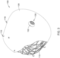
- Figures 3 and 3A illustrate an example medical implant 100 having a frame 110 configured to actuate between a collapsed configuration and an expanded configuration.
- the example medical implant 100 may include an occlusive element 120 disposed on, disposed over, disposed about, or covering at least a portion of the frame 110.
- the occlusive element 120 may be disposed on, disposed over, disposed about or cover at least a portion of an outer (or outwardly-facing) surface of the frame 110.
- a proximal end of the frame 110 may form a generally tubular portion 112, the generally tubular portion 112 being configured to attach to or couple to a distal end of a core wire 30.
- the generally tubular portion 112 of the frame 110 may include a threaded insert 130 coupled thereto.
- the threaded insert 130 may be at least partially disposed within the generally tubular portion 112 of the frame 110.
- the threaded insert 130 may be configured to and/or adapted to couple with, join to, mate with, or otherwise engage a threaded member 36 disposed at the distal end 32 of the core wire 30.
- a first portion of the occlusive element 120 may be disposed between the threaded insert 130 and the generally tubular portion 112. In some embodiments, the first portion of the occlusive element 120 may be pinched or held between the threaded insert 130 and the generally tubular portion 112.
- the threaded insert 130 may include a curved or angled proximally-facing surface 132 that extends radially outward from threads formed within a center of the threaded insert 130. In some embodiments, the curved or angled proximally-facing surface 132 may extend proximally of the occlusive element 120 in the expanded configuration and/or the collapsed configuration.
- the curved or angled proximally-facing surface 132 may have an outer extent that is disposed radially outward from the first portion of the occlusive element 120 and/or the generally tubular portion 112.
- the frame 110 may include a plurality of proximally-facing hooks 118 disposed about a periphery of the frame 110 in the expanded configuration.
- the plurality of proximally-facing hooks 118 may provide an anchoring mechanism to aid in retaining a deployed medical implant 100 at a target site within a patient's anatomy (i.e., the left atrial appendage, for example).
- Figures 4 and 4A illustrate an example medical implant 200 having a frame 210 configured to actuate between a collapsed configuration and an expanded configuration.
- the example medical implant 200 may include an occlusive element 220 disposed on, disposed over, disposed about, or covering at least a portion of the frame 210.
- the occlusive element 220 may be disposed on, disposed over, disposed about or cover at least a portion of an outer (or outwardly-facing) surface of the frame 210.
- a proximal end of the frame 210 may form a generally tubular portion 212, the generally tubular portion 212 being configured to attach to or couple to a distal end 32 of a core wire 30.
- the generally tubular portion 212 of the frame 210 may include a threaded insert 230 coupled thereto.
- the frame 210 may include an annular collar member 240 at least partially disposed within the generally tubular portion 212 and coupled thereto.
- the threaded insert 230 may be coupled to the annular collar member 240.
- the threaded insert 230 may be at least partially disposed within the annular collar member 240.
- a pin element 250 may couple the annular collar member 240 and/or the threaded insert 230 to the frame 210 and/or to each other.
- the annular collar member 240 and/or threaded insert 230 may be fixedly attached to and/or coupled with the generally tubular portion 212 of the frame 210 and/or each other. In some embodiments, the annular collar member 240 and/or threaded insert 230 may be permanently attached to and/or coupled with the generally tubular portion 212 of the frame 210 and/or each other. In some embodiments, the annular collar member 240 and/or threaded insert 230 may be removably attached to and/or coupled with the generally tubular portion 212 of the frame 210 and/or each other.
- the threaded insert 230 may be configured to and/or adapted to reversibly and/or removably couple with, join to, mate with, or otherwise engage a threaded member 36 disposed at the distal end 32 of the core wire 30.
- a first portion of the occlusive element 220 may be disposed between the threaded insert 230 and the annular collar member 240. In some embodiments, the first portion of the occlusive element 220 may be pinched or held between the threaded insert 230 and the annular collar member 240. In some embodiments, the threaded insert 230 may be disposed distally of a portion of the occlusive element 220 disposed outside of the annular collar member 240 in the expanded configuration and/or the collapsed configuration. In some embodiments, an outer portion of the occlusive element 220 may be defined as that part of the occlusive element 220 disposed outside of the annular collar member 240.
- the outer portion of the occlusive element 220 may be disposed radially outward from the threaded insert 230 in the expanded configuration.
- the frame 210 may include a plurality of proximally-facing hooks 218 disposed about a periphery of the frame 210 in the expanded configuration.
- the plurality of proximally-facing hooks 218 may provide an anchoring mechanism to aid in retaining a deployed medical implant 200 at a target site within a patient's anatomy (i.e., the left atrial appendage, for example).
- the medical implant 200 of Figure 4 may have a reduced amount of exposed material (i.e., metallic material) at the threaded insert compared to the medical implant 100 of Figure 3 .
- exposed material i.e., metallic material
- Applicants have found that reducing the amount of metallic material exposed to the bloodstream may provide certain advantages such as reduced thrombus formation and/or more rapid endothelization.
- a core wire 30 may have a maximum outer diameter that is considerably smaller than a minimum inner diameter of a lumen 42 of a delivery catheter 40.
- the inner diameter of the lumen 42 of the delivery catheter 40 may be sized to accommodate a medical implant 20 within the lumen 42 in a collapsed configuration.
- the outer diameter of the core wire 30 may be sized to provide sufficient flexibility to the core wire 30 and the delivery assembly and/or implant system 10 for navigation through a patient's vasculature to a target site (i.e., the left atrial appendage, for example) while maintaining a desired level of torquability and/or pushability.
- the difference in size between the core wire 30 and the lumen 42 may allow a significant amount of "play", or lateral movement relative to a central axis of the lumen 42, between the core wire 30 and the delivery catheter 40.
- a medical implant 20 and/or the distal end 32 of the core wire 30 may become misaligned with the lumen 42 of the delivery catheter 40 after being extended distally from the lumen 42, such as during deployment of the medical implant 20 and/or during removal or recapture of the medical implant 20.
- a practitioner may recapture the medical implant 20 and deploy it again to ensure proper placement.
- the surrounding tissue i.e., the ostium of the left atrial appendage, for example
- a practitioner may recapture the medical implant 20 and deploy it again to ensure proper placement.
- it may be necessary at some point to remove the medical implant after deployment and release within a patient's anatomy.
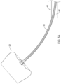
- a distal end 44 of the delivery catheter 40 may come into contact with the medical implant 20 and/or the occlusive element disposed thereon, as seen in Figure 6 .
- the forces required to actuate the frame from the expanded configuration to the collapsed configuration may be increased, and in some cases high enough to result in tearing of, or damage to, the occlusive element as the occlusive element is pinched between the frame and the delivery catheter 40, thereby requiring full removal from patient and replacement of the implant 20 before the procedure may proceed. Accordingly, a feature which may result in centering of the implant 20 within the lumen 42 may be beneficial in at least some circumstances.
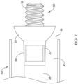
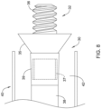
- Figures 7-9 illustrate an example core wire 30 having a threaded member 36 at a distal end 32.
- the threaded member 36 may be configured and/or adapted to engage, attach to, connect to, and/or mate with a threaded insert of an example medical implant 20.
- the example core wire 30 may include a guide element 35 disposed about the core wire 30 adjacent a proximal end of the threaded member 36.
- the guide element 35 may be shaped and/or configured to center the core wire 30 and/or the medical implant 20 within the lumen 42 of the delivery catheter 40.
- the guide element 35 may include a curved, convex proximal surface and a generally flat distal surface, as shown in Figure 7 , for example.
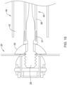
- the guide element 35 may include a conical proximal surface and a generally flat distal surface, as shown in Figure 8 , for example. In some embodiments, the guide element 35 may include a generally rounded, bulbous, convex outer surface, as shown in Figure 9 , for example. In some embodiments, a distal surface of the guide element 35 may be configured to and/or adapted to contact or engage the medical implant 20 when the threaded member 36 is engaged with, attached to, connected to, and/or mated with the threaded insert, as seen for example in Figures 10-11 .
- a distal surface of the guide element 35 may not contact or engage the medical implant 20 when the threaded member 36 is engaged with, attached to, connected to, and/or mated with the threaded insert, and the distal surface of the guide element 35 may be spaced apart from the medical implant 20.
- an occlusive implant system 10 may include a delivery catheter 40 having a lumen 42 extending therethrough, a core wire 30 slidably and/or rotatably disposed within the lumen 42, the core wire 30 having a threaded member 36 disposed at a distal end 32 thereof, and a medical implant 20 having an expandable frame, an occlusive element disposed on the frame, and a threaded insert coupled to a proximal portion of the frame, wherein the threaded member 36 may be removably coupled to the threaded insert, as shown for example in Figures 10-11 .
- the example core wire 30 is shown attached to the example medical implant 200 described herein.
- the example core wire 30 may also be used with the example medical implant 100 described herein or other similar medical implants/devices.
- the frame may be actuatable between a collapsed configuration and an expanded configuration.
- the frame may be self-expanding.
- the frame may be manually actuatable from the collapsed configuration to the expanded configuration.
- a portion of the occlusive element may be disposed between the threaded insert and the proximal portion of the frame.
- a portion of the occlusive element may extend proximally of the threaded insert.
- the medical implant 20 may include an annular collar member disposed between the proximal portion of the frame and the threaded insert.
- the annular collar member and/or the threaded insert may be removably and/or reversibly coupled to, attached to, connected to, and/or engaged with the proximal portion of the frame by a pin element.
- the annular collar member and/or the threaded insert may be fixedly and/or permanently coupled to, attached to, connected to, and/or engaged with the proximal portion of the frame, such as by adhesion, welding, mechanical fastening, and the like.
- the core wire 30 may include a guide element 35 disposed adjacent a proximal end of the threaded member 36.
- the guide element 35 may be configured and/or adapted to center the core wire 30 within the lumen 42 of the delivery catheter 40.
- the guide element 35 may be slidably disposed about the core wire 30.
- the guide element 35 may be positioned against the threaded member 36 and axially retained in place by a polymeric jacket 38 disposed over and/or on the core wire 30 and in contact with the guide element 35 at a distal end of the polymeric jacket 38.
- the guide element 35 may be fixedly and/or permanently attached to the core wire 30, such as by adhesion, welding, mechanical fastening, and the like. In some embodiments, the guide element 35 may be integrally formed with the core wire 30 as a monolithic unit. In some embodiments, a marker band 37 may be disposed about the core wire 30 adjacent the guide element 35. In some embodiments, the marker band 37 may be disposed over the polymeric jacket 38 and may crimp a distal portion of the polymeric jacket 38 covering the core wire 30 onto the core wire 30. In some embodiments, a discrete piece of polymeric material 39 may be disposed over the marker band 37, as seen for example in Figures 7-9 .
- the discrete piece of material 39 may be heated and/or joined to the polymeric jacket 38, such as by reflow, for example, to form a single polymeric cover member.
- the marker band 37 may be at least partially encapsulated by the polymeric jacket 38, the discrete piece of polymeric material 39, and/or the polymeric cover member.
- the discrete piece of polymeric material 39 may form the guide element 35, as seen for example in Figure 9 .
- a core wire 30 may include a stepped outer diameter and/or a narrowed distal section adjacent a threaded member 36 disposed at the distal end 32, as may be seen in Figures 10-11 .
- a polymeric jacket 38 disposed over and/or on the core wire 30 may be formed, crimped, or otherwise forced into place over the narrowed distal section, resulting in a portion of the polymeric jacket 38 being mechanically locked into place and preventing the polymeric jacket 38 from sliding proximally relative to the core wire 30.
- the marker band 37 may mechanically lock the polymeric jacket 38 in place relative to the core wire 30. The mechanical locking may occur with or without the guide element 35 disposed adjacent the threaded member 36.
- a method of making a centering core wire may include some or all of the steps of:
- the marker band 37 may be at least partially encapsulated by reflow of the polymeric jacket 38 and the piece of polymeric material 39.
- the marker band 37 may be at least partially encapsulated by the polymeric cover member formed by reflow of the polymeric jacket 38 and the piece of polymeric material 39.
- the elongate core wire 30 may include a stepped outer diameter and/or a narrowed section adjacent the threaded member 36 for providing a mechanical interlock between the core wire 30 and the polymeric jacket 38.
- Figures 3 and 4 illustrate an example medical implant having a membrane or occlusive element disposed over at least a portion of the frame.
- at least some of the plurality of proximally-facing hooks project through the membrane or occlusive element.
- the membrane or occlusive element may be attached to the frame at each proximally-facing hook, for example, by passing each proximally-facing hook through the membrane or occlusive element, such as through a pore or aperture.
- the membrane or occlusive element may be attached to the frame by other suitable attachment means, such as but not limited to, adhesive(s), sutures or thread(s), welding or soldering, or combinations thereof.
- the membrane or occlusive element may be permeable or impermeable to blood and/or other fluids, such as water.
- the membrane or occlusive element may include a polymeric membrane, a metallic or polymeric mesh, a porous filter-like material, or other suitable construction.
- the membrane or occlusive element prevents thrombi (i.e. blood clots, etc.) from passing through the membrane or occlusive element and out of the left atrial appendage into the blood stream.
- the membrane or occlusive element promotes endothelization after implantation, thereby effectively removing the left atrial appendage from the patient's circulatory system.
- the frame may be compliant and substantially conform to and/or be in sealing engagement with the shape and/or geometry of a lateral wall of a left atrial appendage in the expanded configuration.
- the medical implant may expand to a size, extent, or shape less than or different from a maximum unconstrained extent, as determined by the surrounding tissue and/or lateral wall of the left atrial appendage. Reducing the thickness of the plurality of struts may increase the flexibility and compliance of the support frame and/or the implant, thereby permitting the implant to conform to the tissue around it, rather than forcing the tissue to conform to the implant.
- the plurality of struts of the frame, the plurality of proximally-facing hooks, and/or the core wire may be formed of or include a metallic material, a metallic alloy, a ceramic material, a rigid or high performance polymer, a metallic-polymer composite, combinations thereof, and the like.
- suitable materials may include metallic materials and/or alloys such as stainless steel (e.g., 303, 304v, or 316L stainless steel), nickel-titanium alloy (e.g., nitinol, such as super elastic or linear elastic nitinol), nickel-chromium alloy, nickel-chromium-iron alloy, cobalt alloy, nickel, titanium, platinum, or alternatively, a polymer material, such as a high performance polymer, or other suitable materials, and the like.
- nitinol was coined by a group of researchers at the United States Naval Ordinance Laboratory (NOL) who were the first to observe the shape memory behavior of this material.
- NOL United States Naval Ordinance Laboratory
- the word nitinol is an acronym including the chemical symbol for nickel (Ni), the chemical symbol for titanium (Ti), and an acronym identifying the Naval Ordinance Laboratory (NOL).
- the plurality of struts of the frame, the plurality of proximally-facing hooks, and/or the marker band may be mixed with, may be doped with, may be coated with, or may otherwise include a radiopaque material.
- Radiopaque materials are understood to be materials capable of producing a relatively bright image on a fluoroscopy screen or another imaging technique such as X-ray during a medical procedure. This relatively bright image aids the user of device in determining its location.
- Suitable radiopaque materials may include, but are not limited to, bismuth subcarbonate, iodine, gold, platinum, palladium, tantalum, tungsten or tungsten alloy, and the like.
- the membrane or occlusive element may be formed of or include a polymeric material, a metallic or metallic alloy material, a metallic-polymer composite, combinations thereof, and the like.
- the membrane or occlusive element is preferably formed of polyethylene terephthalate (PET) such as DACRON ® , or expanded polytetrafluoroethylene (ePTFE).
- suitable polymers may include polyurethane, a polyether-ester such as ARNITEL ® available from DSM Engineering Plastics, a polyester such as HYTREL ® available from DuPont, a linear low density polyethylene such as REXELL ® , a polyamide such as DURETHAN ® available from Bayer or CRISTAMID ® available from Elf Atochem, an elastomeric polyamide, a block polyamide/ether, a polyether block amide such as PEBA available under the trade name PEBAX ® , silicones, polyethylene, Marlex high-density polyethylene, polytetrafluoroethylene (PTFE), polyetheretherketone (PEEK), polyimide (PI), and polyetherimide (PEI), a liquid crystal polymer (LCP) alone or blended with other materials.
- a polyether-ester such as ARNITEL ® available from DSM Engineering Plastics
- HYTREL ® available from DuPont
- a linear low density polyethylene
- the delivery catheter and/or the medical implant may be made from, may be mixed with, may be coated with, or may otherwise include a material that provides a smooth, slippery outer surface.
- the delivery catheter and/or the medical implant may include or be coated with a lubricious coating, a hydrophilic coating, a hydrophobic coating, a drug-eluting material, an anti-thrombus coating, or other suitable coating depending on the intended use or application.
- devices and methods in accordance with the disclosure can be adapted and configured for use in other parts of the anatomy of a patient.
- devices and methods in accordance with the disclosure can be adapted for use in the digestive or gastrointestinal tract, such as in the mouth, throat, small and large intestine, colon, rectum, and the like.
- devices and methods can be adapted and configured for use within the respiratory tract, such as in the mouth, nose, throat, bronchial passages, nasal passages, lungs, and the like.
- the apparatus and/or medical devices described herein with respect to percutaneous deployment may be used in other types of surgical procedures as appropriate.
- the medical devices may be deployed in a non-percutaneous procedure, such as an open heart procedure.
- Devices and methods in accordance with the invention can also be adapted and configured for other uses within the anatomy.
Landscapes
- Health & Medical Sciences (AREA)
- Surgery (AREA)
- Life Sciences & Earth Sciences (AREA)
- Biomedical Technology (AREA)
- Medical Informatics (AREA)
- Veterinary Medicine (AREA)
- Public Health (AREA)
- Engineering & Computer Science (AREA)
- General Health & Medical Sciences (AREA)
- Heart & Thoracic Surgery (AREA)
- Nuclear Medicine, Radiotherapy & Molecular Imaging (AREA)
- Molecular Biology (AREA)
- Animal Behavior & Ethology (AREA)
- Reproductive Health (AREA)
- Vascular Medicine (AREA)
- Cardiology (AREA)
- Surgical Instruments (AREA)
- Prostheses (AREA)
Abstract
Description
- The disclosure relates generally to percutaneous medical devices and more particularly to percutaneous medical devices for implantation into the left atrial appendage (LAA) of a heart.
- Atrial fibrillation (AF) is the most common sustained cardiac arrhythmia, affecting over 5.5 million people worldwide. Atrial fibrillation is the irregular, chaotic beating of the upper chambers of the heart. Electrical impulses discharge so rapidly that the atrial muscle quivers, or fibrillates. Episodes of atrial fibrillation may last a few minutes or several days. The most serious consequence of atrial fibrillation is ischemic stroke. It has been estimated that up to 20% of all strokes are related to atrial fibrillation. Most atrial fibrillation patients, regardless of the severity of their symptoms or frequency of episodes, require treatment to reduce the risk of stroke. The left atrial appendage (LAA) is a small organ attached to the left atrium of the heart as a pouch-like extension. In patients suffering from atrial fibrillation, the left atrial appendage may not properly contract with the left atrium, causing stagnant blood to pool within its interior, which can lead to the undesirable formation of thrombi within the left atrial appendage. Thrombi forming in the left atrial appendage may break loose from this area and enter the blood stream. Thrombi that migrate through the blood vessels may eventually plug a smaller vessel downstream and thereby contribute to stroke or heart attack. Clinical studies have shown that the majority of blood clots in patients with atrial fibrillation are found in the left atrial appendage. As a treatment, medical devices have been developed which are positioned in the left atrial appendage and deployed to close off the ostium of the left atrial appendage. Over time, the exposed surface(s) spanning the ostium of the left atrial appendage becomes covered with tissue (a process called endothelization), effectively removing the left atrial appendage from the circulatory system and reducing or eliminating the amount of thrombi which may enter the blood stream from the left atrial appendage.
- A continuing need exists for improved medical devices and methods to control thrombus formation within the left atrial appendage of patients suffering from atrial fibrillation.
- A medical implant may include a frame configured to actuate between a collapsed configuration and an expanded configuration, and an occlusive element covering at least a portion of the frame, wherein a proximal end of the frame forms a generally tubular portion, the tubular portion being configured to attach to a distal end of a core wire, and wherein the tubular portion of the frame includes a threaded insert coupled thereto.
- An occlusive implant system may include a catheter having a lumen extending therethrough, a core wire slidably and rotatably disposed within the lumen, the core wire having a threaded member disposed at a distal end thereof, and a medical implant having an expandable frame, an occlusive element disposed on the frame, and a threaded insert coupled to a proximal portion of the frame, wherein the threaded member is removably coupled to the threaded insert.
- A method of making a centering core wire may include obtaining an elongate core wire having a threaded member disposed at a distal end thereof; obtaining a guide element having an aperture or lumen disposed therein; inserting a proximal end of the elongate core wire into the aperture or lumen; sliding the guide element distally over the elongate core wire into contact with the threaded member; and applying a polymeric jacket over the elongate core wire from the proximal end to the guide element; wherein the polymeric jacket retains the guide element against the threaded member.
-
-
Figure 1 is a side view of an example medical implant and delivery assembly; -
Figure 2 is a partial cross-sectional view of an example medical implant disposed within a delivery assembly; -
Figure 3 is a perspective view of an example medical implant; -
Figure 3A is a partial cross-sectional view of the example medical implant ofFigure 3 ; -
Figure 4 is a perspective view of an example medical implant; -
Figure 4A is a partial cross-sectional view of the example medical implant ofFigure 4 ; -
Figures 5A and5B illustrate the extent of relative movement between certain elements of the delivery assembly ofFigure 1 ; -
Figure 6 is a partial cross-sectional view of an example medical implant being retracted into a delivery catheter; -
Figure 7 is a side view of an example guide element; -
Figure 8 is a side view of an example guide element; -
Figure 9 is a side view of an example guide element; -
Figure 10 is a side view of an example medical implant connected to an example core wire having the example guide element ofFigure 7 ; -
Figure 10A is a side view of the example medical implant ofFigure 10 misaligned with an example delivery catheter lumen; and -
Figure 11 is a side view of the example medical implant ofFigure 10 being centered with an example delivery catheter lumen. - While the invention is amenable to various modifications and alternative forms, specifics thereof have been shown by way of example in the drawings and will be described in greater detail below. It should be understood, however, that the intention is not to limit the invention to the particular embodiments described. On the contrary, the intention is to cover all modifications, equivalents, and alternatives falling within the spirit and scope of the invention.
- For the following defined terms, these definitions shall be applied, unless a different definition is given in the claims or elsewhere in this specification.
- The terms "upstream" and "downstream" refer to a position or location relative to the direction of blood flow through a particular element or location, such as a vessel (i.e., the aorta), a heart valve (i.e., the aortic valve), and the like.
- The terms "proximal" and "distal" shall generally refer to the relative position, orientation, or direction of an element or action, from the perspective of a clinician using the medical device, relative to one another. While the terms are not meant to be limiting, "proximal" may generally be considered closer to the clinician or an exterior of a patient, and "distal" may generally be considered to be farther away from the clinician, along the length of the medical device.
- The terms "monolithic" and "unitary" shall generally refer to an element or elements made from or consisting of a single structure or base unit/element. A monolithic and/or unitary element shall exclude structure and/or features made by assembling or otherwise joining multiple discrete elements together.
- All numeric values are herein assumed to be modified by the term "about," whether or not explicitly indicated. The term "about", in the context of numeric values, generally refers to a range of numbers that one of skill in the art would consider equivalent to the recited value (i.e., having the same function or result). In many instances, the term "about" may include numbers that are rounded to the nearest significant figure. Other uses of the term "about" (i.e., in a context other than numeric values) may be assumed to have their ordinary and customary definition(s), as understood from and consistent with the context of the specification, unless otherwise specified.
- Weight percent, percent by weight, wt%, wt-%, % by weight, and the like are synonyms that refer to the concentration of a substance as the weight of that substance divided by the weight of the composition and multiplied by 100.
- The recitation of numerical ranges by endpoints includes all numbers within that range, including the endpoints (e.g. 1 to 5 includes 1, 1.5, 2, 2.75, 3, 3.80, 4, and 5).
- As used in this specification and the appended claims, the singular forms "a", "an", and "the" include plural referents unless the content clearly dictates otherwise. As used in this specification and the appended claims, the term "or" is generally employed in its sense including "and/or" unless the content clearly dictates otherwise.
- The following description should be read with reference to the drawings wherein like reference numerals indicate like elements throughout the several views. The detailed description and drawings are intended to illustrate but not limit the claimed invention. Those skilled in the art will recognize that the various elements described and/or shown may be arranged in various combinations and configurations without departing from the scope of the disclosure. The various individual elements described below, even if not explicitly shown in a particular combination, are nevertheless contemplated as being combinable or arrangable with each other to form other additional embodiments or to complement and/or enrich the described embodiment(s), as would be understood by one of ordinary skill in the art.
- The occurrence of thrombi in the left atrial appendage (LAA) during atrial fibrillation may be due to stagnancy of the blood pool in the LAA. The blood may still be pulled out of the left atrium by the left ventricle, however less effectively due to the irregular contraction of the left atrium caused by atrial fibrillation. Therefore, instead of an active support of the blood flow by a contracting left atrium and left atrial appendage, filling of the left ventricle may depend primarily or solely on the suction effect created by the left ventricle. Further, the contraction of the left atrial appendage may not be in sync with the cycle of the left ventricle. For example, contraction of the left atrial appendage may be out of phase up to 180 degrees with the left ventricle, which may create significant resistance to the desired flow of blood. Further still, most left atrial appendage geometries are complex and highly variable, with large irregular surface areas and a narrow ostium or opening compared to the depth of the left atrial appendage. These aspects as well as others, taken individually or in various combinations, may lead to high flow resistance of blood out of the left atrial appendage.
- In an effort to reduce the occurrence of thrombi formation within the left atrial appendage and prevent thrombi from entering the blood stream from within the left atrial appendage, medical devices have been developed that close off the left atrial appendage from the heart and/or circulatory system, thereby lowering the risk of stroke due to thrombolytic material entering the blood stream from the left atrial appendage. Difficulties encountered during placement of said medical device(s) may occasionally require removal and/or recapture procedures. In an effort to ease recapture procedures and/or to provide a medical device suitable for long term implantation, favorable new features have been developed.
- Turning now to the figures,
Figure 1 illustrates an example delivery assembly and/orimplant system 10 including an examplemedical implant 20 disposed at adistal end 32 of anexample core wire 30. Thecore wire 30 may be slidably and/or rotatably disposed within alumen 42 of adelivery catheter 40. In some embodiments, aproximal end 34 of thecore wire 30 may extend proximally of a proximal end of thedelivery catheter 40 for manual manipulation by a clinician or practitioner. In some embodiments, the examplemedical implant 20 may be removably attached, joined, or otherwise connected to thedistal end 32 of theexample core wire 30. An examplemedical implant 20 may be configured to actuate from a collapsed configuration to an expanded configuration when (or after being) extended distally from thedelivery catheter 40, as seen inFigure 1 for example.Figure 2 illustrates the examplemedical implant 20 disposed within a distal portion of thelumen 42 of thedelivery catheter 40 in the collapsed configuration. It is contemplated that any and/or all example medical implants disclosed herein may be used in accordance with and/or be associated with the example delivery assembly and/orimplant system 10 described above. -
Figures 3 and3A illustrate an examplemedical implant 100 having aframe 110 configured to actuate between a collapsed configuration and an expanded configuration. In some embodiments, the examplemedical implant 100 may include anocclusive element 120 disposed on, disposed over, disposed about, or covering at least a portion of theframe 110. In some embodiments, theocclusive element 120 may be disposed on, disposed over, disposed about or cover at least a portion of an outer (or outwardly-facing) surface of theframe 110. In some embodiments, a proximal end of theframe 110 may form a generallytubular portion 112, the generallytubular portion 112 being configured to attach to or couple to a distal end of acore wire 30. In some embodiments, the generallytubular portion 112 of theframe 110 may include a threadedinsert 130 coupled thereto. In some embodiments, the threadedinsert 130 may be at least partially disposed within the generallytubular portion 112 of theframe 110. In some embodiments, the threadedinsert 130 may be configured to and/or adapted to couple with, join to, mate with, or otherwise engage a threadedmember 36 disposed at thedistal end 32 of thecore wire 30. - In some embodiments, a first portion of the
occlusive element 120 may be disposed between the threadedinsert 130 and the generallytubular portion 112. In some embodiments, the first portion of theocclusive element 120 may be pinched or held between the threadedinsert 130 and the generallytubular portion 112. In some embodiments, the threadedinsert 130 may include a curved or angled proximally-facingsurface 132 that extends radially outward from threads formed within a center of the threadedinsert 130. In some embodiments, the curved or angled proximally-facingsurface 132 may extend proximally of theocclusive element 120 in the expanded configuration and/or the collapsed configuration. In some embodiments, the curved or angled proximally-facingsurface 132 may have an outer extent that is disposed radially outward from the first portion of theocclusive element 120 and/or the generallytubular portion 112. In some embodiments, theframe 110 may include a plurality of proximally-facinghooks 118 disposed about a periphery of theframe 110 in the expanded configuration. In some embodiments, the plurality of proximally-facinghooks 118 may provide an anchoring mechanism to aid in retaining a deployedmedical implant 100 at a target site within a patient's anatomy (i.e., the left atrial appendage, for example). -
Figures 4 and4A illustrate an examplemedical implant 200 having aframe 210 configured to actuate between a collapsed configuration and an expanded configuration. In some embodiments, the examplemedical implant 200 may include anocclusive element 220 disposed on, disposed over, disposed about, or covering at least a portion of theframe 210. In some embodiments, theocclusive element 220 may be disposed on, disposed over, disposed about or cover at least a portion of an outer (or outwardly-facing) surface of theframe 210. In some embodiments, a proximal end of theframe 210 may form a generallytubular portion 212, the generallytubular portion 212 being configured to attach to or couple to adistal end 32 of acore wire 30. In some embodiments, the generallytubular portion 212 of theframe 210 may include a threadedinsert 230 coupled thereto. In some embodiments, theframe 210 may include anannular collar member 240 at least partially disposed within the generallytubular portion 212 and coupled thereto. In some embodiments, the threadedinsert 230 may be coupled to theannular collar member 240. In some embodiments, the threadedinsert 230 may be at least partially disposed within theannular collar member 240. In some embodiments, apin element 250 may couple theannular collar member 240 and/or the threadedinsert 230 to theframe 210 and/or to each other. In some embodiments, theannular collar member 240 and/or threadedinsert 230 may be fixedly attached to and/or coupled with the generallytubular portion 212 of theframe 210 and/or each other. In some embodiments, theannular collar member 240 and/or threadedinsert 230 may be permanently attached to and/or coupled with the generallytubular portion 212 of theframe 210 and/or each other. In some embodiments, theannular collar member 240 and/or threadedinsert 230 may be removably attached to and/or coupled with the generallytubular portion 212 of theframe 210 and/or each other. In some embodiments, the threadedinsert 230 may be configured to and/or adapted to reversibly and/or removably couple with, join to, mate with, or otherwise engage a threadedmember 36 disposed at thedistal end 32 of thecore wire 30. - In some embodiments, a first portion of the
occlusive element 220 may be disposed between the threadedinsert 230 and theannular collar member 240. In some embodiments, the first portion of theocclusive element 220 may be pinched or held between the threadedinsert 230 and theannular collar member 240. In some embodiments, the threadedinsert 230 may be disposed distally of a portion of theocclusive element 220 disposed outside of theannular collar member 240 in the expanded configuration and/or the collapsed configuration. In some embodiments, an outer portion of theocclusive element 220 may be defined as that part of theocclusive element 220 disposed outside of theannular collar member 240. In some embodiments, the outer portion of theocclusive element 220 may be disposed radially outward from the threadedinsert 230 in the expanded configuration. In some embodiments, theframe 210 may include a plurality of proximally-facinghooks 218 disposed about a periphery of theframe 210 in the expanded configuration. In some embodiments, the plurality of proximally-facinghooks 218 may provide an anchoring mechanism to aid in retaining a deployedmedical implant 200 at a target site within a patient's anatomy (i.e., the left atrial appendage, for example). - In some embodiments, the
medical implant 200 ofFigure 4 may have a reduced amount of exposed material (i.e., metallic material) at the threaded insert compared to themedical implant 100 ofFigure 3 . Applicants have found that reducing the amount of metallic material exposed to the bloodstream may provide certain advantages such as reduced thrombus formation and/or more rapid endothelization. - As illustrated in
Figures 5A and5B , in some embodiments, acore wire 30 may have a maximum outer diameter that is considerably smaller than a minimum inner diameter of alumen 42 of adelivery catheter 40. The inner diameter of thelumen 42 of thedelivery catheter 40 may be sized to accommodate amedical implant 20 within thelumen 42 in a collapsed configuration. The outer diameter of thecore wire 30 may be sized to provide sufficient flexibility to thecore wire 30 and the delivery assembly and/orimplant system 10 for navigation through a patient's vasculature to a target site (i.e., the left atrial appendage, for example) while maintaining a desired level of torquability and/or pushability. - As may be seen in
Figures 5A and5B , the difference in size between thecore wire 30 and thelumen 42 may allow a significant amount of "play", or lateral movement relative to a central axis of thelumen 42, between thecore wire 30 and thedelivery catheter 40. As such, amedical implant 20 and/or thedistal end 32 of thecore wire 30 may become misaligned with thelumen 42 of thedelivery catheter 40 after being extended distally from thelumen 42, such as during deployment of themedical implant 20 and/or during removal or recapture of themedical implant 20. During some procedures, it may be necessary to withdraw and/or recapture themedical implant 20 after initial placement, prior to releasing themedical implant 20 from thecore wire 30. For example, if an inadequate seal is achieved between themedical implant 20 and the surrounding tissue (i.e., the ostium of the left atrial appendage, for example), a practitioner may recapture themedical implant 20 and deploy it again to ensure proper placement. Alternatively, it may be necessary at some point to remove the medical implant after deployment and release within a patient's anatomy. During recapture procedures, a distal end 44 of thedelivery catheter 40 may come into contact with themedical implant 20 and/or the occlusive element disposed thereon, as seen inFigure 6 . If themedical implant 20 is not generally centered within the distal opening of thelumen 42, the forces required to actuate the frame from the expanded configuration to the collapsed configuration may be increased, and in some cases high enough to result in tearing of, or damage to, the occlusive element as the occlusive element is pinched between the frame and thedelivery catheter 40, thereby requiring full removal from patient and replacement of theimplant 20 before the procedure may proceed. Accordingly, a feature which may result in centering of theimplant 20 within thelumen 42 may be beneficial in at least some circumstances. -
Figures 7-9 illustrate anexample core wire 30 having a threadedmember 36 at adistal end 32. In some embodiments, the threadedmember 36 may be configured and/or adapted to engage, attach to, connect to, and/or mate with a threaded insert of an examplemedical implant 20. Theexample core wire 30 may include aguide element 35 disposed about thecore wire 30 adjacent a proximal end of the threadedmember 36. Theguide element 35 may be shaped and/or configured to center thecore wire 30 and/or themedical implant 20 within thelumen 42 of thedelivery catheter 40. In some embodiments, theguide element 35 may include a curved, convex proximal surface and a generally flat distal surface, as shown inFigure 7 , for example. In some embodiments, theguide element 35 may include a conical proximal surface and a generally flat distal surface, as shown inFigure 8 , for example. In some embodiments, theguide element 35 may include a generally rounded, bulbous, convex outer surface, as shown inFigure 9 , for example. In some embodiments, a distal surface of theguide element 35 may be configured to and/or adapted to contact or engage themedical implant 20 when the threadedmember 36 is engaged with, attached to, connected to, and/or mated with the threaded insert, as seen for example inFigures 10-11 . In some embodiments, a distal surface of theguide element 35 may not contact or engage themedical implant 20 when the threadedmember 36 is engaged with, attached to, connected to, and/or mated with the threaded insert, and the distal surface of theguide element 35 may be spaced apart from themedical implant 20. - In some embodiments, an
occlusive implant system 10 may include adelivery catheter 40 having alumen 42 extending therethrough, acore wire 30 slidably and/or rotatably disposed within thelumen 42, thecore wire 30 having a threadedmember 36 disposed at adistal end 32 thereof, and amedical implant 20 having an expandable frame, an occlusive element disposed on the frame, and a threaded insert coupled to a proximal portion of the frame, wherein the threadedmember 36 may be removably coupled to the threaded insert, as shown for example inFigures 10-11 . In the exemplary figures provided herewith, theexample core wire 30 is shown attached to the examplemedical implant 200 described herein. However, theexample core wire 30 may also be used with the examplemedical implant 100 described herein or other similar medical implants/devices. In some embodiments, the frame may be actuatable between a collapsed configuration and an expanded configuration. In some embodiments, the frame may be self-expanding. In some embodiments, the frame may be manually actuatable from the collapsed configuration to the expanded configuration. In some embodiments, a portion of the occlusive element may be disposed between the threaded insert and the proximal portion of the frame. In some embodiments, a portion of the occlusive element may extend proximally of the threaded insert. In some embodiments, themedical implant 20 may include an annular collar member disposed between the proximal portion of the frame and the threaded insert. In some embodiments, the annular collar member and/or the threaded insert may be removably and/or reversibly coupled to, attached to, connected to, and/or engaged with the proximal portion of the frame by a pin element. In some embodiments, the annular collar member and/or the threaded insert may be fixedly and/or permanently coupled to, attached to, connected to, and/or engaged with the proximal portion of the frame, such as by adhesion, welding, mechanical fastening, and the like. - In some embodiments the
core wire 30 may include aguide element 35 disposed adjacent a proximal end of the threadedmember 36. In some embodiments, theguide element 35 may be configured and/or adapted to center thecore wire 30 within thelumen 42 of thedelivery catheter 40. In some embodiments, theguide element 35 may be slidably disposed about thecore wire 30. In some embodiments, theguide element 35 may be positioned against the threadedmember 36 and axially retained in place by apolymeric jacket 38 disposed over and/or on thecore wire 30 and in contact with theguide element 35 at a distal end of thepolymeric jacket 38. In some embodiments, theguide element 35 may be fixedly and/or permanently attached to thecore wire 30, such as by adhesion, welding, mechanical fastening, and the like. In some embodiments, theguide element 35 may be integrally formed with thecore wire 30 as a monolithic unit. In some embodiments, amarker band 37 may be disposed about thecore wire 30 adjacent theguide element 35. In some embodiments, themarker band 37 may be disposed over thepolymeric jacket 38 and may crimp a distal portion of thepolymeric jacket 38 covering thecore wire 30 onto thecore wire 30. In some embodiments, a discrete piece of polymeric material 39 may be disposed over themarker band 37, as seen for example inFigures 7-9 . In some embodiments, the discrete piece of material 39 may be heated and/or joined to thepolymeric jacket 38, such as by reflow, for example, to form a single polymeric cover member. In some embodiments, themarker band 37 may be at least partially encapsulated by thepolymeric jacket 38, the discrete piece of polymeric material 39, and/or the polymeric cover member. In some embodiments, the discrete piece of polymeric material 39 may form theguide element 35, as seen for example inFigure 9 . - In some embodiments, a
core wire 30 may include a stepped outer diameter and/or a narrowed distal section adjacent a threadedmember 36 disposed at thedistal end 32, as may be seen inFigures 10-11 . Apolymeric jacket 38 disposed over and/or on thecore wire 30 may be formed, crimped, or otherwise forced into place over the narrowed distal section, resulting in a portion of thepolymeric jacket 38 being mechanically locked into place and preventing thepolymeric jacket 38 from sliding proximally relative to thecore wire 30. In some embodiments, themarker band 37 may mechanically lock thepolymeric jacket 38 in place relative to thecore wire 30. The mechanical locking may occur with or without theguide element 35 disposed adjacent the threadedmember 36. - A method of making a centering core wire may include some or all of the steps of:
- obtaining or providing an
elongate core wire 30 having a threadedmember 36 disposed at adistal end 32 thereof; - obtaining or providing a
guide element 35 having an aperture or lumen disposed therein; - inserting a
proximal end 34 of theelongate core wire 30 into the aperture of lumen, such that a proximally-facing surface of theguide element 35 provides a generally tapered, angled, or convex surface in a radially outward and distal direction from thecore wire 30; - sliding the
guide element 35 distally over theelongate core wire 30 and into contact with a proximal end of the threadedmember 36; - applying a
polymeric jacket 38 over theelongate core wire 30 from theproximal end 34 of theelongate core wire 30 to theguide element 35, wherein thepolymeric jacket 38 axially holds and/or retains theguide element 35 against the threadedmember 36; - disposing a
marker band 37 over thepolymeric jacket 38 adjacent theguide element 35; - crimping the
marker band 37 onto theelongate core wire 30 such that thepolymeric jacket 38 is fixed in position along theelongate core wire 30; - disposing a piece of polymeric material 39 about the
marker band 37; and - heating the
polymeric jacket 38 and the piece of polymeric material 39 such that thepolymeric jacket 38 and the piece of polymeric material 39 are joined together by reflow to form a polymeric cover member. - In some embodiments of the method, the
marker band 37 may be at least partially encapsulated by reflow of thepolymeric jacket 38 and the piece of polymeric material 39. In other words, themarker band 37 may be at least partially encapsulated by the polymeric cover member formed by reflow of thepolymeric jacket 38 and the piece of polymeric material 39. In some embodiments of the method, theelongate core wire 30 may include a stepped outer diameter and/or a narrowed section adjacent the threadedmember 36 for providing a mechanical interlock between thecore wire 30 and thepolymeric jacket 38. -
Figures 3 and4 illustrate an example medical implant having a membrane or occlusive element disposed over at least a portion of the frame. In some embodiments, at least some of the plurality of proximally-facing hooks project through the membrane or occlusive element. In some embodiments, the membrane or occlusive element may be attached to the frame at each proximally-facing hook, for example, by passing each proximally-facing hook through the membrane or occlusive element, such as through a pore or aperture. In some embodiments, the membrane or occlusive element may be attached to the frame by other suitable attachment means, such as but not limited to, adhesive(s), sutures or thread(s), welding or soldering, or combinations thereof. In some embodiments, the membrane or occlusive element may be permeable or impermeable to blood and/or other fluids, such as water. In some embodiments, the membrane or occlusive element may include a polymeric membrane, a metallic or polymeric mesh, a porous filter-like material, or other suitable construction. In some embodiments, the membrane or occlusive element prevents thrombi (i.e. blood clots, etc.) from passing through the membrane or occlusive element and out of the left atrial appendage into the blood stream. In some embodiments, the membrane or occlusive element promotes endothelization after implantation, thereby effectively removing the left atrial appendage from the patient's circulatory system. - The frame may be compliant and substantially conform to and/or be in sealing engagement with the shape and/or geometry of a lateral wall of a left atrial appendage in the expanded configuration. In some embodiments, the medical implant may expand to a size, extent, or shape less than or different from a maximum unconstrained extent, as determined by the surrounding tissue and/or lateral wall of the left atrial appendage. Reducing the thickness of the plurality of struts may increase the flexibility and compliance of the support frame and/or the implant, thereby permitting the implant to conform to the tissue around it, rather than forcing the tissue to conform to the implant.
- In some embodiments, the plurality of struts of the frame, the plurality of proximally-facing hooks, and/or the core wire may be formed of or include a metallic material, a metallic alloy, a ceramic material, a rigid or high performance polymer, a metallic-polymer composite, combinations thereof, and the like. Some examples of some suitable materials may include metallic materials and/or alloys such as stainless steel (e.g., 303, 304v, or 316L stainless steel), nickel-titanium alloy (e.g., nitinol, such as super elastic or linear elastic nitinol), nickel-chromium alloy, nickel-chromium-iron alloy, cobalt alloy, nickel, titanium, platinum, or alternatively, a polymer material, such as a high performance polymer, or other suitable materials, and the like. The word nitinol was coined by a group of researchers at the United States Naval Ordinance Laboratory (NOL) who were the first to observe the shape memory behavior of this material. The word nitinol is an acronym including the chemical symbol for nickel (Ni), the chemical symbol for titanium (Ti), and an acronym identifying the Naval Ordinance Laboratory (NOL).
- In some embodiments, the plurality of struts of the frame, the plurality of proximally-facing hooks, and/or the marker band may be mixed with, may be doped with, may be coated with, or may otherwise include a radiopaque material. Radiopaque materials are understood to be materials capable of producing a relatively bright image on a fluoroscopy screen or another imaging technique such as X-ray during a medical procedure. This relatively bright image aids the user of device in determining its location. Suitable radiopaque materials may include, but are not limited to, bismuth subcarbonate, iodine, gold, platinum, palladium, tantalum, tungsten or tungsten alloy, and the like.
- In some embodiments, the membrane or occlusive element may be formed of or include a polymeric material, a metallic or metallic alloy material, a metallic-polymer composite, combinations thereof, and the like. In some embodiments, the membrane or occlusive element is preferably formed of polyethylene terephthalate (PET) such as DACRON®, or expanded polytetrafluoroethylene (ePTFE). Other examples of suitable polymers may include polyurethane, a polyether-ester such as ARNITEL® available from DSM Engineering Plastics, a polyester such as HYTREL® available from DuPont, a linear low density polyethylene such as REXELL®, a polyamide such as DURETHAN® available from Bayer or CRISTAMID® available from Elf Atochem, an elastomeric polyamide, a block polyamide/ether, a polyether block amide such as PEBA available under the trade name PEBAX®, silicones, polyethylene, Marlex high-density polyethylene, polytetrafluoroethylene (PTFE), polyetheretherketone (PEEK), polyimide (PI), and polyetherimide (PEI), a liquid crystal polymer (LCP) alone or blended with other materials.
- In some embodiments, the delivery catheter and/or the medical implant may be made from, may be mixed with, may be coated with, or may otherwise include a material that provides a smooth, slippery outer surface. In some embodiments, the delivery catheter and/or the medical implant may include or be coated with a lubricious coating, a hydrophilic coating, a hydrophobic coating, a drug-eluting material, an anti-thrombus coating, or other suitable coating depending on the intended use or application.
- It should be understood that although the above discussion was focused on a medical device and methods of use within the vascular system of a patient, other embodiments of medical devices or methods in accordance with the disclosure can be adapted and configured for use in other parts of the anatomy of a patient. For example, devices and methods in accordance with the disclosure can be adapted for use in the digestive or gastrointestinal tract, such as in the mouth, throat, small and large intestine, colon, rectum, and the like. For another example, devices and methods can be adapted and configured for use within the respiratory tract, such as in the mouth, nose, throat, bronchial passages, nasal passages, lungs, and the like. Similarly, the apparatus and/or medical devices described herein with respect to percutaneous deployment may be used in other types of surgical procedures as appropriate. For example, in some embodiments, the medical devices may be deployed in a non-percutaneous procedure, such as an open heart procedure. Devices and methods in accordance with the invention can also be adapted and configured for other uses within the anatomy.
- It should be understood that this disclosure is, in many respects, only illustrative. Changes may be made in details, particularly in matters of shape, size, and arrangement of steps without exceeding the scope of the invention. The invention's scope is, of course, defined in the language in which the appended claims are expressed.
- The following aspects are preferred embodiments of the invention.
- 1. A medical implant, comprising:
- a frame configured to actuate between a collapsed configuration and an expanded configuration; and
- an occlusive element covering at least a portion of the frame;
- wherein a proximal end of the frame forms a generally tubular portion, the tubular portion being configured to attach to a distal end of a core wire;
- wherein the tubular portion of the frame includes a threaded insert coupled thereto.
- 2. The implant of
aspect 1, wherein the frame includes an annular collar member at least partially disposed within the tubular portion and coupled thereto, the threaded insert being coupled to the annular collar member. - 3. The implant of
aspect 2, wherein the threaded insert is disposed within the annular collar member. - 4. The implant of aspect 3, wherein a portion of the occlusive element is disposed between the threaded insert and the annular collar member.
- 5. The implant of
aspect 2, further including a pin element coupling the annular collar member to the frame. - 6. The implant of
aspect 1, wherein the frame includes a plurality of proximally-facing hooks disposed about a periphery of the frame in the expanded configuration. - 7. The implant of aspect 4, wherein the threaded insert is disposed distally of a portion of the occlusive element disposed outside of the annular collar member.
- 8. The implant of aspect 4, wherein an outer portion of the occlusive element is defined as that part of the occlusive element disposed outside of the annular collar member, wherein the outer portion of the occlusive element is disposed radially outward from the threaded insert in the expanded configuration.
- 9. The implant of
aspect 1, wherein the distal end of the core wire includes a threaded member configured to mate with the threaded insert. - 10. An occlusive implant system, comprising:
- a catheter having a lumen extending therethrough;
- a core wire slidably and rotatably disposed within the lumen, the core wire having a threaded member disposed at a distal end thereof; and
- a medical implant having an expandable frame, an occlusive element disposed on the frame, and a threaded insert coupled to a proximal portion of the frame;
- wherein the threaded member is removably coupled to the threaded insert.
- 11. The occlusive implant system of
aspect 10, wherein a portion of the occlusive element is disposed between the threaded insert and the proximal portion of the frame. - 12. The occlusive implant system of
aspect 10, wherein a portion of the occlusive element extends proximally of the threaded insert. - 13. The occlusive implant system of
aspect 10, wherein the core wire includes a guide element disposed adjacent a proximal end of the threaded member, the guide element being configured to center the core wire within the catheter. - 14. The occlusive implant system of aspect 13, wherein the guide element includes a convex proximal surface and a generally flat distal surface.
- 15. The occlusive implant system of aspect 13, wherein the guide element includes a conical proximal surface and a generally flat distal surface.
- 16. The occlusive implant system of aspect 13, wherein the guide element includes a generally rounded convex outer surface.
- 17. The occlusive implant system of aspect 13, wherein the guide element is disposed about the core wire.
- 18. The occlusive implant system of aspect 17, wherein the guide element is slidably disposed about the core wire.
- 19. The occlusive implant system of aspect 18, wherein the guide element is positioned against the threaded member and axially retained in place by a polymeric jacket.
- 20. The occlusive implant system of aspect 17, wherein the guide element is fixedly attached to the core wire.
- 21. The occlusive implant system of aspect 17, wherein the guide element is integrally formed with the core wire as a monolithic unit.
- 22. The occlusive implant system of aspect 13, further including a marker band disposed about the core wire adjacent the guide element, the marker band crimping a distal portion of a polymeric jacket covering the core wire onto the core wire.
- 23. The occlusive implant system of aspect 22, wherein the marker band is at least partially encapsulated by a polymeric covering member, the polymeric covering member including the polymeric jacket.
- 24. The occlusive implant system of
aspect 10, further including an annular collar member disposed between the proximal portion of the frame and the threaded insert. - 25. A method of making a centering core wire, comprising:
- obtaining an elongate core wire having a threaded member disposed at a distal end thereof;
- obtaining a guide element having an aperture or lumen disposed therein;
- inserting a proximal end of the elongate core wire into the aperture or lumen;
- sliding the guide element distally over the elongate core wire into contact with the threaded member; and
- applying a polymeric jacket over the elongate core wire from the proximal end to the guide element;
- wherein the polymeric jacket retains the guide element against the threaded member.
- 26. The method of aspect 25, further comprising:
- disposing a marker band over the polymeric jacket adjacent the guide element; and
- crimping the marker band onto the elongate core wire such that the polymeric jacket is fixed in position along the elongate core wire.
- 27. The method of aspect 26, further comprising:
- disposing a piece of polymeric material about the marker band; and
- heating the polymeric jacket and the piece of polymeric material such that the polymeric jacket and the piece of polymeric material are joined together by reflow.
- 28. The method of
aspect 27, wherein the marker band is at least partially encapsulated by a polymeric covering member formed by reflow of the polymeric jacket and the piece of polymeric material. - 29. The method of aspect 25, wherein the elongate core wire includes a stepped outer diameter adjacent the threaded member.
- 30. The method of aspect 25, wherein the elongate core wire is formed of a metallic material.
Claims (11)
- An occlusive implant system, comprising:a catheter having a lumen extending therethrough;a core wire slidably and rotatably disposed within the lumen, the core wire having a threaded member disposed at a distal end thereof; anda medical implant having an expandable frame, an occlusive element disposed on the frame, and a threaded insert coupled to a proximal portion of the frame;wherein the threaded member is removably coupled to the threaded insert.
- The occlusive implant system of claim 1, wherein a portion of the occlusive element is disposed between the threaded insert and the proximal portion of the frame.
- The occlusive implant system of claim 1, wherein a portion of the occlusive element extends proximally of the threaded insert.
- The occlusive implant system of any of claims 1 to 3, wherein the core wire includes a guide element disposed adjacent a proximal end of the threaded member, the guide element being configured to center the core wire within the catheter.
- The occlusive implant system of claim 4, wherein the guide element includes a convex proximal surface and a generally flat distal surface.
- The occlusive implant system of claim 4, wherein the guide element includes a conical proximal surface and a generally flat distal surface.
- The occlusive implant system of claim 4, wherein the guide element includes a generally rounded convex outer surface.
- The occlusive implant system of any of claims 4 to 7, wherein the guide element is disposed about the core wire.
- The occlusive implant system of claim 8, wherein the guide element is slidably disposed about the core wire.
- The occlusive implant system of claim 9, wherein the guide element is positioned against the threaded member and axially retained in place by a polymeric jacket.
- The occlusive implant system of claim 8, wherein the guide element is fixedly attached to the core wire.
Priority Applications (1)
| Application Number | Priority Date | Filing Date | Title |
|---|---|---|---|
| EP26152983.8A EP4721680A3 (en) | 2014-01-16 | 2015-01-16 | RETURN WIRE CENTERING DEVICE |
Applications Claiming Priority (4)
| Application Number | Priority Date | Filing Date | Title |
|---|---|---|---|
| US201461928260P | 2014-01-16 | 2014-01-16 | |
| US14/586,707 US9730701B2 (en) | 2014-01-16 | 2014-12-30 | Retrieval wire centering device |
| PCT/US2015/011825 WO2015109235A2 (en) | 2014-01-16 | 2015-01-16 | Retrieval wire centering device |
| EP15701929.0A EP3094263B1 (en) | 2014-01-16 | 2015-01-16 | Retrieval wire centering device |
Related Parent Applications (2)
| Application Number | Title | Priority Date | Filing Date |
|---|---|---|---|
| EP15701929.0A Division EP3094263B1 (en) | 2014-01-16 | 2015-01-16 | Retrieval wire centering device |
| EP15701929.0A Division-Into EP3094263B1 (en) | 2014-01-16 | 2015-01-16 | Retrieval wire centering device |
Related Child Applications (2)
| Application Number | Title | Priority Date | Filing Date |
|---|---|---|---|
| EP26152983.8A Division EP4721680A3 (en) | 2014-01-16 | 2015-01-16 | RETURN WIRE CENTERING DEVICE |
| EP26152983.8A Division-Into EP4721680A3 (en) | 2014-01-16 | 2015-01-16 | RETURN WIRE CENTERING DEVICE |
Publications (3)
| Publication Number | Publication Date |
|---|---|
| EP4349279A2 true EP4349279A2 (en) | 2024-04-10 |
| EP4349279A3 EP4349279A3 (en) | 2024-07-17 |
| EP4349279B1 EP4349279B1 (en) | 2026-02-25 |
Family
ID=53520316
Family Applications (3)
| Application Number | Title | Priority Date | Filing Date |
|---|---|---|---|
| EP15701929.0A Active EP3094263B1 (en) | 2014-01-16 | 2015-01-16 | Retrieval wire centering device |
| EP24152990.8A Active EP4349279B1 (en) | 2014-01-16 | 2015-01-16 | Retrieval wire centering device |
| EP26152983.8A Pending EP4721680A3 (en) | 2014-01-16 | 2015-01-16 | RETURN WIRE CENTERING DEVICE |
Family Applications Before (1)
| Application Number | Title | Priority Date | Filing Date |
|---|---|---|---|
| EP15701929.0A Active EP3094263B1 (en) | 2014-01-16 | 2015-01-16 | Retrieval wire centering device |
Family Applications After (1)
| Application Number | Title | Priority Date | Filing Date |
|---|---|---|---|
| EP26152983.8A Pending EP4721680A3 (en) | 2014-01-16 | 2015-01-16 | RETURN WIRE CENTERING DEVICE |
Country Status (5)
| Country | Link |
|---|---|
| US (4) | US9730701B2 (en) |
| EP (3) | EP3094263B1 (en) |
| JP (1) | JP6268300B2 (en) |
| CN (1) | CN107205743B (en) |
| WO (1) | WO2015109235A2 (en) |
Families Citing this family (67)
| Publication number | Priority date | Publication date | Assignee | Title |
|---|---|---|---|---|
| US10631969B2 (en) | 2009-06-17 | 2020-04-28 | Coherex Medical, Inc. | Medical device for modification of left atrial appendage and related systems and methods |
| US9649115B2 (en) | 2009-06-17 | 2017-05-16 | Coherex Medical, Inc. | Medical device for modification of left atrial appendage and related systems and methods |
| US10617425B2 (en) | 2014-03-10 | 2020-04-14 | Conformal Medical, Inc. | Devices and methods for excluding the left atrial appendage |
| EP2968878B1 (en) | 2013-03-13 | 2020-08-12 | Conformal Medical, Inc. | Devices for excluding the left atrial appendage |
| US11399842B2 (en) | 2013-03-13 | 2022-08-02 | Conformal Medical, Inc. | Devices and methods for excluding the left atrial appendage |
| US9730701B2 (en) * | 2014-01-16 | 2017-08-15 | Boston Scientific Scimed, Inc. | Retrieval wire centering device |
| EP3294150B1 (en) * | 2015-05-14 | 2021-12-15 | W. L. Gore & Associates, Inc. | Devices for occlusion of an atrial appendage |
| CN106923884B (en) * | 2015-12-31 | 2018-12-21 | 先健科技(深圳)有限公司 | Occluder for left auricle |
| EP3431022B1 (en) * | 2016-03-18 | 2026-05-06 | Shanghai Microport Cardioadvent Co., Ltd. | Left atril appendage closure and delivery system thereof |
| CN106137299B (en) * | 2016-08-03 | 2019-12-13 | 南京友德邦医疗科技有限公司 | Plugging device for left auricle |
| US11026782B2 (en) | 2016-08-11 | 2021-06-08 | 4C Medical Technologies, Inc. | Heart chamber prosthetic valve implant with elevated valve section and single chamber anchoring for preservation, supplementation and/or replacement of native valve function |
| WO2018081466A2 (en) | 2016-10-27 | 2018-05-03 | Conformal Medical, Inc. | Devices and methods for excluding the left atrial appendage |
| US11426172B2 (en) | 2016-10-27 | 2022-08-30 | Conformal Medical, Inc. | Devices and methods for excluding the left atrial appendage |
| US10583301B2 (en) | 2016-11-08 | 2020-03-10 | Cardiac Pacemakers, Inc. | Implantable medical device for atrial deployment |
| US10653523B2 (en) | 2017-01-19 | 2020-05-19 | 4C Medical Technologies, Inc. | Systems, methods and devices for delivery systems, methods and devices for implanting prosthetic heart valves |
| US10561495B2 (en) | 2017-01-24 | 2020-02-18 | 4C Medical Technologies, Inc. | Systems, methods and devices for two-step delivery and implantation of prosthetic heart valve |
| AU2018200129A1 (en) * | 2017-02-21 | 2018-09-06 | Coherex Medical, Inc. | Medical device for modification of left atrial appendage and related systems and methods |
| US12029647B2 (en) | 2017-03-07 | 2024-07-09 | 4C Medical Technologies, Inc. | Systems, methods and devices for prosthetic heart valve with single valve leaflet |
| US11432809B2 (en) | 2017-04-27 | 2022-09-06 | Boston Scientific Scimed, Inc. | Occlusive medical device with fabric retention barb |
| CN108969030B (en) * | 2017-06-02 | 2022-01-07 | 上海佐心医疗科技有限公司 | Medical device |
| US12036113B2 (en) | 2017-06-14 | 2024-07-16 | 4C Medical Technologies, Inc. | Delivery of heart chamber prosthetic valve implant |
| US12082794B2 (en) | 2017-09-20 | 2024-09-10 | Boston Scientific Scimed, Inc. | Occlusive medical device with sealing member |
| EP3459469A1 (en) | 2017-09-23 | 2019-03-27 | Universität Zürich | Medical occluder device |
| US12402885B2 (en) | 2017-09-23 | 2025-09-02 | Universität Zürich | Medical occlusion device |
| US11173023B2 (en) * | 2017-10-16 | 2021-11-16 | W. L. Gore & Associates, Inc. | Medical devices and anchors therefor |
| EP3737304B1 (en) * | 2018-01-12 | 2024-02-28 | Boston Scientific Scimed, Inc. | Occlusive medical device |
| US11234706B2 (en) * | 2018-02-14 | 2022-02-01 | Boston Scientific Scimed, Inc. | Occlusive medical device |
| CN110313946A (en) * | 2018-03-28 | 2019-10-11 | 上海微创医疗器械(集团)有限公司 | A kind of plugging device and preparation method thereof |
| EP4512318A3 (en) * | 2018-05-02 | 2025-04-09 | Boston Scientific Scimed, Inc. | Occlusive sealing sensor system |
| CN112312841B (en) * | 2018-05-15 | 2024-12-24 | 波士顿科学医学有限公司 | Closed medical device with charged polymer coating |
| CN112714632B (en) * | 2018-08-21 | 2024-08-30 | 波士顿科学医学有限公司 | Barbed protruding member for cardiovascular device |
| US11857441B2 (en) | 2018-09-04 | 2024-01-02 | 4C Medical Technologies, Inc. | Stent loading device |
| EP3893763A1 (en) * | 2018-12-10 | 2021-10-20 | Boston Scientific Scimed Inc. | Left atrial appendage implant with sealing balloon |
| US12144508B2 (en) | 2019-02-08 | 2024-11-19 | Conformal Medical, Inc. | Devices and methods for excluding the left atrial appendage |
| US12268394B2 (en) | 2019-02-08 | 2025-04-08 | Conformal Medical, Inc. | Devices and methods for excluding the left atrial appendage |
| US12544226B2 (en) | 2019-02-14 | 2026-02-10 | 4C Medical Technologies, Inc. | Hydrophilic skirt for paravalvular leak mitigation and fit and apposition optimization for prosthetic heart valve implants |
| US11452628B2 (en) | 2019-04-15 | 2022-09-27 | 4C Medical Technologies, Inc. | Loading systems for collapsible prosthetic heart valve devices and methods thereof |
| CN114126540B (en) * | 2019-07-17 | 2026-01-02 | 波士顿科学医学有限公司 | Continuously covered left atrial appendage implant |
| WO2021041831A1 (en) | 2019-08-30 | 2021-03-04 | Boston Scientific Scimed, Inc. | Left atrial appendage implant with sealing disk |
| WO2021059273A2 (en) | 2019-09-26 | 2021-04-01 | Universitat Zurich | Left atrial appendage occlusion devices |
| US20210212727A1 (en) * | 2020-01-10 | 2021-07-15 | Csaba Truckai | Medical device and method for preventing adhesions |
| US12133797B2 (en) | 2020-01-31 | 2024-11-05 | 4C Medical Technologies, Inc. | Prosthetic heart valve delivery system: paddle attachment feature |
| US11931253B2 (en) | 2020-01-31 | 2024-03-19 | 4C Medical Technologies, Inc. | Prosthetic heart valve delivery system: ball-slide attachment |
| US12053375B2 (en) | 2020-03-05 | 2024-08-06 | 4C Medical Technologies, Inc. | Prosthetic mitral valve with improved atrial and/or annular apposition and paravalvular leakage mitigation |
| US11992403B2 (en) | 2020-03-06 | 2024-05-28 | 4C Medical Technologies, Inc. | Devices, systems and methods for improving recapture of prosthetic heart valve device with stent frame having valve support with inwardly stent cells |
| WO2021195085A1 (en) | 2020-03-24 | 2021-09-30 | Boston Scientific Scimed, Inc. | Medical system for treating a left atrial appendage |
| WO2021191833A1 (en) | 2020-03-25 | 2021-09-30 | Universitat Zurich | Medical occluder delivery systems |
| CN116669626A (en) | 2020-11-04 | 2023-08-29 | 因维克塔医药公司 | Implantable electrodes with remote power delivery for the treatment of sleep apnea, and related systems and methods |
| CN116685276A (en) | 2020-11-30 | 2023-09-01 | 波士顿科学医学有限公司 | Implantable passive average pressure sensor |
| EP4262582B1 (en) * | 2020-12-15 | 2026-05-20 | Aurigen Medical Ltd | DEVICE FOR CLOSING A BODY LUMEN |
| EP4262583B1 (en) | 2020-12-18 | 2026-02-11 | Boston Scientific Scimed, Inc. | Occlusive medical device having sensing capabilities |
| JP7603169B2 (en) | 2021-01-14 | 2024-12-19 | ボストン サイエンティフィック サイムド,インコーポレイテッド | Medical system for treating the left atrial appendage |
| US12383201B2 (en) | 2021-02-03 | 2025-08-12 | Boston Scientific Scimed, Inc. | Medical system for treating a left atrial appendage |
| CN113081137A (en) * | 2021-04-28 | 2021-07-09 | 上海佐心医疗科技有限公司 | Implant apparatus conveying system and push rod thereof |
| CN117500445A (en) | 2021-06-22 | 2024-02-02 | 波士顿科学医学有限公司 | left atrial appendage implant |
| EP4678122A3 (en) | 2021-07-08 | 2026-04-01 | Boston Scientific Scimed, Inc. | Left atrial appendage closure device |
| WO2023038929A1 (en) | 2021-09-08 | 2023-03-16 | Boston Scientific Scimed, Inc. | Occlusive implant with multi-sharpness split tip soft tissue anchors |
| US20230145262A1 (en) * | 2021-11-09 | 2023-05-11 | Boston Scientific Scimed, Inc. | Device with insert plug for occluding the left atrial appendage |
| US20230240715A1 (en) * | 2022-02-02 | 2023-08-03 | Invicta Medical, Inc. | Delivery systems for injected neurostimulation devices, and associated systems and methods |
| EP4518781A1 (en) * | 2022-05-06 | 2025-03-12 | Boston Scientific Scimed, Inc. | Detachable ablation tip for left atrial appendage closure device |
| US12502178B2 (en) | 2022-08-16 | 2025-12-23 | Boston Scientific Scimed, Inc. | Medical device for occluding a left atrial appendage |
| US12588998B1 (en) | 2022-09-01 | 2026-03-31 | 4C Medical Technologies, Inc. | Prosthetic heart valve for natural blood flow |
| US11964154B1 (en) | 2022-12-22 | 2024-04-23 | Invicta Medical, Inc. | Signal delivery devices to treat sleep apnea, and associated methods and systems |
| AU2024241518A1 (en) | 2023-03-17 | 2025-10-02 | Invicta Medical, Inc. | Methods for positioning signal delivery devices to treat sleep apnea, and associated devices and treatments |
| US20240366366A1 (en) | 2023-03-24 | 2024-11-07 | 4C Medical Technologies, Inc. | Implant delivery |
| US20240325039A1 (en) * | 2023-04-03 | 2024-10-03 | Pietro Maniaci | Nasal Scraper |
| WO2026059889A1 (en) * | 2024-09-13 | 2026-03-19 | Boston Scientific Scimed, Inc. | Medical devices for use in delivering occlusive implants |
Family Cites Families (191)
| Publication number | Priority date | Publication date | Assignee | Title |
|---|---|---|---|---|
| US178283A (en) | 1876-06-06 | Improvement in vaginal syringes | ||
| US1967318A (en) | 1931-10-02 | 1934-07-24 | Monahan William | Apparatus for the treatment of the urethra |
| US3844302A (en) | 1970-09-14 | 1974-10-29 | Telesco Brophey Ltd | Collapsible umbrella |
| US3874388A (en) * | 1973-02-12 | 1975-04-01 | Ochsner Med Found Alton | Shunt defect closure system |
| US4007743A (en) | 1975-10-20 | 1977-02-15 | American Hospital Supply Corporation | Opening mechanism for umbrella-like intravascular shunt defect closure device |
| US4108420A (en) | 1977-03-21 | 1978-08-22 | Thermco Products Corporation | Adjustable gas flow control valve |
| US4603693A (en) | 1977-05-26 | 1986-08-05 | United States Surgical Corporation | Instrument for circular surgical stapling of hollow body organs and disposable cartridge therefor |
| US4341218A (en) | 1978-05-30 | 1982-07-27 | University Of California | Detachable balloon catheter |
| US4585000A (en) | 1983-09-28 | 1986-04-29 | Cordis Corporation | Expandable device for treating intravascular stenosis |
| US4665906A (en) | 1983-10-14 | 1987-05-19 | Raychem Corporation | Medical devices incorporating sim alloy elements |
| US4710192A (en) | 1985-12-30 | 1987-12-01 | Liotta Domingo S | Diaphragm and method for occlusion of the descending thoracic aorta |
| US5171383A (en) | 1987-01-07 | 1992-12-15 | Terumo Kabushiki Kaisha | Method of manufacturing a differentially heat treated catheter guide wire |
| US5037810A (en) | 1987-03-17 | 1991-08-06 | Saliba Jr Michael J | Medical application for heparin and related molecules |
| US4873978A (en) | 1987-12-04 | 1989-10-17 | Robert Ginsburg | Device and method for emboli retrieval |
| US5041090A (en) | 1988-01-12 | 1991-08-20 | Scheglov Viktor I | Occluding device |
| US4832055A (en) | 1988-07-08 | 1989-05-23 | Palestrant Aubrey M | Mechanically locking blood clot filter |
| US6120437A (en) | 1988-07-22 | 2000-09-19 | Inbae Yoon | Methods for creating spaces at obstructed sites endoscopically and methods therefor |
| US4921484A (en) | 1988-07-25 | 1990-05-01 | Cordis Corporation | Mesh balloon catheter device |
| US4917089A (en) | 1988-08-29 | 1990-04-17 | Sideris Eleftherios B | Buttoned device for the transvenous occlusion of intracardiac defects |
| FR2641692A1 (en) | 1989-01-17 | 1990-07-20 | Nippon Zeon Co | Plug for closing an opening for a medical application, and device for the closure plug making use thereof |
| DE8904371U1 (en) | 1989-04-07 | 1989-06-08 | Herzberg, Wolfgang, Dr. med., 2000 Wedel | Outlet and instrument channel for arthroscopy |
| NL8901350A (en) | 1989-05-29 | 1990-12-17 | Wouter Matthijs Muijs Van De M | CLOSURE ASSEMBLY. |
| US5421832A (en) | 1989-12-13 | 1995-06-06 | Lefebvre; Jean-Marie | Filter-catheter and method of manufacturing same |
| US5041093A (en) | 1990-01-31 | 1991-08-20 | Boston Scientific Corp. | Catheter with foraminous anchor |
| DE69102515T2 (en) | 1990-04-02 | 1994-10-20 | Kanji Inoue | DEVICE FOR CLOSING A SHUTTER OPENING BY MEANS OF A NON-OPERATIONAL METHOD. |
| US5078736A (en) | 1990-05-04 | 1992-01-07 | Interventional Thermodynamics, Inc. | Method and apparatus for maintaining patency in the body passages |
| US5064435A (en) | 1990-06-28 | 1991-11-12 | Schneider (Usa) Inc. | Self-expanding prosthesis having stable axial length |
| US5042707A (en) | 1990-10-16 | 1991-08-27 | Taheri Syde A | Intravascular stapler, and method of operating same |
| SE9101839L (en) | 1991-06-14 | 1992-10-12 | Ams Medinvent Sa | DEVICE FOR TRANSLUMINAL REMOVAL OR IMPLANTATION OF A STENT AND APPARATUS INCLUDING A SOUND DEVICE |
| US5584803A (en) | 1991-07-16 | 1996-12-17 | Heartport, Inc. | System for cardiac procedures |
| US5735290A (en) | 1993-02-22 | 1998-04-07 | Heartport, Inc. | Methods and systems for performing thoracoscopic coronary bypass and other procedures |
| CA2078530A1 (en) | 1991-09-23 | 1993-03-24 | Jay Erlebacher | Percutaneous arterial puncture seal device and insertion tool therefore |
| US5256146A (en) | 1991-10-11 | 1993-10-26 | W. D. Ensminger | Vascular catheterization system with catheter anchoring feature |
| DE69226841T2 (en) | 1991-11-05 | 1999-05-20 | Children's Medical Center Corp., Boston, Mass. | Occlusion device for repairing heart and vascular defects |
| EP0545091B1 (en) | 1991-11-05 | 1999-07-07 | The Children's Medical Center Corporation | Occluder for repair of cardiac and vascular defects |
| US5282827A (en) | 1991-11-08 | 1994-02-01 | Kensey Nash Corporation | Hemostatic puncture closure system and method of use |
| US5258000A (en) | 1991-11-25 | 1993-11-02 | Cook Incorporated | Tissue aperture repair device |
| US5176692A (en) | 1991-12-09 | 1993-01-05 | Wilk Peter J | Method and surgical instrument for repairing hernia |
| US5258042A (en) | 1991-12-16 | 1993-11-02 | Henry Ford Health System | Intravascular hydrogel implant |
| US5626605A (en) | 1991-12-30 | 1997-05-06 | Scimed Life Systems, Inc. | Thrombosis filter |
| ES2296320T3 (en) | 1992-01-21 | 2008-04-16 | Regents Of The University Of Minnesota | DEVICE FOR THE OCLUSION OF A DEFECT IN AN ANATOMICAL TABIQUE. |
| FR2689388B1 (en) * | 1992-04-07 | 1999-07-16 | Celsa Lg | PERFECTIONALLY RESORBABLE BLOOD FILTER. |
| US5707362A (en) | 1992-04-15 | 1998-01-13 | Yoon; Inbae | Penetrating instrument having an expandable anchoring portion for triggering protrusion of a safety member and/or retraction of a penetrating member |
| US5637097A (en) | 1992-04-15 | 1997-06-10 | Yoon; Inbae | Penetrating instrument having an expandable anchoring portion |
| US5766246A (en) | 1992-05-20 | 1998-06-16 | C. R. Bard, Inc. | Implantable prosthesis and method and apparatus for loading and delivering an implantable prothesis |
| US5527338A (en) | 1992-09-02 | 1996-06-18 | Board Of Regents, The University Of Texas System | Intravascular device |
| US5469867A (en) | 1992-09-02 | 1995-11-28 | Landec Corporation | Cast-in place thermoplastic channel occluder |
| FR2696092B1 (en) | 1992-09-28 | 1994-12-30 | Lefebvre Jean Marie | Kit for medical use composed of a filter and its device for placement in the vessel. |
| US5382259A (en) | 1992-10-26 | 1995-01-17 | Target Therapeutics, Inc. | Vasoocclusion coil with attached tubular woven or braided fibrous covering |
| US5643317A (en) | 1992-11-25 | 1997-07-01 | William Cook Europe S.A. | Closure prosthesis for transcatheter placement |
| US5443454A (en) | 1992-12-09 | 1995-08-22 | Terumo Kabushiki Kaisha | Catheter for embolectomy |
| US5417699A (en) | 1992-12-10 | 1995-05-23 | Perclose Incorporated | Device and method for the percutaneous suturing of a vascular puncture site |
| US5284488A (en) | 1992-12-23 | 1994-02-08 | Sideris Eleftherios B | Adjustable devices for the occlusion of cardiac defects |
| US6161543A (en) | 1993-02-22 | 2000-12-19 | Epicor, Inc. | Methods of epicardial ablation for creating a lesion around the pulmonary veins |
| US5797960A (en) | 1993-02-22 | 1998-08-25 | Stevens; John H. | Method and apparatus for thoracoscopic intracardiac procedures |
| US5306234A (en) | 1993-03-23 | 1994-04-26 | Johnson W Dudley | Method for closing an atrial appendage |
| US5353784A (en) | 1993-04-02 | 1994-10-11 | The Research Foundation Of Suny | Endoscopic device and method of use |
| FR2709947B1 (en) | 1993-09-13 | 1995-11-10 | Bard Sa Laboratoires | Curved prosthetic mesh and its manufacturing process. |
| US6203531B1 (en) | 1993-11-03 | 2001-03-20 | Daig Corporation | Guiding introducers for use in the treatment of accessory pathways around the mitral valve using a retrograde approach |
| US5527322A (en) | 1993-11-08 | 1996-06-18 | Perclose, Inc. | Device and method for suturing of internal puncture sites |
| US5490856A (en) | 1993-12-14 | 1996-02-13 | Untied States Surgical Corporation | Purse string stapler |
| US5591196A (en) | 1994-02-10 | 1997-01-07 | Endovascular Systems, Inc. | Method for deployment of radially expandable stents |
| US5853420A (en) | 1994-04-21 | 1998-12-29 | B. Braun Celsa | Assembly comprising a blood filter for temporary or definitive use and device for implanting it, corresponding filter and method of implanting such a filter |
| US5634942A (en) | 1994-04-21 | 1997-06-03 | B. Braun Celsa | Assembly comprising a blood filter for temporary or definitive use and a device for implanting it |
| US5732872A (en) | 1994-06-17 | 1998-03-31 | Heartport, Inc. | Surgical stapling instrument |
| US5522836A (en) | 1994-06-27 | 1996-06-04 | Target Therapeutics, Inc. | Electrolytically severable coil assembly with movable detachment point |
| US5725552A (en) | 1994-07-08 | 1998-03-10 | Aga Medical Corporation | Percutaneous catheter directed intravascular occlusion devices |
| US5846261A (en) | 1994-07-08 | 1998-12-08 | Aga Medical Corp. | Percutaneous catheter directed occlusion devices |
| US6123715A (en) | 1994-07-08 | 2000-09-26 | Amplatz; Curtis | Method of forming medical devices; intravascular occlusion devices |
| JPH10504738A (en) | 1994-07-08 | 1998-05-12 | マイクロベナ コーポレイション | Medical device forming method and vascular embolization device |
| US5690611A (en) | 1994-07-08 | 1997-11-25 | Daig Corporation | Process for the treatment of atrial arrhythima using a catheter guided by shaped giding introducers |
| US5433727A (en) | 1994-08-16 | 1995-07-18 | Sideris; Eleftherios B. | Centering buttoned device for the occlusion of large defects for occluding |
| US5879366A (en) | 1996-12-20 | 1999-03-09 | W.L. Gore & Associates, Inc. | Self-expanding defect closure device and method of making and using |
| US5643292A (en) | 1995-01-10 | 1997-07-01 | Applied Medical Resources Corporation | Percutaneous suturing device |
| US5702421A (en) | 1995-01-11 | 1997-12-30 | Schneidt; Bernhard | Closure device for closing a vascular opening, such as patent ductus arteriosus |
| US5614204A (en) | 1995-01-23 | 1997-03-25 | The Regents Of The University Of California | Angiographic vascular occlusion agents and a method for hemostatic occlusion |
| US5634936A (en) | 1995-02-06 | 1997-06-03 | Scimed Life Systems, Inc. | Device for closing a septal defect |
| US5849005A (en) | 1995-06-07 | 1998-12-15 | Heartport, Inc. | Method and apparatus for minimizing the risk of air embolism when performing a procedure in a patient's thoracic cavity |
| US5645558A (en) | 1995-04-20 | 1997-07-08 | Medical University Of South Carolina | Anatomically shaped vasoocclusive device and method of making the same |
| US5709224A (en) | 1995-06-07 | 1998-01-20 | Radiotherapeutics Corporation | Method and device for permanent vessel occlusion |
| US6132438A (en) | 1995-06-07 | 2000-10-17 | Ep Technologies, Inc. | Devices for installing stasis reducing means in body tissue |
| US5725568A (en) | 1995-06-27 | 1998-03-10 | Scimed Life Systems, Inc. | Method and device for recanalizing and grafting arteries |
| US5749883A (en) | 1995-08-30 | 1998-05-12 | Halpern; David Marcos | Medical instrument |
| WO1997016119A1 (en) | 1995-10-30 | 1997-05-09 | Children's Medical Center Corporation | Self-centering umbrella-type septal closure device |
| US5769816A (en) | 1995-11-07 | 1998-06-23 | Embol-X, Inc. | Cannula with associated filter |
| US5989281A (en) | 1995-11-07 | 1999-11-23 | Embol-X, Inc. | Cannula with associated filter and methods of use during cardiac surgery |
| EP0950385A3 (en) | 1995-12-14 | 1999-10-27 | Prograft Medical, Inc. | Stent-graft deployment apparatus and method |
| US5749894A (en) | 1996-01-18 | 1998-05-12 | Target Therapeutics, Inc. | Aneurysm closure method |
| NL1002423C2 (en) | 1996-02-22 | 1997-08-25 | Cordis Europ | Temporary filter catheter. |
| US5885258A (en) | 1996-02-23 | 1999-03-23 | Memory Medical Systems, Inc. | Medical instrument with slotted memory metal tube |
| US5733294A (en) | 1996-02-28 | 1998-03-31 | B. Braun Medical, Inc. | Self expanding cardiovascular occlusion device, method of using and method of making the same |
| US6139527A (en) | 1996-03-05 | 2000-10-31 | Vnus Medical Technologies, Inc. | Method and apparatus for treating hemorrhoids |
| US5853422A (en) | 1996-03-22 | 1998-12-29 | Scimed Life Systems, Inc. | Apparatus and method for closing a septal defect |
| US5906207A (en) | 1996-04-04 | 1999-05-25 | Merck & Co., Inc. | Method for simulating heart failure |
| AR001590A1 (en) | 1996-04-10 | 1997-11-26 | Jorge Alberto Baccaro | Abnormal vascular communications occluder device and applicator cartridge of said device |
| AU3186897A (en) | 1996-05-08 | 1997-11-26 | Salviac Limited | An occluder device |
| US6048331A (en) | 1996-05-14 | 2000-04-11 | Embol-X, Inc. | Cardioplegia occluder |
| US5830228A (en) | 1996-05-29 | 1998-11-03 | Urosurge, Inc. | Methods and systems for deployment of a detachable balloon at a target site in vivo |
| GB9614950D0 (en) | 1996-07-16 | 1996-09-04 | Anson Medical Ltd | A ductus stent and delivery catheter |
| US5662671A (en) | 1996-07-17 | 1997-09-02 | Embol-X, Inc. | Atherectomy device having trapping and excising means for removal of plaque from the aorta and other arteries |
| US5669933A (en) | 1996-07-17 | 1997-09-23 | Nitinol Medical Technologies, Inc. | Removable embolus blood clot filter |
| US5980514A (en) | 1996-07-26 | 1999-11-09 | Target Therapeutics, Inc. | Aneurysm closure device assembly |
| US5823198A (en) | 1996-07-31 | 1998-10-20 | Micro Therapeutics, Inc. | Method and apparatus for intravasculer embolization |
| US5941249A (en) | 1996-09-05 | 1999-08-24 | Maynard; Ronald S. | Distributed activator for a two-dimensional shape memory alloy |
| DE942767T1 (en) | 1996-11-27 | 2000-04-06 | Boston Scientific Corp. | MECHANISM FOR ANCHORING AND RELEASING A PERMANENT IMPLANT |
| US5876367A (en) | 1996-12-05 | 1999-03-02 | Embol-X, Inc. | Cerebral protection during carotid endarterectomy and downstream vascular protection during other surgeries |
| US5776097A (en) | 1996-12-19 | 1998-07-07 | University Of California At Los Angeles | Method and device for treating intracranial vascular aneurysms |
| US6050936A (en) | 1997-01-02 | 2000-04-18 | Myocor, Inc. | Heart wall tension reduction apparatus |
| US5776162A (en) | 1997-01-03 | 1998-07-07 | Nitinol Medical Technologies, Inc. | Vessel implantable shape memory appliance with superelastic hinged joint |
| US5951589A (en) | 1997-02-11 | 1999-09-14 | Biointerventional Corporation | Expansile device for use in blood vessels and tracts in the body and tension application device for use therewith and method |
| US5782860A (en) | 1997-02-11 | 1998-07-21 | Biointerventional Corporation | Closure device for percutaneous occlusion of puncture sites and tracts in the human body and method |
| US6464712B1 (en) | 1997-02-11 | 2002-10-15 | Biointerventional Corporation | Expansile device for use in blood vessels and tracts in the body and method |
| US5851232A (en) | 1997-03-15 | 1998-12-22 | Lois; William A. | Venous stent |
| US5836913A (en) | 1997-05-02 | 1998-11-17 | Innerdyne, Inc. | Device and method for accessing a body cavity |
| US5868708A (en) | 1997-05-07 | 1999-02-09 | Applied Medical Resources Corporation | Balloon catheter apparatus and method |
| US5855597A (en) | 1997-05-07 | 1999-01-05 | Iowa-India Investments Co. Limited | Stent valve and stent graft for percutaneous surgery |
| US5846260A (en) | 1997-05-08 | 1998-12-08 | Embol-X, Inc. | Cannula with a modular filter for filtering embolic material |
| US5911734A (en) | 1997-05-08 | 1999-06-15 | Embol-X, Inc. | Percutaneous catheter and guidewire having filter and medical device deployment capabilities |
| US5957940A (en) | 1997-06-30 | 1999-09-28 | Eva Corporation | Fasteners for use in the surgical repair of aneurysms |
| US5928260A (en) | 1997-07-10 | 1999-07-27 | Scimed Life Systems, Inc. | Removable occlusion system for aneurysm neck |
| US5928192A (en) | 1997-07-24 | 1999-07-27 | Embol-X, Inc. | Arterial aspiration |
| EP1003422B1 (en) | 1997-08-05 | 2006-06-14 | Boston Scientific Limited | Detachable aneurysm neck bridge |
| DE29714242U1 (en) | 1997-08-08 | 1998-12-10 | Applied Biometrics, Inc., Burnsville, Minnesota | Closure device for closing a physical anomaly such as vascular opening or opening in a septum |
| US6015414A (en) | 1997-08-29 | 2000-01-18 | Stereotaxis, Inc. | Method and apparatus for magnetically controlling motion direction of a mechanically pushed catheter |
| US6036720A (en) | 1997-12-15 | 2000-03-14 | Target Therapeutics, Inc. | Sheet metal aneurysm neck bridge |
| US5976174A (en) | 1997-12-15 | 1999-11-02 | Ruiz; Carlos E. | Medical hole closure device and methods of use |
| US5944738A (en) | 1998-02-06 | 1999-08-31 | Aga Medical Corporation | Percutaneous catheter directed constricting occlusion device |
| US6159195A (en) | 1998-02-19 | 2000-12-12 | Percusurge, Inc. | Exchange catheter and method of use |
| US6007557A (en) | 1998-04-29 | 1999-12-28 | Embol-X, Inc. | Adjustable blood filtration system |
| US6168615B1 (en) | 1998-05-04 | 2001-01-02 | Micrus Corporation | Method and apparatus for occlusion and reinforcement of aneurysms |
| US6463317B1 (en) | 1998-05-19 | 2002-10-08 | Regents Of The University Of Minnesota | Device and method for the endovascular treatment of aneurysms |
| US5935148A (en) | 1998-06-24 | 1999-08-10 | Target Therapeutics, Inc. | Detachable, varying flexibility, aneurysm neck bridge |
| US6165193A (en) | 1998-07-06 | 2000-12-26 | Microvention, Inc. | Vascular embolization with an expansible implant |
| US5954694A (en) | 1998-08-07 | 1999-09-21 | Embol-X, Inc. | Nested tubing sections and methods for making same |
| US6033420A (en) | 1998-09-02 | 2000-03-07 | Embol-X, Inc. | Trocar introducer system and methods of use |
| US6755856B2 (en) | 1998-09-05 | 2004-06-29 | Abbott Laboratories Vascular Enterprises Limited | Methods and apparatus for stenting comprising enhanced embolic protection, coupled with improved protection against restenosis and thrombus formation |
| US6328755B1 (en) | 1998-09-24 | 2001-12-11 | Scimed Life Systems, Inc. | Filter delivery device |
| US6007523A (en) | 1998-09-28 | 1999-12-28 | Embol-X, Inc. | Suction support and method of use |
| US6051014A (en) | 1998-10-13 | 2000-04-18 | Embol-X, Inc. | Percutaneous filtration catheter for valve repair surgery and methods of use |
| US7128073B1 (en) | 1998-11-06 | 2006-10-31 | Ev3 Endovascular, Inc. | Method and device for left atrial appendage occlusion |
| US6152144A (en) | 1998-11-06 | 2000-11-28 | Appriva Medical, Inc. | Method and device for left atrial appendage occlusion |
| US7044134B2 (en) | 1999-11-08 | 2006-05-16 | Ev3 Sunnyvale, Inc | Method of implanting a device in the left atrial appendage |
| US7713282B2 (en) | 1998-11-06 | 2010-05-11 | Atritech, Inc. | Detachable atrial appendage occlusion balloon |
| US6068621A (en) | 1998-11-20 | 2000-05-30 | Embol X, Inc. | Articulating cannula |
| US6056720A (en) | 1998-11-24 | 2000-05-02 | Embol-X, Inc. | Occlusion cannula and methods of use |
| US6083239A (en) | 1998-11-24 | 2000-07-04 | Embol-X, Inc. | Compliant framework and methods of use |
| US6080183A (en) | 1998-11-24 | 2000-06-27 | Embol-X, Inc. | Sutureless vessel plug and methods of use |
| US6024755A (en) | 1998-12-11 | 2000-02-15 | Embol-X, Inc. | Suture-free clamp and sealing port and methods of use |
| CA2364136A1 (en) | 1999-03-08 | 2000-09-14 | Microvena Corporation | Minimally invasive medical device deployment and retrieval system |
| US6231589B1 (en) | 1999-03-22 | 2001-05-15 | Microvena Corporation | Body vessel filter |
| US6712836B1 (en) | 1999-05-13 | 2004-03-30 | St. Jude Medical Atg, Inc. | Apparatus and methods for closing septal defects and occluding blood flow |
| US7303526B2 (en) | 1999-08-09 | 2007-12-04 | Cardiokinetix, Inc. | Device for improving cardiac function |
| AU771470B2 (en) | 1999-09-20 | 2004-03-25 | Atritech, Inc. | Method and apparatus for closing a body lumen |
| US6231561B1 (en) | 1999-09-20 | 2001-05-15 | Appriva Medical, Inc. | Method and apparatus for closing a body lumen |
| US6375670B1 (en) | 1999-10-07 | 2002-04-23 | Prodesco, Inc. | Intraluminal filter |
| US6689150B1 (en) | 1999-10-27 | 2004-02-10 | Atritech, Inc. | Filter apparatus for ostium of left atrial appendage |
| US6660021B1 (en) | 1999-12-23 | 2003-12-09 | Advanced Cardiovascular Systems, Inc. | Intravascular device and system |
| US6402771B1 (en) | 1999-12-23 | 2002-06-11 | Guidant Endovascular Solutions | Snare |
| US6650923B1 (en) | 2000-04-13 | 2003-11-18 | Ev3 Sunnyvale, Inc. | Method for accessing the left atrium of the heart by locating the fossa ovalis |
| KR100767155B1 (en) | 2000-05-18 | 2007-10-15 | 윌슨-쿡 메디컬, 인크. | Medical devices with improved wire guide access |
| US6602271B2 (en) | 2000-05-24 | 2003-08-05 | Medtronic Ave, Inc. | Collapsible blood filter with optimal braid geometry |
| US6485501B1 (en) | 2000-08-11 | 2002-11-26 | Cordis Corporation | Vascular filter system with guidewire and capture mechanism |
| US6641564B1 (en) | 2000-11-06 | 2003-11-04 | Medamicus, Inc. | Safety introducer apparatus and method therefor |
| US6458145B1 (en) | 2000-11-28 | 2002-10-01 | Hatch Medical L.L.C. | Intra vascular snare and method of forming the same |
| US6589214B2 (en) | 2000-12-06 | 2003-07-08 | Rex Medical, L.P. | Vascular introducer sheath with retainer |
| US6569184B2 (en) | 2001-02-27 | 2003-05-27 | Advanced Cardiovascular Systems, Inc. | Recovery system for retrieving an embolic protection device |
| US6596011B2 (en) | 2001-06-12 | 2003-07-22 | Cordis Corporation | Emboli extraction catheter and vascular filter system |
| US7179275B2 (en) | 2001-06-18 | 2007-02-20 | Rex Medical, L.P. | Vein filter |
| AU2002323634A1 (en) | 2001-09-06 | 2003-03-24 | Nmt Medical, Inc. | Flexible delivery system |
| US7097651B2 (en) | 2001-09-06 | 2006-08-29 | Advanced Cardiovascular Systems, Inc. | Embolic protection basket |
| US6755812B2 (en) | 2001-12-11 | 2004-06-29 | Cardiac Pacemakers, Inc. | Deflectable telescoping guide catheter |
| JP4328209B2 (en) | 2002-01-25 | 2009-09-09 | アトリテック, インコーポレイテッド | Atrial appendage blood filtration system |
| US7678123B2 (en) | 2003-07-14 | 2010-03-16 | Nmt Medical, Inc. | Tubular patent foramen ovale (PFO) closure device with catch system |
| US9039724B2 (en) | 2004-03-19 | 2015-05-26 | Aga Medical Corporation | Device for occluding vascular defects |
| US7972359B2 (en) | 2005-09-16 | 2011-07-05 | Atritech, Inc. | Intracardiac cage and method of delivering same |
| US9034006B2 (en) | 2005-12-01 | 2015-05-19 | Atritech, Inc. | Method and apparatus for retrieving an embolized implant |
| US9414842B2 (en) | 2007-10-12 | 2016-08-16 | St. Jude Medical, Cardiology Division, Inc. | Multi-component vascular device |
| US20090171386A1 (en) | 2007-12-28 | 2009-07-02 | Aga Medical Corporation | Percutaneous catheter directed intravascular occlusion devices |
| US20110054515A1 (en) | 2009-08-25 | 2011-03-03 | John Bridgeman | Device and method for occluding the left atrial appendage |
| KR101133157B1 (en) * | 2009-10-13 | 2012-04-06 | 연세대학교 산학협력단 | Detachable and retrievable embolic protection device and filter assembly composing the same |
| DE102010004476A1 (en) | 2010-01-13 | 2011-07-14 | KUKA Laboratories GmbH, 86165 | Method for controlling e.g. palatalized robot application, involves generating and/or modifying control interfaces based on configuration of robot application or during change of configuration of robot application |
| US20110301630A1 (en) | 2010-06-02 | 2011-12-08 | Cook Incorporated | Occlusion device |
| DE102010044746A1 (en) | 2010-09-08 | 2012-03-08 | Phenox Gmbh | Implant for influencing the blood flow in arteriovenous malformations |
| JP5798122B2 (en) * | 2010-09-29 | 2015-10-21 | テルモ株式会社 | Medical device |
| US9186152B2 (en) | 2010-11-12 | 2015-11-17 | W. L. Gore & Associates, Inc. | Left atrial appendage occlusive devices |
| CN102805654B (en) * | 2011-06-01 | 2014-04-02 | 先健科技(深圳)有限公司 | Occluder for left auricle |
| SG11201401703UA (en) * | 2011-10-27 | 2014-09-26 | Occlutech Holding Ag | A medical implant, a kit and a method of manufacturing a 3d fabric of strands for forming a medical implant |
| CN103917169B (en) * | 2011-11-09 | 2016-11-09 | 波士顿科学国际有限公司 | Plugging device |
| US10588611B2 (en) * | 2012-04-19 | 2020-03-17 | Corvia Medical Inc. | Implant retention attachment and method of use |
| ES2626878T3 (en) | 2012-07-13 | 2017-07-26 | Boston Scientific Scimed, Inc. | Occlusion device for an atrial appendage |
| US9730701B2 (en) * | 2014-01-16 | 2017-08-15 | Boston Scientific Scimed, Inc. | Retrieval wire centering device |
-
2014
- 2014-12-30 US US14/586,707 patent/US9730701B2/en not_active Expired - Fee Related
-
2015
- 2015-01-16 WO PCT/US2015/011825 patent/WO2015109235A2/en not_active Ceased
- 2015-01-16 EP EP15701929.0A patent/EP3094263B1/en active Active
- 2015-01-16 EP EP24152990.8A patent/EP4349279B1/en active Active
- 2015-01-16 CN CN201580013824.5A patent/CN107205743B/en active Active
- 2015-01-16 JP JP2016547082A patent/JP6268300B2/en active Active
- 2015-01-16 EP EP26152983.8A patent/EP4721680A3/en active Pending
-
2017
- 2017-07-12 US US15/647,523 patent/US10463377B2/en active Active
-
2019
- 2019-10-09 US US16/597,232 patent/US11413047B2/en active Active
-
2022
- 2022-07-19 US US17/868,424 patent/US12193678B2/en active Active
Also Published As
| Publication number | Publication date |
|---|---|
| EP4349279A3 (en) | 2024-07-17 |
| US20220346804A1 (en) | 2022-11-03 |
| EP4721680A2 (en) | 2026-04-08 |
| EP4349279B1 (en) | 2026-02-25 |
| CN107205743A (en) | 2017-09-26 |
| US11413047B2 (en) | 2022-08-16 |
| EP3094263A2 (en) | 2016-11-23 |
| US20200038033A1 (en) | 2020-02-06 |
| JP6268300B2 (en) | 2018-01-24 |
| US12193678B2 (en) | 2025-01-14 |
| US10463377B2 (en) | 2019-11-05 |
| EP4721680A3 (en) | 2026-05-20 |
| US9730701B2 (en) | 2017-08-15 |
| EP3094263B1 (en) | 2024-02-28 |
| US20170303932A1 (en) | 2017-10-26 |
| JP2017502788A (en) | 2017-01-26 |
| WO2015109235A2 (en) | 2015-07-23 |
| US20150196300A1 (en) | 2015-07-16 |
| WO2015109235A3 (en) | 2015-09-17 |
| CN107205743B (en) | 2020-12-08 |
Similar Documents
| Publication | Publication Date | Title |
|---|---|---|
| US12193678B2 (en) | Retrieval wire centering device | |
| US11241237B2 (en) | Left atrial appendage closure implant | |
| US10603020B2 (en) | Centered balloon for the left atrial appendage | |
| EP3733095B1 (en) | Left atrial appendage implant | |
| US20240065698A1 (en) | Left atrial appendage closure implant | |
| JP6499169B2 (en) | Medical device placement system | |
| JP7241095B2 (en) | Occlusive medical device with charged polymer coating | |
| US20180055496A1 (en) | Jugular access left atrial appendage closure device | |
| WO2018136203A1 (en) | Delivery devices and methods for leadless cardiac devices | |
| US20250017591A1 (en) | Delivery device for occlusive implants | |
| EP3597147A1 (en) | Filter device |
Legal Events
| Date | Code | Title | Description |
|---|---|---|---|
| PUAI | Public reference made under article 153(3) epc to a published international application that has entered the european phase |
Free format text: ORIGINAL CODE: 0009012 |
|
| STAA | Information on the status of an ep patent application or granted ep patent |
Free format text: STATUS: REQUEST FOR EXAMINATION WAS MADE |
|
| 17P | Request for examination filed |
Effective date: 20240119 |
|
| AC | Divisional application: reference to earlier application |
Ref document number: 3094263 Country of ref document: EP Kind code of ref document: P |
|
| AK | Designated contracting states |
Kind code of ref document: A2 Designated state(s): AL AT BE BG CH CY CZ DE DK EE ES FI FR GB GR HR HU IE IS IT LI LT LU LV MC MK MT NL NO PL PT RO RS SE SI SK SM TR |
|
| REG | Reference to a national code |
Ref country code: DE Ref legal event code: R079 Free format text: PREVIOUS MAIN CLASS: A61B0017120000 Ipc: A61B0017000000 Ref country code: DE Ref legal event code: R079 Ref document number: 602015093070 Country of ref document: DE Free format text: PREVIOUS MAIN CLASS: A61B0017120000 Ipc: A61B0017000000 |
|
| PUAL | Search report despatched |
Free format text: ORIGINAL CODE: 0009013 |
|
| AK | Designated contracting states |
Kind code of ref document: A3 Designated state(s): AL AT BE BG CH CY CZ DE DK EE ES FI FR GB GR HR HU IE IS IT LI LT LU LV MC MK MT NL NO PL PT RO RS SE SI SK SM TR |
|
| RIC1 | Information provided on ipc code assigned before grant |
Ipc: A61B 17/12 20060101ALI20240607BHEP Ipc: A61B 17/00 20060101AFI20240607BHEP |
|
| GRAP | Despatch of communication of intention to grant a patent |
Free format text: ORIGINAL CODE: EPIDOSNIGR1 |
|
| STAA | Information on the status of an ep patent application or granted ep patent |
Free format text: STATUS: GRANT OF PATENT IS INTENDED |
|
| INTG | Intention to grant announced |
Effective date: 20250903 |
|
| GRAS | Grant fee paid |
Free format text: ORIGINAL CODE: EPIDOSNIGR3 |
|
| GRAA | (expected) grant |
Free format text: ORIGINAL CODE: 0009210 |
|
| STAA | Information on the status of an ep patent application or granted ep patent |
Free format text: STATUS: THE PATENT HAS BEEN GRANTED |
|
| AC | Divisional application: reference to earlier application |
Ref document number: 3094263 Country of ref document: EP Kind code of ref document: P |
|
| AK | Designated contracting states |
Kind code of ref document: B1 Designated state(s): AL AT BE BG CH CY CZ DE DK EE ES FI FR GB GR HR HU IE IS IT LI LT LU LV MC MK MT NL NO PL PT RO RS SE SI SK SM TR |
|
| REG | Reference to a national code |
Ref country code: CH Ref legal event code: F10 Free format text: ST27 STATUS EVENT CODE: U-0-0-F10-F00 (AS PROVIDED BY THE NATIONAL OFFICE) Effective date: 20260225 Ref country code: GB Ref legal event code: FG4D |
|
| REG | Reference to a national code |
Ref country code: DE Ref legal event code: R096 Ref document number: 602015093070 Country of ref document: DE |
|
| REG | Reference to a national code |
Ref country code: IE Ref legal event code: FG4D |