EP4349267A1 - Computer program, learning model generation method, image processing method, and image processing device - Google Patents
Computer program, learning model generation method, image processing method, and image processing device Download PDFInfo
- Publication number
- EP4349267A1 EP4349267A1 EP22815616.2A EP22815616A EP4349267A1 EP 4349267 A1 EP4349267 A1 EP 4349267A1 EP 22815616 A EP22815616 A EP 22815616A EP 4349267 A1 EP4349267 A1 EP 4349267A1
- Authority
- EP
- European Patent Office
- Prior art keywords
- regions
- area
- medical image
- learning model
- identified
- Prior art date
- Legal status (The legal status is an assumption and is not a legal conclusion. Google has not performed a legal analysis and makes no representation as to the accuracy of the status listed.)
- Pending
Links
Images








Classifications
-
- G—PHYSICS
- G06—COMPUTING OR CALCULATING; COUNTING
- G06T—IMAGE DATA PROCESSING OR GENERATION, IN GENERAL
- G06T7/00—Image analysis
- G06T7/10—Segmentation; Edge detection
- G06T7/11—Region-based segmentation
-
- G—PHYSICS
- G06—COMPUTING OR CALCULATING; COUNTING
- G06T—IMAGE DATA PROCESSING OR GENERATION, IN GENERAL
- G06T7/00—Image analysis
- G06T7/10—Segmentation; Edge detection
- G06T7/162—Segmentation; Edge detection involving graph-based methods
-
- A—HUMAN NECESSITIES
- A61—MEDICAL OR VETERINARY SCIENCE; HYGIENE
- A61B—DIAGNOSIS; SURGERY; IDENTIFICATION
- A61B8/00—Diagnosis using ultrasonic, sonic or infrasonic waves
- A61B8/13—Tomography
- A61B8/14—Echo-tomography
-
- G—PHYSICS
- G06—COMPUTING OR CALCULATING; COUNTING
- G06T—IMAGE DATA PROCESSING OR GENERATION, IN GENERAL
- G06T2207/00—Indexing scheme for image analysis or image enhancement
- G06T2207/10—Image acquisition modality
- G06T2207/10132—Ultrasound image
-
- G—PHYSICS
- G06—COMPUTING OR CALCULATING; COUNTING
- G06T—IMAGE DATA PROCESSING OR GENERATION, IN GENERAL
- G06T2207/00—Indexing scheme for image analysis or image enhancement
- G06T2207/20—Special algorithmic details
- G06T2207/20081—Training; Learning
-
- G—PHYSICS
- G06—COMPUTING OR CALCULATING; COUNTING
- G06T—IMAGE DATA PROCESSING OR GENERATION, IN GENERAL
- G06T2207/00—Indexing scheme for image analysis or image enhancement
- G06T2207/20—Special algorithmic details
- G06T2207/20084—Artificial neural networks [ANN]
-
- G—PHYSICS
- G06—COMPUTING OR CALCULATING; COUNTING
- G06T—IMAGE DATA PROCESSING OR GENERATION, IN GENERAL
- G06T2207/00—Indexing scheme for image analysis or image enhancement
- G06T2207/20—Special algorithmic details
- G06T2207/20092—Interactive image processing based on input by user
- G06T2207/20101—Interactive definition of point of interest, landmark or seed
Definitions
- the present invention relates to a computer program, a learning model generation method, an image processing method, and an image processing device.
- a learning model generated using machine learning is used to automatically extract a desired region in a medical image.
- teacher data has to be created in advance.
- Patent Literature 1 discloses a teacher data generation device that generates teacher data in which a correct label is attached to each pixel of each of multiple images.
- Patent Literature 1 Japanese Patent Application Laid-Open No. 2019-101535
- the present invention is intended to provide a computer program, a learning model generation method, an image processing method, and an image processing device that are capable of identifying a region with high accuracy.
- a computer program causes a computer to execute processing of: acquiring a medical image including a plurality of regions; identifying the candidate area for each of the regions by inputting the medical image which is acquired to a learning model for identifying a candidate area for each of the regions when the medical image including the plurality of regions is input; and identifying an area for each of the regions based on seed pixels in the candidate area for each of the regions which is identified.
- the computer program according to the present invention causes the computer to execute processing of: displaying the area for each of the regions which is identified in a different manner.
- the computer program according to the present invention causes the computer to execute processing of: identifying the area for each of the regions by a GrowCut method, a Graph-cuts method, a Grab-cut method, or a Random Walker method based on the seed pixels in the candidate area for each of the regions which is identified.
- the computer program according to the present invention causes the computer to execute processing of: selecting the seed pixels based on a degree of accuracy for pixels in the candidate area for each of the regions which is identified to be in each of the regions.
- the computer program according to the present invention causes the computer to execute processing of: selecting the seed pixels from a largest candidate area among the plurality of candidate areas when there are a plurality of candidate areas for each of the regions that are identified.
- the computer program according to the present invention causes the computer to execute processing of: relearning the learning model based on the medical image including the plurality of regions and area data indicating the area for each of the regions which is identified.
- the computer program according to the present invention causes the computer to execute processing of: accepting a correction to the area for each of the regions which is identified from a user.
- the computer program according to the present invention causes the computer to execute processing of: relearning the learning model based on the medical image which is acquired and area data indicating the area for each of the regions for which the correction is accepted.
- the medical image includes an ultrasound image.
- an imaging target of the medical image is any of a thigh, an upper arm, and an abdomen.
- a learning model generation method includes: acquiring first training data including a medical image including a plurality of regions and a candidate area for each of the regions; generating a learning model to identify the candidate area for each of the regions when the medical image including the plurality of regions is input, based on the first training data; identifying an area for each of the regions based on seed pixels in the candidate area for each of the regions which is identified by the learning model; and generating the learning model to identify the area for each of the regions when the medical image including the plurality of regions is input, based on second training data including the medical image including the plurality of regions and area data indicating the area for each of the regions which is identified.
- a learning model generation method includes: acquiring data including a medical image including a plurality of regions and a candidate area for each of the regions; identifying an area for each of the regions based on seed pixels in the candidate area; and generating a learning model to identify the area for each of the regions when the medical image including the plurality of regions is input, based on training data including the medical image including the plurality of regions and area data indicating the area for each of the regions which is identified.
- An image processing method includes: acquiring a medical image including a plurality of regions; identifying the candidate area for each of the regions by inputting the medical image which is acquired to a learning model for identifying a candidate area for each of the regions when the medical image including the plurality of regions is input; and identifying an area for each of the regions based on seed pixels in the candidate area for each of the regions which is identified.
- An image processing device includes: an acquisition unit, acquiring a medical image including a plurality of regions; an area identification unit, identifying a candidate area for each of the regions by inputting the medical image which is acquired to a learning model for identifying a candidate area for each of the regions when the medical image including the plurality of regions is input; and a region identification unit, identifying an area for each of the regions based on seed pixels in the candidate area for each of the regions which is identified.
- the present invention enables identification of a region with high accuracy.
- FIG. 1 is a diagram showing an example of the configuration of an image processing device 50 of the embodiment.
- the image processing device 50 includes a processing unit 51 that controls the entire device, an input unit 52, an operation unit 53, and a display unit 55.
- the processing unit 51 includes an image processing unit 54.
- the image processing unit 54 includes an area identification unit 56, a region identification unit 58, a relearning processing unit 59, and a storage unit 60.
- the area identification unit 56 includes a seed pixel selection unit 57.
- the storage unit 60 stores a learning model 61.
- the processing unit 51 may be configured by a Central Processing Unit (CPU), a Read Only Memory (ROM), a Random Access Memory (RAM), and the like.
- CPU Central Processing Unit
- ROM Read Only Memory
- RAM Random Access Memory
- the input unit 52 functions as an acquisition unit that acquires medical image data (medical images) via wired communication or wireless communication.
- Medical images include, for example, ultrasound images, MRI images, CT images, Positron Emission Tomography (PET) images, microscope images, and the like.
- the input unit 52 is capable of acquiring, for example, medical images from a device such as an ultrasonic diagnostic device, a computed tomography device, a magnetic resonance diagnostic device, an X-ray imaging device, an angiography X-ray diagnostic device, a PET examination device, or an electron microscope.
- the input unit 52 stores the acquired medical image data in the storage unit 60 and outputs the acquired medical image data to the area identification unit 56.
- the operation unit 53 is composed of, for example, a hardware keyboard, a mouse, etc., and is capable of operating icons displayed on the display unit 55, moving and operating a cursor, and inputting characters. It should be noted that the operation unit 53 may be configured by a touch panel.
- the display unit 55 may be configured by a liquid crystal panel, an organic Electro Luminescence (EL) display, or the like.
- the area identification unit 56 reads the learning model 61 stored in the storage unit 60 and inputs the medical image data acquired by the input unit 52 to the read learning model 61.
- the learning model 61 identifies a candidate area for each of multiple regions included in the medical image, and outputs the identified candidate area image data.
- the candidate area image data includes a code (a region label) indicating to which region each pixel of the medical image belongs, and the degree of accuracy (reliability) that the pixel is the code.
- FIG. 2 is a diagram showing an example of the learning model 61.
- the learning model 61 may be configured by U-Net, for example.
- the learning model 61 includes encoders 601 to 605 and decoders 606 to 609.
- the learning model 61 repeats convolution processing with the encoders 601 to 605 on the input medical image data. Upsampling (deconvolution) processing of the image convoluted by the encoder 605 is repeated with the decoders 606 to 609.
- processing is performed to add the feature maps generated by the encoders 604 to 601 to the image to be deconvolved.
- the learning model 61 outputs a segmentation image (a candidate area image) of multiple regions included in the input medical image. From the segmentation image, it is possible to obtain the boundaries of each of the regions and the boundaries of the whole region including the regions.
- the above configuration enables retention of the position information which is lost due to the convolution processing, and output of a more accurate segmentation (which pixel is which region).
- the learning model 61 is not limited to U-Net and may be, for example, Generative Adversarial Network (GAN), SegNet, etc.
- the learning model 61 may be generated as follows. Training data (first training data) includes medical image data including multiple regions and teacher data. Segmentation image data created by making annotation based on the medical image data is used as the teacher data. The segmentation image is an image that indicates to which region each pixel of the medical image belongs. A large amount of the medical image data and the teacher data is prepared to machine-learn the learning model 61. That is, when the medical image data is input to the learning model 61, the learning model 61 may be generated by updating the internal parameters of the learning model 61 so that the candidate area image data output by the learning model 61 approaches the teacher data. The learning model 61 may be generated by an external learning device, and the generated learning model 61 may be stored in the storage unit 60. A learning processing unit may be provided in the image processing device 50, and the learning model 61 may be generated by the image processing device 50.
- FIG. 3 is a diagram showing an example of processing performed by the area identification unit 56.
- the quadriceps femoris muscle is to be described as an example of the whole region.
- the area identification unit 56 outputs a candidate area image.
- the candidate area image data includes candidate area data for each of region A, region B, region C, and region D as multiple regions.
- the regions A to D are rectus femoris muscle, vastus medialis muscle, vastus intermedius muscle, and vastus lateralis muscle, respectively.
- the candidate area image output by the area identification unit 56 is not an area in which the same regions are continuous such as the regions A, B, and D, but multiple separated areas. Also, a gap is generated between each of the regions A to D, and the boundaries of each of the regions become unclear. In this way, missing areas and outlying areas occur in the candidate area image. Also, when the amount of training data used for learning by the learning model 61 is not sufficient, a candidate area image such as the candidate area image shown in FIG. 3 is output.
- the region identification unit 58 in addition to the area identification unit 56 (the learning model 61), multiple regions in the medical image may be identified with a high degree of accuracy. This point is to be described below.
- the seed pixel selection unit 57 selects seed pixels (seed points) based on the candidate area image output by the area identification unit 56.
- the seed pixel selection unit 57 outputs the selected seed pixels to the region identification unit 58. It should be noted that seed pixels may be manually selected from among the candidate area image output by the area identification unit 56.
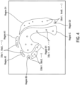
- FIG. 4 is a diagram showing a first example of a seed pixel selection method.
- the candidate area image data includes a code (a region label) indicating to which region each pixel of the medical image belongs, and the degree of accuracy (reliability) that the pixel is the code. Therefore, pixels of which the degree of accuracy is equal to or higher than a particular threshold may be selected as seed pixels for each of the regions.
- seed pixels ⁇ Sa1, Sa2, ... ⁇ are selected for which the degree of accuracy of the pixels in regions A1 and A2 separated from the region A is greater than or equal to the particular threshold.
- Seed pixels ⁇ Sb1, Sb2, ... ⁇ are selected for which the degree of accuracy of the pixels in regions B1 and B2 separated from the region B is greater than or equal to the particular threshold.
- Seed pixels ⁇ Sc 1, Sc2, ... ⁇ are selected for which the degree of accuracy of the pixels in the region C is greater than or equal to the particular threshold.
- Seed pixels ⁇ Sd1, Sd2, ... ⁇ are selected for which the degree of accuracy of the pixels in regions D1 and D2 separated from the region D is greater than or equal to the particular threshold.
- the seed pixel selection unit 57 may select seed pixels based on the degree of accuracy that the pixels in the identified candidate area are each of the regions.
- FIG. 5 is a diagram showing a second example of a seed pixel selection method.
- the seed pixel selection unit 57 may select the seed pixels from the largest candidate area among the candidate areas.
- the region A1 and the region A2 are identified as candidate areas for the region A.
- the seed pixels ⁇ Sa1, Sa2, ... ⁇ are selected for which the degree of accuracy of the pixels of the region A1, which is the largest candidate area, is equal to or higher than the particular threshold.
- the region B 1 and the region B2 are identified as candidate areas for the region B.
- the seed pixels ⁇ Sb 1, Sb2, ... ⁇ are selected for which the degree of accuracy of pixels in the region B1, which is the largest candidate area, is equal to or higher than the particular threshold.
- the region D1 and the region D2 are identified as candidate areas for the region D.
- the seed pixels ⁇ Sd1, Sd2, ... ⁇ are selected for which the degree of accuracy of the pixels of the region D1, which is the largest candidate area, is equal to or higher than the particular threshold.
- the number of multiple candidate areas of the same region is not limited to two as in FIG. 5 . Also, the number of seed pixels is not limited to the numbers illustrated in FIGS. 4 and 5 .
- suitable seed pixels may be obtained when there are multiple candidate areas of the same region that are separated from each other.
- the seed pixel selection unit 57 outputs the seed point image to the region identification unit 58.
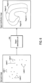
- FIG. 6 is a diagram showing an example of processing performed by the region identification unit 58.
- the area identification unit 56 outputs an image (a region identification image) in which the area of each of the regions is identified.
- the seed point image is an image in which seed pixels corresponding to each of the regions are identified.
- the seed point image includes seed points attached with label 1 corresponding to the region A, seed points attached with label 2 corresponding to the region B, seed points attached with label 3 corresponding to the region C, seed points attached with label 4 corresponding to the region D, and seed points attached with label 0 for pixels other than the regions A to D.
- the regions A to D are identified in the region identification image.
- each of the regions A to D is one continuous area, and the boundaries between the regions A to D are also clear.
- a region composed of the regions A to D is a whole region.
- the region identification unit 58 is capable of using a segmentation method using cellular automaton based on the seed pixels in the candidate area of each of the identified regions, for example, the GrowCut method, Graph-cuts method, Grab-cut method, or Random Walker method.
- the GrowCut method is to be described below.
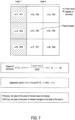
- FIG. 7 is a diagram showing an example of the GrowCut method.
- the seed point image is to be described as a 3 ⁇ 3 pixel block composed of a pixel of interest and surrounding eight pixels thereof.
- mc is regarded as the pixel value of the pixel of interest
- m1 to m8 are regarded as the pixel values of pixels 1 to 8.
- a pixel value may be a luminance value.
- the pixel value may take an integer value in the range of 0 to 255. It is assumed that pixels 1, 4, and 6 are attached with label 1, and the remaining pixels are attached with label 0.
- the pixels 1, 4, and 6 are assumed to be seed pixels (seed points).
- Rc and R1 to R8 are regarded as the degree of accuracy (reliability) of the labels of the pixel of interest and pixels 1 to 8, respectively.
- the degree of accuracy may take real values in the range 0 to 1.
- the GrowCut method uses the degree of familiarity F with adjacent pixels.
- F(c, i) 1-
- the region identification unit 58 changes the label and the accuracy of the pixel according to the magnitude of the degree of accuracy Rc of the pixel of interest and the aggression ability I(x) of the adjacent pixel x. For example, if Rc ⁇ I(x), the label of the pixel of interest (label 0 in this case) and the degree of accuracy Rc do not change. On the other hand, if Rc ⁇ I(x), the label of the pixel of interest changes to the label of the pixel x, and the degree of accuracy of the pixel of interest is updated with I(x). If the pixel x is pixel 1, the label of the pixel of interest changes to 1.
- the region identification unit 58 scans the entire image by moving the pixel of interest and performs similar processing.
- segmentation is automatically performed, and each pixel other than the seed pixels may be identified as to which region the pixel is.
- segmentation into two regions with labels 1 and 0 is taken as an example, but segmentation into three or more regions may also be performed in the same manner.
- the learning model 61 may be generated as follows. First, medical image data including multiple regions and segmentation image data created by making annotation based on the medical image data are prepared.
- a segmentation image is an image that indicates to which region each pixel of a medical image belongs, and may be generated by manual input or the like. Seed pixels (seed points) in the segmentation image are selected. The selection of seed pixels may be performed automatically by using the seed pixel selection unit 57, or may be performed manually.
- the area identification unit 56 outputs an image (a region identification image) in which each of the regions is identified.
- the medical image data including the regions described above and the area data (teacher data) indicating the area of each of the regions output by the region identification unit 58 are used as training data. A lot of training data are prepared.
- the learning model 61 may be generated by updating the internal parameters of the learning model 61 so that the area data of each of the regions output by the learning model 61 approaches the teacher data. In this way, when the medical image data including the regions is input, the learning model 61 may identify each of the regions, and the region identification unit 58 using the GrowCut method or the like may be removed.
- FIG. 8 is a diagram showing an example of a region identification screen 100.
- a display field 101 for subject information for example, subject ID, name, etc.
- a medical image display field 102 with an identified region for example, a measurement result field 103, and the like are displayed.
- the medical image display field 102 for example, the rectus femoris muscle A, the vastus medialis muscle B, the vastus intermedius muscle C, and the vastus lateralis muscle D of the quadriceps femoris muscle are clearly displayed, and each boundary thereof is also relatively clearly displayed.
- the processing unit 51 may display each of the identified regions in a different manner.
- the rectus femoris muscle A, the vastus medialis muscle B, the vastus intermedius muscle C, and the vastus lateralis muscle D are displayed in different patterns for convenience, for example, each of the regions may be displayed in a different color. In this way, each of the regions may be visually recognized easily.
- each of the regions may be identified with high accuracy.
- a threshold as a seed pixel (a seed point)
- the region identification unit 58 by using the region identification unit 58, the boundary of each of the regions becomes clear, and the area for each of the regions may be identified with high accuracy.
- manual setting of seed points may be removed, and the speed of processing may be increased.
- the measurement result field 103 may display the muscle mass of each of the rectus femoris muscle A, the vastus medialis muscle B, the vastus intermedius muscle C, and the vastus lateralis muscle D.
- the muscle mass may be calculated based on the size of each of the regions.
- Training data (second training data) used to generate the learning model 61 by relearning includes medical image data including multiple regions and teacher data corresponding to the medical image data. Area data (segmentation image data) of each of the regions identified by the region identification unit 58 is used as the teacher data. A large amount of the medical image data and the teacher data is prepared to relearn the learning model 61. That is, when the medical image data is input to the learning model 61, the learning model 61 may be relearned (be generated) by updating the internal parameters of the learning model 61 so that the area data of each of the regions output by the learning model 61 approaches the teacher data.
- the candidate area of each of the regions identified by the learning model 61 has fewer defects and outliers, and is more likely to match the actual area of each of the regions.
- the number of seed pixels input to the region identification unit 58 may be increased or the degree of accuracy that the seed pixel is a region of identification may be increased, thereby further improving the accuracy of identifying each of the regions.
- FIG. 9 is a diagram showing an example of an area correction screen 110 of a region.
- a medical image display field 112 an editing tool 113, an "edit” icon 114, and a "save” icon 115 are displayed on the area correction screen 110.
- the region may be one region or multiple regions
- the candidate area may be one candidate area or multiple candidate areas
- a user e.g., a doctor
- a cursor 116 is moved to the desired position of the region (or the candidate area of the region)
- editing tools in the editing tool 113 are used to correct the area of the region.
- the editing tools include icons for various tools, for example, a brush for drawing free lines by dragging operation on the image, a shape selection icon for drawing lines, curves, squares, circles, arrows, etc. on the image, a palette icon for changing the size of the pen tip, pattern or color, and an eraser for erasing a desired portion of the image.
- a boundary 117 of the area of the region may be corrected to become a boundary 118.
- the user may save the area data (the segmentation image data) of each of the regions after the correction by operating the "save" icon 115.
- the storage destination may be the storage unit 60 or an external data server or the like.
- the area data of each of the regions after the correction is stored in association with the corresponding medical image data, and may be used as training data for relearning of the learning model 61.
- the relearning processing unit 59 may relearn the learning model 61 by updating the internal parameters of the learning model 61 so that the candidate area image data output by the learning model 61 approaches the area data of each of the regions after the correction.
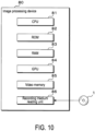
- FIG. 10 is a diagram showing another example of the configuration of an image processing device 80 of the embodiment.
- the image processing device 80 may use, for example, a personal computer.
- the image processing device 80 may be composed of a CPU 81, a ROM 82, a RAM 83, a GPU 84, a video memory 85, a recording medium reading unit 86, and the like.
- a computer program (a computer program product) recorded on a recording medium 1 (for example, an optically readable disk storage medium such as a CD-ROM) may be read by a recording medium reading unit 86 (for example, an optical disc drive) and stored in the RAM 83.
- the computer program (the computer program product) includes the processing procedure described in FIG. 11 , which is to be described later.
- the computer program (the computer program product) may be stored in a hard disk (not shown) and stored in the RAM 83 when the program is executed.
- each process in the input unit 52, the operation unit 53, and the processing unit 51 (the area identification unit 56, the region identification unit 58, and the relearning processing unit 59) may be executed.
- the video memory 85 may temporarily store data and processing results for various image processing.
- the computer program (the computer program product) instead of being read by the recording medium reading unit 86, may also be downloaded from other computers, network devices, etc. over a network such as the Internet.
- FIG. 11 is a flowchart showing a first example of the processing procedure of the image processing device 50.
- the processing unit 51 acquires a medical image (S11) and identifies a candidate area for each of regions (S12).
- the processing unit 51 selects seed pixels from the identified candidate area (S13). The seed pixels may be selected by using the method illustrated in FIG. 4 or FIG. 5 .
- the processing unit 51 identifies each of the regions based on the selected seed pixels (S14), and displays an image including each of the identified regions (S15).
- the processing unit 51 determines whether or not image editing operation exists (S16). If the editing operation exists (YES in S16), the image is corrected according to the editing operation (S17), and whether or not the operation has ended is determined (S18). Whether or not the operation has ended may be determined by whether or not the "save" icon 115 has been operated.
- step S17 If the operation has not ended (NO in S18), the processing unit 51 continues the process of step S17. If the operation is completed (YES in S18), the processing unit 51 stores the corrected image data (S19), and terminates the process. If no editing operation exists (NO in S16), the processing unit 51 terminates the process.
- FIG. 12 is a flowchart showing a second example of the processing procedure of the image processing device 50.
- the process shown in FIG. 12 shows an operational case in which a user such as a doctor uses the image processing device 50 to diagnose a patient.
- the processing unit 51 reads the learning model 61 from the storage unit 60 (S21), acquires a medical image (S22), and identifies each of regions (S23). Identification of each of the regions is performed by the area identification unit 56 and the region identification unit 58.
- the processing unit 51 displays an image including each of the identified regions (S24), and accepts corrections to the region of the image by the user (S25).
- the number of regions that accept corrections may be one or more.
- the processing unit 51 associates the acquired medical image with the area data of the region of the image for which the corrections are accepted, and stores the same in the storage unit 60 (S26).
- the processing unit 51 determines whether or not there are other medical images available (S27), and if there are other medical image (YES in S27), the process continues from step S22 onward. If there are no other medical images (NO in S27), the processing unit 51 relearns the learning model 61 based on the acquired medical image and the area data of the region of the image for which the corrections are accepted (S28). The processing unit 51 stores the relearned learning model 61 in the storage unit 60 (S29), and terminates the process. Relearning of the learning model 61 may be repeated by repeating the process shown in FIG. 12 as appropriate.
- FIG. 13 is a flowchart showing a first example of the processing procedure of the learning model 61 generation method.
- the learning model 61 may be generated by the image processing device 50 or by another device, but for the sake of convenience, the processing unit 51 is to be described below as the main body of processing.
- the processing unit 51 acquires first training data including medical image data and a candidate area (teacher data) of each of regions (S31).
- internal parameters of the learning model 61 are updated so that the candidate area image data output by the learning model 61 approaches the teacher data (S32). In this case, the internal parameters are adjusted so that a value of a loss function based on the candidate area image data output by the learning model 61 and the teacher data is minimized.
- the processing unit 51 determines whether or not the value of the loss function is within an allowable range (S33), and if the value of the loss function is not within the allowable range (NO in S33), the process continues from step S31 onward. If the value of the loss function is within the allowable range (YES in S33), the processing unit 51 identifies each of the regions based on the seed pixels in the candidate area of each of the regions identified by the learning model 61 (S34). Each of the regions may be identified by the region identification unit 58. A large amount of second training data, which is to be described later, may be collected by performing the process from steps S31 to S34.
- the processing unit 51 acquires the second training data including the medical image data included in the first training data and the area data of each of the identified regions as the teacher data (S35).
- the processing unit 51 inputs the medical image data to the learning model 61, the internal parameters of the learning model 61 are updated so that the area data of each of the regions output by the learning model 61 approaches the teacher data (S36).
- the internal parameters are adjusted so that the value of the loss function based on the area data of each of the regions output by the learning model 61 and the teacher data is minimized.
- the processing unit 51 determines whether or not the value of the loss function is within the allowable range (S37), and if the value of the loss function is not within the allowable range (NO in S37), the process continues from step S35 onward. If the value of the loss function is within the allowable range (YES in S37), the processing unit 51 stores the generated learning model 61 in the storage unit 60 (S38), and terminates the process.
- FIG. 14 is a flowchart showing a second example of the processing procedure of the learning model 61 generation method.
- the processing unit 51 acquires data including medical image data and a candidate area (teacher data) of each of regions (S41).
- the data of the candidate area of each of the regions is segmentation image data created by making annotation based on the medical image data.
- the processing unit 51 identifies each of the regions based on the seed pixels in the candidate area of each of the regions (S42). Each of the regions may be identified by the region identification unit 58.
- the processing unit 51 acquires training data including the medical image data and area data of each of the identified regions as the teacher data (S43).
- the processing unit 51 inputs the medical image data to the learning model 61, the internal parameters of the learning model 61 are updated so that the area data of each of the regions output by the learning model 61 approaches the teacher data (S44).
- the internal parameters are adjusted so that the value of the loss function based on the area data of each of the regions output by the learning model 61 and the teacher data is minimized.
- the processing unit 51 determines whether or not the value of the loss function is within an allowable range (S45), and if the value of the loss function is not within the allowable range (NO in S45), the process continues from step S43 onward. If the value of the loss function is within the allowable range (YES in S45), the processing unit 51 stores the generated learning model 61 in the storage unit 60 (S46), and terminates the process.
- a medical image including the quadriceps femoris muscle has been described, but the region is not limited to the quadriceps femoris muscle (thigh), and the imaging target may be the upper arm or the abdomen. Also, a medical image containing cells or the like may be used. Moreover, the image is not limited to a medical image, and may be an image for identifying an object, for example, the embodiment may be applied to an inspection image.
Landscapes
- Engineering & Computer Science (AREA)
- Computer Vision & Pattern Recognition (AREA)
- Physics & Mathematics (AREA)
- General Physics & Mathematics (AREA)
- Theoretical Computer Science (AREA)
- Image Analysis (AREA)
Abstract
Description
- The present invention relates to a computer program, a learning model generation method, an image processing method, and an image processing device.
- In order to assist doctors in diagnosis, a learning model generated using machine learning is used to automatically extract a desired region in a medical image. In order to generate such a learning model, teacher data has to be created in advance.
-
Patent Literature 1 discloses a teacher data generation device that generates teacher data in which a correct label is attached to each pixel of each of multiple images. - [Patent Literature 1]
Japanese Patent Application Laid-Open No. 2019-101535 - However, in order to generate a learning model which is capable of identifying regions (areas) with high accuracy, a large amount of data for learning, including teacher data, is required. Therefore, if sufficient data for learning cannot be prepared, there is a possibility that the accuracy of identifying the region decreases. In addition, when a clear medical image cannot be acquired, the accuracy of identifying the region also decreases.
- In view of such circumstances, the present invention is intended to provide a computer program, a learning model generation method, an image processing method, and an image processing device that are capable of identifying a region with high accuracy.
- A computer program according to the present invention causes a computer to execute processing of: acquiring a medical image including a plurality of regions; identifying the candidate area for each of the regions by inputting the medical image which is acquired to a learning model for identifying a candidate area for each of the regions when the medical image including the plurality of regions is input; and identifying an area for each of the regions based on seed pixels in the candidate area for each of the regions which is identified.
- The computer program according to the present invention causes the computer to execute processing of: displaying the area for each of the regions which is identified in a different manner.
- The computer program according to the present invention causes the computer to execute processing of: identifying the area for each of the regions by a GrowCut method, a Graph-cuts method, a Grab-cut method, or a Random Walker method based on the seed pixels in the candidate area for each of the regions which is identified.
- The computer program according to the present invention causes the computer to execute processing of: selecting the seed pixels based on a degree of accuracy for pixels in the candidate area for each of the regions which is identified to be in each of the regions.
- The computer program according to the present invention causes the computer to execute processing of: selecting the seed pixels from a largest candidate area among the plurality of candidate areas when there are a plurality of candidate areas for each of the regions that are identified.
- The computer program according to the present invention causes the computer to execute processing of: relearning the learning model based on the medical image including the plurality of regions and area data indicating the area for each of the regions which is identified.
- The computer program according to the present invention causes the computer to execute processing of: accepting a correction to the area for each of the regions which is identified from a user.
- The computer program according to the present invention causes the computer to execute processing of: relearning the learning model based on the medical image which is acquired and area data indicating the area for each of the regions for which the correction is accepted.
- In the computer program according to the present invention, the medical image includes an ultrasound image.
- In the computer program according to the present invention, an imaging target of the medical image is any of a thigh, an upper arm, and an abdomen.
- A learning model generation method according to the present invention includes: acquiring first training data including a medical image including a plurality of regions and a candidate area for each of the regions; generating a learning model to identify the candidate area for each of the regions when the medical image including the plurality of regions is input, based on the first training data; identifying an area for each of the regions based on seed pixels in the candidate area for each of the regions which is identified by the learning model; and generating the learning model to identify the area for each of the regions when the medical image including the plurality of regions is input, based on second training data including the medical image including the plurality of regions and area data indicating the area for each of the regions which is identified.
- A learning model generation method according to the present invention includes: acquiring data including a medical image including a plurality of regions and a candidate area for each of the regions; identifying an area for each of the regions based on seed pixels in the candidate area; and generating a learning model to identify the area for each of the regions when the medical image including the plurality of regions is input, based on training data including the medical image including the plurality of regions and area data indicating the area for each of the regions which is identified.
- An image processing method according to the present invention includes: acquiring a medical image including a plurality of regions; identifying the candidate area for each of the regions by inputting the medical image which is acquired to a learning model for identifying a candidate area for each of the regions when the medical image including the plurality of regions is input; and identifying an area for each of the regions based on seed pixels in the candidate area for each of the regions which is identified.
- An image processing device according to the present invention includes: an acquisition unit, acquiring a medical image including a plurality of regions; an area identification unit, identifying a candidate area for each of the regions by inputting the medical image which is acquired to a learning model for identifying a candidate area for each of the regions when the medical image including the plurality of regions is input; and a region identification unit, identifying an area for each of the regions based on seed pixels in the candidate area for each of the regions which is identified.
- The present invention enables identification of a region with high accuracy.
-
-
FIG. 1 is a diagram showing an example of the configuration of an image processing device of the embodiment. -
FIG. 2 is a diagram showing an example of the learning model. -
FIG. 3 is a diagram showing an example of processing performed by the area identification unit. -
FIG. 4 is a diagram showing a first example of a seed pixel selection method. -
FIG. 5 is a diagram showing a second example of a seed pixel selection method. -
FIG. 6 is a diagram showing an example of processing performed by the region identification unit. -
FIG. 7 is a diagram showing an example of the GrowCut method. -
FIG. 8 is a diagram showing an example of a region identification screen. -
FIG. 9 is a diagram showing an example of an area correction screen of a region. -
FIG. 10 is a diagram showing another example of the configuration of an image processing device of the embodiment. -
FIG. 11 is a flowchart showing a first example of the processing procedure of the image processing device. -
FIG. 12 is a flowchart showing a second example of the processing procedure of the image processing device. -
FIG. 13 is a flowchart showing a first example of the processing procedure of the learning model generation method. -
FIG. 14 is a flowchart showing a second example of the processing procedure of the learning model generation method. - An embodiment of the present invention is to be described below.
FIG. 1 is a diagram showing an example of the configuration of animage processing device 50 of the embodiment. Theimage processing device 50 includes aprocessing unit 51 that controls the entire device, aninput unit 52, anoperation unit 53, and adisplay unit 55. Theprocessing unit 51 includes animage processing unit 54. Theimage processing unit 54 includes anarea identification unit 56, aregion identification unit 58, arelearning processing unit 59, and astorage unit 60. Thearea identification unit 56 includes a seedpixel selection unit 57. Thestorage unit 60 stores alearning model 61. - The
processing unit 51 may be configured by a Central Processing Unit (CPU), a Read Only Memory (ROM), a Random Access Memory (RAM), and the like. - The
input unit 52 functions as an acquisition unit that acquires medical image data (medical images) via wired communication or wireless communication. Medical images include, for example, ultrasound images, MRI images, CT images, Positron Emission Tomography (PET) images, microscope images, and the like. Theinput unit 52 is capable of acquiring, for example, medical images from a device such as an ultrasonic diagnostic device, a computed tomography device, a magnetic resonance diagnostic device, an X-ray imaging device, an angiography X-ray diagnostic device, a PET examination device, or an electron microscope. Theinput unit 52 stores the acquired medical image data in thestorage unit 60 and outputs the acquired medical image data to thearea identification unit 56. - The
operation unit 53 is composed of, for example, a hardware keyboard, a mouse, etc., and is capable of operating icons displayed on thedisplay unit 55, moving and operating a cursor, and inputting characters. It should be noted that theoperation unit 53 may be configured by a touch panel. - The
display unit 55 may be configured by a liquid crystal panel, an organic Electro Luminescence (EL) display, or the like. - The
area identification unit 56 reads thelearning model 61 stored in thestorage unit 60 and inputs the medical image data acquired by theinput unit 52 to the readlearning model 61. When the medical image data is input, thelearning model 61 identifies a candidate area for each of multiple regions included in the medical image, and outputs the identified candidate area image data. The candidate area image data includes a code (a region label) indicating to which region each pixel of the medical image belongs, and the degree of accuracy (reliability) that the pixel is the code. -
FIG. 2 is a diagram showing an example of thelearning model 61. Thelearning model 61 may be configured by U-Net, for example. Thelearning model 61 includesencoders 601 to 605 and decoders 606 to 609. Thelearning model 61 repeats convolution processing with theencoders 601 to 605 on the input medical image data. Upsampling (deconvolution) processing of the image convoluted by theencoder 605 is repeated with the decoders 606 to 609. When decoding the convolved image, processing is performed to add the feature maps generated by theencoders 604 to 601 to the image to be deconvolved. Thelearning model 61 outputs a segmentation image (a candidate area image) of multiple regions included in the input medical image. From the segmentation image, it is possible to obtain the boundaries of each of the regions and the boundaries of the whole region including the regions. - The above configuration enables retention of the position information which is lost due to the convolution processing, and output of a more accurate segmentation (which pixel is which region). The
learning model 61 is not limited to U-Net and may be, for example, Generative Adversarial Network (GAN), SegNet, etc. - The
learning model 61 may be generated as follows. Training data (first training data) includes medical image data including multiple regions and teacher data. Segmentation image data created by making annotation based on the medical image data is used as the teacher data. The segmentation image is an image that indicates to which region each pixel of the medical image belongs. A large amount of the medical image data and the teacher data is prepared to machine-learn thelearning model 61. That is, when the medical image data is input to thelearning model 61, thelearning model 61 may be generated by updating the internal parameters of thelearning model 61 so that the candidate area image data output by thelearning model 61 approaches the teacher data. Thelearning model 61 may be generated by an external learning device, and the generatedlearning model 61 may be stored in thestorage unit 60. A learning processing unit may be provided in theimage processing device 50, and thelearning model 61 may be generated by theimage processing device 50. -
FIG. 3 is a diagram showing an example of processing performed by thearea identification unit 56. In the following, the quadriceps femoris muscle is to be described as an example of the whole region. As shown inFIG. 3 , when a medical image in which the quadriceps femoris muscle is captured is input to thearea identification unit 56, thearea identification unit 56 outputs a candidate area image. The candidate area image data includes candidate area data for each of region A, region B, region C, and region D as multiple regions. For the quadriceps femoris muscle, the regions A to D are rectus femoris muscle, vastus medialis muscle, vastus intermedius muscle, and vastus lateralis muscle, respectively. - If the medical image input to the
area identification unit 56 is partially unclear, such as an ultrasound image, or if the image is not clear as a whole, the candidate area image output by thearea identification unit 56 is not an area in which the same regions are continuous such as the regions A, B, and D, but multiple separated areas. Also, a gap is generated between each of the regions A to D, and the boundaries of each of the regions become unclear. In this way, missing areas and outlying areas occur in the candidate area image. Also, when the amount of training data used for learning by thelearning model 61 is not sufficient, a candidate area image such as the candidate area image shown inFIG. 3 is output. - In the embodiment, by using the
region identification unit 58 in addition to the area identification unit 56 (the learning model 61), multiple regions in the medical image may be identified with a high degree of accuracy. This point is to be described below. - The seed
pixel selection unit 57 selects seed pixels (seed points) based on the candidate area image output by thearea identification unit 56. The seedpixel selection unit 57 outputs the selected seed pixels to theregion identification unit 58. It should be noted that seed pixels may be manually selected from among the candidate area image output by thearea identification unit 56. -
FIG. 4 is a diagram showing a first example of a seed pixel selection method. The candidate area image data includes a code (a region label) indicating to which region each pixel of the medical image belongs, and the degree of accuracy (reliability) that the pixel is the code. Therefore, pixels of which the degree of accuracy is equal to or higher than a particular threshold may be selected as seed pixels for each of the regions. In the example ofFIG. 4 , seed pixels {Sa1, Sa2, ...} are selected for which the degree of accuracy of the pixels in regions A1 and A2 separated from the region A is greater than or equal to the particular threshold. Seed pixels {Sb1, Sb2, ...} are selected for which the degree of accuracy of the pixels in regions B1 and B2 separated from the region B is greater than or equal to the particular threshold. Seed pixels {Sc 1, Sc2, ...} are selected for which the degree of accuracy of the pixels in the region C is greater than or equal to the particular threshold. Seed pixels {Sd1, Sd2, ...} are selected for which the degree of accuracy of the pixels in regions D1 and D2 separated from the region D is greater than or equal to the particular threshold. In this way, the seedpixel selection unit 57 may select seed pixels based on the degree of accuracy that the pixels in the identified candidate area are each of the regions. -
FIG. 5 is a diagram showing a second example of a seed pixel selection method. When there are multiple candidate areas for each of the regions identified, the seedpixel selection unit 57 may select the seed pixels from the largest candidate area among the candidate areas. In the example ofFIG. 5 , the region A1 and the region A2 are identified as candidate areas for the region A. Among the regions A1 and A2, the seed pixels {Sa1, Sa2, ...} are selected for which the degree of accuracy of the pixels of the region A1, which is the largest candidate area, is equal to or higher than the particular threshold. Theregion B 1 and the region B2 are identified as candidate areas for the region B. Among the regions B1 and B2, the seed pixels {Sb 1, Sb2, ...} are selected for which the degree of accuracy of pixels in the region B1, which is the largest candidate area, is equal to or higher than the particular threshold. The region D1 and the region D2 are identified as candidate areas for the region D. Among the regions D1 and D2, the seed pixels {Sd1, Sd2, ...} are selected for which the degree of accuracy of the pixels of the region D1, which is the largest candidate area, is equal to or higher than the particular threshold. The number of multiple candidate areas of the same region is not limited to two as inFIG. 5 . Also, the number of seed pixels is not limited to the numbers illustrated inFIGS. 4 and5 . Although the second example shown inFIG. 5 is not critical, suitable seed pixels may be obtained when there are multiple candidate areas of the same region that are separated from each other. The seedpixel selection unit 57 outputs the seed point image to theregion identification unit 58. -
FIG. 6 is a diagram showing an example of processing performed by theregion identification unit 58. As shown inFIG. 6 , when a seed point image is input to theregion identification unit 58, thearea identification unit 56 outputs an image (a region identification image) in which the area of each of the regions is identified. The seed point image is an image in which seed pixels corresponding to each of the regions are identified. In the example ofFIG. 6 , the seed point image includes seed points attached withlabel 1 corresponding to the region A, seed points attached withlabel 2 corresponding to the region B, seed points attached withlabel 3 corresponding to the region C, seed points attached withlabel 4 corresponding to the region D, and seed points attached withlabel 0 for pixels other than the regions A to D. The regions A to D are identified in the region identification image. In the region identification image, each of the regions A to D is one continuous area, and the boundaries between the regions A to D are also clear. A region composed of the regions A to D is a whole region. - The
region identification unit 58 is capable of using a segmentation method using cellular automaton based on the seed pixels in the candidate area of each of the identified regions, for example, the GrowCut method, Graph-cuts method, Grab-cut method, or Random Walker method. The GrowCut method is to be described below. -
FIG. 7 is a diagram showing an example of the GrowCut method. For convenience, the seed point image is to be described as a 3×3 pixel block composed of a pixel of interest and surrounding eight pixels thereof. mc is regarded as the pixel value of the pixel of interest, and m1 to m8 are regarded as the pixel values ofpixels 1 to 8. A pixel value may be a luminance value. In this case, the pixel value may take an integer value in the range of 0 to 255. It is assumed thatpixels label 1, and the remaining pixels are attached withlabel 0. Here, thepixels pixels 1 to 8, respectively. The degree of accuracy may take real values in therange 0 to 1. The GrowCut method uses the degree of familiarity F with adjacent pixels. F(c, i)=1-|mc-mi|/255 (i=1, 2, ...,8) represents the degree of familiarity of eight pixels adjacent to the pixel of interest. For a pixel x with the largest product of a degree of accuracy Ri and the degree of familiarity F(c, i) of the adjacent pixel, the aggression ability I(x) is represented by I(x)=max{F(c, i) • Ri} and i=x. - The
region identification unit 58 changes the label and the accuracy of the pixel according to the magnitude of the degree of accuracy Rc of the pixel of interest and the aggression ability I(x) of the adjacent pixel x. For example, if Rc≧I(x), the label of the pixel of interest (label 0 in this case) and the degree of accuracy Rc do not change. On the other hand, if Rc<I(x), the label of the pixel of interest changes to the label of the pixel x, and the degree of accuracy of the pixel of interest is updated with I(x). If the pixel x ispixel 1, the label of the pixel of interest changes to 1. Theregion identification unit 58 scans the entire image by moving the pixel of interest and performs similar processing. - As described above, in the GrowCut method, merely by selecting pixels with a high degree of accuracy (for example, 1) as seed pixels (seed points) in the region of the image, segmentation is automatically performed, and each pixel other than the seed pixels may be identified as to which region the pixel is. In the example of
FIG. 7 , segmentation into two regions withlabels - Also, the
learning model 61 may be generated as follows. First, medical image data including multiple regions and segmentation image data created by making annotation based on the medical image data are prepared. A segmentation image is an image that indicates to which region each pixel of a medical image belongs, and may be generated by manual input or the like. Seed pixels (seed points) in the segmentation image are selected. The selection of seed pixels may be performed automatically by using the seedpixel selection unit 57, or may be performed manually. When the segmentation image in which the seed pixels are selected is input to theregion identification unit 58, thearea identification unit 56 outputs an image (a region identification image) in which each of the regions is identified. The medical image data including the regions described above and the area data (teacher data) indicating the area of each of the regions output by theregion identification unit 58 are used as training data. A lot of training data are prepared. When the medical image data is input to thelearning model 61 based on the training data, thelearning model 61 may be generated by updating the internal parameters of thelearning model 61 so that the area data of each of the regions output by thelearning model 61 approaches the teacher data. In this way, when the medical image data including the regions is input, thelearning model 61 may identify each of the regions, and theregion identification unit 58 using the GrowCut method or the like may be removed. -
FIG. 8 is a diagram showing an example of aregion identification screen 100. On theregion identification screen 100 displayed on thedisplay unit 55, adisplay field 101 for subject information (for example, subject ID, name, etc.), a medicalimage display field 102 with an identified region, ameasurement result field 103, and the like are displayed. In the medicalimage display field 102, for example, the rectus femoris muscle A, the vastus medialis muscle B, the vastus intermedius muscle C, and the vastus lateralis muscle D of the quadriceps femoris muscle are clearly displayed, and each boundary thereof is also relatively clearly displayed. - The
processing unit 51 may display each of the identified regions in a different manner. In the example ofFIG. 8 , the rectus femoris muscle A, the vastus medialis muscle B, the vastus intermedius muscle C, and the vastus lateralis muscle D are displayed in different patterns for convenience, for example, each of the regions may be displayed in a different color. In this way, each of the regions may be visually recognized easily. - In this way, even if the area for each of the regions cannot be clearly identified merely by the
area identification unit 56, among the candidate area of each of the regions identified by thearea identification unit 56, for example, by inputting a pixel of which accuracy is equal to or higher than a threshold as a seed pixel (a seed point) to theregion identification unit 58, each of the regions may be identified with high accuracy. In particular, when an ultrasound image is used as a medical image, the area of each of the regions is often unclear. However, according to the embodiment, by using theregion identification unit 58, the boundary of each of the regions becomes clear, and the area for each of the regions may be identified with high accuracy. In addition, manual setting of seed points may be removed, and the speed of processing may be increased. - The measurement result
field 103 may display the muscle mass of each of the rectus femoris muscle A, the vastus medialis muscle B, the vastus intermedius muscle C, and the vastus lateralis muscle D. The muscle mass may be calculated based on the size of each of the regions. - Next, relearning of the
learning model 61 is to be described. Training data (second training data) used to generate thelearning model 61 by relearning includes medical image data including multiple regions and teacher data corresponding to the medical image data. Area data (segmentation image data) of each of the regions identified by theregion identification unit 58 is used as the teacher data. A large amount of the medical image data and the teacher data is prepared to relearn thelearning model 61. That is, when the medical image data is input to thelearning model 61, thelearning model 61 may be relearned (be generated) by updating the internal parameters of thelearning model 61 so that the area data of each of the regions output by thelearning model 61 approaches the teacher data. In this way, when the medical image data including the regions is input to thelearning model 61, the candidate area of each of the regions identified by thelearning model 61 has fewer defects and outliers, and is more likely to match the actual area of each of the regions. As a result, the number of seed pixels input to theregion identification unit 58 may be increased or the degree of accuracy that the seed pixel is a region of identification may be increased, thereby further improving the accuracy of identifying each of the regions. -
FIG. 9 is a diagram showing an example of anarea correction screen 110 of a region. A medicalimage display field 112, anediting tool 113, an "edit"icon 114, and a "save"icon 115 are displayed on thearea correction screen 110. In the medicalimage display field 112, the region (may be one region or multiple regions) identified by theregion identification unit 58 or the candidate area (may be one candidate area or multiple candidate areas) of the region identified by thearea identification unit 56 may be displayed. As shown by A ofFIG. 9 , a user (e.g., a doctor) operates the "edit"icon 114, acursor 116 is moved to the desired position of the region (or the candidate area of the region), and editing tools in theediting tool 113 are used to correct the area of the region. The editing tools include icons for various tools, for example, a brush for drawing free lines by dragging operation on the image, a shape selection icon for drawing lines, curves, squares, circles, arrows, etc. on the image, a palette icon for changing the size of the pen tip, pattern or color, and an eraser for erasing a desired portion of the image. - For example, as shown by B of
FIG. 9 , aboundary 117 of the area of the region may be corrected to become aboundary 118. When the correction is completed, the user may save the area data (the segmentation image data) of each of the regions after the correction by operating the "save"icon 115. The storage destination may be thestorage unit 60 or an external data server or the like. The area data of each of the regions after the correction is stored in association with the corresponding medical image data, and may be used as training data for relearning of thelearning model 61. - That is, when the medical image data is input to the
learning model 61, the relearningprocessing unit 59 may relearn thelearning model 61 by updating the internal parameters of thelearning model 61 so that the candidate area image data output by thelearning model 61 approaches the area data of each of the regions after the correction. -
FIG. 10 is a diagram showing another example of the configuration of animage processing device 80 of the embodiment. As shown inFIG. 10 , theimage processing device 80 may use, for example, a personal computer. Theimage processing device 80 may be composed of aCPU 81, aROM 82, aRAM 83, aGPU 84, avideo memory 85, a recordingmedium reading unit 86, and the like. A computer program (a computer program product) recorded on a recording medium 1 (for example, an optically readable disk storage medium such as a CD-ROM) may be read by a recording medium reading unit 86 (for example, an optical disc drive) and stored in theRAM 83. Here, the computer program (the computer program product) includes the processing procedure described inFIG. 11 , which is to be described later. The computer program (the computer program product) may be stored in a hard disk (not shown) and stored in theRAM 83 when the program is executed. - By causing the
CPU 81 to execute the computer program (the computer program product) stored in theRAM 83, each process in theinput unit 52, theoperation unit 53, and the processing unit 51 (thearea identification unit 56, theregion identification unit 58, and the relearning processing unit 59) may be executed. Thevideo memory 85 may temporarily store data and processing results for various image processing. Further, the computer program (the computer program product), instead of being read by the recordingmedium reading unit 86, may also be downloaded from other computers, network devices, etc. over a network such as the Internet. -
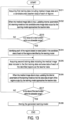
FIG. 11 is a flowchart showing a first example of the processing procedure of theimage processing device 50. For the sake of convenience, the main body of processing is to be described as theprocessing unit 51. Theprocessing unit 51 acquires a medical image (S11) and identifies a candidate area for each of regions (S12). Theprocessing unit 51 selects seed pixels from the identified candidate area (S13). The seed pixels may be selected by using the method illustrated inFIG. 4 orFIG. 5 . - The
processing unit 51 identifies each of the regions based on the selected seed pixels (S14), and displays an image including each of the identified regions (S15). Theprocessing unit 51 determines whether or not image editing operation exists (S16). If the editing operation exists (YES in S16), the image is corrected according to the editing operation (S17), and whether or not the operation has ended is determined (S18). Whether or not the operation has ended may be determined by whether or not the "save"icon 115 has been operated. - If the operation has not ended (NO in S18), the
processing unit 51 continues the process of step S17. If the operation is completed (YES in S18), theprocessing unit 51 stores the corrected image data (S19), and terminates the process. If no editing operation exists (NO in S16), theprocessing unit 51 terminates the process. -
FIG. 12 is a flowchart showing a second example of the processing procedure of theimage processing device 50. The process shown inFIG. 12 shows an operational case in which a user such as a doctor uses theimage processing device 50 to diagnose a patient. Theprocessing unit 51 reads thelearning model 61 from the storage unit 60 (S21), acquires a medical image (S22), and identifies each of regions (S23). Identification of each of the regions is performed by thearea identification unit 56 and theregion identification unit 58. - The
processing unit 51 displays an image including each of the identified regions (S24), and accepts corrections to the region of the image by the user (S25). The number of regions that accept corrections may be one or more. Theprocessing unit 51 associates the acquired medical image with the area data of the region of the image for which the corrections are accepted, and stores the same in the storage unit 60 (S26). - The
processing unit 51 determines whether or not there are other medical images available (S27), and if there are other medical image (YES in S27), the process continues from step S22 onward. If there are no other medical images (NO in S27), theprocessing unit 51 relearns thelearning model 61 based on the acquired medical image and the area data of the region of the image for which the corrections are accepted (S28). Theprocessing unit 51 stores the relearnedlearning model 61 in the storage unit 60 (S29), and terminates the process. Relearning of thelearning model 61 may be repeated by repeating the process shown inFIG. 12 as appropriate. -
FIG. 13 is a flowchart showing a first example of the processing procedure of thelearning model 61 generation method. Thelearning model 61 may be generated by theimage processing device 50 or by another device, but for the sake of convenience, theprocessing unit 51 is to be described below as the main body of processing. Theprocessing unit 51 acquires first training data including medical image data and a candidate area (teacher data) of each of regions (S31). When theprocessing unit 51 inputs the medical image data to thelearning model 61, internal parameters of thelearning model 61 are updated so that the candidate area image data output by thelearning model 61 approaches the teacher data (S32). In this case, the internal parameters are adjusted so that a value of a loss function based on the candidate area image data output by thelearning model 61 and the teacher data is minimized. - The
processing unit 51 determines whether or not the value of the loss function is within an allowable range (S33), and if the value of the loss function is not within the allowable range (NO in S33), the process continues from step S31 onward. If the value of the loss function is within the allowable range (YES in S33), theprocessing unit 51 identifies each of the regions based on the seed pixels in the candidate area of each of the regions identified by the learning model 61 (S34). Each of the regions may be identified by theregion identification unit 58. A large amount of second training data, which is to be described later, may be collected by performing the process from steps S31 to S34. - The
processing unit 51 acquires the second training data including the medical image data included in the first training data and the area data of each of the identified regions as the teacher data (S35). When theprocessing unit 51 inputs the medical image data to thelearning model 61, the internal parameters of thelearning model 61 are updated so that the area data of each of the regions output by thelearning model 61 approaches the teacher data (S36). In this case, the internal parameters are adjusted so that the value of the loss function based on the area data of each of the regions output by thelearning model 61 and the teacher data is minimized. - The
processing unit 51 determines whether or not the value of the loss function is within the allowable range (S37), and if the value of the loss function is not within the allowable range (NO in S37), the process continues from step S35 onward. If the value of the loss function is within the allowable range (YES in S37), theprocessing unit 51 stores the generatedlearning model 61 in the storage unit 60 (S38), and terminates the process. -
FIG. 14 is a flowchart showing a second example of the processing procedure of thelearning model 61 generation method. Theprocessing unit 51 acquires data including medical image data and a candidate area (teacher data) of each of regions (S41). In this case, the data of the candidate area of each of the regions is segmentation image data created by making annotation based on the medical image data. Theprocessing unit 51 identifies each of the regions based on the seed pixels in the candidate area of each of the regions (S42). Each of the regions may be identified by theregion identification unit 58. - The
processing unit 51 acquires training data including the medical image data and area data of each of the identified regions as the teacher data (S43). When theprocessing unit 51 inputs the medical image data to thelearning model 61, the internal parameters of thelearning model 61 are updated so that the area data of each of the regions output by thelearning model 61 approaches the teacher data (S44). In this case, the internal parameters are adjusted so that the value of the loss function based on the area data of each of the regions output by thelearning model 61 and the teacher data is minimized. - The
processing unit 51 determines whether or not the value of the loss function is within an allowable range (S45), and if the value of the loss function is not within the allowable range (NO in S45), the process continues from step S43 onward. If the value of the loss function is within the allowable range (YES in S45), theprocessing unit 51 stores the generatedlearning model 61 in the storage unit 60 (S46), and terminates the process. - In the embodiment, a medical image including the quadriceps femoris muscle has been described, but the region is not limited to the quadriceps femoris muscle (thigh), and the imaging target may be the upper arm or the abdomen. Also, a medical image containing cells or the like may be used. Moreover, the image is not limited to a medical image, and may be an image for identifying an object, for example, the embodiment may be applied to an inspection image.
-
- 50: image processing device
- 51: processing unit
- 52: input unit
- 53: operation unit
- 54: image processing unit
- 55: display unit
- 56: area identification unit
- 57: seed pixel selection unit
- 58: region identification unit
- 59: relearning processing unit
- 60: storage unit
- 61: learning model
- 601, 602, 603, 604, 605: encoders
- 606, 607, 608, 609: decoders
- 80: image processing device
- 81: CPU
- 82: ROM
- 83: RAM
- 84: GPU
- 85: video memory
- 86: recording medium reading unit
Claims (14)
- A computer program, causing a computer to execute processing of:acquiring a medical image comprising a plurality of regions;identifying a candidate area for each of the regions by inputting the medical image which is acquired to a learning model for identifying the candidate area for each of the regions when the medical image comprising the plurality of regions is input; andidentifying an area for each of the regions based on seed pixels in the candidate area for each of the regions which is identified.
- The computer program according to claim 1, causing the computer to execute processing of:
displaying the area for each of the regions which is identified in a different manner. - The computer program according to claim 1 or 2, causing the computer to execute processing of:
identifying the area for each of the regions by a GrowCut method, a Graph-cuts method, a Grab-cut method, or a Random Walker method based on the seed pixels in the candidate area for each of the regions which is identified. - The computer program according to any one of claims 1 to 3, causing the computer to execute processing of:
selecting the seed pixels based on a degree of accuracy for pixels in the candidate area for each of the regions which is identified to be in each of the regions. - The computer program according to any one of claims 1 to 4, causing the computer to execute processing of:
selecting the seed pixels from a largest candidate area among a plurality of candidate areas when there are the plurality of candidate areas for each of the regions which are identified. - The computer program according to any one of claims 1 to 5, causing the computer to execute processing of:
relearning the learning model based on the medical image comprising the plurality of regions and area data indicating the area for each of the regions which is identified. - The computer program according to any one of claims 1 to 6, causing the computer to execute processing of:
accepting a correction to the area for each of the regions which is identified from a user. - The computer program according to claim 7, causing the computer to execute processing of:
relearning the learning model based on the medical image which is acquired and area data indicating the area for each of the regions for which the correction is accepted. - The computer program according to any one of claims 1 to 8, wherein
the medical image comprises an ultrasound image. - The computer program according to any one of claims 1 to 9, wherein
an imaging target of the medical image is any of a thigh, an upper arm, and an abdomen. - A learning model generation method, comprising:acquiring first training data comprising a medical image comprising a plurality of regions and a candidate area for each of the regions;generating a learning model to identify the candidate area for each of the regions when the medical image comprising the plurality of regions is input, based on the first training data;identifying an area for each of the regions based on seed pixels in the candidate area for each of the regions which is identified by the learning model; andgenerating the learning model to identify the area for each of the regions when the medical image comprising the plurality of regions is input, based on second training data comprising the medical image comprising the plurality of regions and area data indicating the area for each of the regions which is identified.
- A learning model generation method, comprising:acquiring data comprising a medical image comprising a plurality of regions and a candidate area for each of the regions;identifying an area for each of the regions based on seed pixels in the candidate area; andgenerating a learning model to identify the area for each of the regions when the medical image comprising the plurality of regions is input, based on training data comprising the medical image comprising the plurality of regions and area data indicating the area for each of the regions which is identified.
- An image processing method, comprising:acquiring a medical image comprising a plurality of regions;identifying a candidate area for each of the regions by inputting the medical image which is acquired to a learning model for identifying the candidate area for each of the regions when the medical image comprising the plurality of regions is input; andidentifying an area for each of the regions based on seed pixels in the candidate area for each of the regions which is identified.
- An image processing device, comprising:an acquisition unit, acquiring a medical image comprising a plurality of regions;an area identification unit, identifying a candidate area for each of the regions by inputting the medical image which is acquired to a learning model for identifying the candidate area for each of the regions when the medical image comprising the plurality of regions is input; anda region identification unit, identifying an area for each of the regions based on seed pixels in the candidate area for each of the regions which is identified.
Applications Claiming Priority (2)
| Application Number | Priority Date | Filing Date | Title |
|---|---|---|---|
| JP2021093624 | 2021-06-03 | ||
| PCT/JP2022/010258 WO2022254859A1 (en) | 2021-06-03 | 2022-03-09 | Computer program, learning model generation method, image processing method, and image processing device |
Publications (2)
| Publication Number | Publication Date |
|---|---|
| EP4349267A1 true EP4349267A1 (en) | 2024-04-10 |
| EP4349267A4 EP4349267A4 (en) | 2025-06-04 |
Family
ID=84324228
Family Applications (1)
| Application Number | Title | Priority Date | Filing Date |
|---|---|---|---|
| EP22815616.2A Pending EP4349267A4 (en) | 2021-06-03 | 2022-03-09 | COMPUTER PROGRAM, LEARNING MODEL GENERATION METHOD, IMAGE PROCESSING METHOD, AND IMAGE PROCESSING DEVICE |
Country Status (4)
| Country | Link |
|---|---|
| EP (1) | EP4349267A4 (en) |
| JP (1) | JPWO2022254859A1 (en) |
| CN (1) | CN117321629A (en) |
| WO (1) | WO2022254859A1 (en) |
Family Cites Families (6)
| Publication number | Priority date | Publication date | Assignee | Title |
|---|---|---|---|---|
| JP6643827B2 (en) * | 2015-07-31 | 2020-02-12 | キヤノン株式会社 | Image processing apparatus, image processing method, and program |
| US10366490B2 (en) * | 2017-03-27 | 2019-07-30 | Siemens Healthcare Gmbh | Highly integrated annotation and segmentation system for medical imaging |
| JP2019101535A (en) | 2017-11-29 | 2019-06-24 | コニカミノルタ株式会社 | Teacher data preparation device and method thereof and image segmentation device and method thereof |
| US10964012B2 (en) * | 2018-06-14 | 2021-03-30 | Sony Corporation | Automatic liver segmentation in CT |
| EP3821813B1 (en) * | 2018-07-13 | 2024-07-31 | Furuno Electric Co., Ltd. | Ultrasound imaging device, ultrasound imaging system, ultrasound imaging method and ultrasound imaging program |
| JP2020170408A (en) * | 2019-04-04 | 2020-10-15 | キヤノン株式会社 | Image processing device, image processing method, program |
-
2022
- 2022-03-09 JP JP2023525413A patent/JPWO2022254859A1/ja active Pending
- 2022-03-09 WO PCT/JP2022/010258 patent/WO2022254859A1/en not_active Ceased
- 2022-03-09 CN CN202280034385.6A patent/CN117321629A/en active Pending
- 2022-03-09 EP EP22815616.2A patent/EP4349267A4/en active Pending
Also Published As
| Publication number | Publication date |
|---|---|
| WO2022254859A1 (en) | 2022-12-08 |
| EP4349267A4 (en) | 2025-06-04 |
| JPWO2022254859A1 (en) | 2022-12-08 |
| CN117321629A (en) | 2023-12-29 |
Similar Documents
| Publication | Publication Date | Title |
|---|---|---|
| RU2739713C1 (en) | Training annotation of objects in an image | |
| CN100506155C (en) | Medical image display apparatus | |
| US9152760B2 (en) | Smart 3D PACS workflow by learning | |
| EP3181050B1 (en) | System and method for creating a decision support material indicating damage to an anatomical joint | |
| US20180225824A1 (en) | Systems and methods for interleaving series of medical images | |
| US20080118237A1 (en) | Auto-Zoom Mark-Up Display System and Method | |
| JP2003175023A (en) | Radiographic scoring method | |
| US11250561B2 (en) | Determination and visualization of damage to an anatomical joint | |
| CN101657819A (en) | Hanging protocol display system and method | |
| US20090087047A1 (en) | Image display device and image display program storage medium | |
| US20180365827A1 (en) | Creation of a decision support material indicating damage to an anatomical joint | |
| US20220130042A1 (en) | Determination and visualization of damage to an anatomical joint | |
| Smit et al. | RegistrationShop: An Interactive 3D Medical Volume Registration System. | |
| JP2009080545A (en) | Medical information processing equipment | |
| EP4349267A1 (en) | Computer program, learning model generation method, image processing method, and image processing device | |
| Sugathan et al. | Longitudinal visualization for exploratory analysis of multiple sclerosis lesions | |
| JP2020523049A (en) | Creation of decision support material showing anatomical joint damage | |
| US12315622B2 (en) | Medical image paging display system | |
| CN108630301B (en) | Feature marking method and device and computer storage medium | |
| WO2021072873A1 (en) | Grayscale image processing method, system, device, and computer-readable storage medium | |
| JPH10261038A (en) | Image display device | |
| WO2007146495A2 (en) | Selection of image filters based on image information | |
| JP5100041B2 (en) | Image processing apparatus and image processing program | |
| EP4524900A1 (en) | Method and system for improved interaction with medical 2d and 3d visualization | |
| JP7805337B2 (en) | Computer program, image processing device, image processing system, and image processing method |
Legal Events
| Date | Code | Title | Description |
|---|---|---|---|
| STAA | Information on the status of an ep patent application or granted ep patent |
Free format text: STATUS: THE INTERNATIONAL PUBLICATION HAS BEEN MADE |
|
| PUAI | Public reference made under article 153(3) epc to a published international application that has entered the european phase |
Free format text: ORIGINAL CODE: 0009012 |
|
| STAA | Information on the status of an ep patent application or granted ep patent |
Free format text: STATUS: REQUEST FOR EXAMINATION WAS MADE |
|
| 17P | Request for examination filed |
Effective date: 20231128 |
|
| AK | Designated contracting states |
Kind code of ref document: A1 Designated state(s): AL AT BE BG CH CY CZ DE DK EE ES FI FR GB GR HR HU IE IS IT LI LT LU LV MC MK MT NL NO PL PT RO RS SE SI SK SM TR |
|
| DAV | Request for validation of the european patent (deleted) | ||
| DAX | Request for extension of the european patent (deleted) | ||
| REG | Reference to a national code |
Ref country code: DE Ref legal event code: R079 Free format text: PREVIOUS MAIN CLASS: A61B0008140000 Ipc: G06T0007110000 |
|
| A4 | Supplementary search report drawn up and despatched |
Effective date: 20250507 |
|
| RIC1 | Information provided on ipc code assigned before grant |
Ipc: A61B 8/14 20060101ALI20250429BHEP Ipc: G06T 7/162 20170101ALI20250429BHEP Ipc: G06T 7/11 20170101AFI20250429BHEP |
|
| STAA | Information on the status of an ep patent application or granted ep patent |
Free format text: STATUS: EXAMINATION IS IN PROGRESS |
|
| 17Q | First examination report despatched |
Effective date: 20251216 |