EP4348091B1 - Schnellkupplungsanordnung mit verbindungsverriegelungskolben - Google Patents
Schnellkupplungsanordnung mit verbindungsverriegelungskolben Download PDFInfo
- Publication number
- EP4348091B1 EP4348091B1 EP22729691.0A EP22729691A EP4348091B1 EP 4348091 B1 EP4348091 B1 EP 4348091B1 EP 22729691 A EP22729691 A EP 22729691A EP 4348091 B1 EP4348091 B1 EP 4348091B1
- Authority
- EP
- European Patent Office
- Prior art keywords
- piston
- chamber
- female coupling
- coupling
- head
- Prior art date
- Legal status (The legal status is an assumption and is not a legal conclusion. Google has not performed a legal analysis and makes no representation as to the accuracy of the status listed.)
- Active
Links
Images



Classifications
-
- F—MECHANICAL ENGINEERING; LIGHTING; HEATING; WEAPONS; BLASTING
- F16—ENGINEERING ELEMENTS AND UNITS; GENERAL MEASURES FOR PRODUCING AND MAINTAINING EFFECTIVE FUNCTIONING OF MACHINES OR INSTALLATIONS; THERMAL INSULATION IN GENERAL
- F16L—PIPES; JOINTS OR FITTINGS FOR PIPES; SUPPORTS FOR PIPES, CABLES OR PROTECTIVE TUBING; MEANS FOR THERMAL INSULATION IN GENERAL
- F16L37/00—Couplings of the quick-acting type
- F16L37/22—Couplings of the quick-acting type in which the connection is maintained by means of balls, rollers or helical springs under radial pressure between the parts
- F16L37/23—Couplings of the quick-acting type in which the connection is maintained by means of balls, rollers or helical springs under radial pressure between the parts by means of balls
-
- F—MECHANICAL ENGINEERING; LIGHTING; HEATING; WEAPONS; BLASTING
- F16—ENGINEERING ELEMENTS AND UNITS; GENERAL MEASURES FOR PRODUCING AND MAINTAINING EFFECTIVE FUNCTIONING OF MACHINES OR INSTALLATIONS; THERMAL INSULATION IN GENERAL
- F16L—PIPES; JOINTS OR FITTINGS FOR PIPES; SUPPORTS FOR PIPES, CABLES OR PROTECTIVE TUBING; MEANS FOR THERMAL INSULATION IN GENERAL
- F16L37/00—Couplings of the quick-acting type
- F16L37/28—Couplings of the quick-acting type with fluid cut-off means
- F16L37/30—Couplings of the quick-acting type with fluid cut-off means with fluid cut-off means in each of two pipe-end fittings
- F16L37/32—Couplings of the quick-acting type with fluid cut-off means with fluid cut-off means in each of two pipe-end fittings at least one of two lift valves being opened automatically when the coupling is applied
- F16L37/35—Couplings of the quick-acting type with fluid cut-off means with fluid cut-off means in each of two pipe-end fittings at least one of two lift valves being opened automatically when the coupling is applied at least one of the valves having an axial bore communicating with lateral apertures
-
- F—MECHANICAL ENGINEERING; LIGHTING; HEATING; WEAPONS; BLASTING
- F16—ENGINEERING ELEMENTS AND UNITS; GENERAL MEASURES FOR PRODUCING AND MAINTAINING EFFECTIVE FUNCTIONING OF MACHINES OR INSTALLATIONS; THERMAL INSULATION IN GENERAL
- F16L—PIPES; JOINTS OR FITTINGS FOR PIPES; SUPPORTS FOR PIPES, CABLES OR PROTECTIVE TUBING; MEANS FOR THERMAL INSULATION IN GENERAL
- F16L37/00—Couplings of the quick-acting type
- F16L37/28—Couplings of the quick-acting type with fluid cut-off means
- F16L37/30—Couplings of the quick-acting type with fluid cut-off means with fluid cut-off means in each of two pipe-end fittings
- F16L37/36—Couplings of the quick-acting type with fluid cut-off means with fluid cut-off means in each of two pipe-end fittings with two lift valves being actuated to initiate the flow through the coupling after the two coupling parts are locked against withdrawal
Definitions
- the present invention relates to a quick coupling assembly with a connection locking piston.
- the quick coupling assembly comprises a female coupling and a male coupling, wherein the male coupling is suitable for fitting into the female coupling which is associated with a machine, e.g., a tractor, while the male coupling is associated with a piece of equipment, e.g., a weeder, to be connected to the machine.
- a machine e.g., a tractor
- a piece of equipment e.g., a weeder
- US-2020/0332937 describes a quick coupling assembly comprising a female coupling and a male coupling, wherein the male coupling is suitable for being inserted into the female coupling making a pressurized hydraulic connection between the female coupling and the male coupling.
- the female coupling comprises an external body fixed to a machine, e.g., a tractor, and an internal body sliding axially into a cavity in the external body.
- the female coupling comprises a head, in which the connection to the male coupling occurs, and a back, in which connection to the machine occurs.
- the female coupling further comprises a piston suitable for moving radially, i.e. in a direction orthogonal to the axis of the quick coupling assembly along which the connection movement between the female coupling and the male coupling takes place.
- the piston is suitable for moving between a first position, in which the connection between the female coupling and the male coupling is permitted, and a second position, in which said connection is prohibited.
- the piston comprises a head and a stem.
- the through-hole puts the cavity of the female coupling into fluid communication with a chamber located above the piston head.
- the piston head is wider than the stem.
- a spring which acts in the direction of the piston axis, in particular, it biases the piston to move towards the outside of the female coupling, i.e. it tends to reduce the protrusion of the lower end of the piston stem into the cavity of the female coupling.
- a pressure exhaust channel is in communication with the bottom of the piston head, where the spring is located.
- the piston moves along its axis as a function of the difference in force induced by the spring (outward thrust) and the hydraulic pressure (inward thrust) on the piston head.
- the spring is calibrated so that beyond a pressure threshold value in the female coupling cavity, the piston moves into the second position, i.e. towards the inside, preventing the sliding of the internal sliding body of the female coupling; the connection between the female coupling and the male coupling cannot take place.
- the calibration of the spring is very complex; the dimensions of the stem and the head must be taken into account with accuracy.
- the spring seat is very small because the female coupling cavity must have sufficient space for the internal body of the female coupling to slide. Consequently, it is not possible to mount springs with excessive load, i.e. the piston can remain in a useful position for connection only for low pressure values, lower than 10 bar of normal use.
- the piston prefferably be easy to actuate and maintain the actuating threshold value over time.
- the piston seat is non-invasive, i.e., easily integrated into the female coupling without forcing complicated and costly design changes to the female coupling.
- the hydraulic pressure which pushes the full piston into the second position, the locked position acts in only one direction, completely over the full piston head. Only the spring acts in the opposite direction.
- the sizing of the full piston and spring is simple, having to consider in practice only the dimensions of the full piston in its radial seat.
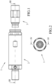
- a quick coupling assembly 1 suitable for connecting pressurized hydraulic lines according to the present invention comprises a female coupling 2 and a male coupling 3 which can be connected to the female coupling 2 ( figure 1 ).
- the female coupling 2 is associated with a machine (not shown), e.g., a tractor, while the male coupling 3 is associated with a piece of working equipment, e.g., a weeder.
- the female coupling 2 comprises an external part 4 integral with the machine, and an internal part 5 sliding along a connection axis X inside the external part 4.
- the external part 4 of the female coupling 2 comprises a junction 6 for connecting to the machine, a female body 7 and a ring nut 8 integral with each other.
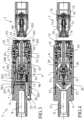
- the internal part 5 of the female coupling 2 comprises a sliding body 9, a shutter 10, a ring nut holder 11 suitable for containing balls 12 in a locking seat 111 ( figure 4 ), and a pin 13 integral with the sliding body 9 with which a pressure exhaust valve 17 is also associated.
- the shutter 10 has a head 101 and a stem 102, wherein the head 101 is in one piece with the stem 102.
- the head 101 comprises a flat end 103 facing the male coupling 3; the head 101 expands radially toward the flat end 103.
- a spring 14 is provided between the external portion 4 and the internal portion 5 suitable for keeping the female coupling 2 in the rest position when it is separated from the male coupling 3.
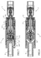
- the cup 15 comprises a thrust portion 155 ( figure 5 ) suitable for moving the balls 12 into an exhaust seat 81 of the ring nut 8 ( figure 7 ).
- the internal portion 5 also comprises a sleeve 50 through which the stem 102 of the coupling 10 passes.
- the sleeve 50 is suitable for sliding axially, i.e. along the connection axis X, relative to both the sliding body 9 and the coupling 10.
- the sleeve 50 has an end 51 which interacts in a sealing manner with the head 101 of the shutter 10, wherein a spring 53 is suitable for forcing said seal.
- the sleeve 50 comprises a radial shim 52 suitable for receiving in abutment a complementary shim 151 of the cup 15, which is suitable for canceling the seal of the sleeve 50 on the shutter 10, as will be explained in greater detail below.
- the pressure exhaust valve 17 is associated with a back 91 of the sliding body 9, wherein said back 91 is elastically associated with a spring 60 to a rear end 105 of the coupling 10 by means of a guide body 106 integral with the shutter 10.
- the external part 4 and the internal part 5 are shaped to form a single chamber 18, in which the hydraulic pressure generated by the machine, of at least roughly 10 bars, is present.
- Said single chamber 18 comprises ( figure 4 ) a head chamber 19 about the shutter 10 (partly inside the sleeve 50), two first oblique chambers 20 suitable to take the working pressure outside the internal part 5, an external chamber 21 between the junction 6 and the female body 7, two second oblique chambers 22 and a rear chamber 23.
- the second oblique chambers 22 connect the external chamber 21 to the rear chamber 23, which is connected to the machine.
- the first oblique chambers 20 pass through both the sliding body 9 and the junction 6, which is also crossed by the second oblique chambers 22.
- the external chamber 21 is in communication with a through chamber 241 of a sleeve 24 integral with the junction 6, which provides a radial seat 25 for a full piston 26 ( figure 3 ).
- radial means a direction orthogonal to that of the connection axis X.
- the sleeve 24 is suitable for making an upper limit stop of the full piston 26.
- the full piston 26 comprises a head 261 and a stem 262.
- Full piston 26 means a piston with a full head and stem, i.e. without through cavities, in particular without a through cavity along the radial direction in which the piston moves, between the head of the piston and the bottom of the stem.
- a spring 27, inserted into a chamber 29, is suitable for pushing the full piston 26 into a stop towards the sleeve 24.
- An upper surface 263 of the head 261 of the full piston 26 faces the through chamber 241 of the sleeve 24.
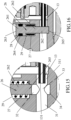
- the head 261 of the full piston 26 ( figure 16 ) provides a lateral seat 264 for a gasket 28 suitable for ensuring sealing between the through chamber 241, i.e., the single chamber 18, and the chamber 29 of the spring 27, wherein said radial seat 25 is in hydraulic connection with an exhaust duct 30 formed in the junction 6.
- the full piston 26 has no through cavities, i.e. there is a pressure seal between the single chamber 18 and exhaust duct 30.
- the exhaust duct 30 is hydraulically connected to a pressure exhaust chamber 90 which faces the back of the internal portion 5 in which the pressure exhaust valve 17 is provided.
- the exhaust duct 30 ( figure 15 ) comprises an axial oriented channel 31 parallel to the connection axis X, and a radial oriented channel 32 orthogonal to said axial oriented channel 31.
- the radial channel 32 is adapted to guide a bottom 265 of the stem 262.
- the pin 13 has a longitudinal development in the axial direction and is suitable for sliding in the axial oriented channel 31.
- the stem 262 of the full piston 26 is suitable for flowing into the axial oriented channel 31 at a junction 33.
- the axial oriented channel 31 comprises a portion of the head 311 adjacent to the junction 33.
- the full piston 26 is suitable for sliding between a first position ( figure 15 ), in which the piston head 261 abuts the limit stop on the sleeve 24 and the bottom 265 of the stem 262 is completely within the radial oriented channel 32, i.e., does not protrude into the axial oriented channel 31 at the junction 33, and a second position, in which the bottom 265 protrudes from the radial oriented channel 32 into the axial oriented channel 31 at the junction 33.
- Figure 16 shows the bottom 265 which connects to a seat 34 arriving at a lower limit stop; a portion of the stem 262 obstructs the axial oriented channel 31 in the junction 33.
- the pin 13, guided by the sliding body 9, is suitable for sliding between a first position ( figure 15 ), in which a free end 131 of the pin 13 is completely inside the head portion 311 of the axial oriented duct 31, and a second position ( figure 7 ) in which the free end 131 protrudes from the head portion 311 in the junction 33.
- the free end 131 of the pin 13 cannot enter the junction 33, i.e., its axial movement toward the junction 33 is limited by the stem 262 of the full piston 26, which then obstructs the junction 33.
- the male coupling 3 ( figure 4 ) comprises a male body 70, a shutter 71 sliding axially into the male body 70, and a junction 72 suitable for connecting to a piece of equipment (not shown).
- the shutter 71 is also suitable for sliding relative to an internal body 76 housed in and integral with the male body 70.
- a spring 73 holds a head 74 of the shutter 71 in a sealing manner on the male body 70, while an internal valve 75 is suitable for putting the male coupling 3 into fluid communication with the equipment (not shown).
- the radial ends of the shutter 71 and the male body 70 of the male coupling 3 form a flat face of the male coupling 3.
- the ends of the shutter 10 and the cup 15 of the female coupling 2 form a flat face of the female coupling 2.
- connection occurs if the pressure in the single chamber 18 is below a threshold value, e.g., when the machine is off, namely in the case in which connection between the female coupling 2 and the male coupling 3 is allowed.
- a threshold value e.g., when the machine is off, namely in the case in which connection between the female coupling 2 and the male coupling 3 is allowed.
- the threshold value preferably coincides with the operating pressure of the machine, typically 10 bar.
- the male body 70 axially pushes the cup 15 backwards (towards the bottom of the female coupling 2, i.e., leftwards when looking at the figures), which moves the balls 12 from their locking seat 111 to the exhaust seat 81 of the ring nut 8 ( figure 7 ).
- the cup 15 by means of the balls 12 which move the ring nut holder 11, also pushes back the sliding body 9 which is integral with the ring nut holder 11; in the absence of overpressure beyond the defined threshold value, the pin 13 can move axially in the junction 33, under the full piston 26 stopped in the first position ( figures 7 , 9 ).
- the thrust of the cup 15 is opposed to a ring nut spring 82 which acts on the ring nut holder 11 through a shim 112 ( figure 7 ).
- the radial shim 151 of the cup 15 comes into contact with the radial shim 52 of the sleeve 50, which retracts thus opening the hydraulic line between the female coupling 2 and the male coupling 3.
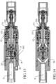
- the balls 12 from the exhaust seat 81 of the ring nut 8, pushed by the ring nut spring 82, are inserted into an external seat 90 of the male body 70 thus making the connection stable ( figures 11, 12 ).
- the sliding body 9, fed by the ring nut holder 11, is moved forward again (rightwards observing the figures) thus freeing the junction 33 from the pin 13 again.
- the cup 15 does not interact with the sleeve 50 ( figures 9, 10 ), which thus remains sealed to the head 101 of the shutter 10.
- the pressure which pushes the full piston 26 into the second position, the locked position acts in only one direction, completely on the upper surface 263 of the head 261 of the full piston 26.
- the sizing of the full piston 26 and spring 27 is simple, because in practice only the dimensions of the full piston 26 in its radial seat 25 need to be considered, with no through cavities complicating design calculations.
- oblique channels 20, 22 allows easily taking the pressure outside the sliding body 9 without needing to pierce the full piston 26, which is, therefore, more solid, stable and responsive to overpressure.
- the full piston 26 moves by even intersecting the connection axis X without limiting the stroke of the sliding body 9.
- a wall for the pressure exhaust valve 17 is provided between the radial seat 25 of the full piston 26 and the sliding body 9.
- the radial seat 25 of the full piston 26 can be enlarged to use heavily loaded springs 27.
Landscapes
- Engineering & Computer Science (AREA)
- General Engineering & Computer Science (AREA)
- Mechanical Engineering (AREA)
- Quick-Acting Or Multi-Walled Pipe Joints (AREA)
Claims (8)
- Schnellkupplungsanordnung (1), die zum Verbinden von unter Druck stehenden Hydraulikleitungen geeignet ist, mit einer Buchse (2) und einem Stecker (3), der mit der Buchse (2) verbindbar ist, wobei die Buchse (2) mit einer Maschine verbindbar ist, die zum Erzeugen von Hydraulikdruck geeignet ist, während der Stecker (3) mit einer Ausrüstung verbindbar ist,wobei die Buchse (2) ein Außenteil (4), das an der Maschine befestigbar ist, einen Kolben (26) und ein Innenteil (5) aufweist, das entlang einer Verbindungsachse (X) im Innern des Außenteils (4) gleitet, wobei die Verbindungsachse (X) eine axiale Richtung definiert,wobei das Außenteil (4) und das Innenteil (5) so geformt sind, dass sie eine einzelne Kammer (18) bilden, die geeignet ist, den von der Maschine erzeugten hydraulischen Druck aufrechtzuerhalten,wobei das Außenteil (4) einen radialen Sitz (25) für den Kolben (26) aufweist, der sich radial zwischen einer ersten Position, in der die Verbindung zwischen der Buchse (2) und dem Stecker (3) zugelassen wird, und einer zweiten Position bewegen kann, in der die Verbindung zwischen der Buchse (2) und dem Stecker (3) aufgrund der Beeinflussung zwischen dem Innenteil (5) und dem Kolben (26) verhindert wird,wobei der Kolben (26) die zweite Position einnimmt, wenn in der Buchse (2) ein Hydraulikdruck herrscht, der gleich oder größer als ein Schwellenwert ist,wobei der Kolben (26) einen Kopf (261) und einen Schaft (262) aufweist, wobei der Kopf (261) einen seitlichen Sitz (264) für eine Dichtung (28) bereitstellt, die dazu geeignet ist, die Abdichtung zwischen der einzelnen Kammer (18) und einer Kammer (29) zu gewährleisten, in der eine Feder (27) untergebracht ist, die dazu geeignet ist, den Kolben (26) in die erste Position zu drücken,wobei die Kammer (29), in der die Feder (27) untergebracht ist, in hydraulischer Verbindung mit einem Auslasskanal (30) steht,dadurch gekennzeichnet, dassder Kolben (26) ein Vollkolben ohne durchgehende Hohlräume ist.
- Anordnung (1) nach Anspruch 1, dadurch gekennzeichnet, dass der Auslasskanal (30) einen axial ausgerichteten Kanal (31) und einen radial ausgerichteten Kanal (32) aufweist, der an einer Verbindungsstelle (33) des Auslasskanals (30) in den axial ausgerichteten Kanal (31) mündet,wobei ein Stift (13), der mit dem Innenteil (5) einstückig ist, entlang des axial ausgerichteten Kanals (31) gleitet, während ein Boden (265) des Schafts (262) entlang des radial ausgerichteten Kanals (32) gleitet,wobei sich in der ersten Position des Vollkolbens (26) der Boden (265) des Schafts (262) vollständig innerhalb des radial ausgerichteten Kanals (32) befindet, während in der zweiten Position des Vollkolbens (26) der Boden (265) aus dem radial ausgerichteten Kanal (32) in den axial ausgerichteten Kanal (31) an der Verbindungsstelle (33) hineinragt, wodurch verhindert wird, dass der Stift (13) in die Verbindungsstelle (33) und dementsprechend in die Verbindung zwischen der Buchse (2) und dem Stecker (3) gleitet.
- Anordnung (1) nach Anspruch 2, dadurch gekennzeichnet, dass die einzelne Kammer (18) eine Kopfkammer (19), zwei erste schräge Kammern (20), eine Außenkammer (21) zwischen dem Außenteil (4) und dem Innenteil (5), zwei zweite schräge Kammern (22) und eine hintere Kammer (23) aufweist, wobei die beiden ersten schrägen Kammern (20) die Kopfkammer (19) und die Außenkammer (21) verbinden und wobei die zweiten schrägen Kammern (22) die Außenkammer (21) und die hintere Kammer (23), die mit der Maschine verbunden ist, hydraulisch verbinden.
- Anordnung (1) nach Anspruch 3, dadurch gekennzeichnet, dass die Außenkammer (21) in hydraulischer Verbindung mit einer Durchgangskammer (241) einer Hülse (24) steht, die mit dem Außenteil (4) einstückig ist, wobei die Hülse (24) geeignet ist, einen oberen Anschlag des Vollkolbens (26) zu realisieren, der durch die Feder (27) gedrückt wird, wobei eine obere Fläche (263) des Kopfes (261) des Vollkolbens (26) der Durchgangskammer (241) der Hülse (24) zugewandt ist, wobei der Hydraulikdruck der Maschine direkt auf die obere Fläche (263) in entgegengesetzter Richtung zur Kraft der Feder (27) wirkt.
- Anordnung (1) nach Anspruch 2, dadurch gekennzeichnet, dass der Stift (13) zwischen einer ersten Position, in der ein freies Ende (131) des Stifts (13) vollständig innerhalb eines Kopfabschnitts (311) des axial ausgerichteten Kanals (31) liegt, und einer zweiten Position, in der das freie Ende (131) aus dem Kopfabschnitt (311) in der Verbindung (33) herausragt, verschiebbar ist.
- Anordnung (1) nach Anspruch 3, dadurch gekennzeichnet, dass vom Kopf bis zum hinteren Teil der Buchse (2) die ersten schrägen Kammern (20) in Bezug auf die Verbindungsachse (X) divergieren, während die zweiten schrägen Kammern (22) in Bezug auf dieselbe Verbindungsachse (X) konvergieren.
- Anordnung (1) nach Anspruch 2, dadurch gekennzeichnet, dassdas Außenteil (4) einstückig miteinander eine Verbindungsstelle (6) zum Anschluss an die Maschine, einen Buchsenkörper (7) und eine Ringmutter (8) umfasst,der Innenteil (5) einen Gleitkörper (9), einen Verschluss (10) und einen Ringmutterhalter (11) umfasst, der zur Aufnahme von Kugeln (12) geeignet ist, wobei der Stift (13) einstückig mit dem Gleitkörper (9) ist.
- Anordnung (1) nach Anspruch 7, dadurch gekennzeichnet, dass die ersten schrägen Kammern (20) sowohl durch den Gleitkörper (9) als auch durch die Verbindungsstelle (6) verlaufen, die auch von den zweiten schrägen Kammern (22) durchquert wird.
Applications Claiming Priority (2)
| Application Number | Priority Date | Filing Date | Title |
|---|---|---|---|
| IT102021000013823A IT202100013823A1 (it) | 2021-05-27 | 2021-05-27 | Assemblato di innesto rapido con pistone di blocco all’accoppiamento. |
| PCT/EP2022/063694 WO2022248350A1 (en) | 2021-05-27 | 2022-05-20 | Quick coupling assembly with connection locking piston |
Publications (2)
| Publication Number | Publication Date |
|---|---|
| EP4348091A1 EP4348091A1 (de) | 2024-04-10 |
| EP4348091B1 true EP4348091B1 (de) | 2025-02-26 |
Family
ID=77412171
Family Applications (1)
| Application Number | Title | Priority Date | Filing Date |
|---|---|---|---|
| EP22729691.0A Active EP4348091B1 (de) | 2021-05-27 | 2022-05-20 | Schnellkupplungsanordnung mit verbindungsverriegelungskolben |
Country Status (4)
| Country | Link |
|---|---|
| EP (1) | EP4348091B1 (de) |
| AR (1) | AR125916A1 (de) |
| IT (1) | IT202100013823A1 (de) |
| WO (1) | WO2022248350A1 (de) |
Families Citing this family (1)
| Publication number | Priority date | Publication date | Assignee | Title |
|---|---|---|---|---|
| IT202300021054A1 (it) | 2023-10-10 | 2025-04-10 | Stucchi Spa | “assemblato di innesto rapido con pistone di blocco all’accoppiamento e ridotta perdita di carico” |
Family Cites Families (3)
| Publication number | Priority date | Publication date | Assignee | Title |
|---|---|---|---|---|
| US6830059B1 (en) * | 2003-09-08 | 2004-12-14 | Snap-Tite Technologies, Inc. | Low spill farm coupling |
| FR2914980B1 (fr) * | 2007-04-10 | 2012-05-11 | Staubli Sa Ets | Element femelle de raccord et raccord comprenant un tel element femelle |
| DE102017126459B4 (de) * | 2017-11-10 | 2021-07-08 | U.M. Gewerbeimmobilien Gmbh & Co. Kg | Kupplungselement für eine Hydraulikkupplung |
-
2021
- 2021-05-27 IT IT102021000013823A patent/IT202100013823A1/it unknown
-
2022
- 2022-05-19 AR ARP220101333A patent/AR125916A1/es unknown
- 2022-05-20 WO PCT/EP2022/063694 patent/WO2022248350A1/en not_active Ceased
- 2022-05-20 EP EP22729691.0A patent/EP4348091B1/de active Active
Also Published As
| Publication number | Publication date |
|---|---|
| WO2022248350A1 (en) | 2022-12-01 |
| IT202100013823A1 (it) | 2022-11-27 |
| AR125916A1 (es) | 2023-08-23 |
| EP4348091A1 (de) | 2024-04-10 |
Similar Documents
| Publication | Publication Date | Title |
|---|---|---|
| US5535985A (en) | Quick coupling for pressure conduit with controlled disengagement | |
| US4881573A (en) | Female hydraulic coupler with push-connect and lever disconnect | |
| US4150691A (en) | Quick disconnect coupling | |
| US7887102B2 (en) | Quick coupling for joining together two pipes for conveying a gas under pressure | |
| US5002254A (en) | Automatic coupler for pressurized fluid circuit | |
| US6095190A (en) | Coupling with female half having internal pressure relief | |
| US4598896A (en) | Quick disconnect coupling | |
| EP2204599B1 (de) | Schnellkupplung für Hochdruckanwendungen | |
| CA2207263C (en) | Quick-release coupling | |
| US4249572A (en) | Self-relieving fluid coupling | |
| US20020134959A1 (en) | Universal safety coupler | |
| US20140145430A1 (en) | Female quick-connect coupling element, and a quick-connect coupling incorporating such an element | |
| CN107869621B (zh) | 耦合件和用于包含这种耦合件的自行车的液压制动回路 | |
| US3646964A (en) | Coupling device for permitting coupling under trapped pressure | |
| EP1269064B1 (de) | Verbindung mit einsteckteil und interner druckentlastung | |
| KR20030057393A (ko) | 래치트 기구를 구비한 유압식 장력기 | |
| EP3292341B1 (de) | Unter druck einrastbare schnellkupplungsmuffe | |
| CA2273593C (en) | Farm coupling | |
| EP4348091A1 (de) | Schnellkupplungsanordnung mit verbindungsverriegelungskolben | |
| US4792162A (en) | Protective device for quick connect coupling | |
| US11054075B2 (en) | Coupling element for a hydraulic coupling | |
| US5918633A (en) | Farm coupling | |
| US20060273580A1 (en) | Coupling for a hydraulic or pneumatic assembly | |
| CN109162975B (zh) | 一种用在农机上的带有跳位和保压功能的换向阀片 | |
| US4322114A (en) | Hydraulic pressure control device for double hydraulic piping for vehicle brakes |
Legal Events
| Date | Code | Title | Description |
|---|---|---|---|
| STAA | Information on the status of an ep patent application or granted ep patent |
Free format text: STATUS: UNKNOWN |
|
| STAA | Information on the status of an ep patent application or granted ep patent |
Free format text: STATUS: THE INTERNATIONAL PUBLICATION HAS BEEN MADE |
|
| PUAI | Public reference made under article 153(3) epc to a published international application that has entered the european phase |
Free format text: ORIGINAL CODE: 0009012 |
|
| STAA | Information on the status of an ep patent application or granted ep patent |
Free format text: STATUS: REQUEST FOR EXAMINATION WAS MADE |
|
| 17P | Request for examination filed |
Effective date: 20231218 |
|
| AK | Designated contracting states |
Kind code of ref document: A1 Designated state(s): AL AT BE BG CH CY CZ DE DK EE ES FI FR GB GR HR HU IE IS IT LI LT LU LV MC MK MT NL NO PL PT RO RS SE SI SK SM TR |
|
| DAV | Request for validation of the european patent (deleted) | ||
| DAX | Request for extension of the european patent (deleted) | ||
| GRAP | Despatch of communication of intention to grant a patent |
Free format text: ORIGINAL CODE: EPIDOSNIGR1 |
|
| STAA | Information on the status of an ep patent application or granted ep patent |
Free format text: STATUS: GRANT OF PATENT IS INTENDED |
|
| INTG | Intention to grant announced |
Effective date: 20241031 |
|
| RIN1 | Information on inventor provided before grant (corrected) |
Inventor name: TIVELLI, SERGIO Inventor name: LA ROSA, DAVIDE Inventor name: GATTI, GIANMARCO |
|
| GRAS | Grant fee paid |
Free format text: ORIGINAL CODE: EPIDOSNIGR3 |
|
| GRAA | (expected) grant |
Free format text: ORIGINAL CODE: 0009210 |
|
| STAA | Information on the status of an ep patent application or granted ep patent |
Free format text: STATUS: THE PATENT HAS BEEN GRANTED |
|
| AK | Designated contracting states |
Kind code of ref document: B1 Designated state(s): AL AT BE BG CH CY CZ DE DK EE ES FI FR GB GR HR HU IE IS IT LI LT LU LV MC MK MT NL NO PL PT RO RS SE SI SK SM TR |
|
| REG | Reference to a national code |
Ref country code: GB Ref legal event code: FG4D |
|
| REG | Reference to a national code |
Ref country code: CH Ref legal event code: EP |
|
| REG | Reference to a national code |
Ref country code: DE Ref legal event code: R096 Ref document number: 602022011184 Country of ref document: DE |
|
| REG | Reference to a national code |
Ref country code: IE Ref legal event code: FG4D |
|
| REG | Reference to a national code |
Ref country code: NL Ref legal event code: MP Effective date: 20250226 |
|
| PG25 | Lapsed in a contracting state [announced via postgrant information from national office to epo] |
Ref country code: RS Free format text: LAPSE BECAUSE OF FAILURE TO SUBMIT A TRANSLATION OF THE DESCRIPTION OR TO PAY THE FEE WITHIN THE PRESCRIBED TIME-LIMIT Effective date: 20250526 |
|
| PG25 | Lapsed in a contracting state [announced via postgrant information from national office to epo] |
Ref country code: FI Free format text: LAPSE BECAUSE OF FAILURE TO SUBMIT A TRANSLATION OF THE DESCRIPTION OR TO PAY THE FEE WITHIN THE PRESCRIBED TIME-LIMIT Effective date: 20250226 |
|
| PG25 | Lapsed in a contracting state [announced via postgrant information from national office to epo] |
Ref country code: PL Free format text: LAPSE BECAUSE OF FAILURE TO SUBMIT A TRANSLATION OF THE DESCRIPTION OR TO PAY THE FEE WITHIN THE PRESCRIBED TIME-LIMIT Effective date: 20250226 |
|
| PG25 | Lapsed in a contracting state [announced via postgrant information from national office to epo] |
Ref country code: ES Free format text: LAPSE BECAUSE OF FAILURE TO SUBMIT A TRANSLATION OF THE DESCRIPTION OR TO PAY THE FEE WITHIN THE PRESCRIBED TIME-LIMIT Effective date: 20250226 |
|
| REG | Reference to a national code |
Ref country code: LT Ref legal event code: MG9D |
|
| PG25 | Lapsed in a contracting state [announced via postgrant information from national office to epo] |
Ref country code: IS Free format text: LAPSE BECAUSE OF FAILURE TO SUBMIT A TRANSLATION OF THE DESCRIPTION OR TO PAY THE FEE WITHIN THE PRESCRIBED TIME-LIMIT Effective date: 20250626 Ref country code: NO Free format text: LAPSE BECAUSE OF FAILURE TO SUBMIT A TRANSLATION OF THE DESCRIPTION OR TO PAY THE FEE WITHIN THE PRESCRIBED TIME-LIMIT Effective date: 20250526 |
|
| PG25 | Lapsed in a contracting state [announced via postgrant information from national office to epo] |
Ref country code: NL Free format text: LAPSE BECAUSE OF FAILURE TO SUBMIT A TRANSLATION OF THE DESCRIPTION OR TO PAY THE FEE WITHIN THE PRESCRIBED TIME-LIMIT Effective date: 20250226 |
|
| PG25 | Lapsed in a contracting state [announced via postgrant information from national office to epo] |
Ref country code: HR Free format text: LAPSE BECAUSE OF FAILURE TO SUBMIT A TRANSLATION OF THE DESCRIPTION OR TO PAY THE FEE WITHIN THE PRESCRIBED TIME-LIMIT Effective date: 20250226 |
|
| PG25 | Lapsed in a contracting state [announced via postgrant information from national office to epo] |
Ref country code: LV Free format text: LAPSE BECAUSE OF FAILURE TO SUBMIT A TRANSLATION OF THE DESCRIPTION OR TO PAY THE FEE WITHIN THE PRESCRIBED TIME-LIMIT Effective date: 20250226 Ref country code: PT Free format text: LAPSE BECAUSE OF FAILURE TO SUBMIT A TRANSLATION OF THE DESCRIPTION OR TO PAY THE FEE WITHIN THE PRESCRIBED TIME-LIMIT Effective date: 20250626 |
|
| PG25 | Lapsed in a contracting state [announced via postgrant information from national office to epo] |
Ref country code: GR Free format text: LAPSE BECAUSE OF FAILURE TO SUBMIT A TRANSLATION OF THE DESCRIPTION OR TO PAY THE FEE WITHIN THE PRESCRIBED TIME-LIMIT Effective date: 20250527 Ref country code: BG Free format text: LAPSE BECAUSE OF FAILURE TO SUBMIT A TRANSLATION OF THE DESCRIPTION OR TO PAY THE FEE WITHIN THE PRESCRIBED TIME-LIMIT Effective date: 20250226 |
|
| REG | Reference to a national code |
Ref country code: AT Ref legal event code: MK05 Ref document number: 1770926 Country of ref document: AT Kind code of ref document: T Effective date: 20250226 |
|
| PG25 | Lapsed in a contracting state [announced via postgrant information from national office to epo] |
Ref country code: SE Free format text: LAPSE BECAUSE OF FAILURE TO SUBMIT A TRANSLATION OF THE DESCRIPTION OR TO PAY THE FEE WITHIN THE PRESCRIBED TIME-LIMIT Effective date: 20250226 |
|
| PG25 | Lapsed in a contracting state [announced via postgrant information from national office to epo] |
Ref country code: SM Free format text: LAPSE BECAUSE OF FAILURE TO SUBMIT A TRANSLATION OF THE DESCRIPTION OR TO PAY THE FEE WITHIN THE PRESCRIBED TIME-LIMIT Effective date: 20250226 |
|
| PG25 | Lapsed in a contracting state [announced via postgrant information from national office to epo] |
Ref country code: DK Free format text: LAPSE BECAUSE OF FAILURE TO SUBMIT A TRANSLATION OF THE DESCRIPTION OR TO PAY THE FEE WITHIN THE PRESCRIBED TIME-LIMIT Effective date: 20250226 |
|
| PG25 | Lapsed in a contracting state [announced via postgrant information from national office to epo] |
Ref country code: IT Free format text: LAPSE BECAUSE OF FAILURE TO SUBMIT A TRANSLATION OF THE DESCRIPTION OR TO PAY THE FEE WITHIN THE PRESCRIBED TIME-LIMIT Effective date: 20250226 |
|
| PG25 | Lapsed in a contracting state [announced via postgrant information from national office to epo] |
Ref country code: AT Free format text: LAPSE BECAUSE OF FAILURE TO SUBMIT A TRANSLATION OF THE DESCRIPTION OR TO PAY THE FEE WITHIN THE PRESCRIBED TIME-LIMIT Effective date: 20250226 |
|
| PG25 | Lapsed in a contracting state [announced via postgrant information from national office to epo] |
Ref country code: EE Free format text: LAPSE BECAUSE OF FAILURE TO SUBMIT A TRANSLATION OF THE DESCRIPTION OR TO PAY THE FEE WITHIN THE PRESCRIBED TIME-LIMIT Effective date: 20250226 Ref country code: CZ Free format text: LAPSE BECAUSE OF FAILURE TO SUBMIT A TRANSLATION OF THE DESCRIPTION OR TO PAY THE FEE WITHIN THE PRESCRIBED TIME-LIMIT Effective date: 20250226 |
|
| PG25 | Lapsed in a contracting state [announced via postgrant information from national office to epo] |
Ref country code: RO Free format text: LAPSE BECAUSE OF FAILURE TO SUBMIT A TRANSLATION OF THE DESCRIPTION OR TO PAY THE FEE WITHIN THE PRESCRIBED TIME-LIMIT Effective date: 20250226 |
|
| PG25 | Lapsed in a contracting state [announced via postgrant information from national office to epo] |
Ref country code: SK Free format text: LAPSE BECAUSE OF FAILURE TO SUBMIT A TRANSLATION OF THE DESCRIPTION OR TO PAY THE FEE WITHIN THE PRESCRIBED TIME-LIMIT Effective date: 20250226 |
|
| REG | Reference to a national code |
Ref country code: DE Ref legal event code: R097 Ref document number: 602022011184 Country of ref document: DE |
|
| REG | Reference to a national code |
Ref country code: DE Ref legal event code: R119 Ref document number: 602022011184 Country of ref document: DE |
|
| REG | Reference to a national code |
Ref country code: CH Ref legal event code: H13 Free format text: ST27 STATUS EVENT CODE: U-0-0-H10-H13 (AS PROVIDED BY THE NATIONAL OFFICE) Effective date: 20251223 |
|
| PLBE | No opposition filed within time limit |
Free format text: ORIGINAL CODE: 0009261 |
|
| STAA | Information on the status of an ep patent application or granted ep patent |
Free format text: STATUS: NO OPPOSITION FILED WITHIN TIME LIMIT |
|
| PG25 | Lapsed in a contracting state [announced via postgrant information from national office to epo] |
Ref country code: LU Free format text: LAPSE BECAUSE OF NON-PAYMENT OF DUE FEES Effective date: 20250520 |
|
| PG25 | Lapsed in a contracting state [announced via postgrant information from national office to epo] |
Ref country code: CH Free format text: LAPSE BECAUSE OF NON-PAYMENT OF DUE FEES Effective date: 20250531 |
|
| REG | Reference to a national code |
Ref country code: BE Ref legal event code: MM Effective date: 20250531 |
|
| PG25 | Lapsed in a contracting state [announced via postgrant information from national office to epo] |
Ref country code: MC Free format text: LAPSE BECAUSE OF FAILURE TO SUBMIT A TRANSLATION OF THE DESCRIPTION OR TO PAY THE FEE WITHIN THE PRESCRIBED TIME-LIMIT Effective date: 20250226 |
|
| 26N | No opposition filed |
Effective date: 20251127 |
|
| PG25 | Lapsed in a contracting state [announced via postgrant information from national office to epo] |
Ref country code: DE Free format text: LAPSE BECAUSE OF NON-PAYMENT OF DUE FEES Effective date: 20251202 Ref country code: IE Free format text: LAPSE BECAUSE OF NON-PAYMENT OF DUE FEES Effective date: 20250520 |
|
| PG25 | Lapsed in a contracting state [announced via postgrant information from national office to epo] |
Ref country code: BE Free format text: LAPSE BECAUSE OF NON-PAYMENT OF DUE FEES Effective date: 20250531 |
|
| PG25 | Lapsed in a contracting state [announced via postgrant information from national office to epo] |
Ref country code: FR Free format text: LAPSE BECAUSE OF NON-PAYMENT OF DUE FEES Effective date: 20250531 |
|
| PG25 | Lapsed in a contracting state [announced via postgrant information from national office to epo] |
Ref country code: LT Free format text: LAPSE BECAUSE OF FAILURE TO SUBMIT A TRANSLATION OF THE DESCRIPTION OR TO PAY THE FEE WITHIN THE PRESCRIBED TIME-LIMIT Effective date: 20250226 |
|
| PG25 | Lapsed in a contracting state [announced via postgrant information from national office to epo] |
Ref country code: CY Free format text: LAPSE BECAUSE OF FAILURE TO SUBMIT A TRANSLATION OF THE DESCRIPTION OR TO PAY THE FEE WITHIN THE PRESCRIBED TIME-LIMIT Effective date: 20250226 |