EP4347310B1 - Remote handle assembly - Google Patents
Remote handle assembly Download PDFInfo
- Publication number
- EP4347310B1 EP4347310B1 EP22755326.0A EP22755326A EP4347310B1 EP 4347310 B1 EP4347310 B1 EP 4347310B1 EP 22755326 A EP22755326 A EP 22755326A EP 4347310 B1 EP4347310 B1 EP 4347310B1
- Authority
- EP
- European Patent Office
- Prior art keywords
- handle
- pulley
- pin
- spline
- assembly
- Prior art date
- Legal status (The legal status is an assumption and is not a legal conclusion. Google has not performed a legal analysis and makes no representation as to the accuracy of the status listed.)
- Active
Links
Images


Classifications
-
- B—PERFORMING OPERATIONS; TRANSPORTING
- B60—VEHICLES IN GENERAL
- B60N—SEATS SPECIALLY ADAPTED FOR VEHICLES; VEHICLE PASSENGER ACCOMMODATION NOT OTHERWISE PROVIDED FOR
- B60N2/00—Seats specially adapted for vehicles; Arrangement or mounting of seats in vehicles
- B60N2/02—Seats specially adapted for vehicles; Arrangement or mounting of seats in vehicles the seat or part thereof being movable, e.g. adjustable
- B60N2/20—Seats specially adapted for vehicles; Arrangement or mounting of seats in vehicles the seat or part thereof being movable, e.g. adjustable the back-rest being tiltable, e.g. to permit easy access
-
- B—PERFORMING OPERATIONS; TRANSPORTING
- B60—VEHICLES IN GENERAL
- B60N—SEATS SPECIALLY ADAPTED FOR VEHICLES; VEHICLE PASSENGER ACCOMMODATION NOT OTHERWISE PROVIDED FOR
- B60N2/00—Seats specially adapted for vehicles; Arrangement or mounting of seats in vehicles
- B60N2/02—Seats specially adapted for vehicles; Arrangement or mounting of seats in vehicles the seat or part thereof being movable, e.g. adjustable
- B60N2/22—Seats specially adapted for vehicles; Arrangement or mounting of seats in vehicles the seat or part thereof being movable, e.g. adjustable the back-rest being adjustable
-
- B—PERFORMING OPERATIONS; TRANSPORTING
- B60—VEHICLES IN GENERAL
- B60Y—INDEXING SCHEME RELATING TO ASPECTS CROSS-CUTTING VEHICLE TECHNOLOGY
- B60Y2400/00—Special features of vehicle units
- B60Y2400/40—Actuators for moving a controlled member
- B60Y2400/41—Mechanical transmissions for actuators
- B60Y2400/411—Bowden cables or linkages
Definitions
- the seat assemblies often include a remote handle assembly attached to the seat assembly and configured to selectively unlock the recliner assembly. It is commonly known for the remote handle assembly to include a handle rotatable by an occupant and configured to actuate the remote handle assembly to unlock the recliner assembly and allow the occupant to adjust the seat back position. In addition, it is commonly known for the remote handle assembly to be optionally actuated by a power actuator, such as when the seat assembly includes a fold flat feature.
- a remote handle assembly for selectively unlocking a component in a seat assembly for an automotive vehicle.
- the remote handle assembly comprises a handle bracket having a hole extending laterally through the handle bracket, a pulley having a pivot hole extending axially through the pulley, a handle spline having a passageway extending axially through the handle spline, and a pin extending through the passageway in the handle spline, the pivot hole in the pulley, and the hole in the handle bracket, wherein the pulley is pivotably coupled to the pin between an unactuated position and an actuated position and the handle spline is pivotably coupled to the pin between an unactuated position and an actuated position and the pin is fixedly coupled to the handle bracket and is configured to retain the handle bracket, the pulley and the handle spline together.
- a seat assembly for an automotive vehicle.
- the seat assembly comprises a seat cushion, a seat back pivotably coupled to the seat cushion, a recliner assembly configured to prevent rotation of the seat back relative to the seat cushion, and a remote handle assembly for selectively unlocking the recliner assembly.
- the remote handle assembly comprises a handle bracket having a hole extending laterally through the handle bracket, wherein the handle bracket is adapted to be mounted on the seat cushion, a pulley having a pivot hole extending axially through the pulley, a handle spline having a passageway extending axially through the handle spline, and a pin extending through the passageway in the handle spline, the pivot hole in the pulley, and the hole in the handle bracket, wherein the pulley is pivotably coupled to the pin between an unactuated position and an actuated position and the handle spline is pivotably coupled to the pin between an unactuated position and an actuated position and the pin is fixedly coupled to the handle bracket and is configured to retain the handle bracket, the pulley and the handle spline together.
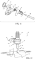
- Figures 1-21 illustrate components of a seat assembly 10 for use in an automotive vehicle according to embodiments described herein.
- Directional references employed or shown in the description, figures, or claims, such as top, bottom, upper, lower, upward, downward, lengthwise, widthwise, left, right, and the like, are relative terms employed for ease of description and are not intended to limit the scope of the invention in any respect.
- like numerals indicate like or corresponding parts throughout the several views.
- the seat assembly 10 includes a seat back 12 pivotably coupled to a seat cushion 14 by inboard and outboard recliner assemblies 16.
- the recliner assemblies 16 are configured to prevent rotation of the seat back 12 relative to the seat cushion 14 while the recliner assemblies 16 are locked.
- the recliner assemblies 16 are selectively unlocked by actuating release levers 18 operatively coupled to the respective recliner assemblies 16.
- the seat assembly 10 includes a remote handle assembly 20 configured to actuate the release levers 18 to remotely unlock the recliner assemblies 16.
- a first embodiment of the remote handle assembly 20 is shown in Figures 2-16 .
- the remote handle assembly 20 includes a handle spline 22, a pulley 24 and a handle bracket 26.
- the pulley 24 is pivotably coupled with both the handle spline 22 and the handle bracket 26.
- the pulley 24 includes a hub 48 and a sector 50 projecting radially from the hub 48.
- a pivot hole 52 extends axially through the hub 48 and defines an axis of rotation of the pulley 24.
- Opposing primary cable channels 54 extend circumferentially along an outer portion of the sector 50 and terminate in a retention hole 56 passing axially through the sector 50.
- a passageway 58 extends between each cable channel 54 and each retention hole 56.
- a secondary cable channel 60 extends circumferentially along the outer portion of the sector 50 and terminates at an end wall 62 having a cable hole 64 extending circumferentially therethrough.
- the pulley 24 includes a ledge 66 projecting from a distal surface 68 of the pulley 24.
- the ledge 66 is configured to frictionally engage with the cam surface 46 on the actuator tab 44, as shown in Figure 4 .
- the pulley 24 is formed out of a plastic such as nylon 6/6, as a non-limiting example.
- the handle bracket 26 includes a keyed hole 70, a spring hole 72, and opposing attachment slots 74, 76 extending laterally through the handle bracket 26.
- the keyed hole 70 has a double d-shape.
- the handle bracket 26 is formed from steel as a non-limiting example.
- the remote handle assembly 20 also includes a pin 78 configured to retain the components of the remote handle assembly 20 together.
- the pin 78 includes a central section 80 extending from a head 82.
- the central section 80 has a double d-shape in cross-section with generally parallel side walls 84 extending between curved end walls 86.
- the central section 80 is sized and shaped such that it will pass through and be pivotably coupled to the passageway 32 in the handle spline 22 while the head 82 is sized and shaped such that it will not pass through the passageway 32 in the handle spline 22.
- a ledge 88 on the proximal end of the head 82 extends radially from the central section 80.
- a generally cylindrical section 90 projects axially away from the central section 80 of the pin 78.
- the cylindrical section 90 is sized and shaped such that it will pass through and be pivotably coupled to the pivot hole 52 in the hub 48 of the pulley 24.
- a stop ledge 92 on the proximal end of the central section 80 extends radially from the cylindrical section 90.
- Projecting axially from the cylindrical section 90 and forming a proximal end of the pin 78 is an end section 94.
- a base ledge 96 on the proximal end of the cylindrical section 90 projects radially from the end section 94.
- the end section 94 of the pin 78 and the keyed hole 70 in the handle bracket 26 are sized and shaped such that the end section 94 will pass through the keyed hole 70 in the handle bracket 26, but will not rotate within the keyed hole 70.
- the end section 94 of the pin 78 and the keyed hole 70 in the handle bracket 26 have a double d-shape, as a non-limiting example.
- the pin 78 is formed out of a carbon steel, such as SAE J403 grade 1018, as a non-limiting example.
- the remote handle assembly 20 also includes a spline spring 104, such as a coil spring, a torsion spring, or the like.
- the spline spring 104 is formed out of music wire such as ASTM A228, as a non-limiting example.
- the spline spring 104 is operatively coupled between the handle spline 22 and the pin 78 with the spline spring 104 applying a bias force to the handle spine 22 urging the handle spline 22 to rotate in the clockwise direction (arrow 102) as viewed in Figure 2 .
- the spring geometry of the spline spring 104 and the pulley spring 98 may be adjusted to meet torque requirements of different seat assemblies 10.
- Figures 11-16 illustrate an assembly method of the remote handle assembly 20 according to one embodiment of the present invention.
- the handle spline 22 is slid onto the pin 78 (arrow 118) until the distal end of the handle spline 22 abuts the ledge 88 on the head 82 of the pin 78.
- the spline spring 104 is inserted into the cavity 40 (arrow 120) in the handle spline 22 with the inner end 122 of the spline spring 104 wrapped around the central section 80 of the pin 78 and the outer end 124 of the spline spring 104 passing through the spring slot 42 in the handle spline 22 as reflected in Figure 10 .
- the pulley 24 is slid onto the pin 78 through the pivot hole 52 (arrow 126) until the stop ledge 92 on the pin 78 abuts a distal surface 128 of the hub 48 of the pulley 24, as shown in Figure 5 .
- the rim 38 of the handle spline 22 abuts the distal surface 128 of the hub 48 of the pulley 24.
- the pulley spring 98 is assembled onto the pulley 24 (arrow 130). As shown in Figure 12 , a second end 132 of the pulley spring 98 is frictionally engaged with a side portion 134 of the pulley 24, and a first end 136 of the pulley spring 98 is inserted through the spring hole 72 in the handle bracket 26 (arrow 138). The end section 94 of the pin 78 is then aligned with and inserted into the keyed hole 70 in the handle bracket 26, as shown by arrow 140 so that the base ledge 96 on the pin 78 frictionally engages with a distal surface 142 of the handle bracket 26, as depicted in Figure 5 .
- Figure 13 shows the end section 94 of the pin 78 protruding from the rear side of the handle bracket 26.
- the end section 94 of the pin 78 is riveted flush to the handle bracket 26, shown as element 94S in Figure 14 .
- the end section 94 may be staked against the handle bracket 26.
- the pin 78 is shown in Figure 15 after the riveting process and removed from the remote handle assembly 20. Referring to Figures 5 and 15 , the lateral looseness of the handle spline 22 is controlled by the riveting or staking process in combination with the ledges 88, 92, 96 on the pin 78 that define internal hard stops.
- primary Bowden cables 148, 148' operatively couple the remote handle assembly 20 to the respective release levers 18.
- the proximal ends of the primary Bowden cables 148, 148' are inserted through the respective cable holes 114 in the manual cable attachment 106 and extend through the respective cable channels 54 and the passageways 58 in the pulley 24 and terminate in the retention holes 56.
- Each primary Bowden cable 148, 148' passes longitudinally through a conduit 150 having a distal end fixedly coupled to the seat assembly 10 by a fitting attachment 152 and a proximal end fixedly coupled to the manual cable attachment 106, as best illustrated in Figure 4 .
- the seat assembly 10 also includes a power actuator 154 operatively coupled to the remote handle assembly 20 via a secondary Bowden cable 156.
- the power actuator 154 applies tension to the secondary Bowden cable 156 while the power actuator 154 is actuated. The tension is removed from the secondary Bowden cable 156 when the power actuator 154 is deactivated.
- a proximal end 158 of the secondary Bowden cable 156 is inserted through the cable hole 116 in the power cable attachment 108 through the secondary cable channel 60 and the cable hole 64 in the pulley 24, and terminates with an end fitting 160.
- the secondary Bowden cable 156 passes longitudinally through a secondary conduit 162, which is fixedly coupled to the power cable attachment 108.
- the seat assembly 10 also includes a recliner handle 164 positioned for easy access by the occupant and operatively coupled to the remote handle assembly 20, as illustrated in Figure 1 .
- the recliner handle 164 is rotatable between an unactuated position (shown as recliner handle 164) and an actuated position (shown as recliner handle 164').
- the recliner handle 164 is spring-biased towards the unactuated position.
- the recliner handle 164 has an internal spline configured to matingly engage with the external spline 30 on the handle spline 22.
- the opposing side portions 34, 36 in the passageway 32 in the handle spline 22 define the unactuated position and the actuated position, respectively, of both the handle spline 22 and the recliner handle 164.
- the side portions 34, 36 of the passageway 32 may be adjusted for the travel range required for a specific recliner handle 164.
- the occupant rotates the recliner handle 164 about the pin 78 from the unactuated position to the actuated position, shown as element 164' in Figure 1 .
- Rotating the recliner handle 164 to the actuated position 164' causes the actuator tab 44 of the handle spline 22 to rotate about the pin 78 in the counterclockwise direction (arrow 102') as viewed in Figure 2 to a tab actuated position (shown as actuator tab 44').
- the engagement between the cam surface 46 of the actuator tab 44 and the ledge 66 on the pulley 24 causes the pulley 24 to rotate about the pin 78 in the counterclockwise direction (arrow 102') to the sector actuated position (shown as sector 50' in Figure 2 ).
- the rotation of the sector 50 to the sector actuated position 50' applies tension to the primary Bowden cables 148, 148', which actuates the release levers 18 to unlock the recliner assemblies 16.
- the occupant may pivot the seat back 12 relative to the seat cushion 14 while the occupant retains the recliner handle 164 in the actuated position 164' and the recliner assemblies 16 are unlocked.
- the spline spring 104 rotates the actuator tab 44 of the handle spline 22 about the pin 78 in the clockwise direction (arrow 102) as viewed in Figure 2 from the tab actuated position 44' to the tab unactuated position 44, which returns the recliner handle 164 to the unactuated position.
- the pulley spring 98 rotates the sector 50 in the clockwise direction (arrow 102) about the pin 78 from the sector actuated position 50' to the sector unactuated position 50 since the load applied by the actuator tab 44 onto the pulley 24 has been removed.
- tension is removed from the primary Bowden cables 148, 148', which removes the tension applied the to the release levers 18 causing the recliner assemblies 16 to automatically relock.
- the power actuator 154 applies tension to the secondary Bowden cable 156 causing the sector 50 to rotate about the pin 78 in the counterclockwise direction (arrow 102') to the sector actuated position 50'.
- the rotation of the sector 50 to the sector actuated position 50' applies tension to the primary Bowden cables 148, 148' thereby actuating the release levers 18 and causing the recliner assemblies 16 to unlock, at which point the seat back 12 may be rotated so that the seat back 12 overlays the seat cushion 14.
- the recliner handle 164 is decoupled from the power actuator 154 so that the recliner handle 164 remains stationary while the power actuator 154 rotates the sector 50.
- the power actuator 154 removes tension from the secondary Bowden cable 156, which allows the pulley spring 98 to rotate the sector 50 about the pin 78 in the clockwise direction (arrow 102) towards the sector unactuated position 50.
- a second embodiment of the remote handle assembly 20' is shown in Figures 17 and 18 , where like primed reference numerals represent similar elements as those described above. Only significant differences between the two embodiments are reflected in the Figures and the description below.
- the pin 78' is fixedly coupled to the handle bracket 26' by a bolt 166.
- a threaded shaft 168 on the bolt 166 extends from a bolt head 170 and is configured to meshingly engage with a threaded hole 172 extending axially in the proximal end of the pin 78'.
- the remote handle assembly 20' is shown fully assembled in Figure 18 with the bolt head 170 abutting the rear side of the handle bracket 26'.
- FIG. 19-21 A third embodiment of the remote handle assembly 20" is shown in Figures 19-21 , where like double primed reference numerals represent similar elements as those described above. Only significant differences between the embodiments are reflected in the Figures and the description below.
- a pin 78" is inserted through the keyed hole 70" in the handle bracket 26" and fastened to the handle spline 22 by a bolt 174.
- the pin 78" has a keyed shaft 176 projecting from a stepped flange 178.
- the stepped flange 178 includes a first ledge 180 offset from a second ledge 182.
- the keyed shaft 176 has a double d-shape in cross-section.
- the keyed hole 70" in the handle bracket 26" is sized and shaped such that the second ledge 182 will enter the keyed hole 70".
- a threaded hole 184 extends axially into the distal end of the pin 78".
- a threaded shaft 186 on the bolt 174 extends from a bolt head 190 and is configured to matingly engage with the threaded hole 184 in the pin 78".
- the remote handle assembly 20" is assembled by inserting the distal end of the pin 78" into the keyed hole 70" in the rear side of the handle bracket 26". Next, the components of the remote handle assembly 20" are mounted in reverse order onto the pin 78", and the threaded shaft 186 of the bolt 174 is inserted into the passageway 32 in the distal end of the handle spline 22 and into the threaded hole 184 in the pin 78".
- the fully assembled remote handle assembly 20" is shown in Figures 20 and 21 .
- the seat assembly 10 of the present invention includes a remote handle assembly 20, 20', 20".
- the remote handle assembly 20, 20', 20" includes a pin 78, 78', 78" passing axially through a handle spline 22 and fixedly coupled to a handle bracket 26, 26', 26".
- the stepped pin 78, 78', 78" has internal hard stops 88, 92, 96 that control the lateral looseness of the handle spline 22.
- the remote handle assembly 20, 20', 20” lacks a box, a cover, and fasteners fixedly coupling the cover to the box. The reduction of components in the remote handle assembly 20, 20', 20" reduces the component cost and reduces manufacturing process complexity.
Landscapes
- Engineering & Computer Science (AREA)
- Aviation & Aerospace Engineering (AREA)
- Transportation (AREA)
- Mechanical Engineering (AREA)
- Seats For Vehicles (AREA)
Description
- The present invention relates to a seat assembly for use in an automotive vehicle. More particularly, the invention relates to a remote handle assembly configured to unlock a recliner assembly in a seat assembly.
- Automotive vehicles typically include one or more seat assemblies having a seat cushion and a seat back for supporting a passenger above a vehicle floor. The seat assemblies often include a recliner assembly pivotably coupling the seat back to the seat cushion. It is commonly known for the recliner assembly to prevent rotation of the seat back relative to the seat cushion when the recliner assembly is locked.
- Further, the seat assemblies often include a remote handle assembly attached to the seat assembly and configured to selectively unlock the recliner assembly. It is commonly known for the remote handle assembly to include a handle rotatable by an occupant and configured to actuate the remote handle assembly to unlock the recliner assembly and allow the occupant to adjust the seat back position. In addition, it is commonly known for the remote handle assembly to be optionally actuated by a power actuator, such as when the seat assembly includes a fold flat feature.
- However, in certain known remote handle assemblies, the handle attached to the remote handle assembly exhibits excessive lateral play that may be perceived as an indication of poor quality by the occupant. In addition, certain known remote handle assemblies include a box with a cover supporting and containing internal components of the remote handle assembly. The box, eover, and associated fasteners add cost and manufacturing process complexity to the remote handle assembly.
WO 2013/018869 A1 discloses a vehicle seat that can be individually adjusted by a single operating member. In the known vehicle seat, an operating lever and a pulley are normally linked via a switch member. The pulley is linked with a reclining mechanism and a sliding mechanism such that the respective mechanisms can be unlocked individually by operating the operating lever upward or downward. - It is desirable, therefore, to provide a remote handle assembly having reduced perceived lateral looseness when the handle is rotated by an occupant. It is also desirable to provide a remote handle assembly having less components so that the cost is reduced, and the manufacturing process is less complex.
- According to one embodiment, there is provided a remote handle assembly for selectively unlocking a component in a seat assembly for an automotive vehicle. The remote handle assembly comprises a handle bracket having a hole extending laterally through the handle bracket, a pulley having a pivot hole extending axially through the pulley, a handle spline having a passageway extending axially through the handle spline, and a pin extending through the passageway in the handle spline, the pivot hole in the pulley, and the hole in the handle bracket, wherein the pulley is pivotably coupled to the pin between an unactuated position and an actuated position and the handle spline is pivotably coupled to the pin between an unactuated position and an actuated position and the pin is fixedly coupled to the handle bracket and is configured to retain the handle bracket, the pulley and the handle spline together.
- According to another embodiment, there is provided a seat assembly for an automotive vehicle. The seat assembly comprises a seat cushion, a seat back pivotably coupled to the seat cushion, a recliner assembly configured to prevent rotation of the seat back relative to the seat cushion, and a remote handle assembly for selectively unlocking the recliner assembly. The remote handle assembly comprises a handle bracket having a hole extending laterally through the handle bracket, wherein the handle bracket is adapted to be mounted on the seat cushion, a pulley having a pivot hole extending axially through the pulley, a handle spline having a passageway extending axially through the handle spline, and a pin extending through the passageway in the handle spline, the pivot hole in the pulley, and the hole in the handle bracket, wherein the pulley is pivotably coupled to the pin between an unactuated position and an actuated position and the handle spline is pivotably coupled to the pin between an unactuated position and an actuated position and the pin is fixedly coupled to the handle bracket and is configured to retain the handle bracket, the pulley and the handle spline together.
- Advantages of the present invention will be readily appreciated as the same becomes better understood by reference to the following detailed description when considered in connection with the accompanying drawings wherein:
-
Figure 1 is a side view of an automotive seat assembly having a remote handle assembly, according to one embodiment of the present invention; -
Figure 2 is a side view of the remote handle assembly ofFigure 1 ; -
Figure 3 is an exploded view of the remote handle assembly ofFigure 2 ; -
Figure 4 is a perspective view of the remote handle assembly ofFigure 2 ; -
Figure 5 is a cross-sectional view of the remote handle assembly ofFigure 4 ; -
Figure 6 is a cross-sectional view of a portion of the remote handle assembly ofFigure 4 ; -
Figure 7 is a perspective view of a pin, according to one embodiment of the present invention; -
Figure 8 is a perspective view of a portion of the remote handle assembly ofFigure 4 ; -
Figure 9 is a perspective view of a portion of the remote handle assembly ofFigure 4 ; -
Figure 10 is a side view of a portion of the remote handle assembly ofFigure 4 ; -
Figure 11 is an exploded view of a portion of the remote handle assembly ofFigure 4 ; -
Figure 12 is a partially exploded view of a portion of the remote handle assembly ofFigure 4 ; -
Figure 13 is a perspective view of a portion of the remote handle assembly ofFigure 4 , showing the pin protruding from a handle bracket; -
Figure 14 is a perspective view of the portion of the remote handle assembly ofFigure 13 after the pin is riveted to the handle bracket; -
Figure 15 is a perspective view of the pin ofFigure 7 after the pin is riveted; -
Figure 16 is a partially exploded view of the remote handle assembly ofFigure 4 ; -
Figure 17 is an exploded view of a remote handle assembly, according to a second embodiment of the present invention; -
Figure 18 is a perspective view of the remote handle assembly ofFigure 17 ; -
Figure 19 is an exploded view of a remote handle assembly, according to a third embodiment of the present invention; -
Figure 20 is a perspective view of the remote handle assembly ofFigure 19 ; and -
Figure 21 is a perspective view of the remote handle assembly ofFigure 20 . -
Figures 1-21 illustrate components of aseat assembly 10 for use in an automotive vehicle according to embodiments described herein. Directional references employed or shown in the description, figures, or claims, such as top, bottom, upper, lower, upward, downward, lengthwise, widthwise, left, right, and the like, are relative terms employed for ease of description and are not intended to limit the scope of the invention in any respect. Referring to the Figures, like numerals indicate like or corresponding parts throughout the several views. - As depicted in
Figure 1 , theseat assembly 10 includes a seat back 12 pivotably coupled to aseat cushion 14 by inboard andoutboard recliner assemblies 16. Therecliner assemblies 16 are configured to prevent rotation of theseat back 12 relative to theseat cushion 14 while therecliner assemblies 16 are locked. Therecliner assemblies 16 are selectively unlocked by actuating release levers 18 operatively coupled to therespective recliner assemblies 16. - The
seat assembly 10 includes aremote handle assembly 20 configured to actuate therelease levers 18 to remotely unlock therecliner assemblies 16. A first embodiment of theremote handle assembly 20 is shown inFigures 2-16 . Theremote handle assembly 20 includes ahandle spline 22, apulley 24 and ahandle bracket 26. Thepulley 24 is pivotably coupled with both thehandle spline 22 and thehandle bracket 26. - Referring to
Figures 2-6 , thehandle spline 22 includes a generallycylindrical section 28 having anexternal spline 30 and apassageway 32 extending longitudinally through thecylindrical section 28. As depicted inFigure 6 , thepassageway 32 is butterfly-shaped in cross-section havingopposing side portions Figures 5 and 6 , arim 38 extends circumferentially around a proximal end of thecylindrical section 28 of thehandle spline 22, forming acavity 40. As depicted inFigure 6 , aspring slot 42 extends radially through therim 38, and anactuator tab 44 projects radially from therim 38. Theactuator tab 44 includes acam surface 46, the purpose of which is further described below. In one embodiment, thehandle spline 22 is formed out of a zinc alloy such as Zinc Alloy 5 (ASTM AC41A), as a non-limiting example. - Referring to
Figures 2 through 5 , thepulley 24 includes ahub 48 and asector 50 projecting radially from thehub 48. Apivot hole 52 extends axially through thehub 48 and defines an axis of rotation of thepulley 24. Opposingprimary cable channels 54 extend circumferentially along an outer portion of thesector 50 and terminate in a retention hole 56 passing axially through thesector 50. A passageway 58 extends between eachcable channel 54 and each retention hole 56. As best shown inFigure 13 , a secondary cable channel 60 extends circumferentially along the outer portion of thesector 50 and terminates at anend wall 62 having acable hole 64 extending circumferentially therethrough. As depicted inFigure 3 , thepulley 24 includes aledge 66 projecting from a distal surface 68 of thepulley 24. Theledge 66 is configured to frictionally engage with thecam surface 46 on theactuator tab 44, as shown inFigure 4 . In one embodiment, thepulley 24 is formed out of a plastic such as nylon 6/6, as a non-limiting example. - Referring to
Figure 3 , thehandle bracket 26 includes akeyed hole 70, aspring hole 72, and opposingattachment slots handle bracket 26. In the embodiment shown inFigure 3 , thekeyed hole 70 has a double d-shape. Thehandle bracket 26 is formed from steel as a non-limiting example. - Referring to
Figures 5 and7 , theremote handle assembly 20 also includes apin 78 configured to retain the components of theremote handle assembly 20 together. Thepin 78 includes acentral section 80 extending from ahead 82. As shown inFigure 6 , thecentral section 80 has a double d-shape in cross-section with generallyparallel side walls 84 extending betweencurved end walls 86. Thecentral section 80 is sized and shaped such that it will pass through and be pivotably coupled to thepassageway 32 in thehandle spline 22 while thehead 82 is sized and shaped such that it will not pass through thepassageway 32 in thehandle spline 22. Shown inFigure 7 , aledge 88 on the proximal end of thehead 82 extends radially from thecentral section 80. - Shown in
Figure 7 , a generallycylindrical section 90 projects axially away from thecentral section 80 of thepin 78. Thecylindrical section 90 is sized and shaped such that it will pass through and be pivotably coupled to thepivot hole 52 in thehub 48 of thepulley 24. Astop ledge 92 on the proximal end of thecentral section 80 extends radially from thecylindrical section 90. Projecting axially from thecylindrical section 90 and forming a proximal end of thepin 78 is anend section 94. Abase ledge 96 on the proximal end of thecylindrical section 90 projects radially from theend section 94. - As shown in
Figure 9 , theend section 94 of thepin 78 and thekeyed hole 70 in thehandle bracket 26 are sized and shaped such that theend section 94 will pass through thekeyed hole 70 in thehandle bracket 26, but will not rotate within the keyedhole 70. In an exemplary embodiment shown inFigure 9 , theend section 94 of thepin 78 and thekeyed hole 70 in thehandle bracket 26 have a double d-shape, as a non-limiting example. Thepin 78 is formed out of a carbon steel, such as SAE J403 grade 1018, as a non-limiting example. - As best shown in
Figure 12 , theremote handle assembly 20 also includes apulley spring 98, such as a torsion spring, a coiled spring, or the like. Thepulley spring 98 is operatively coupled between thepulley 24 and thehandle bracket 26, and applies a bias force to thepulley 24 urging thepulley 24 to rotate in the clockwise direction (arrow 102) as viewed inFigure 2 . Thepulley spring 98 is formed out of music wire such as ASTM A228, as a non-limiting example. - Referring to
Figures 3 and10 , theremote handle assembly 20 also includes aspline spring 104, such as a coil spring, a torsion spring, or the like. In one embodiment, thespline spring 104 is formed out of music wire such as ASTM A228, as a non-limiting example. Thespline spring 104 is operatively coupled between thehandle spline 22 and thepin 78 with thespline spring 104 applying a bias force to thehandle spine 22 urging thehandle spline 22 to rotate in the clockwise direction (arrow 102) as viewed inFigure 2 . It will be appreciated that the spring geometry of thespline spring 104 and thepulley spring 98 may be adjusted to meet torque requirements ofdifferent seat assemblies 10. - As depicted in
Figures 3 and4 , theremote handle assembly 20 also includes amanual cable attachment 106 and apower cable attachment 108. The manual andpower cable attachments respective base portions cable attachments respective attachment slot handle bracket 26. Themanual cable attachment 106 includes a pair ofholes 114, and thepower cable attachment 108 includes acable hole 116. In one exemplary embodiment, the manual andpower cable attachments -
Figures 11-16 illustrate an assembly method of theremote handle assembly 20 according to one embodiment of the present invention. Referring toFigure 11 , thehandle spline 22 is slid onto the pin 78 (arrow 118) until the distal end of thehandle spline 22 abuts theledge 88 on thehead 82 of thepin 78. Next, thespline spring 104 is inserted into the cavity 40 (arrow 120) in thehandle spline 22 with theinner end 122 of thespline spring 104 wrapped around thecentral section 80 of thepin 78 and theouter end 124 of thespline spring 104 passing through thespring slot 42 in thehandle spline 22 as reflected inFigure 10 . Referring back toFigure 11 , next, thepulley 24 is slid onto thepin 78 through the pivot hole 52 (arrow 126) until thestop ledge 92 on thepin 78 abuts adistal surface 128 of thehub 48 of thepulley 24, as shown inFigure 5 . At this point, therim 38 of thehandle spline 22 abuts thedistal surface 128 of thehub 48 of thepulley 24. - Next, the
pulley spring 98 is assembled onto the pulley 24 (arrow 130). As shown inFigure 12 , asecond end 132 of thepulley spring 98 is frictionally engaged with aside portion 134 of thepulley 24, and afirst end 136 of thepulley spring 98 is inserted through thespring hole 72 in the handle bracket 26 (arrow 138). Theend section 94 of thepin 78 is then aligned with and inserted into thekeyed hole 70 in thehandle bracket 26, as shown byarrow 140 so that thebase ledge 96 on thepin 78 frictionally engages with adistal surface 142 of thehandle bracket 26, as depicted inFigure 5 . -
Figure 13 shows theend section 94 of thepin 78 protruding from the rear side of thehandle bracket 26. Next, theend section 94 of thepin 78 is riveted flush to thehandle bracket 26, shown as element 94S inFigure 14 . Alternatively, theend section 94 may be staked against thehandle bracket 26. Thepin 78 is shown inFigure 15 after the riveting process and removed from theremote handle assembly 20. Referring toFigures 5 and15 , the lateral looseness of thehandle spline 22 is controlled by the riveting or staking process in combination with theledges pin 78 that define internal hard stops. Depicted inFigure 16 , after thepin 78 is riveted or staked against thehandle bracket 26, thebase portions power cable attachments respective attachment slot arrow 144, 146). - Referring to
Figure 1 ,primary Bowden cables 148, 148' operatively couple theremote handle assembly 20 to the respective release levers 18. The proximal ends of theprimary Bowden cables 148, 148' are inserted through therespective cable holes 114 in themanual cable attachment 106 and extend through therespective cable channels 54 and the passageways 58 in thepulley 24 and terminate in the retention holes 56. Eachprimary Bowden cable 148, 148' passes longitudinally through aconduit 150 having a distal end fixedly coupled to theseat assembly 10 by afitting attachment 152 and a proximal end fixedly coupled to themanual cable attachment 106, as best illustrated inFigure 4 . - The
seat assembly 10 also includes apower actuator 154 operatively coupled to theremote handle assembly 20 via asecondary Bowden cable 156. Thepower actuator 154 applies tension to thesecondary Bowden cable 156 while thepower actuator 154 is actuated. The tension is removed from thesecondary Bowden cable 156 when thepower actuator 154 is deactivated. - A
proximal end 158 of thesecondary Bowden cable 156 is inserted through thecable hole 116 in thepower cable attachment 108 through the secondary cable channel 60 and thecable hole 64 in thepulley 24, and terminates with anend fitting 160. Thesecondary Bowden cable 156 passes longitudinally through asecondary conduit 162, which is fixedly coupled to thepower cable attachment 108. - The
seat assembly 10 also includes arecliner handle 164 positioned for easy access by the occupant and operatively coupled to theremote handle assembly 20, as illustrated inFigure 1 . The recliner handle 164 is rotatable between an unactuated position (shown as recliner handle 164) and an actuated position (shown as recliner handle 164'). The recliner handle 164 is spring-biased towards the unactuated position. - The recliner handle 164 has an internal spline configured to matingly engage with the
external spline 30 on thehandle spline 22. As depicted inFigure 6 , the opposingside portions passageway 32 in thehandle spline 22 define the unactuated position and the actuated position, respectively, of both thehandle spline 22 and therecliner handle 164. Theside portions passageway 32 may be adjusted for the travel range required for aspecific recliner handle 164. - To unlock the
recliner assemblies 16, the occupant rotates the recliner handle 164 about thepin 78 from the unactuated position to the actuated position, shown as element 164' inFigure 1 . Rotating the recliner handle 164 to the actuated position 164' causes theactuator tab 44 of thehandle spline 22 to rotate about thepin 78 in the counterclockwise direction (arrow 102') as viewed inFigure 2 to a tab actuated position (shown as actuator tab 44'). The engagement between thecam surface 46 of theactuator tab 44 and theledge 66 on thepulley 24 causes thepulley 24 to rotate about thepin 78 in the counterclockwise direction (arrow 102') to the sector actuated position (shown as sector 50' inFigure 2 ). The rotation of thesector 50 to the sector actuated position 50' applies tension to theprimary Bowden cables 148, 148', which actuates the release levers 18 to unlock therecliner assemblies 16. The occupant may pivot the seat back 12 relative to theseat cushion 14 while the occupant retains therecliner handle 164 in the actuated position 164' and therecliner assemblies 16 are unlocked. - After the occupant releases the
recliner handle 164, thespline spring 104 rotates theactuator tab 44 of thehandle spline 22 about thepin 78 in the clockwise direction (arrow 102) as viewed inFigure 2 from the tab actuated position 44' to thetab unactuated position 44, which returns the recliner handle 164 to the unactuated position. In addition, thepulley spring 98 rotates thesector 50 in the clockwise direction (arrow 102) about thepin 78 from the sector actuated position 50' to thesector unactuated position 50 since the load applied by theactuator tab 44 onto thepulley 24 has been removed. When thesector 50 is returned to thesector unactuated position 50, tension is removed from theprimary Bowden cables 148, 148', which removes the tension applied the to the release levers 18 causing therecliner assemblies 16 to automatically relock. - Referring to
Figures 1 and2 , when the occupant initiates a fold flat function, thepower actuator 154 applies tension to thesecondary Bowden cable 156 causing thesector 50 to rotate about thepin 78 in the counterclockwise direction (arrow 102') to the sector actuated position 50'. The rotation of thesector 50 to the sector actuated position 50' applies tension to theprimary Bowden cables 148, 148' thereby actuating the release levers 18 and causing therecliner assemblies 16 to unlock, at which point the seat back 12 may be rotated so that the seat back 12 overlays theseat cushion 14. During the fold flat function, therecliner handle 164 is decoupled from thepower actuator 154 so that the recliner handle 164 remains stationary while thepower actuator 154 rotates thesector 50. To relock therecliner assemblies 16, thepower actuator 154 removes tension from thesecondary Bowden cable 156, which allows thepulley spring 98 to rotate thesector 50 about thepin 78 in the clockwise direction (arrow 102) towards thesector unactuated position 50. - A second embodiment of the remote handle assembly 20' is shown in
Figures 17 and 18 , where like primed reference numerals represent similar elements as those described above. Only significant differences between the two embodiments are reflected in the Figures and the description below. In the second embodiment of the remote handle assembly 20', the pin 78' is fixedly coupled to the handle bracket 26' by abolt 166. A threadedshaft 168 on thebolt 166 extends from abolt head 170 and is configured to meshingly engage with a threadedhole 172 extending axially in the proximal end of the pin 78'. The remote handle assembly 20' is shown fully assembled inFigure 18 with thebolt head 170 abutting the rear side of the handle bracket 26'. - A third embodiment of the
remote handle assembly 20" is shown inFigures 19-21 , where like double primed reference numerals represent similar elements as those described above. Only significant differences between the embodiments are reflected in the Figures and the description below. In the third embodiment, apin 78" is inserted through thekeyed hole 70" in thehandle bracket 26" and fastened to thehandle spline 22 by abolt 174. - Referring to
Figure 19 , thepin 78" has a keyedshaft 176 projecting from a steppedflange 178. The steppedflange 178 includes afirst ledge 180 offset from asecond ledge 182. Thekeyed shaft 176 has a double d-shape in cross-section. Thekeyed hole 70" in thehandle bracket 26" is sized and shaped such that thesecond ledge 182 will enter thekeyed hole 70". A threadedhole 184 extends axially into the distal end of thepin 78". A threadedshaft 186 on thebolt 174 extends from abolt head 190 and is configured to matingly engage with the threadedhole 184 in thepin 78". - The
remote handle assembly 20" is assembled by inserting the distal end of thepin 78" into thekeyed hole 70" in the rear side of thehandle bracket 26". Next, the components of theremote handle assembly 20" are mounted in reverse order onto thepin 78", and the threadedshaft 186 of thebolt 174 is inserted into thepassageway 32 in the distal end of thehandle spline 22 and into the threadedhole 184 in thepin 78". The fully assembledremote handle assembly 20" is shown inFigures 20 and21 . - As discussed above, the
seat assembly 10 of the present invention includes aremote handle assembly remote handle assembly pin handle spline 22 and fixedly coupled to ahandle bracket pin hard stops handle spline 22. In addition, theremote handle assembly remote handle assembly - The invention has been described in an illustrative manner, and it is to be understood that the terminology, which has been used, is intended to be in the nature of words of description rather than of limitation. Many modifications and variations of the present invention are possible in light of the above teachings. It is, therefore, to be understood that within the scope of the appended claims, the invention may be practiced other than as specifically described.
Claims (11)
- A remote handle assembly (20; 20') for selectively unlocking a component (16) in a seat assembly (10) for an automotive vehicle, the remote handle assembly (20; 20') comprising:a handle bracket (26; 26') having a hole (70; 70') extending laterally through the handle bracket (26; 26');a pulley (24) having a pivot hole (52) extending axially through the pulley (24);a handle spline (22) having a passageway (32) extending axially through the handle spline (22); anda pin (78; 78') extending through the passageway (32) in the handle spline (22), the pivot hole (52) in the pulley (24), and the hole (70; 70') in the handle bracket (26; 26'), wherein the pulley (24) is pivotably coupled to the pin (78; 78') between an unactuated position and an actuated position and the handle spline (22) is pivotably coupled to the pin (78; 78') between an unactuated position and an actuated position and the pin (78; 78') is fixedly coupled to the handle bracket (26; 26') and is configured to retain the handle bracket (26; 26'), the pulley (24) and the handle spline (22) together,wherein the passageway (32) in the handle spline (22) is butterfly-shaped in cross-section and a portion of the pin (78; 78') in the passageway (32) has a double d-shape in cross section.
- The remote handle assembly (20; 20') as set forth in claim 1, further comprising a spline spring (104) operatively coupled between the handle spline (22) and the pin (78; 78') to bias the handle spline (22) in the unactuated position.
- The remote handle assembly (20; 20') as set forth in claim 2, further comprising a pulley spring (98) operatively coupled between the pulley (24) and the handle bracket (26; 26') to bias the pulley (24) in the unactuated position.
- The remote handle assembly (20; 20') as set forth in claim 3, wherein:the pin (78; 78') includes a stop ledge (92) extending radially from the pin (78; 78'); andthe stop ledge (92) restricts axial movement of the pulley (24) along the pin (78; 78').
- The remote handle assembly (20; 20') as set forth in claim 4, wherein:the pin (78; 78') includes a base ledge (96) spaced apart from the stop ledge (92) and extending radially from the pin (78; 78'); andthe base ledge (96) of the pin (78; 78') frictionally engages the handle bracket (26; 26').
- The remote handle assembly (20; 20') as set forth in claim 5, wherein the pin (78; 78') includes a head (82) and an opposite end section (90) wherein the head (82) abuts the handle spline (22), and the end section (90) extends through the hole (70; 70') in the handle bracket (26; 26') and is riveted or staked, wherein the head (82) and the riveted or staked end section (90) are configured to retain the handle bracket (26; 26'), the pulley (24), and the handle spline (22) together.
- The remote handle assembly (20; 20') as set forth in claim 6, wherein the hole (70; 70') in the handle bracket (26; 26') and the end section (90) of the pin (78; 78') are sized and shaped to fixedly couple the end section (90) of the pin (78; 78') with the hole (70; 70') in the handle bracket (26; 26').
- The remote handle assembly (20; 20') as set forth in claim 1, wherein the pin (78; 78') includes a head (82) and an opposite end section (90), wherein the remote handle assembly (20; 20') further comprises a bolt (166) configured to meshingly engage with the end section (90) on the pin (78; 78') and wherein the bolt (166) and the head (82) are configured to retain the handle bracket (26; 26'), the pulley (24), and the handle spline (22) together.
- A seat assembly (10) for an automotive vehicle, comprising:a seat cushion (14);a seat back (12) pivotably coupled to the seat cushion (14);a recliner assembly (16) configured to prevent rotation of the seat back (12) relative to the seat cushion (14); anda remote handle assembly (20; 20') as set forth in any one of claims 1 to 8 for selectively unlocking the recliner assembly (16), wherein the handle bracket (26; 26') is adapted to be mounted on the seat cushion (14).
- The seat assembly (10) as set forth in claim 9, further composing a primary Bowden cable (148, 148') operatively coupled to the pulley (24), wherein:the pulley (24) is rotatable from the unactuated position towards the actuated position by rotation of the handle spline (22) from the unactuated position to the actuated position; andthe pulley (24) applies tension to the primary Bowden cable (148, 148') to unlock the component (16) while the pulley (24) is in the actuated position.
- The seat assembly (10) as set forth in claim 10, further comprising a secondary Bowden cable (156) operatively coupled to the pulley (24), wherein:the pulley (24) is rotatable from the unactuated position towards the actuated position when tension is applied to the secondary Bowden cable (156); andthe handle spline (22) is decoupled from the pulley (24) while the pulley (24) is rotated by the secondary Bowden cable (156).
Applications Claiming Priority (2)
| Application Number | Priority Date | Filing Date | Title |
|---|---|---|---|
| US202163215034P | 2021-06-25 | 2021-06-25 | |
| PCT/US2022/034913 WO2022272069A1 (en) | 2021-06-25 | 2022-06-24 | Remote handle assembly |
Publications (2)
| Publication Number | Publication Date |
|---|---|
| EP4347310A1 EP4347310A1 (en) | 2024-04-10 |
| EP4347310B1 true EP4347310B1 (en) | 2025-03-12 |
Family
ID=82939967
Family Applications (1)
| Application Number | Title | Priority Date | Filing Date |
|---|---|---|---|
| EP22755326.0A Active EP4347310B1 (en) | 2021-06-25 | 2022-06-24 | Remote handle assembly |
Country Status (5)
| Country | Link |
|---|---|
| US (1) | US12611970B2 (en) |
| EP (1) | EP4347310B1 (en) |
| CN (1) | CN117545659A (en) |
| CA (1) | CA3223966A1 (en) |
| WO (1) | WO2022272069A1 (en) |
Families Citing this family (1)
| Publication number | Priority date | Publication date | Assignee | Title |
|---|---|---|---|---|
| EP4399121B1 (en) * | 2021-11-12 | 2025-08-13 | Magna Seating Inc. | Remote handle assembly with modular pulley arrangement |
Family Cites Families (14)
| Publication number | Priority date | Publication date | Assignee | Title |
|---|---|---|---|---|
| JPS60178438U (en) * | 1984-05-07 | 1985-11-27 | 白木金属工業株式会社 | Both sides reclining device |
| US7802490B2 (en) | 2005-09-06 | 2010-09-28 | Kongsberg Automotive Holding ASA | Multifunction seat control apparatus and method |
| JP4182983B2 (en) * | 2006-01-27 | 2008-11-19 | トヨタ自動車株式会社 | Sheet |
| US8474911B2 (en) * | 2011-01-12 | 2013-07-02 | Honda Motor Co., Ltd. | Vehicle seat assembly and actuator system for same |
| WO2013018869A1 (en) | 2011-08-02 | 2013-02-07 | 日本発條株式会社 | Vehicle seat |
| US20140157939A1 (en) | 2011-12-09 | 2014-06-12 | Grand Rapids Controls Company, Llc | Release mechanism |
| US9216667B1 (en) * | 2014-09-09 | 2015-12-22 | Ts Tech Co., Ltd. | Vehicle seat |
| US10385955B2 (en) | 2014-11-07 | 2019-08-20 | Kongsberg Automotive Ab | Actuating device for actuating a cable |
| US9975455B2 (en) * | 2016-02-19 | 2018-05-22 | Ford Global Technologies Llc | Release lever counterweight |
| CN110217141B (en) | 2019-05-07 | 2024-12-06 | 广州华智汽车部件有限公司 | Transmission device for synchronously unlocking automobile seat slide rail and angle adjuster and automobile seat |
| KR20200132418A (en) | 2019-05-17 | 2020-11-25 | 주식회사다스 | Seat Lever and Actuator Combined Folding Device for Automobile |
| KR102207896B1 (en) | 2019-12-16 | 2021-01-26 | 주식회사 대동시스템 | Lever box assembly for car seat back angle adjustment |
| US12397687B2 (en) * | 2020-04-17 | 2025-08-26 | Magna Seating Inc. | Recliner handle with overload protection device |
| EP4399121B1 (en) * | 2021-11-12 | 2025-08-13 | Magna Seating Inc. | Remote handle assembly with modular pulley arrangement |
-
2022
- 2022-06-24 CA CA3223966A patent/CA3223966A1/en active Pending
- 2022-06-24 EP EP22755326.0A patent/EP4347310B1/en active Active
- 2022-06-24 CN CN202280044878.8A patent/CN117545659A/en active Pending
- 2022-06-24 WO PCT/US2022/034913 patent/WO2022272069A1/en not_active Ceased
- 2022-06-24 US US18/574,258 patent/US12611970B2/en active Active
Also Published As
| Publication number | Publication date |
|---|---|
| US20240317118A1 (en) | 2024-09-26 |
| WO2022272069A1 (en) | 2022-12-29 |
| CN117545659A (en) | 2024-02-09 |
| EP4347310A1 (en) | 2024-04-10 |
| US12611970B2 (en) | 2026-04-28 |
| CA3223966A1 (en) | 2022-12-29 |
Similar Documents
| Publication | Publication Date | Title |
|---|---|---|
| US6474740B1 (en) | Seat reclining device for a vehicle | |
| US7775591B2 (en) | Fitting system for a vehicle seat | |
| CA2123620C (en) | Precision linear mechanical lock | |
| US7198330B2 (en) | Fitting for a vehicle seat | |
| EP1890906B1 (en) | Disc recliner with memory | |
| US5568843A (en) | Precision linear mechanical lock | |
| EP1511650B1 (en) | Lost motion dual disc seat recliner assembly | |
| EP4347310B1 (en) | Remote handle assembly | |
| US20190389351A1 (en) | Armrest arrangement for a motor vehicle seat | |
| CA2951874A1 (en) | Quick adjust power adjuster for a seat with a tubular lead screw | |
| US6652031B2 (en) | Recliner assembly having a shaft with an annular recess | |
| EP4399121B1 (en) | Remote handle assembly with modular pulley arrangement | |
| CA2512177C (en) | Recliner assembly for an automotive vehicle seat having a floating cam | |
| US4936158A (en) | Transmission shift control mechanism with park lock | |
| US5785626A (en) | Shifter with cable adjustable mechanism | |
| US12397687B2 (en) | Recliner handle with overload protection device | |
| US6131871A (en) | Manually actuated seat adjuster | |
| US12459404B2 (en) | Seat with power pitch easy entry having lower disc actuator | |
| EP4565454B1 (en) | LOOP LOCKING MECHANISM FOR LONG BUSBAR ARRANGEMENT | |
| EP4504559B1 (en) | High latch assembly with disc recliner | |
| WO2016204720A1 (en) | Adjustable control apparatus | |
| US20250171072A1 (en) | Customizable cam clamping assembly for steering column | |
| WO2026064188A1 (en) | Power disc assembly with manual override feature |
Legal Events
| Date | Code | Title | Description |
|---|---|---|---|
| STAA | Information on the status of an ep patent application or granted ep patent |
Free format text: STATUS: UNKNOWN |
|
| STAA | Information on the status of an ep patent application or granted ep patent |
Free format text: STATUS: THE INTERNATIONAL PUBLICATION HAS BEEN MADE |
|
| PUAI | Public reference made under article 153(3) epc to a published international application that has entered the european phase |
Free format text: ORIGINAL CODE: 0009012 |
|
| STAA | Information on the status of an ep patent application or granted ep patent |
Free format text: STATUS: REQUEST FOR EXAMINATION WAS MADE |
|
| 17P | Request for examination filed |
Effective date: 20231212 |
|
| AK | Designated contracting states |
Kind code of ref document: A1 Designated state(s): AL AT BE BG CH CY CZ DE DK EE ES FI FR GB GR HR HU IE IS IT LI LT LU LV MC MK MT NL NO PL PT RO RS SE SI SK SM TR |
|
| DAV | Request for validation of the european patent (deleted) | ||
| DAX | Request for extension of the european patent (deleted) | ||
| GRAP | Despatch of communication of intention to grant a patent |
Free format text: ORIGINAL CODE: EPIDOSNIGR1 |
|
| STAA | Information on the status of an ep patent application or granted ep patent |
Free format text: STATUS: GRANT OF PATENT IS INTENDED |
|
| INTG | Intention to grant announced |
Effective date: 20241010 |
|
| P01 | Opt-out of the competence of the unified patent court (upc) registered |
Free format text: CASE NUMBER: APP_58155/2024 Effective date: 20241024 |
|
| GRAS | Grant fee paid |
Free format text: ORIGINAL CODE: EPIDOSNIGR3 |
|
| GRAA | (expected) grant |
Free format text: ORIGINAL CODE: 0009210 |
|
| STAA | Information on the status of an ep patent application or granted ep patent |
Free format text: STATUS: THE PATENT HAS BEEN GRANTED |
|
| AK | Designated contracting states |
Kind code of ref document: B1 Designated state(s): AL AT BE BG CH CY CZ DE DK EE ES FI FR GB GR HR HU IE IS IT LI LT LU LV MC MK MT NL NO PL PT RO RS SE SI SK SM TR |
|
| REG | Reference to a national code |
Ref country code: GB Ref legal event code: FG4D |
|
| REG | Reference to a national code |
Ref country code: CH Ref legal event code: EP |
|
| REG | Reference to a national code |
Ref country code: DE Ref legal event code: R096 Ref document number: 602022011783 Country of ref document: DE |
|
| REG | Reference to a national code |
Ref country code: IE Ref legal event code: FG4D |
|
| PG25 | Lapsed in a contracting state [announced via postgrant information from national office to epo] |
Ref country code: RS Free format text: LAPSE BECAUSE OF FAILURE TO SUBMIT A TRANSLATION OF THE DESCRIPTION OR TO PAY THE FEE WITHIN THE PRESCRIBED TIME-LIMIT Effective date: 20250612 |
|
| PG25 | Lapsed in a contracting state [announced via postgrant information from national office to epo] |
Ref country code: FI Free format text: LAPSE BECAUSE OF FAILURE TO SUBMIT A TRANSLATION OF THE DESCRIPTION OR TO PAY THE FEE WITHIN THE PRESCRIBED TIME-LIMIT Effective date: 20250312 |
|
| PGFP | Annual fee paid to national office [announced via postgrant information from national office to epo] |
Ref country code: DE Payment date: 20250402 Year of fee payment: 4 |
|
| PG25 | Lapsed in a contracting state [announced via postgrant information from national office to epo] |
Ref country code: ES Free format text: LAPSE BECAUSE OF FAILURE TO SUBMIT A TRANSLATION OF THE DESCRIPTION OR TO PAY THE FEE WITHIN THE PRESCRIBED TIME-LIMIT Effective date: 20250312 |
|
| REG | Reference to a national code |
Ref country code: LT Ref legal event code: MG9D |
|
| PG25 | Lapsed in a contracting state [announced via postgrant information from national office to epo] |
Ref country code: NO Free format text: LAPSE BECAUSE OF FAILURE TO SUBMIT A TRANSLATION OF THE DESCRIPTION OR TO PAY THE FEE WITHIN THE PRESCRIBED TIME-LIMIT Effective date: 20250612 |
|
| PG25 | Lapsed in a contracting state [announced via postgrant information from national office to epo] |
Ref country code: HR Free format text: LAPSE BECAUSE OF FAILURE TO SUBMIT A TRANSLATION OF THE DESCRIPTION OR TO PAY THE FEE WITHIN THE PRESCRIBED TIME-LIMIT Effective date: 20250312 |
|
| REG | Reference to a national code |
Ref country code: NL Ref legal event code: MP Effective date: 20250312 |
|
| PG25 | Lapsed in a contracting state [announced via postgrant information from national office to epo] |
Ref country code: LV Free format text: LAPSE BECAUSE OF FAILURE TO SUBMIT A TRANSLATION OF THE DESCRIPTION OR TO PAY THE FEE WITHIN THE PRESCRIBED TIME-LIMIT Effective date: 20250312 |
|
| PGFP | Annual fee paid to national office [announced via postgrant information from national office to epo] |
Ref country code: FR Payment date: 20250508 Year of fee payment: 4 |
|
| PG25 | Lapsed in a contracting state [announced via postgrant information from national office to epo] |
Ref country code: BG Free format text: LAPSE BECAUSE OF FAILURE TO SUBMIT A TRANSLATION OF THE DESCRIPTION OR TO PAY THE FEE WITHIN THE PRESCRIBED TIME-LIMIT Effective date: 20250312 Ref country code: GR Free format text: LAPSE BECAUSE OF FAILURE TO SUBMIT A TRANSLATION OF THE DESCRIPTION OR TO PAY THE FEE WITHIN THE PRESCRIBED TIME-LIMIT Effective date: 20250613 |
|
| REG | Reference to a national code |
Ref country code: AT Ref legal event code: MK05 Ref document number: 1774764 Country of ref document: AT Kind code of ref document: T Effective date: 20250312 |
|
| PG25 | Lapsed in a contracting state [announced via postgrant information from national office to epo] |
Ref country code: NL Free format text: LAPSE BECAUSE OF FAILURE TO SUBMIT A TRANSLATION OF THE DESCRIPTION OR TO PAY THE FEE WITHIN THE PRESCRIBED TIME-LIMIT Effective date: 20250312 |
|
| PG25 | Lapsed in a contracting state [announced via postgrant information from national office to epo] |
Ref country code: SE Free format text: LAPSE BECAUSE OF FAILURE TO SUBMIT A TRANSLATION OF THE DESCRIPTION OR TO PAY THE FEE WITHIN THE PRESCRIBED TIME-LIMIT Effective date: 20250312 |
|
| PG25 | Lapsed in a contracting state [announced via postgrant information from national office to epo] |
Ref country code: SM Free format text: LAPSE BECAUSE OF FAILURE TO SUBMIT A TRANSLATION OF THE DESCRIPTION OR TO PAY THE FEE WITHIN THE PRESCRIBED TIME-LIMIT Effective date: 20250312 |
|
| PG25 | Lapsed in a contracting state [announced via postgrant information from national office to epo] |
Ref country code: PT Free format text: LAPSE BECAUSE OF FAILURE TO SUBMIT A TRANSLATION OF THE DESCRIPTION OR TO PAY THE FEE WITHIN THE PRESCRIBED TIME-LIMIT Effective date: 20250714 |
|
| PG25 | Lapsed in a contracting state [announced via postgrant information from national office to epo] |
Ref country code: PL Free format text: LAPSE BECAUSE OF FAILURE TO SUBMIT A TRANSLATION OF THE DESCRIPTION OR TO PAY THE FEE WITHIN THE PRESCRIBED TIME-LIMIT Effective date: 20250312 Ref country code: IT Free format text: LAPSE BECAUSE OF FAILURE TO SUBMIT A TRANSLATION OF THE DESCRIPTION OR TO PAY THE FEE WITHIN THE PRESCRIBED TIME-LIMIT Effective date: 20250312 |
|
| PG25 | Lapsed in a contracting state [announced via postgrant information from national office to epo] |
Ref country code: AT Free format text: LAPSE BECAUSE OF FAILURE TO SUBMIT A TRANSLATION OF THE DESCRIPTION OR TO PAY THE FEE WITHIN THE PRESCRIBED TIME-LIMIT Effective date: 20250312 |
|
| PG25 | Lapsed in a contracting state [announced via postgrant information from national office to epo] |
Ref country code: EE Free format text: LAPSE BECAUSE OF FAILURE TO SUBMIT A TRANSLATION OF THE DESCRIPTION OR TO PAY THE FEE WITHIN THE PRESCRIBED TIME-LIMIT Effective date: 20250312 Ref country code: CZ Free format text: LAPSE BECAUSE OF FAILURE TO SUBMIT A TRANSLATION OF THE DESCRIPTION OR TO PAY THE FEE WITHIN THE PRESCRIBED TIME-LIMIT Effective date: 20250312 |
|
| PG25 | Lapsed in a contracting state [announced via postgrant information from national office to epo] |
Ref country code: RO Free format text: LAPSE BECAUSE OF FAILURE TO SUBMIT A TRANSLATION OF THE DESCRIPTION OR TO PAY THE FEE WITHIN THE PRESCRIBED TIME-LIMIT Effective date: 20250312 |
|
| PG25 | Lapsed in a contracting state [announced via postgrant information from national office to epo] |
Ref country code: SK Free format text: LAPSE BECAUSE OF FAILURE TO SUBMIT A TRANSLATION OF THE DESCRIPTION OR TO PAY THE FEE WITHIN THE PRESCRIBED TIME-LIMIT Effective date: 20250312 |
|
| PG25 | Lapsed in a contracting state [announced via postgrant information from national office to epo] |
Ref country code: IS Free format text: LAPSE BECAUSE OF FAILURE TO SUBMIT A TRANSLATION OF THE DESCRIPTION OR TO PAY THE FEE WITHIN THE PRESCRIBED TIME-LIMIT Effective date: 20250712 |
|
| REG | Reference to a national code |
Ref country code: DE Ref legal event code: R097 Ref document number: 602022011783 Country of ref document: DE |
|
| PG25 | Lapsed in a contracting state [announced via postgrant information from national office to epo] |
Ref country code: DK Free format text: LAPSE BECAUSE OF FAILURE TO SUBMIT A TRANSLATION OF THE DESCRIPTION OR TO PAY THE FEE WITHIN THE PRESCRIBED TIME-LIMIT Effective date: 20250312 |
|
| PLBE | No opposition filed within time limit |
Free format text: ORIGINAL CODE: 0009261 |
|
| STAA | Information on the status of an ep patent application or granted ep patent |
Free format text: STATUS: NO OPPOSITION FILED WITHIN TIME LIMIT |
|
| REG | Reference to a national code |
Ref country code: CH Ref legal event code: L10 Free format text: ST27 STATUS EVENT CODE: U-0-0-L10-L00 (AS PROVIDED BY THE NATIONAL OFFICE) Effective date: 20260121 |
|
| REG | Reference to a national code |
Ref country code: CH Ref legal event code: H13 Free format text: ST27 STATUS EVENT CODE: U-0-0-H10-H13 (AS PROVIDED BY THE NATIONAL OFFICE) Effective date: 20260127 |
|
| PG25 | Lapsed in a contracting state [announced via postgrant information from national office to epo] |
Ref country code: MC Free format text: LAPSE BECAUSE OF FAILURE TO SUBMIT A TRANSLATION OF THE DESCRIPTION OR TO PAY THE FEE WITHIN THE PRESCRIBED TIME-LIMIT Effective date: 20250312 |
|
| PG25 | Lapsed in a contracting state [announced via postgrant information from national office to epo] |
Ref country code: LU Free format text: LAPSE BECAUSE OF NON-PAYMENT OF DUE FEES Effective date: 20250624 |
|
| 26N | No opposition filed |
Effective date: 20251215 |
|
| REG | Reference to a national code |
Ref country code: BE Ref legal event code: MM Effective date: 20250630 |
|
| PG25 | Lapsed in a contracting state [announced via postgrant information from national office to epo] |
Ref country code: IE Free format text: LAPSE BECAUSE OF NON-PAYMENT OF DUE FEES Effective date: 20250624 |
|
| PG25 | Lapsed in a contracting state [announced via postgrant information from national office to epo] |
Ref country code: BE Free format text: LAPSE BECAUSE OF NON-PAYMENT OF DUE FEES Effective date: 20250630 |
|
| PG25 | Lapsed in a contracting state [announced via postgrant information from national office to epo] |
Ref country code: CH Free format text: LAPSE BECAUSE OF NON-PAYMENT OF DUE FEES Effective date: 20250630 |