EP4346083A1 - Synchronous machine and method for operating a synchronous machine - Google Patents
Synchronous machine and method for operating a synchronous machine Download PDFInfo
- Publication number
- EP4346083A1 EP4346083A1 EP22199124.3A EP22199124A EP4346083A1 EP 4346083 A1 EP4346083 A1 EP 4346083A1 EP 22199124 A EP22199124 A EP 22199124A EP 4346083 A1 EP4346083 A1 EP 4346083A1
- Authority
- EP
- European Patent Office
- Prior art keywords
- synchronous machine
- rotor
- short
- rotor winding
- power semiconductor
- Prior art date
- Legal status (The legal status is an assumption and is not a legal conclusion. Google has not performed a legal analysis and makes no representation as to the accuracy of the status listed.)
- Pending
Links
- 230000001360 synchronised effect Effects 0.000 title claims abstract description 53
- 238000000034 method Methods 0.000 title claims abstract description 13
- 238000004804 winding Methods 0.000 claims abstract description 45
- 239000004065 semiconductor Substances 0.000 claims abstract description 30
- 230000005284 excitation Effects 0.000 description 9
- 230000000694 effects Effects 0.000 description 4
- 230000001419 dependent effect Effects 0.000 description 3
- 230000002457 bidirectional effect Effects 0.000 description 1
- 230000015572 biosynthetic process Effects 0.000 description 1
- 238000006243 chemical reaction Methods 0.000 description 1
- 238000001816 cooling Methods 0.000 description 1
- 230000007423 decrease Effects 0.000 description 1
- 238000005516 engineering process Methods 0.000 description 1
- 230000008092 positive effect Effects 0.000 description 1
- 239000007787 solid Substances 0.000 description 1
Images


Classifications
-
- H—ELECTRICITY
- H02—GENERATION; CONVERSION OR DISTRIBUTION OF ELECTRIC POWER
- H02P—CONTROL OR REGULATION OF ELECTRIC MOTORS, ELECTRIC GENERATORS OR DYNAMO-ELECTRIC CONVERTERS; CONTROLLING TRANSFORMERS, REACTORS OR CHOKE COILS
- H02P1/00—Arrangements for starting electric motors or dynamo-electric converters
- H02P1/16—Arrangements for starting electric motors or dynamo-electric converters for starting dynamo-electric motors or dynamo-electric converters
- H02P1/46—Arrangements for starting electric motors or dynamo-electric converters for starting dynamo-electric motors or dynamo-electric converters for starting an individual synchronous motor
- H02P1/50—Arrangements for starting electric motors or dynamo-electric converters for starting dynamo-electric motors or dynamo-electric converters for starting an individual synchronous motor by changing over from asynchronous to synchronous operation
-
- H—ELECTRICITY
- H02—GENERATION; CONVERSION OR DISTRIBUTION OF ELECTRIC POWER
- H02P—CONTROL OR REGULATION OF ELECTRIC MOTORS, ELECTRIC GENERATORS OR DYNAMO-ELECTRIC CONVERTERS; CONTROLLING TRANSFORMERS, REACTORS OR CHOKE COILS
- H02P25/00—Arrangements or methods for the control of AC motors characterised by the kind of AC motor or by structural details
- H02P25/02—Arrangements or methods for the control of AC motors characterised by the kind of AC motor or by structural details characterised by the kind of motor
- H02P25/022—Synchronous motors
- H02P25/03—Synchronous motors with brushless excitation
-
- H—ELECTRICITY
- H02—GENERATION; CONVERSION OR DISTRIBUTION OF ELECTRIC POWER
- H02P—CONTROL OR REGULATION OF ELECTRIC MOTORS, ELECTRIC GENERATORS OR DYNAMO-ELECTRIC CONVERTERS; CONTROLLING TRANSFORMERS, REACTORS OR CHOKE COILS
- H02P2207/00—Indexing scheme relating to controlling arrangements characterised by the type of motor
- H02P2207/05—Synchronous machines, e.g. with permanent magnets or DC excitation
Definitions
- the invention relates to a synchronous machine and a method for operating a synchronous machine.
- an additional resistor is arranged in the machine's rotor circuit. This only develops its greatest effect in terms of torque at relatively high speeds, but the rotor winding alternating current flows through it during the entire run-up and is therefore exposed to large power losses.
- the resistance must be dimensioned accordingly with regard to its thermal capacity.
- Such a synchronous machine, which is electrically excited can also be referred to as a separately excited synchronous machine.
- the invention also relates to a device for switching on the additional rotor resistance in an electrically excited synchronous machine with asynchronous starting.
- a synchronous machine is designed, for example, as a salient-pole synchronous motor, which has a rotor designed with solid poles, in particular without a starting cage, this rotor having a slip ring-free excitation machine consisting of a stator and a rotor arranged within the stator and a rectifier arrangement assigned to the rotor winding and the rectifier arrangement electrically a resistance, for example to reduce a pendulum torque and increase the torque in the starting phase of the synchronous motor, is assigned.
- the electrically excited synchronous machine has a rotor with a winding. If the rotor has a starting resistance, it is advantageous if the resistance can only be switched on once a certain speed has been reached. In this case, there is no disadvantage in terms of its effect, but an advantage due to the significantly lower loss input. This means that the resistance can be dimensioned smaller, or heavier starts can be carried out with existing resistances or an existing resistance. In this context, heavy also means starts with high inertia and counter torque.
- the resistance can be designed with one or a large number of resistance elements.
- the resistor is operated permanently in the rotor circuit during start-up and is only bridged when the machine is in synchronized operation.
- this bridging only takes place for one current direction, since a direct current flows in the rotor when the machine is in synchronized operation, in contrast to start-up, where an alternating current is driven in the rotor winding by the induced voltage.
- a circuit that provides for permanent operation with an additional resistor is also possible, but disadvantageous.
- One object of the invention is to design an improved synchronous machine.
- a synchronous machine has a stator and a rotor, the rotor having a rotor winding, a first power semiconductor being provided for short-circuiting the rotor winding, the first power semiconductor and the rotor winding forming a first mesh.
- a mesh can be described as a circuit closed over branches. The rotor winding can therefore be short-circuited by the first power semiconductor. This results in a short-circuit circuit.
- the first power semiconductor is a first short-circuiter across the rotor winding.
- the mesh is in particular free of starting resistance of the synchronous machine.
- the first power semiconductor is at least part of a device for switching on or off a starting resistor, i.e. an additional rotor resistor, in an electrically excited synchronous machine with asynchronous starting.
- the synchronous machine has an excitation machine for the rotor winding.
- a second power semiconductor is provided for short-circuiting the rotor winding, the second power semiconductor being connected in parallel to the first power semiconductor. In this way, the rotor winding can be short-circuited in a further current direction.
- the power semiconductors for short-circuiting the rotor winding are provided for different current directions in the rotor winding. This results in particular in meshes for a short-circuit circuit which do not have the starting resistance, i.e. are free of it.
- At least one of the power semiconductors can be controlled.
- a control This control for the short circuit enables an influenceable short circuit of the rotor winding.
- the at least one first power semiconductor and the rotor winding are connected in parallel, with a starting resistor being connected in series.
- a starting resistor being connected in series.
- a method for operating a synchronous machine wherein the synchronous machine to be operated has a stator and a rotor, wherein the rotor has a rotor winding
- the rotor winding is short-circuited in an operating state of the synchronous machine
- a first short-circuiter is used for short-circuiting, wherein the short-circuiter and the rotor winding form a first loop.
- the first short-circuiter in particular has the first power semiconductor.
- a second short-circuiter which has the second power semiconductor is connected antiparallel to the first short-circuiter.
- the operating state relates to a ramp-up and/or start-up of the synchronous machine. This can have a positive effect on torque formation.
- a starting resistor with a second short-circuiter connected in parallel is connected in series to the parallel connection of the first short-circuiter and the rotor winding.
- a synchronous machine in one of the described embodiments is used.
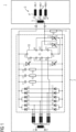
- the representation according to Figure 1 shows a first circuit for a synchronous machine 1.
- the synchronous machine 1 has a stator 3 with stator windings 4, 4 ', 4", a rotor with a rotor winding 5 and an excitation circuit 2.
- the excitation circuit has a resistor 11, in particular a starting resistor .
- the excitation circuit is operated via a control 10 for the excitation.
- the resistance can also be referred to as an additional resistance.
- the rotor winding itself also has a resistance value.
- the additional resistance 11 used in the excitation circuit influences the behavior of the synchronous machine, for example when it starts up or startup. In order to improve the behavior of the synchronous machine, the circuit can be supplemented.
- the basic structure of the circuit in the rotor circuit does not need to be changed significantly. This has the advantage that existing proven components can continue to be used. This is particularly important for: that there are machines without additional resistance or that replicas use the old technology.
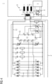
- the representation according to Figure 2 shows an addition to Figure 1 . It is an additional circuit for speed-dependent connection of the additional resistor (RZ) 5 with thyristors 6 and 7 as well as a control logic and a control power part.
- the addition is based on the fact that a bidirectional switch or practically two power electronic unidirectional switches 6 and 7 connected in anti-parallel are arranged parallel to the rotor winding 5. These are a first power semiconductor 6 and a second power semiconductor 7. A control 9 is provided to switch these switches.
- the power semiconductors 6 and 7 are activated in the initial phase of startup.
- thyristors are used in particular, which directly bridge the field winding after ignition.
- the alternating current in the field winding causes it to go out again after a half-wave.
- the components connected in anti-parallel must therefore be activated alternately in order to carry an alternating current.
- the use of thyristors is advantageous because they can cope well with the centrifugal force in the rotor due to their design as a so-called “press pack”.
- Auxiliary energy is required to trigger the switch or to ignite the power electronic components. This is obtained, for example, directly from the voltage induced in the field winding.
- Proven types (T1, T2) from the excitation circuit, with appropriate cooling can be used as thyristors 6 and 6, since the bridging thyristors carry exactly the same current as T1 and T2.
- the bridging should now only take place until a certain speed is reached.
- this signal can be controlled by an external source (telemetry or similar) or, on the other hand, it can be generated directly from the existing voltages/currents on the rotor. This can be done, for example, by measuring the time intervals between the alternating switching of the switches. Since the speed increases during startup and the slip of the rotor decreases accordingly, the switching frequency becomes smaller and smaller. The time intervals are increasing. For example, a timer can now monitor whether a certain minimum time period between switchovers has been exceeded. Is that the case, then switching is suppressed.
- This purely frequency-dependent variant has the advantage that - apart from permissible tolerances of the network frequency - no calculation data subject to uncertainty is included.
- the connection speed can then be varied via bridge configuration/jumper or similar.
- the switchability can have the advantage that the energy conversion in the resistance is reduced without noticeably affecting the effect in terms of torque. This means that the resistance for a specific effect can be made smaller because less thermal capacity has to be provided. This results in particular direct cost advantages, but also indirect advantages, such as lower mass on the rotor, advantages in terms of rotor dynamics, etc.
- the representation according to Figure 3 shows a current flow 8 in the case of activated thyristors 6 and 7.
- the path of the current flow 8 also shows a mesh 8.
- the mesh 8 there is one of the power semiconductors 6 for short-circuiting and the field winding 5, which is to be short-circuited at certain times.
- the representation according to Figure 4 shows a current flow 12 in case of deactivated thyristors 6 and 7.
Abstract
Eine Synchronmaschine (1) weist einen Stator (3) und einen Rotor auf, wobei der Rotor eine Rotorwicklung (5) aufweist, wobei ein erster Leistungshalbleiter (6) zum Kurzschluss der Rotorwicklung (5) vorgesehen ist, wobei der erste Leistungshalbleiter (6) und die Rotorwicklung eine erste Masche (8) ausbilden. Bei einem Verfahren zum Betrieb einer Synchronmaschine (1), wird die Rotorwicklung (5) in einem Betriebszustand der Synchronmaschine (1) kurzgeschlossen, wobei zum Kurzschließen ein erster Kurzschließer (6) verwendet wird, wobei der Kurzschließer (6) und die Rotorwicklung (5) eine erste Masche (8) ausbilden.A synchronous machine (1) has a stator (3) and a rotor, the rotor having a rotor winding (5), a first power semiconductor (6) being provided for short-circuiting the rotor winding (5), the first power semiconductor (6) and the rotor winding forming a first loop (8). In a method for operating a synchronous machine (1), the rotor winding (5) is short-circuited in an operating state of the synchronous machine (1), a first short-circuiter (6) being used for short-circuiting, the short-circuiter (6) and the rotor winding (5) forming a first loop (8).
Description
Die Erfindung betrifft eine Synchronmaschine und ein Verfahren zum Betrieb einer Synchronmaschine.The invention relates to a synchronous machine and a method for operating a synchronous machine.
Um das Drehmoment während des asynchronen Anlaufs von elektrisch erregten Synchronmaschinen zu erhöhen, wird ein Zusatzwiderstand im Rotorstromkreis der Maschine angeordnet. Dieser entfaltet seine größte Wirkung bzgl. des Drehmoments erst bei relativ großen Drehzahlen, wird aber während des gesamten Hochlaufs vom Rotorwicklungswechselstrom durchflossen und ist deshalb großer Verlustleistung ausgesetzt. Entsprechend muss der Widerstand bzgl. seiner thermischen Kapazität dimensioniert werden. Eine derartige Synchronmaschine, welche elektrisch erregt ist, kann auch als fremderregte Synchronmaschine bezeichnet werden. Die Erfindung betrifft auch eine Vorrichtung zum Zuschalten des Rotor-Zusatzwiderstands bei einer elektrisch erregten Synchronmaschine mit asynchronem Anlauf.In order to increase the torque during the asynchronous start-up of electrically excited synchronous machines, an additional resistor is arranged in the machine's rotor circuit. This only develops its greatest effect in terms of torque at relatively high speeds, but the rotor winding alternating current flows through it during the entire run-up and is therefore exposed to large power losses. The resistance must be dimensioned accordingly with regard to its thermal capacity. Such a synchronous machine, which is electrically excited, can also be referred to as a separately excited synchronous machine. The invention also relates to a device for switching on the additional rotor resistance in an electrically excited synchronous machine with asynchronous starting.
Eine Synchronmaschine ist z.B. als ein Schenkelpol-Synchronmotor ausgeführt, welcher einen mit massiven Polen insbesondere ohne Anlaufkäfig ausgeführten Rotor aufweist, wobei diesem Rotor eine schleifringlose Erregermaschine aus einem Stator und einem innerhalb des Stators angeordneten Rotor und einer der Rotorwicklung zugeordneten Gleichrichteranordnung aufweist und der Gleichrichteranordnung elektrisch ein Widerstand, z.B. zur Verringerung eines Pendelmomentes und Erhöhung des Drehmomentes in der Anlaufphase des Synchronmotors, zugeordnet ist. Bei schleifringlos oder auch "bürstenlos" erregten Synchronmotoren, deren Rotor ohne Anlaufkäfig ausgeführt ist, ist es für die Phase des asynchronen Anlaufs üblich, die Feldwicklung über einen äußeren ohmschen Widerstand von ca. dem lOfachen Feldwiderstand kurzzuschließen. Um auch bei erschwerten Anlaufbedingungen eine sicher arbeitende bürstenlose Erregung zu verwirklichen, ist es auch möglich, beim Anlaufvorgang den Gleichrichter entweder kurzzuschließen oder vom Feld zu trennen, wobei das Feld auf einen ohmschen Widerstand (Anlaufwiderstand) geschaltet ist. Durch zusätzliche Maßnahmen kann dieser Widerstand während des synchronen Betriebes abgeschaltet werden.A synchronous machine is designed, for example, as a salient-pole synchronous motor, which has a rotor designed with solid poles, in particular without a starting cage, this rotor having a slip ring-free excitation machine consisting of a stator and a rotor arranged within the stator and a rectifier arrangement assigned to the rotor winding and the rectifier arrangement electrically a resistance, for example to reduce a pendulum torque and increase the torque in the starting phase of the synchronous motor, is assigned. In the case of synchronous motors that are excited without a slip ring or "brushless" and whose rotor is designed without a starting cage, it is common practice for the asynchronous starting phase to short-circuit the field winding via an external ohmic resistance of approximately 10 times the field resistance. To ensure safe operation even under difficult start-up conditions To achieve brushless excitation, it is also possible to either short-circuit the rectifier or disconnect it from the field during the starting process, whereby the field is connected to an ohmic resistance (starting resistance). Additional measures can be used to switch off this resistance during synchronous operation.
Die elektrisch erregte Synchronmaschine hat einen Rotor mit einer Wicklung. Weist der Rotor einen Anlaufwiderstand auf, ist es vorteilhaft, wenn es gelingt, den Widerstand erst ab Erreichen einer gewissen Drehzahl zuzuschalten, dann besteht hinsichtlich seiner Wirkung kein Nachteil, aber ein Vorteil durch den wesentlich geringeren Verlusteintrag. Damit kann der Widerstand kleiner dimensioniert werden, bzw. mit vorhandenen Widerständen, bzw. einem vorhandenen Widerstand können schwerere Anläufe durchgeführt werden. Schwer heißt in diesem Zusammenhang insbesondere auch Anläufe mit hohem Trägheits- und Gegenmoment. Der Widerstand kann mit einem oder einer Vielzahl von Widerstandselementen ausgeführt sein.The electrically excited synchronous machine has a rotor with a winding. If the rotor has a starting resistance, it is advantageous if the resistance can only be switched on once a certain speed has been reached. In this case, there is no disadvantage in terms of its effect, but an advantage due to the significantly lower loss input. This means that the resistance can be dimensioned smaller, or heavier starts can be carried out with existing resistances or an existing resistance. In this context, heavy also means starts with high inertia and counter torque. The resistance can be designed with one or a large number of resistance elements.
Aus der
Wenn es keine Möglichkeit der Zuschaltung des Widerstandes gibt, wird der Widerstand während des Anlaufs dauerhaft im Rotorkreis betrieben und erst im synchronisierten Betrieb der Maschine gebrückt. Diese Brückung erfolgt allerdings nur für eine Stromrichtung, da im synchronisierten Betrieb der Maschine im Rotor ein Gleichstrom fließt, im Gegensatz zum Anlauf, wo in der Rotorwicklung von der induzierten Spannung ein Wechselstrom getrieben wird. Auch eine Schaltung, die einen dauerhaften Betrieb mit Zusatzwiderstand vorsieht, ist möglich, jedoch nachteilig.If there is no possibility of connecting the resistor, the resistor is operated permanently in the rotor circuit during start-up and is only bridged when the machine is in synchronized operation. However, this bridging only takes place for one current direction, since a direct current flows in the rotor when the machine is in synchronized operation, in contrast to start-up, where an alternating current is driven in the rotor winding by the induced voltage. A circuit that provides for permanent operation with an additional resistor is also possible, but disadvantageous.
Eine Aufgabe der Erfindung ist es eine verbesserte Synchronmaschine zu gestalten.One object of the invention is to design an improved synchronous machine.
Eine Lösung der Aufgabe ergibt sich nach den Ansprüchen 1 und 6. Weitere beispielhafte Ausgestaltungen ergeben sich nach den davon abhängigen Ansprüchen 2 bis 5 bzw. 7 bis 9.A solution to the problem results from
Eine Synchronmaschine weist einen Stator und einen Rotor auf, wobei der Rotor eine Rotorwicklung aufweist, wobei ein erster Leistungshalbleiter zum Kurzschluss der Rotorwicklung vorgesehen ist, wobei der erste Leistungshalbleiter und die Rotorwicklung eine erste Masche ausbilden. Eine Masche kann als ein über Zweige geschlossener Umlauf bezeichnet werden. Durch den ersten Leistungshalbleiter kann also die Rotorwicklung kurzgeschlossen werden. Es ergibt sich eine Kurzschlussschaltung. Der erste Leistungshalbleiter ist ein erster Kurzschließer über der Rotorwicklung. Die Masche ist insbesondere frei von einem Anlaufwiderstand der Synchronmaschine. Der erste Leistungshalbleiter ist zumindest ein Teil einer Vorrichtung zum Zuschalten bzw. Wegschalten eines Anlaufwiderstandes, d.h. eines Rotor-Zusatzwiderstands, bei einer elektrisch erregten Synchronmaschine mit asynchronem Anlauf. Die Synchronmaschine weist eine Erregermaschine für die Rotorwicklung auf.A synchronous machine has a stator and a rotor, the rotor having a rotor winding, a first power semiconductor being provided for short-circuiting the rotor winding, the first power semiconductor and the rotor winding forming a first mesh. A mesh can be described as a circuit closed over branches. The rotor winding can therefore be short-circuited by the first power semiconductor. This results in a short-circuit circuit. The first power semiconductor is a first short-circuiter across the rotor winding. The mesh is in particular free of starting resistance of the synchronous machine. The first power semiconductor is at least part of a device for switching on or off a starting resistor, i.e. an additional rotor resistor, in an electrically excited synchronous machine with asynchronous starting. The synchronous machine has an excitation machine for the rotor winding.
In einer Ausgestaltung der Synchronmaschine ist ein zweiter Leistungshalbleiter zum Kurzschluss der Rotorwicklung vorgesehen, wobei der zweite Leistungshalbleiter parallel zum ersten Leistungshalbleiter verschalten ist. So kann in einer weiteren Stromrichtung die Rotorwicklung kurzgeschlossen werden.In one embodiment of the synchronous machine, a second power semiconductor is provided for short-circuiting the rotor winding, the second power semiconductor being connected in parallel to the first power semiconductor. In this way, the rotor winding can be short-circuited in a further current direction.
In einer Ausgestaltung der Synchronmaschine sind die Leistungshalbleiter zum Kurzschluss der Rotorwicklung für unterschiedliche Stromrichtungen in der Rotorwicklung vorgesehen. Hierzu ergeben sich insbesondere Maschen für einen Kurzschlusskreis, welche den Anlaufwiderstand nicht aufweisen, also frei von diesem sind.In one embodiment of the synchronous machine, the power semiconductors for short-circuiting the rotor winding are provided for different current directions in the rotor winding. This results in particular in meshes for a short-circuit circuit which do not have the starting resistance, i.e. are free of it.
In einer Ausgestaltung der Synchronmaschine ist zumindest einer der Leistungshalbleiter ansteuerbar. Hierfür ist eine Ansteuerung vorgesehen. Diese Ansteuerung für die Kurzschließung ermöglicht einen beeinflussbaren Kurzschluss der Rotorwicklung.In one embodiment of the synchronous machine, at least one of the power semiconductors can be controlled. For this purpose, a control This control for the short circuit enables an influenceable short circuit of the rotor winding.
In einer Ausgestaltung der Synchronmaschine sind der zumindest eine erste Leistungshalbleiter und die Rotorwicklung parallel verschalten, wobei dazu ein Anlaufwiderstand seriell verschalten ist. Es gibt also eine weitere Masche, in welcher insbesondere die antiparallel geschaltenen Leistungshalbleiter, der erste Leistungshalbleiter antiparallel zum zweiten Leistungshalbleiter, seriell mit dem Widerstand, insbesondere dem Anlaufwiderstand, verschalten sind.In one embodiment of the synchronous machine, the at least one first power semiconductor and the rotor winding are connected in parallel, with a starting resistor being connected in series. There is therefore a further mesh in which in particular the power semiconductors connected in anti-parallel, the first power semiconductor anti-parallel to the second power semiconductor, are connected in series with the resistor, in particular the starting resistor.
In einem Verfahren zum Betrieb einer Synchronmaschine, wobei die zu betreibende Synchronmaschine einen Stator und einen Rotor aufweist, wobei der Rotor eine Rotorwicklung aufweist, wird die Rotorwicklung in einem Betriebszustand der Synchronmaschine kurzgeschlossen, wobei zum Kurzschließen ein erster Kurzschließer verwendet wird, wobei der Kurzschließer und die Rotorwicklung eine erste Masche ausbilden. Der erste Kurzschließer weist insbesondere den ersten Leistungshalbleiter auf. Antiparallel zum ersten Kurzschließer ist insbesondere ein zweiter Kurzschließer geschalten, welcher den zweiten Leistungshalbleiter aufweist.In a method for operating a synchronous machine, wherein the synchronous machine to be operated has a stator and a rotor, wherein the rotor has a rotor winding, the rotor winding is short-circuited in an operating state of the synchronous machine, wherein a first short-circuiter is used for short-circuiting, wherein the short-circuiter and the rotor winding form a first loop. The first short-circuiter in particular has the first power semiconductor. In particular, a second short-circuiter which has the second power semiconductor is connected antiparallel to the first short-circuiter.
In einer Ausgestaltung des Verfahrens betrifft der Betriebszustand einen Hochlauf und/oder Anlauf der Synchronmaschine. Dies kann einen positiven Effekt auf die Momentenbildung haben.In one embodiment of the method, the operating state relates to a ramp-up and/or start-up of the synchronous machine. This can have a positive effect on torque formation.
In einer Ausgestaltung des Verfahrens wird ein Anlaufwiderstand mit einem dazu parallel verschaltenen zweiten Kurzschließer seriell zur Parallelschaltung von erstem Kurzschließer und Rotorwicklung verschalten. Dies ist eine einfache und kompakte Möglichkeit das Verhalten der Synchronmaschine zu beeinflussen.In one embodiment of the method, a starting resistor with a second short-circuiter connected in parallel is connected in series to the parallel connection of the first short-circuiter and the rotor winding. This is a simple and compact way to influence the behavior of the synchronous machine.
In einer Ausgestaltung des Verfahrens wird eine Synchronmaschine in einer der beschriebenen Ausgestaltungen verwendet.In one embodiment of the method, a synchronous machine in one of the described embodiments is used.
Die Merkmale der einzelnen beanspruchten bzw. beschriebenen Gegenstände sind ohne Weiteres miteinander kombinierbar. Im Folgenden wird die Erfindung beispielhaft anhand von Figuren näher dargestellt und erläutert. Die in den Figuren gezeigten Merkmale können fachmännisch zu neuen Ausführungsformen kombiniert werden, ohne die Erfindung zu verlassen. Es zeigen
- FIG 1
- eine erste Schaltung für eine Synchronmaschine,
- FIG 2
- eine zweite Schaltung für eine Synchronmaschine,
- FIG 3
- eine dritte Schaltung für eine Synchronmaschine und
- FIG 4
- eine vierte Schaltung für eine Synchronmaschine.
- FIG 1
- a first circuit for a synchronous machine,
- FIG 2
- a second circuit for a synchronous machine,
- FIG 3
- a third circuit for a synchronous machine and
- FIG 4
- a fourth circuit for a synchronous machine.
Die Darstellung nach
Die Darstellung nach
Durch die Zuschaltbarkeit kann der Vorteil entstehen, dass der Energieumsatz im Widerstand reduziert wird, ohne die Wirkung bzgl. des Drehmoments spürbar zu beeinträchtigen. Dies zieht nach sich, dass der Widerstand für eine bestimmte Wirkung kleiner ausgeführt werden kann, da weniger thermische Kapazität vorgehalten werden muss. Daraus ergeben sich insbesondere direkte Kostenvorteile, aber auch indirekte Vorteile, wie geringere Masse auf dem Rotor, Vorteile bzgl. der Rotordynamik etc.The switchability can have the advantage that the energy conversion in the resistance is reduced without noticeably affecting the effect in terms of torque. This means that the resistance for a specific effect can be made smaller because less thermal capacity has to be provided. This results in particular direct cost advantages, but also indirect advantages, such as lower mass on the rotor, advantages in terms of rotor dynamics, etc.
Die Darstellung nach
Die Darstellung nach
Claims (9)
Priority Applications (2)
| Application Number | Priority Date | Filing Date | Title |
|---|---|---|---|
| EP22199124.3A EP4346083A1 (en) | 2022-09-30 | 2022-09-30 | Synchronous machine and method for operating a synchronous machine |
| PCT/EP2023/077017 WO2024068908A1 (en) | 2022-09-30 | 2023-09-29 | Synchronous machine and method for operating a synchronous machine |
Applications Claiming Priority (1)
| Application Number | Priority Date | Filing Date | Title |
|---|---|---|---|
| EP22199124.3A EP4346083A1 (en) | 2022-09-30 | 2022-09-30 | Synchronous machine and method for operating a synchronous machine |
Publications (1)
| Publication Number | Publication Date |
|---|---|
| EP4346083A1 true EP4346083A1 (en) | 2024-04-03 |
Family
ID=83546971
Family Applications (1)
| Application Number | Title | Priority Date | Filing Date |
|---|---|---|---|
| EP22199124.3A Pending EP4346083A1 (en) | 2022-09-30 | 2022-09-30 | Synchronous machine and method for operating a synchronous machine |
Country Status (2)
| Country | Link |
|---|---|
| EP (1) | EP4346083A1 (en) |
| WO (1) | WO2024068908A1 (en) |
Citations (3)
| Publication number | Priority date | Publication date | Assignee | Title |
|---|---|---|---|---|
| DE1638126A1 (en) * | 1968-02-17 | 1971-08-26 | Siemens Ag | Device for exciting a synchronous machine |
| DE19934056A1 (en) * | 1999-07-19 | 2001-01-25 | Siemens Ag | Electrical salient pole synchronous motor with slip ringless excitation and starting resistance |
| US20140232317A1 (en) * | 2011-10-24 | 2014-08-21 | Yujing Liu | System And Method For Controlling A Synchronous Motor |
-
2022
- 2022-09-30 EP EP22199124.3A patent/EP4346083A1/en active Pending
-
2023
- 2023-09-29 WO PCT/EP2023/077017 patent/WO2024068908A1/en unknown
Patent Citations (4)
| Publication number | Priority date | Publication date | Assignee | Title |
|---|---|---|---|---|
| DE1638126A1 (en) * | 1968-02-17 | 1971-08-26 | Siemens Ag | Device for exciting a synchronous machine |
| DE19934056A1 (en) * | 1999-07-19 | 2001-01-25 | Siemens Ag | Electrical salient pole synchronous motor with slip ringless excitation and starting resistance |
| US20140232317A1 (en) * | 2011-10-24 | 2014-08-21 | Yujing Liu | System And Method For Controlling A Synchronous Motor |
| US9018888B2 (en) | 2011-10-24 | 2015-04-28 | Abb Technology Ag | System and method for controlling a synchronous motor |
Also Published As
| Publication number | Publication date |
|---|---|
| WO2024068908A1 (en) | 2024-04-04 |
Similar Documents
| Publication | Publication Date | Title |
|---|---|---|
| EP2504918B1 (en) | Preventing load rejection overvoltages in synchronous rectifiers | |
| DE102014105642A1 (en) | Electric machine | |
| DE1964229A1 (en) | Brushless DC motor | |
| DE2305251B2 (en) | EXCITATION DEVICE FOR A SELF-EXCITED ASYNCHRONOUS GENERATOR | |
| DE102017207944A1 (en) | Battery device with at least one module strand, in which module units are connected in a row behind one another, and motor vehicle and operating method for the battery device | |
| DE2457838A1 (en) | AC MOTOR CONTROLLER | |
| EP1670135B1 (en) | Method of operating a rotary electrical machine | |
| DE102013016960A1 (en) | Inverter unit for electric machine has control device to control inverter switches and bridge switches to close, and to cause free-wheel to control one of bridge switches and other inverter switches to open in response to error signal | |
| EP2223426B1 (en) | Method for operating a rotating electric machine | |
| DE2821020A1 (en) | METHOD AND DEVICE FOR DRIVING A STEPPER MOTOR | |
| EP0771065B1 (en) | Start-up method for a rotating variable speed electrical drive | |
| EP2034606B1 (en) | Method for operating an electric rotary machine | |
| DE102014208747A1 (en) | Method for changing an operating state of an electrical machine and device for changing the operating state of an electrical machine | |
| EP0059245B1 (en) | Part-winding starting circuit for three-phase motors | |
| DE2829685C2 (en) | Motor fed by DC voltage | |
| EP4346083A1 (en) | Synchronous machine and method for operating a synchronous machine | |
| EP2117108B1 (en) | Method for starting a system for generating electrical energy | |
| EP3913791A1 (en) | Multi-system motor for connection to an ac or dc voltage network | |
| DE2239396A1 (en) | MULTI-PHASE THYRISTOR INVERTER WITH FORCED COMPUTATION | |
| DE102013208067A1 (en) | Polyphase electrical circuit | |
| DE602557C (en) | Device for maintaining stable operation and regulating the voltage of electrical machines in the event of sudden changes in load | |
| DE2530259C3 (en) | Speed-adjustable arrangement with a single-phase commutator motor | |
| DE1538346C (en) | Power supply system for approximately constant frequency | |
| DE261995C (en) | ||
| DE1538346B2 (en) | POWER SUPPLY SYSTEM FOR ABOUT CONSTANT FREQUENCY |
Legal Events
| Date | Code | Title | Description |
|---|---|---|---|
| PUAI | Public reference made under article 153(3) epc to a published international application that has entered the european phase |
Free format text: ORIGINAL CODE: 0009012 |
|
| STAA | Information on the status of an ep patent application or granted ep patent |
Free format text: STATUS: THE APPLICATION HAS BEEN PUBLISHED |
|
| AK | Designated contracting states |
Kind code of ref document: A1 Designated state(s): AL AT BE BG CH CY CZ DE DK EE ES FI FR GB GR HR HU IE IS IT LI LT LU LV MC MK MT NL NO PL PT RO RS SE SI SK SM TR |