EP4345883A1 - Semiconductor device with active mold package and method therefor - Google Patents
Semiconductor device with active mold package and method therefor Download PDFInfo
- Publication number
- EP4345883A1 EP4345883A1 EP23198548.2A EP23198548A EP4345883A1 EP 4345883 A1 EP4345883 A1 EP 4345883A1 EP 23198548 A EP23198548 A EP 23198548A EP 4345883 A1 EP4345883 A1 EP 4345883A1
- Authority
- EP
- European Patent Office
- Prior art keywords
- encapsulant
- conductive
- trace
- die
- conductive trace
- Prior art date
- Legal status (The legal status is an assumption and is not a legal conclusion. Google has not performed a legal analysis and makes no representation as to the accuracy of the status listed.)
- Pending
Links
- 239000004065 semiconductor Substances 0.000 title claims abstract description 135
- 238000000034 method Methods 0.000 title claims abstract description 41
- 239000008393 encapsulating agent Substances 0.000 claims abstract description 144
- 230000004913 activation Effects 0.000 claims abstract description 25
- 239000004020 conductor Substances 0.000 claims abstract description 14
- 238000007747 plating Methods 0.000 claims abstract description 13
- 239000000758 substrate Substances 0.000 claims description 49
- 229910000679 solder Inorganic materials 0.000 claims description 13
- 238000001465 metallisation Methods 0.000 claims description 11
- 239000000463 material Substances 0.000 claims description 6
- 238000000151 deposition Methods 0.000 claims description 2
- 238000004519 manufacturing process Methods 0.000 description 36
- 238000007772 electroless plating Methods 0.000 description 11
- 238000004806 packaging method and process Methods 0.000 description 11
- RYGMFSIKBFXOCR-UHFFFAOYSA-N Copper Chemical compound [Cu] RYGMFSIKBFXOCR-UHFFFAOYSA-N 0.000 description 10
- 229910052802 copper Inorganic materials 0.000 description 10
- 239000010949 copper Substances 0.000 description 10
- 229920006336 epoxy molding compound Polymers 0.000 description 9
- 238000000608 laser ablation Methods 0.000 description 7
- 239000000654 additive Substances 0.000 description 6
- 230000000996 additive effect Effects 0.000 description 6
- 239000000126 substance Substances 0.000 description 5
- PCHJSUWPFVWCPO-UHFFFAOYSA-N gold Chemical compound [Au] PCHJSUWPFVWCPO-UHFFFAOYSA-N 0.000 description 4
- 229910052737 gold Inorganic materials 0.000 description 4
- 239000010931 gold Substances 0.000 description 4
- 238000000465 moulding Methods 0.000 description 4
- 239000002923 metal particle Substances 0.000 description 3
- 230000003213 activating effect Effects 0.000 description 2
- 239000003054 catalyst Substances 0.000 description 2
- PWGQHOJABIQOOS-UHFFFAOYSA-N copper;dioxido(dioxo)chromium Chemical compound [Cu+2].[O-][Cr]([O-])(=O)=O PWGQHOJABIQOOS-UHFFFAOYSA-N 0.000 description 2
- 238000001746 injection moulding Methods 0.000 description 2
- 238000012986 modification Methods 0.000 description 2
- 230000004048 modification Effects 0.000 description 2
- 229920002577 polybenzoxazole Polymers 0.000 description 2
- JBRZTFJDHDCESZ-UHFFFAOYSA-N AsGa Chemical compound [As]#[Ga] JBRZTFJDHDCESZ-UHFFFAOYSA-N 0.000 description 1
- 229910002601 GaN Inorganic materials 0.000 description 1
- 229910001218 Gallium arsenide Inorganic materials 0.000 description 1
- JMASRVWKEDWRBT-UHFFFAOYSA-N Gallium nitride Chemical compound [Ga]#N JMASRVWKEDWRBT-UHFFFAOYSA-N 0.000 description 1
- 239000004642 Polyimide Substances 0.000 description 1
- XUIMIQQOPSSXEZ-UHFFFAOYSA-N Silicon Chemical compound [Si] XUIMIQQOPSSXEZ-UHFFFAOYSA-N 0.000 description 1
- 238000006243 chemical reaction Methods 0.000 description 1
- 230000003203 everyday effect Effects 0.000 description 1
- 238000009472 formulation Methods 0.000 description 1
- 229910052732 germanium Inorganic materials 0.000 description 1
- GNPVGFCGXDBREM-UHFFFAOYSA-N germanium atom Chemical compound [Ge] GNPVGFCGXDBREM-UHFFFAOYSA-N 0.000 description 1
- 230000015654 memory Effects 0.000 description 1
- 239000000203 mixture Substances 0.000 description 1
- 229920001721 polyimide Polymers 0.000 description 1
- 239000002861 polymer material Substances 0.000 description 1
- 238000012913 prioritisation Methods 0.000 description 1
- 229910052710 silicon Inorganic materials 0.000 description 1
- 239000010703 silicon Substances 0.000 description 1
- 239000000243 solution Substances 0.000 description 1
- 230000002123 temporal effect Effects 0.000 description 1
Images


Classifications
-
- H—ELECTRICITY
- H01—ELECTRIC ELEMENTS
- H01L—SEMICONDUCTOR DEVICES NOT COVERED BY CLASS H10
- H01L24/00—Arrangements for connecting or disconnecting semiconductor or solid-state bodies; Methods or apparatus related thereto
- H01L24/01—Means for bonding being attached to, or being formed on, the surface to be connected, e.g. chip-to-package, die-attach, "first-level" interconnects; Manufacturing methods related thereto
- H01L24/18—High density interconnect [HDI] connectors; Manufacturing methods related thereto
- H01L24/19—Manufacturing methods of high density interconnect preforms
-
- H—ELECTRICITY
- H01—ELECTRIC ELEMENTS
- H01L—SEMICONDUCTOR DEVICES NOT COVERED BY CLASS H10
- H01L21/00—Processes or apparatus adapted for the manufacture or treatment of semiconductor or solid state devices or of parts thereof
- H01L21/02—Manufacture or treatment of semiconductor devices or of parts thereof
- H01L21/04—Manufacture or treatment of semiconductor devices or of parts thereof the devices having potential barriers, e.g. a PN junction, depletion layer or carrier concentration layer
- H01L21/48—Manufacture or treatment of parts, e.g. containers, prior to assembly of the devices, using processes not provided for in a single one of the subgroups H01L21/06 - H01L21/326
- H01L21/4814—Conductive parts
- H01L21/4846—Leads on or in insulating or insulated substrates, e.g. metallisation
- H01L21/4853—Connection or disconnection of other leads to or from a metallisation, e.g. pins, wires, bumps
-
- H—ELECTRICITY
- H01—ELECTRIC ELEMENTS
- H01L—SEMICONDUCTOR DEVICES NOT COVERED BY CLASS H10
- H01L21/00—Processes or apparatus adapted for the manufacture or treatment of semiconductor or solid state devices or of parts thereof
- H01L21/02—Manufacture or treatment of semiconductor devices or of parts thereof
- H01L21/04—Manufacture or treatment of semiconductor devices or of parts thereof the devices having potential barriers, e.g. a PN junction, depletion layer or carrier concentration layer
- H01L21/48—Manufacture or treatment of parts, e.g. containers, prior to assembly of the devices, using processes not provided for in a single one of the subgroups H01L21/06 - H01L21/326
- H01L21/4814—Conductive parts
- H01L21/4846—Leads on or in insulating or insulated substrates, e.g. metallisation
- H01L21/4857—Multilayer substrates
-
- H—ELECTRICITY
- H01—ELECTRIC ELEMENTS
- H01L—SEMICONDUCTOR DEVICES NOT COVERED BY CLASS H10
- H01L21/00—Processes or apparatus adapted for the manufacture or treatment of semiconductor or solid state devices or of parts thereof
- H01L21/02—Manufacture or treatment of semiconductor devices or of parts thereof
- H01L21/04—Manufacture or treatment of semiconductor devices or of parts thereof the devices having potential barriers, e.g. a PN junction, depletion layer or carrier concentration layer
- H01L21/50—Assembly of semiconductor devices using processes or apparatus not provided for in a single one of the subgroups H01L21/06 - H01L21/326, e.g. sealing of a cap to a base of a container
- H01L21/56—Encapsulations, e.g. encapsulation layers, coatings
- H01L21/565—Moulds
-
- H—ELECTRICITY
- H01—ELECTRIC ELEMENTS
- H01L—SEMICONDUCTOR DEVICES NOT COVERED BY CLASS H10
- H01L23/00—Details of semiconductor or other solid state devices
- H01L23/28—Encapsulations, e.g. encapsulating layers, coatings, e.g. for protection
- H01L23/31—Encapsulations, e.g. encapsulating layers, coatings, e.g. for protection characterised by the arrangement or shape
- H01L23/3107—Encapsulations, e.g. encapsulating layers, coatings, e.g. for protection characterised by the arrangement or shape the device being completely enclosed
- H01L23/3121—Encapsulations, e.g. encapsulating layers, coatings, e.g. for protection characterised by the arrangement or shape the device being completely enclosed a substrate forming part of the encapsulation
- H01L23/3128—Encapsulations, e.g. encapsulating layers, coatings, e.g. for protection characterised by the arrangement or shape the device being completely enclosed a substrate forming part of the encapsulation the substrate having spherical bumps for external connection
-
- H—ELECTRICITY
- H01—ELECTRIC ELEMENTS
- H01L—SEMICONDUCTOR DEVICES NOT COVERED BY CLASS H10
- H01L23/00—Details of semiconductor or other solid state devices
- H01L23/52—Arrangements for conducting electric current within the device in operation from one component to another, i.e. interconnections, e.g. wires, lead frames
- H01L23/538—Arrangements for conducting electric current within the device in operation from one component to another, i.e. interconnections, e.g. wires, lead frames the interconnection structure between a plurality of semiconductor chips being formed on, or in, insulating substrates
- H01L23/5383—Multilayer substrates
-
- H—ELECTRICITY
- H01—ELECTRIC ELEMENTS
- H01L—SEMICONDUCTOR DEVICES NOT COVERED BY CLASS H10
- H01L23/00—Details of semiconductor or other solid state devices
- H01L23/52—Arrangements for conducting electric current within the device in operation from one component to another, i.e. interconnections, e.g. wires, lead frames
- H01L23/538—Arrangements for conducting electric current within the device in operation from one component to another, i.e. interconnections, e.g. wires, lead frames the interconnection structure between a plurality of semiconductor chips being formed on, or in, insulating substrates
- H01L23/5386—Geometry or layout of the interconnection structure
-
- H—ELECTRICITY
- H01—ELECTRIC ELEMENTS
- H01L—SEMICONDUCTOR DEVICES NOT COVERED BY CLASS H10
- H01L23/00—Details of semiconductor or other solid state devices
- H01L23/52—Arrangements for conducting electric current within the device in operation from one component to another, i.e. interconnections, e.g. wires, lead frames
- H01L23/538—Arrangements for conducting electric current within the device in operation from one component to another, i.e. interconnections, e.g. wires, lead frames the interconnection structure between a plurality of semiconductor chips being formed on, or in, insulating substrates
- H01L23/5389—Arrangements for conducting electric current within the device in operation from one component to another, i.e. interconnections, e.g. wires, lead frames the interconnection structure between a plurality of semiconductor chips being formed on, or in, insulating substrates the chips being integrally enclosed by the interconnect and support structures
-
- H—ELECTRICITY
- H01—ELECTRIC ELEMENTS
- H01L—SEMICONDUCTOR DEVICES NOT COVERED BY CLASS H10
- H01L24/00—Arrangements for connecting or disconnecting semiconductor or solid-state bodies; Methods or apparatus related thereto
- H01L24/01—Means for bonding being attached to, or being formed on, the surface to be connected, e.g. chip-to-package, die-attach, "first-level" interconnects; Manufacturing methods related thereto
- H01L24/18—High density interconnect [HDI] connectors; Manufacturing methods related thereto
- H01L24/20—Structure, shape, material or disposition of high density interconnect preforms
-
- H—ELECTRICITY
- H01—ELECTRIC ELEMENTS
- H01L—SEMICONDUCTOR DEVICES NOT COVERED BY CLASS H10
- H01L2224/00—Indexing scheme for arrangements for connecting or disconnecting semiconductor or solid-state bodies and methods related thereto as covered by H01L24/00
- H01L2224/01—Means for bonding being attached to, or being formed on, the surface to be connected, e.g. chip-to-package, die-attach, "first-level" interconnects; Manufacturing methods related thereto
- H01L2224/18—High density interconnect [HDI] connectors; Manufacturing methods related thereto
- H01L2224/20—Structure, shape, material or disposition of high density interconnect preforms
- H01L2224/21—Structure, shape, material or disposition of high density interconnect preforms of an individual HDI interconnect
- H01L2224/214—Connecting portions
-
- H—ELECTRICITY
- H01—ELECTRIC ELEMENTS
- H01L—SEMICONDUCTOR DEVICES NOT COVERED BY CLASS H10
- H01L2924/00—Indexing scheme for arrangements or methods for connecting or disconnecting semiconductor or solid-state bodies as covered by H01L24/00
- H01L2924/30—Technical effects
- H01L2924/35—Mechanical effects
- H01L2924/351—Thermal stress
Definitions
- This disclosure relates generally to semiconductor device packaging, and more specifically, to semiconductor devices with active mold packaging and method of forming the same.
- a semiconductor device with active mold packaging includes encapsulants formulated for selective activation by way of a laser in a laser direct structuring process.
- the semiconductor device includes a core encapsulant at least partially encapsulating a semiconductor die and a package substrate formed on a major surface of the core encapsulated semiconductor die.
- the package substrate is formed as a build-up package substrate and includes plated conductive traces separated by one or more encapsulant layers.
- the core encapsulant and each of the one or more encapsulant layers of the package substrate are epoxy molding compounds which include a chemical additive that forms metal particles when activated by way of a laser.
- First conductive traces of the package substrate are formed by way of a plating process utilizing activated patterned paths on the major surface.
- the first conductive traces are interconnected to die pads of the semiconductor die.
- a subsequent encapsulant layer of the package substrate is formed over the first conductive traces and exposed portions of the major surface. Openings through the subsequent encapsulant and patterned paths are formed using laser ablation thus activating the first encapsulant at the sidewalls of the openings and along the patterned paths.
- Second conductive traces of the package substrate are formed by way of a plating process utilizing activated openings sidewalls and patterned paths of the subsequent encapsulant.
- the second conductive traces are interconnected to first conductive traces by way of a via portion of the second conductive traces.
- the via portion may be configured as an under-bump metallization for subsequent attachment of solder balls.
- FIG. 1 illustrates, in a simplified cross-sectional view, an example semiconductor device 100 having active mold packaging at a stage of manufacture in accordance with an embodiment.
- the semiconductor device 100 includes a semiconductor wafer 110 having an active side encapsulated with an encapsulant 108.
- the semiconductor wafer 110 includes a plurality of semiconductor die 102 (sites) separated from one another by singulation lanes 106 illustrated by dashed lines.
- the encapsulant 108 is formulated for selective activation by way of a laser.
- the encapsulant 108 e.g., epoxy molding compound
- includes a chemical additive e.g., copper chromate
- a chemical reaction is initiated causing the activated portion of the encapsulant to form metal particles sufficient to serve as a seed layer for electroless plating (e.g., copper).
- Each of the semiconductor die 102 has an active side (e.g., major side having circuitry) and a backside (e.g., major side opposite of the active side).
- the semiconductor die 102 includes die pads 104 formed at the active side. Die pads 104 may be configured for connection to a package substrate by way of conductive die connectors formed at a subsequent stage, for example.
- the term "conductive,” as used herein, generally refers to electrical conductivity unless otherwise specified.
- the plurality of semiconductor die 102 is configured in an active-side-up orientation with the encapsulant 108 formed over the active side of the wafer 110.
- the semiconductor wafer 110 may be formed from any suitable semiconductor material, such as silicon, germanium, gallium arsenide, gallium nitride, and the like.
- Each of the semiconductor die 102 may further include digital circuits, analog circuits, RF circuits, power circuits, memories, processors, the like, and combinations thereof at the active side.
- FIG. 2 illustrates, in a simplified cross-sectional view, the example semiconductor device 100 at a subsequent stage of manufacture in accordance with an embodiment.
- the semiconductor device 100 includes openings 202 formed through the encapsulant 108 by way of a laser.
- the through encapsulant openings 202 expose predetermined portions of the die pads 104 of the plurality of semiconductor die 102.
- the additive of the encapsulant 108 is activated at the sidewalls causing a thin conductive lining (not shown) to be formed in the openings.
- the thin conductive linings formed in the openings 202 of the encapsulant 108 serve as a catalyst (e.g., seed layer) for electroless plating at a subsequent stage of manufacture.
- FIG. 3 illustrates, in a simplified cross-sectional view, the example semiconductor device 100 at a subsequent stage of manufacture in accordance with an embodiment.
- the semiconductor device 100 includes a plurality of conductive die connectors 302 formed in the respective openings 202 of FIG. 2 .
- the conductive die connectors 302 are formed by substantially filling the through encapsulant openings 202 with a plated conductive material (e.g., copper).
- the encapsulated wafer 110 is subjected to an electroless plating operation by utilizing the thin conductive linings formed on the activated sidewalls as seed layers.
- a first end of the conductive die connectors 302 are conductively connected to the exposed die pads 104 of the plurality of semiconductor die 102 by way of the plating operation.
- FIG. 4 illustrates, in a simplified cross-sectional view, the example semiconductor device 100 at a subsequent stage of manufacture in accordance with an embodiment.
- the semiconductor device 100 includes a singulated semiconductor die 102 and corresponding portion of the encapsulant 108 formed on the active side.
- the encapsulated semiconductor die 102 is reconfigured in an active-side-down orientation and placed on a carrier substrate 402. In this configuration, a major surface of the encapsulant 108 and exposed second ends of the conductive die connectors 302 are temporarily affixed to the carrier substrate 402.
- FIG. 5 illustrates, in a simplified cross-sectional view, the example semiconductor device 100 at a subsequent stage of manufacture in accordance with an embodiment.
- the semiconductor device 100 includes the singulated semiconductor die 102 and portion of the encapsulant 108 encapsulated with a second encapsulant 502.
- the encapsulant 502 is an epoxy molding compound formulated for selective activation by way of a laser in a laser direct structuring process.
- the singulated semiconductor die 102 and portion of the encapsulant 108 are over-molded with the encapsulant 502 by way of a molding process (e.g., injection molding).
- the encapsulant 502 encapsulates the backside and sidewalls of the semiconductor die 102 and sidewalls of the encapsulant 108.
- the encapsulated semiconductor device 100 at this stage includes a first major surface 504 (e.g., top surface) and a second major surface 506 (e.g., opposite major surface) temporarily affixed to the carrier substrate 402.
- FIG. 6 illustrates, in a simplified cross-sectional view, the example semiconductor device 100 at a subsequent stage of manufacture in accordance with an embodiment.
- the semiconductor device 100 includes patterned paths formed by way of a laser 602 at the major surface 506.
- the encapsulated semiconductor device 100 is separated from the carrier substrate 402 of FIG. 5 and reconfigured (e.g., flipped) in a bottom-side-up orientation.
- the second ends of the conductive die connectors 302 are exposed through the encapsulant 108 at the major surface 506.
- the patterned paths at the major surface 506 are formed by way of laser ablation causing portions of the encapsulants 108 and 502 to be activated along the paths.
- the resulting thin conductive patterned paths formed at the major surface 506 serve as a catalyst (e.g., seed layer) for electroless plating at a subsequent stage of manufacture.
- the major surface 506 includes surfaces of the encapsulants 108 and 502 and second ends of the conductive die connectors 302 substantially coplanar.
- FIG. 7 illustrates, in a simplified cross-sectional view, the example semiconductor device 100 at a subsequent stage of manufacture in accordance with an embodiment.
- the semiconductor device 100 includes conductive traces 702 formed on the activated patterned paths at the major surface 506.
- the semiconductor device 100 is subjected to an electroless plating operation to form a plated conductive material layer (e.g., copper) on the activated patterned paths and exposed portions of the conductive die connectors 302.
- the formed conductive traces 702 are conductively connected to the second ends of the conductive die connectors 302 and provide an interconnection to the die pads 104 of the semiconductor die 102 by way of the conductive die connectors 302.
- the formed conductive traces 702 serve as a first interconnect layer of a build-up package substrate characterized as a build-up redistribution layer (RDL) type package substrate.
- RDL redistribution layer
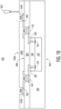
- FIG. 8 illustrates, in a simplified cross-sectional view, the example semiconductor device 100 at a subsequent stage of manufacture in accordance with an embodiment.
- the semiconductor device 100 includes the conductive traces 702 and exposed portions of the major surface 506 encapsulated with a third encapsulant 802.
- the encapsulant 802 is an epoxy molding compound formulated for selective activation by way of a laser in a laser direct structuring process.
- the conductive traces 702 and exposed portions of the major surface 506 are over-molded with the encapsulant 802 by way of a molding process.
- openings 804 and patterned paths are formed by way of the laser 602 at a major surface 806 of the encapsulant 802.
- the through encapsulant openings 804 expose predetermined portions of the conductive traces 702.
- thin conductive linings are formed at the sidewalls 808 of the openings and along the patterned paths at the major surface 806 of the encapsulant 802.
- the activated sidewalls 808 and activated patterned paths serve as a seed layer for electroless plating at a subsequent stage of manufacture.
- the encapsulant 502 may be formulated without the aforementioned laser activated chemical additive while maintaining compatible mechanical properties such as coefficient of thermal expansion. Accordingly, the steps depicted in FIG. 6 and FIG. 7 may be omitted such that the encapsulant 802 encapsulates the major surface 506 and the through encapsulant openings 804 are located to expose predetermined portions of the second ends of the conductive die connectors 302. Conductive traces formed at a subsequent stage may be configured with a via (e.g., vertical) portion formed on sidewalls 808 of respective openings 804 to provide a direct connection to the die connectors 302.
- a via e.g., vertical
- FIG. 9 illustrates, in a simplified cross-sectional view, the example semiconductor device 100 at a subsequent stage of manufacture in accordance with an embodiment.
- the semiconductor device 100 includes conductive traces 902 formed on the activated sidewalls 808 of the openings 804 and activated patterned paths at the major surface 806.
- the semiconductor device 100 is subjected to an electroless plating operation to form a plated conductive material layer (e.g., copper) on the activated sidewalls 808, patterned paths, and exposed portions of the conductive traces 702.
- a plated conductive material layer e.g., copper
- Each of the conductive traces 902 is configured having a via (e.g., vertical) portion formed on sidewalls 808 of respective openings 804 and a lateral (e.g., horizontal) portion that extends laterally along a portion of the major surface 806 of the encapsulant 802.
- the via portion is configured to provide a vertical interconnection between the lateral portion of the conductive traces 902 and respective underlying conductive traces 702.
- the formed conductive traces 902 are configured to serve as a second interconnect layer of the build-up package substrate with the encapsulant 802 configured to serve as a dielectric layer of the package substrate.
- FIG. 10 illustrates, in a simplified cross-sectional view, the example semiconductor device 100 at a subsequent stage of manufacture in accordance with an embodiment.
- the semiconductor device 100 includes the conductive traces 902, openings 804, and exposed portions of the major surface 806 encapsulated with a fourth encapsulant 1002.
- the encapsulant 1002 is an epoxy molding compound formulated for selective activation by way of a laser in a laser direct structuring process.
- the conductive traces 902 and exposed portions of the major surface 806 are over-molded with the encapsulant 1002 by way of a molding process.
- openings 1004 are formed by way of the laser 602 at a major surface 1006 of the encapsulant 1002.
- the through encapsulant openings 1004 expose predetermined portions of the conductive traces 902. By forming the openings 1004 by way of laser ablation, thin conductive linings are formed at the sidewalls 1008 of the openings 1004.
- the activated sidewalls 1008 and activated patterned paths serve as a seed layer for electroless plating at a subsequent stage of manufacture.
- FIG. 11 illustrates, in a simplified cross-sectional view, the example semiconductor device 100 at a subsequent stage of manufacture in accordance with an embodiment.
- the semiconductor device 100 includes conductive traces 1102 formed on the activated sidewalls 1008 of the openings 1004 and activated patterned paths at the major surface 1006.
- the semiconductor device 100 is subjected to an electroless plating operation to form a plated conductive material layer (e.g., copper) on the activated sidewalls 1008 and exposed portions of the conductive traces 902.
- a plated conductive material layer e.g., copper
- Each of the conductive traces 1102 is configured as an under-bump metallization suitable for attachment of a conductive connector (e.g., solder ball) at a subsequent stage of manufacture.
- Each of the conductive traces 1102 are interconnected to respective die pads 104 by way of die connectors 302 and traces 702 and 902 of the package substrate, for example.
- FIG. 12 illustrates, in a simplified cross-sectional view, the example semiconductor device 100 at a subsequent stage of manufacture in accordance with an embodiment.
- the semiconductor device 100 includes conductive connectors 1202 affixed to respective conductive traces 1102 configured as under-bump metallization.
- the semiconductor device 100 is reconfigured in a bottom-side-down orientation for illustration purposes.
- the conductive connectors 1202 may be in the form of suitable conductive structures such as solder balls, gold studs, copper pillars, and the like, to connect conductive features of the package substrate 1204 with a printed circuit board (PCB), for example.
- PCB printed circuit board
- the exposed portions of conductive traces 1102 may be plated for subsequent connection with the PCB by way of solder paste attachment or other suitable conductive attachment processes (e.g., ACF, ACP).
- each of the encapsulants 108 and 502 (e.g., encapsulating the semiconductor die 102) have a substantially similar formulation as each of the encapsulants 802 and 1002 of the package substrate 1204.
- each of the encapsulants 108, 502, 802, and 1002 is an epoxy molding compound which includes a chemical additive (e.g., copper chromate) capable of being activated by way of a laser (e.g., in a laser direct structuring process).
- a chemical additive e.g., copper chromate
- a laser e.g., in a laser direct structuring process
- FIG. 13 through FIG. 15 illustrate, in simplified cross-sectional views, the example semiconductor device 100 at alternative stages of manufacture in accordance with an embodiment.
- the stages of manufacture depicted in FIG. 13 through FIG. 15 are an alternative to the stages of manufacture of the example semiconductor device 100 depicted in FIG. 1 through FIG. 5 .
- FIG. 13 illustrates, in a simplified cross-sectional view, the example semiconductor device 100 at an alternative stage of manufacture in accordance with an embodiment.
- the example semiconductor device 100 includes conductive stud bumps 1302 formed on respective die pads 104 of the plurality of semiconductor die 102 (sites) of the semiconductor wafer 110.
- singulation lanes 106 illustrated a by dashed lines separate the semiconductor die 102 from one another.
- the stud bumps 1302 may be formed from copper, gold, or solder.
- FIG. 14 illustrates, in a simplified cross-sectional view, the example semiconductor device 100 at a subsequent stage of manufacture in accordance with an embodiment.
- the semiconductor device 100 includes a singulated semiconductor die 102 and corresponding stud bumps 1302 formed on die pads 104 at the active side.
- the semiconductor die 102 with attached stud bumps 1302 is reconfigured in an active-side-down orientation and placed on a carrier substrate 1402. In this configuration, a first end of each stud bump 1302 is attached to a respective die pad 104 and a second end of each stud bump 1302 is temporarily affixed to a carrier substrate 1402.
- FIG. 15 illustrates, in a simplified cross-sectional view, the example semiconductor device 100 at a subsequent stage of manufacture in accordance with an embodiment.
- the semiconductor die 102 with attached stud bumps 1302 is encapsulated with an encapsulant 1502 while temporarily affixed to the carrier substrate 1402.
- the encapsulant 1502 is an epoxy molding compound formulated for selective activation by way of a laser in a laser direct structuring process.
- the singulated semiconductor die 102 and stud bumps 1302 are over-molded with the encapsulant 1502 by way of a molding process (e.g., injection molding).
- the encapsulant 1502 encapsulates the backside, sidewalls, and most of the active side of the semiconductor die 102.
- the encapsulated semiconductor device 100 at this stage includes a first major surface 1504 (e.g., top surface) and a second major surface 1506 (e.g., opposite major surface) temporarily affixed to the carrier substrate 1402. Subsequent stages of manufacture remain substantially similar as depicted in FIG. 6 through FIG. 12 .
- FIG. 16 illustrates, in a simplified cross-sectional view, an alternative example semiconductor device 1600 having active mold packaging at a stage of manufacture in accordance with an embodiment.
- the stage of manufacture depicted in FIG. 16 is an alternative to the stages of manufacture of the example semiconductor device 100 depicted in FIG. 7 through FIG. 12 with the stages of manufacture depicted in FIG. 1 through FIG. 6 remaining substantially similar.
- the semiconductor device 1600 is reconfigured in a bottom-side-down orientation for illustration purposes.
- the semiconductor device 1600 includes an alternative package substrate 1610 formed on the major surface 506.
- conductive traces 1602 e.g., copper
- the plated conductive traces 1602 are interconnected to the die pads 104 of the semiconductor die 102 by way of the conductive die connectors 302.
- the conductive traces 1602 serve as an interconnect layer of the package substrate 1610 characterized as a build-up RDL type package substrate.
- the conductive traces 1602 of the package substrate 1610 and exposed portions of the major surface 506 are encapsulated with an encapsulant 1604.
- the encapsulant 1604 is an epoxy molding compound formulated for selective activation by way of a laser in a laser direct structuring process.
- the encapsulant 1604 is configured to serve as a dielectric layer of the package substrate 1610, for example.
- openings are formed through the encapsulant 1604 by way of laser ablation to expose predetermined portions of the conductive traces 1602.
- the activated sidewalls 1606 serve as a seed layer for electroless plating to form conductive traces 1608.
- Conductive traces 1608 are configured as under-bump metallization structures of the package substrate 1610.
- Conductive connectors 1612 are affixed to respective conductive traces 1608.
- the conductive connectors 1612 may be in the form of suitable conductive structures such as solder balls, gold studs, copper pillars, and the like, to connect conductive features of the package substrate 1610 with a PCB, for example.
- FIG. 17 illustrates, in a simplified cross-sectional view, an alternative example semiconductor device1700 having active mold packaging at a stage of manufacture in accordance with an embodiment.
- the stage of manufacture depicted in FIG. 17 is an alternative to the stages of manufacture of the example semiconductor device 100 depicted in FIG. 10 through FIG. 12 with the stages of manufacture depicted in FIG. 1 through FIG. 9 remaining substantially similar.
- the semiconductor device 1700 is reconfigured in a bottom-side-down orientation for illustration purposes.
- the semiconductor device 1700 includes an alternative package substrate 1706 formed on the major surface 506.
- the package substrate 1706 may be characterized as a build-up RDL type package substrate.
- a non-conductive layer 1702 is applied or otherwise deposited on the conductive traces 902, openings 804 ( FIG. 8 ), and exposed portions of the major surface 806.
- the non-conductive layer 1702 may be formed from suitable non-conducting materials such as polybenzoxazole (PBO), polyimide, and Ajinomoto build-up film (ABF), for example.
- the non-conductive layer 1702 is characterized as a photo-imageable polymer material (e.g., photosensitive solder mask material) film. Openings are formed through the non-conductive layer 1702 to expose predetermined portions of the conductive traces 902. Conductive connectors 1708 are affixed to respective exposed portions of conductive traces 902 through the openings.
- the conductive connectors 1708 may be in the form of suitable conductive structures such as solder balls, gold studs, copper pillars, and the like, to connect conductive features of the package substrate 1706 with a PCB, for example.
- a method of forming a semiconductor device including forming a conductive die connector having a first end connected to a die pad of a semiconductor die; encapsulating with a first encapsulant at least a portion of the semiconductor die, the first encapsulant formulated for selective activation by way of a laser; forming a first conductive trace of a redistribution layer by plating a conductive material on a first laser activated path on a first major surface of the first encapsulant, the first conductive trace directly connected to a second end of the die connector; and encapsulating with a second encapsulant at least the first conductive trace and exposed portions of the first major surface of the first encapsulant, the second encapsulant formulated for selective activation by way of a laser.
- the method may further include forming a first opening in the second encapsulant, the first opening exposing a predetermined portion of the first conductive trace, the second encapsulant activated at the sidewalls of the first opening; and forming a second conductive trace of the redistribution layer by plating the conductive material on the activated sidewalls of the first opening and exposed portion of the first conductive trace.
- the second conductive trace may be configured as an under-bump metallization structure.
- the method may further include affixing a conductive connector to the second conductive trace.
- the second conductive trace may be configured as a via connected to the first conductive trace and a portion of the second conductive trace may be extended laterally along a portion of a major surface of second encapsulant.
- the method may further include encapsulating with a third encapsulant at least the second conductive trace and exposed portions of the major surface of the second encapsulant, the third encapsulant formulated for selective activation by way of the laser; forming a second opening in the third encapsulant, the second opening exposing a predetermined portion of the extended portion of the second conductive trace, the third encapsulant activated at the sidewalls of the second opening; and forming a third conductive trace of the redistribution layer by plating the conductive material on the activated sidewalls of the second opening and exposed portion of the second conductive trace.
- the method may further include affixing a conductive connector to the third conductive trace, the third conductive trace configured as an under-bump metallization structure.
- the method may further include depositing a solder mask material over the second conductive trace and exposed portions of the second encapsulant; and forming an opening in the solder mask material, the opening exposing a predetermined portion of the second conductive trace.
- the method may further include affixing a conductive connector to the exposed portion of the second conductive trace.
- a method of forming a semiconductor device including forming a conductive die connector having a first end connected to a die pad of a semiconductor die; encapsulating with a first encapsulant at least a portion of the semiconductor die, the first encapsulant formulated for selective activation by way of a laser; and forming a redistribution layer over a first major surface of the first encapsulant and an exposed second end of the conductive die connector, the redistribution layer including: a first plated conductive trace formed on an activated portion of the first encapsulant and connected to the second end of the die connector, and a second encapsulant encapsulating at least the first plated conductive trace, the second encapsulant formulated for selective activation by way of the laser.
- the forming the conductive die connector may include affixing a plurality of stud bumps to respective die pads of a plurality of semiconductor die in wafer form.
- the encapsulating with the first encapsulant the at least portion of the semiconductor die may include encapsulating with the first encapsulant at least a backside and sidewalls of the semiconductor die while on a carrier substrate.
- the method may further include before forming the conductive die connector, encapsulating an active side of a wafer with an encapsulant formulated for selective activation by way of the laser, the semiconductor die one of a plurality of semiconductor die formed on the wafer.
- the forming the conductive die connector may include forming a plurality of openings through the encapsulant to expose respective die pads of the plurality of semiconductor die and plating the activated sidewalls of the plurality of openings.
- the redistribution layer may further include a first opening formed in the second encapsulant, the first opening exposing a predetermined portion of the first plated conductive trace, the second encapsulant activated at the sidewalls of the first opening; and a second plated conductive trace formed on the activated sidewalls of the first opening and exposed portion of the first plated conductive trace.
- a semiconductor device including a semiconductor die including a die pad; a first encapsulant encapsulating at least a portion of the semiconductor die; a package substrate including a second encapsulant encapsulating a bottom major surface of the encapsulated semiconductor die, the second encapsulant formulated for selective laser activation; and a first plated trace formed on activated portions of the second encapsulant, the first plated trace interconnected to the die pad.
- the semiconductor device may further include a conductive die connector having a first end directly connected to the die pad and a second end directly connected to the first plated trace.
- the semiconductor device may further include a third encapsulant formulated for selective laser activation and disposed between an active side of the semiconductor die and the second encapsulant, the conductive die connector formed as a plated conductor through the third encapsulant.
- the package substrate may further include a fourth encapsulant encapsulating at least the first plated trace and a bottom major surface of the second encapsulant, the fourth encapsulant formulated for selective laser activation; an opening formed through the fourth encapsulant, the opening configured to expose a predetermined portion of the first plated trace, the fourth encapsulant activated at the sidewalls of the opening; and a second plated trace formed on the activated sidewalls of the opening and exposed portion of the first plated trace, the second plated trace configured as an under-bump metallization structure.
- the semiconductor device may further include a conductive connector affixed to the second plated trace.
- the active mold packaging includes encapsulants formulated for selective activation by way of a laser in a laser direct structuring process.
- the semiconductor device includes a core encapsulant at least partially encapsulating a semiconductor die and a package substrate formed on a major surface of the core encapsulated semiconductor die.
- the package substrate is formed as a build-up package substrate and includes plated conductive traces separated by one or more encapsulant layers.
- the core encapsulant and each of the one or more encapsulant layers of the package substrate are epoxy molding compounds which include a chemical additive that forms metal particles when activated by way of a laser.
- First conductive traces of the package substrate are formed by way of a plating process utilizing activated patterned paths on the major surface.
- the first conductive traces are interconnected to die pads of the semiconductor die.
- a subsequent encapsulant layer of the package substrate is formed over the first conductive traces and exposed portions of the major surface. Openings through the subsequent encapsulant and patterned paths are formed using laser ablation thus activating the first encapsulant at the sidewalls of the openings and along the patterned paths.
- Second conductive traces of the package substrate are formed by way of a plating process utilizing activated openings sidewalls and patterned paths of the subsequent encapsulant.
- the second conductive traces are interconnected to first conductive traces by way of a via portion of the second conductive traces.
- the via portion may be configured as an under-bump metallization for subsequent attachment of solder balls.
Landscapes
- Engineering & Computer Science (AREA)
- Microelectronics & Electronic Packaging (AREA)
- Computer Hardware Design (AREA)
- Power Engineering (AREA)
- Physics & Mathematics (AREA)
- Condensed Matter Physics & Semiconductors (AREA)
- General Physics & Mathematics (AREA)
- Manufacturing & Machinery (AREA)
- Ceramic Engineering (AREA)
- Geometry (AREA)
- Encapsulation Of And Coatings For Semiconductor Or Solid State Devices (AREA)
Abstract
A method of forming a semiconductor device is provided. The method includes forming a conductive die connector having a first end connected to a die pad of a semiconductor die. A first encapsulant formulated for selective activation by way of a laser encapsulates at least a portion of the semiconductor die. A first conductive trace of a redistribution layer is formed by plating a conductive material on a first laser activated path on a first major surface of the first encapsulant. The first conductive trace is directly connected to a second end of the die connector. A second encapsulant formulated for selective activation by way of a laser encapsulates at least the first conductive trace and exposed portions of the first major surface of the first encapsulant.
Description
- This disclosure relates generally to semiconductor device packaging, and more specifically, to semiconductor devices with active mold packaging and method of forming the same.
- Today, there is an increasing trend to include sophisticated semiconductor devices in products and systems that are used every day. These sophisticated semiconductor devices may include features for specific applications which may impact the configuration of the semiconductor device packages, for example. For some features and applications, the configuration of the semiconductor device packages may be susceptible to lower reliability, lower performance, and higher product or system costs. Accordingly, significant challenges exist in accommodating these features and applications while minimizing the impact on semiconductor devices' reliability, performance, and costs.
- The present invention is illustrated by way of example and is not limited by the accompanying figures, in which like references indicate similar elements. Elements in the figures are illustrated for simplicity and clarity and have not necessarily been drawn to scale.
-
FIG. 1 through FIG. 12 illustrate, in simplified cross-sectional views, an example semiconductor device having active mold packaging at stages of manufacture in accordance with an embodiment. -
FIG. 13 through FIG. 15 illustrate, in simplified cross-sectional views, the example semiconductor device at alternative stages of manufacture in accordance with an embodiment. -
FIG. 16 andFIG. 17 illustrate, in simplified cross-sectional views, alternative example semiconductor devices having active mold packaging at a stage of manufacture in accordance with an embodiment. - Generally, there is provided, a semiconductor device with active mold packaging. The active mold packaging includes encapsulants formulated for selective activation by way of a laser in a laser direct structuring process. The semiconductor device includes a core encapsulant at least partially encapsulating a semiconductor die and a package substrate formed on a major surface of the core encapsulated semiconductor die. The package substrate is formed as a build-up package substrate and includes plated conductive traces separated by one or more encapsulant layers. The core encapsulant and each of the one or more encapsulant layers of the package substrate are epoxy molding compounds which include a chemical additive that forms metal particles when activated by way of a laser. First conductive traces of the package substrate are formed by way of a plating process utilizing activated patterned paths on the major surface. The first conductive traces are interconnected to die pads of the semiconductor die. A subsequent encapsulant layer of the package substrate is formed over the first conductive traces and exposed portions of the major surface. Openings through the subsequent encapsulant and patterned paths are formed using laser ablation thus activating the first encapsulant at the sidewalls of the openings and along the patterned paths. Second conductive traces of the package substrate are formed by way of a plating process utilizing activated openings sidewalls and patterned paths of the subsequent encapsulant. The second conductive traces are interconnected to first conductive traces by way of a via portion of the second conductive traces. The via portion may be configured as an under-bump metallization for subsequent attachment of solder balls. By forming the semiconductor device with the core encapsulant and each of the one or more encapsulant layers of the package substrate in this manner, mismatch of mechanical properties such coefficient of thermal expansion is virtually eliminated, thus improving overall semiconductor device reliability.
-
FIG. 1 illustrates, in a simplified cross-sectional view, anexample semiconductor device 100 having active mold packaging at a stage of manufacture in accordance with an embodiment. At this stage of manufacture, thesemiconductor device 100 includes asemiconductor wafer 110 having an active side encapsulated with anencapsulant 108. Thesemiconductor wafer 110 includes a plurality of semiconductor die 102 (sites) separated from one another bysingulation lanes 106 illustrated by dashed lines. In this embodiment, theencapsulant 108 is formulated for selective activation by way of a laser. The encapsulant 108 (e.g., epoxy molding compound) includes a chemical additive (e.g., copper chromate) capable of being activated by way of a laser in a laser direct structuring process. For example, when activated, a chemical reaction is initiated causing the activated portion of the encapsulant to form metal particles sufficient to serve as a seed layer for electroless plating (e.g., copper). - Each of the
semiconductor die 102 has an active side (e.g., major side having circuitry) and a backside (e.g., major side opposite of the active side). The semiconductor die 102 includes diepads 104 formed at the active side. Diepads 104 may be configured for connection to a package substrate by way of conductive die connectors formed at a subsequent stage, for example. The term "conductive," as used herein, generally refers to electrical conductivity unless otherwise specified. As depicted inFIG. 1 , the plurality ofsemiconductor die 102 is configured in an active-side-up orientation with theencapsulant 108 formed over the active side of thewafer 110. Thesemiconductor wafer 110 may be formed from any suitable semiconductor material, such as silicon, germanium, gallium arsenide, gallium nitride, and the like. Each of the semiconductor die 102 may further include digital circuits, analog circuits, RF circuits, power circuits, memories, processors, the like, and combinations thereof at the active side. -
FIG. 2 illustrates, in a simplified cross-sectional view, theexample semiconductor device 100 at a subsequent stage of manufacture in accordance with an embodiment. At this stage, thesemiconductor device 100 includesopenings 202 formed through theencapsulant 108 by way of a laser. In this embodiment, the throughencapsulant openings 202 expose predetermined portions of the diepads 104 of the plurality of semiconductor die 102. By forming theopenings 202 by way of laser ablation, the additive of theencapsulant 108 is activated at the sidewalls causing a thin conductive lining (not shown) to be formed in the openings. The thin conductive linings formed in theopenings 202 of theencapsulant 108 serve as a catalyst (e.g., seed layer) for electroless plating at a subsequent stage of manufacture. -
FIG. 3 illustrates, in a simplified cross-sectional view, theexample semiconductor device 100 at a subsequent stage of manufacture in accordance with an embodiment. At this stage, thesemiconductor device 100 includes a plurality ofconductive die connectors 302 formed in therespective openings 202 ofFIG. 2 . In this embodiment, theconductive die connectors 302 are formed by substantially filling the throughencapsulant openings 202 with a plated conductive material (e.g., copper). In this embodiment, the encapsulatedwafer 110 is subjected to an electroless plating operation by utilizing the thin conductive linings formed on the activated sidewalls as seed layers. A first end of theconductive die connectors 302 are conductively connected to the exposeddie pads 104 of the plurality of semiconductor die 102 by way of the plating operation. -
FIG. 4 illustrates, in a simplified cross-sectional view, theexample semiconductor device 100 at a subsequent stage of manufacture in accordance with an embodiment. At this stage, thesemiconductor device 100 includes a singulated semiconductor die 102 and corresponding portion of theencapsulant 108 formed on the active side. In this embodiment, the encapsulated semiconductor die 102 is reconfigured in an active-side-down orientation and placed on acarrier substrate 402. In this configuration, a major surface of theencapsulant 108 and exposed second ends of theconductive die connectors 302 are temporarily affixed to thecarrier substrate 402. -
FIG. 5 illustrates, in a simplified cross-sectional view, theexample semiconductor device 100 at a subsequent stage of manufacture in accordance with an embodiment. At this stage, thesemiconductor device 100 includes the singulatedsemiconductor die 102 and portion of theencapsulant 108 encapsulated with asecond encapsulant 502. In this embodiment, theencapsulant 502 is an epoxy molding compound formulated for selective activation by way of a laser in a laser direct structuring process. The singulated semiconductor die 102 and portion of theencapsulant 108 are over-molded with theencapsulant 502 by way of a molding process (e.g., injection molding). In this embodiment, theencapsulant 502 encapsulates the backside and sidewalls of the semiconductor die 102 and sidewalls of theencapsulant 108. Theencapsulated semiconductor device 100 at this stage includes a first major surface 504 (e.g., top surface) and a second major surface 506 (e.g., opposite major surface) temporarily affixed to thecarrier substrate 402. -
FIG. 6 illustrates, in a simplified cross-sectional view, theexample semiconductor device 100 at a subsequent stage of manufacture in accordance with an embodiment. At this stage, thesemiconductor device 100 includes patterned paths formed by way of alaser 602 at themajor surface 506. The encapsulatedsemiconductor device 100 is separated from thecarrier substrate 402 ofFIG. 5 and reconfigured (e.g., flipped) in a bottom-side-up orientation. The second ends of theconductive die connectors 302 are exposed through theencapsulant 108 at themajor surface 506. In this embodiment, the patterned paths at themajor surface 506 are formed by way of laser ablation causing portions of theencapsulants major surface 506 serve as a catalyst (e.g., seed layer) for electroless plating at a subsequent stage of manufacture. In the embodiment, themajor surface 506 includes surfaces of theencapsulants conductive die connectors 302 substantially coplanar. -
FIG. 7 illustrates, in a simplified cross-sectional view, theexample semiconductor device 100 at a subsequent stage of manufacture in accordance with an embodiment. At this stage, thesemiconductor device 100 includesconductive traces 702 formed on the activated patterned paths at themajor surface 506. In this embodiment, thesemiconductor device 100 is subjected to an electroless plating operation to form a plated conductive material layer (e.g., copper) on the activated patterned paths and exposed portions of theconductive die connectors 302. The formedconductive traces 702 are conductively connected to the second ends of theconductive die connectors 302 and provide an interconnection to thedie pads 104 of the semiconductor die 102 by way of theconductive die connectors 302. In this embodiment, the formedconductive traces 702 serve as a first interconnect layer of a build-up package substrate characterized as a build-up redistribution layer (RDL) type package substrate. -
FIG. 8 illustrates, in a simplified cross-sectional view, theexample semiconductor device 100 at a subsequent stage of manufacture in accordance with an embodiment. At this stage, thesemiconductor device 100 includes theconductive traces 702 and exposed portions of themajor surface 506 encapsulated with athird encapsulant 802. In this embodiment, theencapsulant 802 is an epoxy molding compound formulated for selective activation by way of a laser in a laser direct structuring process. The conductive traces 702 and exposed portions of themajor surface 506 are over-molded with theencapsulant 802 by way of a molding process. In this embodiment,openings 804 and patterned paths are formed by way of thelaser 602 at amajor surface 806 of theencapsulant 802. The throughencapsulant openings 804 expose predetermined portions of the conductive traces 702. By forming theopenings 804 and the patterned paths by way of laser ablation, thin conductive linings are formed at thesidewalls 808 of the openings and along the patterned paths at themajor surface 806 of theencapsulant 802. The activated sidewalls 808 and activated patterned paths serve as a seed layer for electroless plating at a subsequent stage of manufacture. - Alternatively, in some embodiments, the
encapsulant 502 may be formulated without the aforementioned laser activated chemical additive while maintaining compatible mechanical properties such as coefficient of thermal expansion. Accordingly, the steps depicted inFIG. 6 andFIG. 7 may be omitted such that theencapsulant 802 encapsulates themajor surface 506 and the throughencapsulant openings 804 are located to expose predetermined portions of the second ends of theconductive die connectors 302. Conductive traces formed at a subsequent stage may be configured with a via (e.g., vertical) portion formed onsidewalls 808 ofrespective openings 804 to provide a direct connection to the dieconnectors 302. -
FIG. 9 illustrates, in a simplified cross-sectional view, theexample semiconductor device 100 at a subsequent stage of manufacture in accordance with an embodiment. At this stage, thesemiconductor device 100 includesconductive traces 902 formed on the activated sidewalls 808 of theopenings 804 and activated patterned paths at themajor surface 806. In this embodiment, thesemiconductor device 100 is subjected to an electroless plating operation to form a plated conductive material layer (e.g., copper) on the activated sidewalls 808, patterned paths, and exposed portions of the conductive traces 702. Each of the conductive traces 902 is configured having a via (e.g., vertical) portion formed onsidewalls 808 ofrespective openings 804 and a lateral (e.g., horizontal) portion that extends laterally along a portion of themajor surface 806 of theencapsulant 802. The via portion is configured to provide a vertical interconnection between the lateral portion of theconductive traces 902 and respective underlying conductive traces 702. In this embodiment, the formedconductive traces 902 are configured to serve as a second interconnect layer of the build-up package substrate with theencapsulant 802 configured to serve as a dielectric layer of the package substrate. -
FIG. 10 illustrates, in a simplified cross-sectional view, theexample semiconductor device 100 at a subsequent stage of manufacture in accordance with an embodiment. At this stage, thesemiconductor device 100 includes theconductive traces 902,openings 804, and exposed portions of themajor surface 806 encapsulated with afourth encapsulant 1002. In this embodiment, theencapsulant 1002 is an epoxy molding compound formulated for selective activation by way of a laser in a laser direct structuring process. The conductive traces 902 and exposed portions of themajor surface 806 are over-molded with theencapsulant 1002 by way of a molding process. In this embodiment,openings 1004 are formed by way of thelaser 602 at amajor surface 1006 of theencapsulant 1002. The throughencapsulant openings 1004 expose predetermined portions of the conductive traces 902. By forming theopenings 1004 by way of laser ablation, thin conductive linings are formed at thesidewalls 1008 of theopenings 1004. The activated sidewalls 1008 and activated patterned paths serve as a seed layer for electroless plating at a subsequent stage of manufacture. -
FIG. 11 illustrates, in a simplified cross-sectional view, theexample semiconductor device 100 at a subsequent stage of manufacture in accordance with an embodiment. At this stage, thesemiconductor device 100 includesconductive traces 1102 formed on the activated sidewalls 1008 of theopenings 1004 and activated patterned paths at themajor surface 1006. In this embodiment, thesemiconductor device 100 is subjected to an electroless plating operation to form a plated conductive material layer (e.g., copper) on the activated sidewalls 1008 and exposed portions of the conductive traces 902. Each of theconductive traces 1102 is configured as an under-bump metallization suitable for attachment of a conductive connector (e.g., solder ball) at a subsequent stage of manufacture. Each of theconductive traces 1102 are interconnected to respective diepads 104 by way ofdie connectors 302 and traces 702 and 902 of the package substrate, for example. -
FIG. 12 illustrates, in a simplified cross-sectional view, theexample semiconductor device 100 at a subsequent stage of manufacture in accordance with an embodiment. At this stage, thesemiconductor device 100 includesconductive connectors 1202 affixed to respectiveconductive traces 1102 configured as under-bump metallization. Thesemiconductor device 100 is reconfigured in a bottom-side-down orientation for illustration purposes. Theconductive connectors 1202 may be in the form of suitable conductive structures such as solder balls, gold studs, copper pillars, and the like, to connect conductive features of thepackage substrate 1204 with a printed circuit board (PCB), for example. As an alternative to attachingconductive connectors 1202, the exposed portions ofconductive traces 1102 may be plated for subsequent connection with the PCB by way of solder paste attachment or other suitable conductive attachment processes (e.g., ACF, ACP). - In this embodiment, each of the
encapsulants 108 and 502 (e.g., encapsulating the semiconductor die 102) have a substantially similar formulation as each of theencapsulants package substrate 1204. For example, each of theencapsulants semiconductor device 100 withencapsulants package substrate 1204 including substantiallysimilar encapsulants -
FIG. 13 through FIG. 15 illustrate, in simplified cross-sectional views, theexample semiconductor device 100 at alternative stages of manufacture in accordance with an embodiment. The stages of manufacture depicted inFIG. 13 through FIG. 15 are an alternative to the stages of manufacture of theexample semiconductor device 100 depicted inFIG. 1 through FIG. 5 . -
FIG. 13 illustrates, in a simplified cross-sectional view, theexample semiconductor device 100 at an alternative stage of manufacture in accordance with an embodiment. At this alternative stage, theexample semiconductor device 100 includes conductive stud bumps 1302 formed onrespective die pads 104 of the plurality of semiconductor die 102 (sites) of thesemiconductor wafer 110. For illustration purposes,singulation lanes 106 illustrated a by dashed lines separate the semiconductor die 102 from one another. In this embodiment, the stud bumps 1302 may be formed from copper, gold, or solder. -
FIG. 14 illustrates, in a simplified cross-sectional view, theexample semiconductor device 100 at a subsequent stage of manufacture in accordance with an embodiment. At this alternative stage, thesemiconductor device 100 includes a singulated semiconductor die 102 and corresponding stud bumps 1302 formed ondie pads 104 at the active side. In this embodiment, the semiconductor die 102 with attached stud bumps 1302 is reconfigured in an active-side-down orientation and placed on acarrier substrate 1402. In this configuration, a first end of eachstud bump 1302 is attached to arespective die pad 104 and a second end of eachstud bump 1302 is temporarily affixed to acarrier substrate 1402. -
FIG. 15 illustrates, in a simplified cross-sectional view, theexample semiconductor device 100 at a subsequent stage of manufacture in accordance with an embodiment. At this alternative stage, the semiconductor die 102 with attached stud bumps 1302 is encapsulated with anencapsulant 1502 while temporarily affixed to thecarrier substrate 1402. In this embodiment, theencapsulant 1502 is an epoxy molding compound formulated for selective activation by way of a laser in a laser direct structuring process. The singulated semiconductor die 102 andstud bumps 1302 are over-molded with theencapsulant 1502 by way of a molding process (e.g., injection molding). In this embodiment, theencapsulant 1502 encapsulates the backside, sidewalls, and most of the active side of the semiconductor die 102. The encapsulatedsemiconductor device 100 at this stage includes a first major surface 1504 (e.g., top surface) and a second major surface 1506 (e.g., opposite major surface) temporarily affixed to thecarrier substrate 1402. Subsequent stages of manufacture remain substantially similar as depicted inFIG. 6 through FIG. 12 . -
FIG. 16 illustrates, in a simplified cross-sectional view, an alternativeexample semiconductor device 1600 having active mold packaging at a stage of manufacture in accordance with an embodiment. The stage of manufacture depicted inFIG. 16 is an alternative to the stages of manufacture of theexample semiconductor device 100 depicted inFIG. 7 through FIG. 12 with the stages of manufacture depicted inFIG. 1 through FIG. 6 remaining substantially similar. Thesemiconductor device 1600 is reconfigured in a bottom-side-down orientation for illustration purposes. - At this stage, the
semiconductor device 1600 includes analternative package substrate 1610 formed on themajor surface 506. In this embodiment, after encapsulating with theencapsulant 502 and forming laser ablated patterned paths at themajor surface 506 depicted inFIG. 6 , conductive traces 1602 (e.g., copper) are formed on activated patterned paths and exposed second ends of theconductive die connectors 302 at themajor surface 506 by way of an electroless plating operation. The platedconductive traces 1602 are interconnected to thedie pads 104 of the semiconductor die 102 by way of theconductive die connectors 302. The conductive traces 1602 serve as an interconnect layer of thepackage substrate 1610 characterized as a build-up RDL type package substrate. - The conductive traces 1602 of the
package substrate 1610 and exposed portions of themajor surface 506 are encapsulated with anencapsulant 1604. In this embodiment, theencapsulant 1604 is an epoxy molding compound formulated for selective activation by way of a laser in a laser direct structuring process. Theencapsulant 1604 is configured to serve as a dielectric layer of thepackage substrate 1610, for example. In this embodiment, openings are formed through theencapsulant 1604 by way of laser ablation to expose predetermined portions of the conductive traces 1602. The activated sidewalls 1606 serve as a seed layer for electroless plating to formconductive traces 1608. Conductive traces 1608 are configured as under-bump metallization structures of thepackage substrate 1610.Conductive connectors 1612 are affixed to respective conductive traces 1608. Theconductive connectors 1612 may be in the form of suitable conductive structures such as solder balls, gold studs, copper pillars, and the like, to connect conductive features of thepackage substrate 1610 with a PCB, for example. -
FIG. 17 illustrates, in a simplified cross-sectional view, an alternative example semiconductor device1700 having active mold packaging at a stage of manufacture in accordance with an embodiment. The stage of manufacture depicted inFIG. 17 is an alternative to the stages of manufacture of theexample semiconductor device 100 depicted inFIG. 10 through FIG. 12 with the stages of manufacture depicted inFIG. 1 through FIG. 9 remaining substantially similar. Thesemiconductor device 1700 is reconfigured in a bottom-side-down orientation for illustration purposes. - At this stage, the
semiconductor device 1700 includes analternative package substrate 1706 formed on themajor surface 506. Thepackage substrate 1706 may be characterized as a build-up RDL type package substrate. In this embodiment, after formingconductive traces 902 depicted inFIG. 9 , anon-conductive layer 1702 is applied or otherwise deposited on the conductive traces 902, openings 804 (FIG. 8 ), and exposed portions of themajor surface 806. Thenon-conductive layer 1702 may be formed from suitable non-conducting materials such as polybenzoxazole (PBO), polyimide, and Ajinomoto build-up film (ABF), for example. In this embodiment, thenon-conductive layer 1702 is characterized as a photo-imageable polymer material (e.g., photosensitive solder mask material) film. Openings are formed through thenon-conductive layer 1702 to expose predetermined portions of the conductive traces 902.Conductive connectors 1708 are affixed to respective exposed portions ofconductive traces 902 through the openings. Theconductive connectors 1708 may be in the form of suitable conductive structures such as solder balls, gold studs, copper pillars, and the like, to connect conductive features of thepackage substrate 1706 with a PCB, for example. - Generally, there is provided, a method of forming a semiconductor device including forming a conductive die connector having a first end connected to a die pad of a semiconductor die; encapsulating with a first encapsulant at least a portion of the semiconductor die, the first encapsulant formulated for selective activation by way of a laser; forming a first conductive trace of a redistribution layer by plating a conductive material on a first laser activated path on a first major surface of the first encapsulant, the first conductive trace directly connected to a second end of the die connector; and encapsulating with a second encapsulant at least the first conductive trace and exposed portions of the first major surface of the first encapsulant, the second encapsulant formulated for selective activation by way of a laser. The method may further include forming a first opening in the second encapsulant, the first opening exposing a predetermined portion of the first conductive trace, the second encapsulant activated at the sidewalls of the first opening; and forming a second conductive trace of the redistribution layer by plating the conductive material on the activated sidewalls of the first opening and exposed portion of the first conductive trace. The second conductive trace may be configured as an under-bump metallization structure. The method may further include affixing a conductive connector to the second conductive trace. The second conductive trace may be configured as a via connected to the first conductive trace and a portion of the second conductive trace may be extended laterally along a portion of a major surface of second encapsulant. The method may further include encapsulating with a third encapsulant at least the second conductive trace and exposed portions of the major surface of the second encapsulant, the third encapsulant formulated for selective activation by way of the laser; forming a second opening in the third encapsulant, the second opening exposing a predetermined portion of the extended portion of the second conductive trace, the third encapsulant activated at the sidewalls of the second opening; and forming a third conductive trace of the redistribution layer by plating the conductive material on the activated sidewalls of the second opening and exposed portion of the second conductive trace. The method may further include affixing a conductive connector to the third conductive trace, the third conductive trace configured as an under-bump metallization structure. The method may further include depositing a solder mask material over the second conductive trace and exposed portions of the second encapsulant; and forming an opening in the solder mask material, the opening exposing a predetermined portion of the second conductive trace. The method may further include affixing a conductive connector to the exposed portion of the second conductive trace.
- In another embodiment, there is provided, a method of forming a semiconductor device including forming a conductive die connector having a first end connected to a die pad of a semiconductor die; encapsulating with a first encapsulant at least a portion of the semiconductor die, the first encapsulant formulated for selective activation by way of a laser; and forming a redistribution layer over a first major surface of the first encapsulant and an exposed second end of the conductive die connector, the redistribution layer including: a first plated conductive trace formed on an activated portion of the first encapsulant and connected to the second end of the die connector, and a second encapsulant encapsulating at least the first plated conductive trace, the second encapsulant formulated for selective activation by way of the laser. The forming the conductive die connector may include affixing a plurality of stud bumps to respective die pads of a plurality of semiconductor die in wafer form. The encapsulating with the first encapsulant the at least portion of the semiconductor die may include encapsulating with the first encapsulant at least a backside and sidewalls of the semiconductor die while on a carrier substrate. The method may further include before forming the conductive die connector, encapsulating an active side of a wafer with an encapsulant formulated for selective activation by way of the laser, the semiconductor die one of a plurality of semiconductor die formed on the wafer. The forming the conductive die connector may include forming a plurality of openings through the encapsulant to expose respective die pads of the plurality of semiconductor die and plating the activated sidewalls of the plurality of openings. The redistribution layer may further include a first opening formed in the second encapsulant, the first opening exposing a predetermined portion of the first plated conductive trace, the second encapsulant activated at the sidewalls of the first opening; and a second plated conductive trace formed on the activated sidewalls of the first opening and exposed portion of the first plated conductive trace.
- In yet another embodiment, there is provided, a semiconductor device including a semiconductor die including a die pad; a first encapsulant encapsulating at least a portion of the semiconductor die; a package substrate including a second encapsulant encapsulating a bottom major surface of the encapsulated semiconductor die, the second encapsulant formulated for selective laser activation; and a first plated trace formed on activated portions of the second encapsulant, the first plated trace interconnected to the die pad. The semiconductor device may further include a conductive die connector having a first end directly connected to the die pad and a second end directly connected to the first plated trace. The semiconductor device may further include a third encapsulant formulated for selective laser activation and disposed between an active side of the semiconductor die and the second encapsulant, the conductive die connector formed as a plated conductor through the third encapsulant. The package substrate may further include a fourth encapsulant encapsulating at least the first plated trace and a bottom major surface of the second encapsulant, the fourth encapsulant formulated for selective laser activation; an opening formed through the fourth encapsulant, the opening configured to expose a predetermined portion of the first plated trace, the fourth encapsulant activated at the sidewalls of the opening; and a second plated trace formed on the activated sidewalls of the opening and exposed portion of the first plated trace, the second plated trace configured as an under-bump metallization structure. The semiconductor device may further include a conductive connector affixed to the second plated trace.
- By now, it should be appreciated that there has been provided a semiconductor device with active mold packaging. The active mold packaging includes encapsulants formulated for selective activation by way of a laser in a laser direct structuring process. The semiconductor device includes a core encapsulant at least partially encapsulating a semiconductor die and a package substrate formed on a major surface of the core encapsulated semiconductor die. The package substrate is formed as a build-up package substrate and includes plated conductive traces separated by one or more encapsulant layers. The core encapsulant and each of the one or more encapsulant layers of the package substrate are epoxy molding compounds which include a chemical additive that forms metal particles when activated by way of a laser. First conductive traces of the package substrate are formed by way of a plating process utilizing activated patterned paths on the major surface. The first conductive traces are interconnected to die pads of the semiconductor die. A subsequent encapsulant layer of the package substrate is formed over the first conductive traces and exposed portions of the major surface. Openings through the subsequent encapsulant and patterned paths are formed using laser ablation thus activating the first encapsulant at the sidewalls of the openings and along the patterned paths. Second conductive traces of the package substrate are formed by way of a plating process utilizing activated openings sidewalls and patterned paths of the subsequent encapsulant. The second conductive traces are interconnected to first conductive traces by way of a via portion of the second conductive traces. The via portion may be configured as an under-bump metallization for subsequent attachment of solder balls. By forming the semiconductor device with the core encapsulant and each of the one or more encapsulant layers of the package substrate in this manner, mismatch of mechanical properties such coefficient of thermal expansion is virtually eliminated, thus improving overall semiconductor device reliability.
- The terms "front," "back," "top," "bottom," "over," "under" and the like in the description and in the claims, if any, are used for descriptive purposes and not necessarily for describing permanent relative positions. It is understood that the terms so used are interchangeable under appropriate circumstances such that the embodiments of the invention described herein are, for example, capable of operation in other orientations than those illustrated or otherwise described herein.
- Although the invention is described herein with reference to specific embodiments, various modifications and changes can be made without departing from the scope of the present invention as set forth in the claims below. Accordingly, the specification and figures are to be regarded in an illustrative rather than a restrictive sense, and all such modifications are intended to be included within the scope of the present invention. Any benefits, advantages, or solutions to problems that are described herein with regard to specific embodiments are not intended to be construed as a critical, required, or essential feature or element of any or all the claims.
- Furthermore, the terms "a" or "an," as used herein, are defined as one or more than one. Also, the use of introductory phrases such as "at least one" and "one or more" in the claims should not be construed to imply that the introduction of another claim element by the indefinite articles "a" or "an" limits any particular claim containing such introduced claim element to inventions containing only one such element, even when the same claim includes the introductory phrases "one or more" or "at least one" and indefinite articles such as "a" or "an." The same holds true for the use of definite articles.
- Unless stated otherwise, terms such as "first" and "second" are used to arbitrarily distinguish between the elements such terms describe. Thus, these terms are not necessarily intended to indicate temporal or other prioritization of such elements.
Claims (14)
- A method of forming a semiconductor device, the method comprising:forming a conductive die connector having a first end connected to a die pad of a semiconductor die;encapsulating with a first encapsulant at least a portion of the semiconductor die, the first encapsulant formulated for selective activation by way of a laser;forming a first conductive trace of a redistribution layer by plating a conductive material on a first laser activated path on a first major surface of the first encapsulant, the first conductive trace directly connected to a second end of the die connector; andencapsulating with a second encapsulant at least the first conductive trace and exposed portions of the first major surface of the first encapsulant, the second encapsulant formulated for selective activation by way of a laser.
- The method of claim 1, further comprising:forming a first opening in the second encapsulant, the first opening exposing a predetermined portion of the first conductive trace, the second encapsulant activated at the sidewalls of the first opening; andforming a second conductive trace of the redistribution layer by plating the conductive material on the activated sidewalls of the first opening and exposed portion of the first conductive trace.
- The method of claim 2, wherein the second conductive trace is configured as an under-bump metallization structure.
- The method of claim 3, further comprising affixing a conductive connector to the second conductive trace.
- The method of claim 2, wherein the second conductive trace is configured as a via connected to the first conductive trace and a portion of the second conductive trace is extended laterally along a portion of a major surface of second encapsulant.
- The method of claim 5, further comprising:encapsulating with a third encapsulant at least the second conductive trace and exposed portions of the major surface of the second encapsulant, the third encapsulant formulated for selective activation by way of the laser;forming a second opening in the third encapsulant, the second opening exposing a predetermined portion of the extended portion of the second conductive trace, the third encapsulant activated at the sidewalls of the second opening; andforming a third conductive trace of the redistribution layer by plating the conductive material on the activated sidewalls of the second opening and exposed portion of the second conductive trace.
- The method of claim 6, further comprising affixing a conductive connector to the third conductive trace, the third conductive trace configured as an under-bump metallization structure.
- The method of any of claims 5 to 7, further comprising:depositing a solder mask material over the second conductive trace and exposed portions of the second encapsulant; andforming an opening in the solder mask material, the opening exposing a predetermined portion of the second conductive trace.
- The method of claim 8, further comprising affixing a conductive connector to the exposed portion of the second conductive trace.
- A semiconductor device comprising:a semiconductor die including a die pad;a first encapsulant encapsulating at least a portion of the semiconductor die;a package substrate including:a second encapsulant encapsulating a bottom major surface of the encapsulated semiconductor die, the second encapsulant formulated for selective laser activation; anda first plated trace formed on activated portions of the second encapsulant, the first plated trace interconnected to the die pad.
- The semiconductor device of claim 10, further comprising a conductive die connector having a first end directly connected to the die pad and a second end directly connected to the first plated trace.
- The semiconductor device of claim 11, further comprising a third encapsulant formulated for selective laser activation and disposed between an active side of the semiconductor die and the second encapsulant, the conductive die connector formed as a plated conductor through the third encapsulant.
- The semiconductor device of any of claims 10 to 12, wherein the package substrate further includes:a fourth encapsulant encapsulating at least the first plated trace and a bottom major surface of the second encapsulant, the fourth encapsulant formulated for selective laser activation;an opening formed through the fourth encapsulant, the opening configured to expose a predetermined portion of the first plated trace, the fourth encapsulant activated at the sidewalls of the opening; anda second plated trace formed on the activated sidewalls of the opening and exposed portion of the first plated trace, the second plated trace configured as an under-bump metallization structure.
- The semiconductor device of claim 13, further comprising a conductive connector affixed to the second plated trace.
Applications Claiming Priority (1)
| Application Number | Priority Date | Filing Date | Title |
|---|---|---|---|
| US17/936,132 US20240105660A1 (en) | 2022-09-28 | 2022-09-28 | Semiconductor device with active mold package and method therefor |
Publications (1)
| Publication Number | Publication Date |
|---|---|
| EP4345883A1 true EP4345883A1 (en) | 2024-04-03 |
Family
ID=88097957
Family Applications (1)
| Application Number | Title | Priority Date | Filing Date |
|---|---|---|---|
| EP23198548.2A Pending EP4345883A1 (en) | 2022-09-28 | 2023-09-20 | Semiconductor device with active mold package and method therefor |
Country Status (2)
| Country | Link |
|---|---|
| US (1) | US20240105660A1 (en) |
| EP (1) | EP4345883A1 (en) |
Citations (6)
| Publication number | Priority date | Publication date | Assignee | Title |
|---|---|---|---|---|
| US20100001396A1 (en) * | 2008-07-07 | 2010-01-07 | Infineon Technologies Ag | Repairable semiconductor device and method |
| US20180233467A1 (en) * | 2014-06-16 | 2018-08-16 | STATS ChipPAC Pte. Ltd. | Method for Building up a Fan-Out RDL Structure with Fine Pitch Line-Width and Line-Spacing |
| US20190259629A1 (en) * | 2018-02-21 | 2019-08-22 | Stmicroelectronics S.R.L. | Method of manufacturing semiconductor devices and corresponding semiconductor device |
| US20210091030A1 (en) * | 2019-09-25 | 2021-03-25 | Intel Corporation | Electroless-catalyst doped-mold materials for integrated-circuit die packaging architectures |
| US20210090908A1 (en) * | 2019-09-23 | 2021-03-25 | Apple Inc. | Embedded Packaging Concepts for Integration of ASICs and Optical Components |
| US20220199564A1 (en) * | 2020-12-17 | 2022-06-23 | Stmicroelectronics S.R.L. | Chip-on-lead semiconductor device, and corresponding method of manufacturing chip-on-lead semiconductor devices |
-
2022
- 2022-09-28 US US17/936,132 patent/US20240105660A1/en active Pending
-
2023
- 2023-09-20 EP EP23198548.2A patent/EP4345883A1/en active Pending
Patent Citations (6)
| Publication number | Priority date | Publication date | Assignee | Title |
|---|---|---|---|---|
| US20100001396A1 (en) * | 2008-07-07 | 2010-01-07 | Infineon Technologies Ag | Repairable semiconductor device and method |
| US20180233467A1 (en) * | 2014-06-16 | 2018-08-16 | STATS ChipPAC Pte. Ltd. | Method for Building up a Fan-Out RDL Structure with Fine Pitch Line-Width and Line-Spacing |
| US20190259629A1 (en) * | 2018-02-21 | 2019-08-22 | Stmicroelectronics S.R.L. | Method of manufacturing semiconductor devices and corresponding semiconductor device |
| US20210090908A1 (en) * | 2019-09-23 | 2021-03-25 | Apple Inc. | Embedded Packaging Concepts for Integration of ASICs and Optical Components |
| US20210091030A1 (en) * | 2019-09-25 | 2021-03-25 | Intel Corporation | Electroless-catalyst doped-mold materials for integrated-circuit die packaging architectures |
| US20220199564A1 (en) * | 2020-12-17 | 2022-06-23 | Stmicroelectronics S.R.L. | Chip-on-lead semiconductor device, and corresponding method of manufacturing chip-on-lead semiconductor devices |
Also Published As
| Publication number | Publication date |
|---|---|
| US20240105660A1 (en) | 2024-03-28 |
Similar Documents
| Publication | Publication Date | Title |
|---|---|---|
| US9443829B2 (en) | Semiconductor device and method of dual-molding die formed on opposite sides of build-up interconnect structure | |
| US8557639B2 (en) | Apparatus for thermally enhanced semiconductor package | |
| US8877567B2 (en) | Semiconductor device and method of forming uniform height insulating layer over interposer frame as standoff for semiconductor die | |
| US7838337B2 (en) | Semiconductor device and method of forming an interposer package with through silicon vias | |
| US9177832B2 (en) | Semiconductor device and method of forming a reconfigured stackable wafer level package with vertical interconnect | |
| KR20090013106A (en) | Semiconductor device and method of providing common voltage bus and wire bondable redistribution | |
| SG179345A1 (en) | Semiconductor device and method of forming bond-on-lead interconnection for mounting semiconductor die in fo-wlcsp | |
| EP4345883A1 (en) | Semiconductor device with active mold package and method therefor | |
| US20240105659A1 (en) | Semiconductor device with redistribution metallization and method therefor | |
| US20240088068A1 (en) | Semiconductor device with through package via and method therefor | |
| US11728308B2 (en) | Semiconductor device under bump structure and method therefor | |
| US20240136238A1 (en) | Semiconductor device with cavity carrier and method therefor | |
| US20230402343A1 (en) | Semiconductor Device and Method for Advanced Thermal Dissipation | |
| US20240105658A1 (en) | Semiconductor device with reinforced dielectric and method therefor | |
| EP4369383A1 (en) | Semiconductor device with cavity carrier and method therefor | |
| US11749668B2 (en) | PSPI-based patterning method for RDL | |
| US20230170242A1 (en) | Semiconductor Manufacturing Equipment and Method of Providing Support Base with Filling Material Disposed into Openings in Semiconductor Wafer for Support | |
| US20230178384A1 (en) | Semiconductor Device and Method of Processing Strip of Electrical Components Using Mesh Jig | |
| US20210202423A1 (en) | Semiconductor package | |
| TW202345240A (en) | Semiconductor device and method using tape attachment | |
| TW202410381A (en) | Semiconductor device and method for partial emi shielding |
Legal Events
| Date | Code | Title | Description |
|---|---|---|---|
| PUAI | Public reference made under article 153(3) epc to a published international application that has entered the european phase |
Free format text: ORIGINAL CODE: 0009012 |
|
| STAA | Information on the status of an ep patent application or granted ep patent |
Free format text: STATUS: THE APPLICATION HAS BEEN PUBLISHED |
|
| AK | Designated contracting states |
Kind code of ref document: A1 Designated state(s): AL AT BE BG CH CY CZ DE DK EE ES FI FR GB GR HR HU IE IS IT LI LT LU LV MC ME MK MT NL NO PL PT RO RS SE SI SK SM TR |