EP4345369A1 - Illumination device for a vehicle headlamp - Google Patents
Illumination device for a vehicle headlamp Download PDFInfo
- Publication number
- EP4345369A1 EP4345369A1 EP22198420.6A EP22198420A EP4345369A1 EP 4345369 A1 EP4345369 A1 EP 4345369A1 EP 22198420 A EP22198420 A EP 22198420A EP 4345369 A1 EP4345369 A1 EP 4345369A1
- Authority
- EP
- European Patent Office
- Prior art keywords
- light module
- illumination device
- primary light
- primary
- shield cover
- Prior art date
- Legal status (The legal status is an assumption and is not a legal conclusion. Google has not performed a legal analysis and makes no representation as to the accuracy of the status listed.)
- Granted
Links
Images

Classifications
-
- F—MECHANICAL ENGINEERING; LIGHTING; HEATING; WEAPONS; BLASTING
- F21—LIGHTING
- F21S—NON-PORTABLE LIGHTING DEVICES; SYSTEMS THEREOF; VEHICLE LIGHTING DEVICES SPECIALLY ADAPTED FOR VEHICLE EXTERIORS
- F21S41/00—Illuminating devices specially adapted for vehicle exteriors, e.g. headlamps
- F21S41/60—Illuminating devices specially adapted for vehicle exteriors, e.g. headlamps characterised by a variable light distribution
- F21S41/68—Illuminating devices specially adapted for vehicle exteriors, e.g. headlamps characterised by a variable light distribution by acting on screens
- F21S41/683—Illuminating devices specially adapted for vehicle exteriors, e.g. headlamps characterised by a variable light distribution by acting on screens by moving screens
- F21S41/692—Shields, i.e. screens not creating an image meant to be projected
-
- F—MECHANICAL ENGINEERING; LIGHTING; HEATING; WEAPONS; BLASTING
- F21—LIGHTING
- F21S—NON-PORTABLE LIGHTING DEVICES; SYSTEMS THEREOF; VEHICLE LIGHTING DEVICES SPECIALLY ADAPTED FOR VEHICLE EXTERIORS
- F21S41/00—Illuminating devices specially adapted for vehicle exteriors, e.g. headlamps
- F21S41/60—Illuminating devices specially adapted for vehicle exteriors, e.g. headlamps characterised by a variable light distribution
- F21S41/68—Illuminating devices specially adapted for vehicle exteriors, e.g. headlamps characterised by a variable light distribution by acting on screens
- F21S41/683—Illuminating devices specially adapted for vehicle exteriors, e.g. headlamps characterised by a variable light distribution by acting on screens by moving screens
-
- B—PERFORMING OPERATIONS; TRANSPORTING
- B60—VEHICLES IN GENERAL
- B60Q—ARRANGEMENT OF SIGNALLING OR LIGHTING DEVICES, THE MOUNTING OR SUPPORTING THEREOF OR CIRCUITS THEREFOR, FOR VEHICLES IN GENERAL
- B60Q1/00—Arrangement of optical signalling or lighting devices, the mounting or supporting thereof or circuits therefor
- B60Q1/02—Arrangement of optical signalling or lighting devices, the mounting or supporting thereof or circuits therefor the devices being primarily intended to illuminate the way ahead or to illuminate other areas of way or environments
- B60Q1/04—Arrangement of optical signalling or lighting devices, the mounting or supporting thereof or circuits therefor the devices being primarily intended to illuminate the way ahead or to illuminate other areas of way or environments the devices being headlights
- B60Q1/05—Arrangement of optical signalling or lighting devices, the mounting or supporting thereof or circuits therefor the devices being primarily intended to illuminate the way ahead or to illuminate other areas of way or environments the devices being headlights retractable
-
- B—PERFORMING OPERATIONS; TRANSPORTING
- B60—VEHICLES IN GENERAL
- B60Q—ARRANGEMENT OF SIGNALLING OR LIGHTING DEVICES, THE MOUNTING OR SUPPORTING THEREOF OR CIRCUITS THEREFOR, FOR VEHICLES IN GENERAL
- B60Q1/00—Arrangement of optical signalling or lighting devices, the mounting or supporting thereof or circuits therefor
- B60Q1/02—Arrangement of optical signalling or lighting devices, the mounting or supporting thereof or circuits therefor the devices being primarily intended to illuminate the way ahead or to illuminate other areas of way or environments
- B60Q1/04—Arrangement of optical signalling or lighting devices, the mounting or supporting thereof or circuits therefor the devices being primarily intended to illuminate the way ahead or to illuminate other areas of way or environments the devices being headlights
- B60Q1/06—Arrangement of optical signalling or lighting devices, the mounting or supporting thereof or circuits therefor the devices being primarily intended to illuminate the way ahead or to illuminate other areas of way or environments the devices being headlights adjustable, e.g. remotely-controlled from inside vehicle
- B60Q1/08—Arrangement of optical signalling or lighting devices, the mounting or supporting thereof or circuits therefor the devices being primarily intended to illuminate the way ahead or to illuminate other areas of way or environments the devices being headlights adjustable, e.g. remotely-controlled from inside vehicle automatically
- B60Q1/10—Arrangement of optical signalling or lighting devices, the mounting or supporting thereof or circuits therefor the devices being primarily intended to illuminate the way ahead or to illuminate other areas of way or environments the devices being headlights adjustable, e.g. remotely-controlled from inside vehicle automatically due to vehicle inclination, e.g. due to load distribution
- B60Q1/11—Arrangement of optical signalling or lighting devices, the mounting or supporting thereof or circuits therefor the devices being primarily intended to illuminate the way ahead or to illuminate other areas of way or environments the devices being headlights adjustable, e.g. remotely-controlled from inside vehicle automatically due to vehicle inclination, e.g. due to load distribution by mechanical means
-
- F—MECHANICAL ENGINEERING; LIGHTING; HEATING; WEAPONS; BLASTING
- F21—LIGHTING
- F21S—NON-PORTABLE LIGHTING DEVICES; SYSTEMS THEREOF; VEHICLE LIGHTING DEVICES SPECIALLY ADAPTED FOR VEHICLE EXTERIORS
- F21S41/00—Illuminating devices specially adapted for vehicle exteriors, e.g. headlamps
- F21S41/10—Illuminating devices specially adapted for vehicle exteriors, e.g. headlamps characterised by the light source
- F21S41/19—Attachment of light sources or lamp holders
-
- F—MECHANICAL ENGINEERING; LIGHTING; HEATING; WEAPONS; BLASTING
- F21—LIGHTING
- F21S—NON-PORTABLE LIGHTING DEVICES; SYSTEMS THEREOF; VEHICLE LIGHTING DEVICES SPECIALLY ADAPTED FOR VEHICLE EXTERIORS
- F21S41/00—Illuminating devices specially adapted for vehicle exteriors, e.g. headlamps
- F21S41/20—Illuminating devices specially adapted for vehicle exteriors, e.g. headlamps characterised by refractors, transparent cover plates, light guides or filters
- F21S41/285—Refractors, transparent cover plates, light guides or filters not provided in groups F21S41/24 - F21S41/2805
-
- F—MECHANICAL ENGINEERING; LIGHTING; HEATING; WEAPONS; BLASTING
- F21—LIGHTING
- F21S—NON-PORTABLE LIGHTING DEVICES; SYSTEMS THEREOF; VEHICLE LIGHTING DEVICES SPECIALLY ADAPTED FOR VEHICLE EXTERIORS
- F21S41/00—Illuminating devices specially adapted for vehicle exteriors, e.g. headlamps
- F21S41/40—Illuminating devices specially adapted for vehicle exteriors, e.g. headlamps characterised by screens, non-reflecting members, light-shielding members or fixed shades
- F21S41/47—Attachment thereof
-
- F—MECHANICAL ENGINEERING; LIGHTING; HEATING; WEAPONS; BLASTING
- F21—LIGHTING
- F21S—NON-PORTABLE LIGHTING DEVICES; SYSTEMS THEREOF; VEHICLE LIGHTING DEVICES SPECIALLY ADAPTED FOR VEHICLE EXTERIORS
- F21S41/00—Illuminating devices specially adapted for vehicle exteriors, e.g. headlamps
- F21S41/60—Illuminating devices specially adapted for vehicle exteriors, e.g. headlamps characterised by a variable light distribution
- F21S41/65—Illuminating devices specially adapted for vehicle exteriors, e.g. headlamps characterised by a variable light distribution by acting on light sources
- F21S41/657—Illuminating devices specially adapted for vehicle exteriors, e.g. headlamps characterised by a variable light distribution by acting on light sources by moving light sources
-
- F—MECHANICAL ENGINEERING; LIGHTING; HEATING; WEAPONS; BLASTING
- F21—LIGHTING
- F21S—NON-PORTABLE LIGHTING DEVICES; SYSTEMS THEREOF; VEHICLE LIGHTING DEVICES SPECIALLY ADAPTED FOR VEHICLE EXTERIORS
- F21S41/00—Illuminating devices specially adapted for vehicle exteriors, e.g. headlamps
- F21S41/60—Illuminating devices specially adapted for vehicle exteriors, e.g. headlamps characterised by a variable light distribution
- F21S41/68—Illuminating devices specially adapted for vehicle exteriors, e.g. headlamps characterised by a variable light distribution by acting on screens
- F21S41/683—Illuminating devices specially adapted for vehicle exteriors, e.g. headlamps characterised by a variable light distribution by acting on screens by moving screens
- F21S41/686—Blades, i.e. screens moving in a vertical plane
-
- F—MECHANICAL ENGINEERING; LIGHTING; HEATING; WEAPONS; BLASTING
- F21—LIGHTING
- F21S—NON-PORTABLE LIGHTING DEVICES; SYSTEMS THEREOF; VEHICLE LIGHTING DEVICES SPECIALLY ADAPTED FOR VEHICLE EXTERIORS
- F21S43/00—Signalling devices specially adapted for vehicle exteriors, e.g. brake lamps, direction indicator lights or reversing lights
- F21S43/10—Signalling devices specially adapted for vehicle exteriors, e.g. brake lamps, direction indicator lights or reversing lights characterised by the light source
- F21S43/19—Attachment of light sources or lamp holders
-
- F—MECHANICAL ENGINEERING; LIGHTING; HEATING; WEAPONS; BLASTING
- F21—LIGHTING
- F21S—NON-PORTABLE LIGHTING DEVICES; SYSTEMS THEREOF; VEHICLE LIGHTING DEVICES SPECIALLY ADAPTED FOR VEHICLE EXTERIORS
- F21S43/00—Signalling devices specially adapted for vehicle exteriors, e.g. brake lamps, direction indicator lights or reversing lights
- F21S43/50—Signalling devices specially adapted for vehicle exteriors, e.g. brake lamps, direction indicator lights or reversing lights characterised by aesthetic components not otherwise provided for, e.g. decorative trim, partition walls or covers
- F21S43/51—Attachment thereof
-
- B—PERFORMING OPERATIONS; TRANSPORTING
- B60—VEHICLES IN GENERAL
- B60Q—ARRANGEMENT OF SIGNALLING OR LIGHTING DEVICES, THE MOUNTING OR SUPPORTING THEREOF OR CIRCUITS THEREFOR, FOR VEHICLES IN GENERAL
- B60Q1/00—Arrangement of optical signalling or lighting devices, the mounting or supporting thereof or circuits therefor
- B60Q1/26—Arrangement of optical signalling or lighting devices, the mounting or supporting thereof or circuits therefor the devices being primarily intended to indicate the vehicle, or parts thereof, or to give signals, to other traffic
- B60Q1/2692—Arrangement of optical signalling or lighting devices, the mounting or supporting thereof or circuits therefor the devices being primarily intended to indicate the vehicle, or parts thereof, or to give signals, to other traffic retractable lights
-
- F—MECHANICAL ENGINEERING; LIGHTING; HEATING; WEAPONS; BLASTING
- F21—LIGHTING
- F21W—INDEXING SCHEME ASSOCIATED WITH SUBCLASSES F21K, F21L, F21S and F21V, RELATING TO USES OR APPLICATIONS OF LIGHTING DEVICES OR SYSTEMS
- F21W2102/00—Exterior vehicle lighting devices for illuminating purposes
- F21W2102/10—Arrangement or contour of the emitted light
- F21W2102/13—Arrangement or contour of the emitted light for high-beam region or low-beam region
-
- F—MECHANICAL ENGINEERING; LIGHTING; HEATING; WEAPONS; BLASTING
- F21—LIGHTING
- F21W—INDEXING SCHEME ASSOCIATED WITH SUBCLASSES F21K, F21L, F21S and F21V, RELATING TO USES OR APPLICATIONS OF LIGHTING DEVICES OR SYSTEMS
- F21W2103/00—Exterior vehicle lighting devices for signalling purposes
- F21W2103/10—Position lights
-
- F—MECHANICAL ENGINEERING; LIGHTING; HEATING; WEAPONS; BLASTING
- F21—LIGHTING
- F21W—INDEXING SCHEME ASSOCIATED WITH SUBCLASSES F21K, F21L, F21S and F21V, RELATING TO USES OR APPLICATIONS OF LIGHTING DEVICES OR SYSTEMS
- F21W2103/00—Exterior vehicle lighting devices for signalling purposes
- F21W2103/20—Direction indicator lights
-
- F—MECHANICAL ENGINEERING; LIGHTING; HEATING; WEAPONS; BLASTING
- F21—LIGHTING
- F21W—INDEXING SCHEME ASSOCIATED WITH SUBCLASSES F21K, F21L, F21S and F21V, RELATING TO USES OR APPLICATIONS OF LIGHTING DEVICES OR SYSTEMS
- F21W2103/00—Exterior vehicle lighting devices for signalling purposes
- F21W2103/55—Daytime running lights [DRL]
Definitions
- the invention relates to an illumination device for a vehicle headlamp, wherein the illumination device provides headlamp levelling for a vehicle headlamp.
- the invention also relates to a vehicle headlamp comprising at least one illumination device according to the invention.
- the illuminating device comprises:
- This solution allows that even if there is a malfunction in which light of the at least one primary light module is emitted despite being switched off, it is not emitted in front of the lighting device.
- this solution also meets design requirements, whereby the at least one primary light module not in use is not visible from the outside.
- the solution according to the invention makes it possible to regulate the headlight levelling while shading the at least one primary light module when required.
- the operating angular range corresponds to an angle range along the V-V line on a measuring screen from 0° to -20°, preferably the measuring screen is conforming to ECE guidelines.
- the shield cover maintains its spatial orientation while transitioning between the non-illuminating positions and the illuminating positions.
- the shield cover is moveable substantially in a vertical direction - seen in a correct installed state of the illumination device in a vehicle.
- the motion device comprises a levelling motor configured to drive simultaneously the movement of the at least one primary light module and the shield cover.
- the motion device comprises a linking mechanism configured to link the at least one primary light module and the shield cover in such a way that driving the linking mechanism causes a simultaneous movement of the at least one primary light module and the shield cover.
- the illumination device comprises a front cover, preferably an opaque front cover, having a translucent section, and wherein the front cover is arranged downstream of the at least one primary light module in the main direction, wherein in the illuminating positions the at least one primary light module emits light through the translucent section in front of the illumination device.
- the illumination device comprises a housing for housing the at least one primary light module and the shield cover, wherein the housing comprises the front cover.
- the shield cover is also blocking the translucent section of the front cover in order to prevent the at least one primary light module to emit light in front of the illumination device, wherein in the illuminating positions the shield cover is moved away from the translucent section of the front cover.
- the translucent section of the front cover is built as an opening, which passes through the front cover.
- the illuminating device comprises:
- the illumination device comprises a housing for housing the at least one primary light module, the secondary light module, and the shield cover, wherein the housing comprises the front cover.
- the illumination device comprises at least one secondary light module configured to emit light along a light path in order to project a light distribution in front of the illumination device, wherein the at least one secondary light module is rotatable around the rotation axis, wherein the motion device is configured to simultaneously move the at least one primary light module and the at least one secondary light module around the rotation axis and the shield cover with respect to each other between
- the at least one secondary light module is configured to emit a light distribution in front of the illumination device different from the light distribution of the at least one primary light module, preferably the light distribution of the at least secondary light module is a position light, a daytime running light, a sign light, or a turn indicator.
- this solution also meets design requirements, whereby the at least one primary light module not in use is not visible from the outside.
- the solution according to the invention makes it possible to regulate the headlight levelling while shading the at least one primary light module when required.
- the operating angular range corresponds to an angle range along the V-V line on a measuring screen from 0° to -20°, preferably the measuring screen is conforming to ECE guidelines.
- the shield cover maintains its spatial orientation while transitioning between the non-illuminating positions and the illuminating positions.
- the shield cover is moveable substantially in a vertical direction - seen in a correct installed state of the illumination device in a vehicle.
- the motion device comprises a levelling motor configured to drive simultaneously the movement of the at least one primary light module and the shield cover.
- the motion device comprises a linking mechanism configured to link the at least one primary light module and the shield cover in such a way that driving the linking mechanism causes a simultaneous movement of the at least one primary light module and the shield cover.
- the motion device comprises a linking mechanism configured to link the at least one primary light module, the at least one secondary light module and the shield cover in such a way that driving the linking mechanism causes a simultaneous movement of the at least one primary light module, the at least one secondary light module and the shield cover.
- the translucent section of the front cover is built as an opening, which passes through the front cover.
- the object is also achieved by a vehicle headlamp comprising at least one illumination device according to the invention.
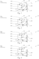
- Fig. 1 to Fig. 4 shows an example of an illumination device 10 for a vehicle headlamp, wherein the illumination device 10 provides headlamp levelling for a vehicle headlamp.
- the illumination device 10 comprises one primary light module 100 configured to emit light along a light path in a main direction X in order to project a light distribution, preferably a low beam and/or high beam light distribution, in front of the illumination device 10, in particular onto a road, wherein the primary light module 100 is rotatable around a rotation axis RA.
- the illumination device 10 comprises a moveable shield cover 200 for shielding the primary light module 100 in order to prevent the primary light module 100 to emit light in the main direction X in front of the illumination device 10.
- the illumination device 10 comprises a motion device 300 for moving simultaneously the primary light module 100 around the rotation axis RA and the shield cover 200 with respect to each other between non-illuminating positions P1a, P2a and illuminating positions P3a, P4a.
- the shield cover 200 is - seen in the main direction X - in front of the primary light module 100 blocking the light path of the primary light module 100 in order to prevent the primary light module 100 to emit light in front of the illumination device 10.
- Fig. 1 and Fig. 2 show both non-illuminating positions P1a, P2a of the primary light module 100.
- the shield cover 200 is moved away from the light path of the primary light module 100 to unblock the light path of the primary light module 100 in the main direction X in order to allow the primary light module 100 to emit light in front of the illumination device 10.
- Fig. 3 and Fig. 4 show both illuminating positions P3a, P4a of the primary light module 100, wherein the primary light module 100 is in a different defined angular position around the rotation axis RA.
- the motion device 300 comprises a linking mechanism 500 configured to link the primary light module 100 and the shield cover 200 in such a way that driving the linking mechanism 500 causes a simultaneous movement of the primary light module 100 and the shield cover 200. Further, the motion device 300 comprises a levelling motor 310 configured to drive simultaneously the movement of the primary light module 100 and the shield cover 200.
- the illumination device 10 comprises a frame 400, which is stationary in relation to the movements of the primary light module 100 and the shield cover 200, wherein the motion device 300 is mounted on the frame 400.
- each illuminating position P3a, P4a the at least one primary light module 100 is in a defined angular position of a determined operating angular range around the rotation axis RA in order to project the light distribution in different angular positions in front of the illumination device 10 to allow a headlamp levelling for a vehicle headlamp.
- the operating angular range may correspond to an angle range along the V-V line on a measuring screen from 0° to -20°.
- the shield cover 200 maintains its spatial orientation while transitioning between the non-illuminating positions P1a , P2a and the illuminating positions P3a, P4a, wherein the shield cover 200 is moveable substantially in a vertical direction - seen in a correct installed state of the illumination device 10 in a vehicle.
- the illumination device 10 comprises a housing for housing the primary light module 100, wherein the housing comprises an opaque front cover 60 having a translucent section 61, and wherein the front cover 60 is arranged downstream of the primary light module in the main direction X, wherein in the illuminating positions P3a, P4a the primary light module 100 emits light through the translucent section 61 in front of the illumination device 10.
- the shield cover 200 is also blocking the translucent section 61 of the front cover 60 in order to prevent the primary light module 100 to emit light in front of the illumination device 10, wherein in the illuminating positions P3a, P4a the shield cover 200 is moved away from the translucent section 61 of the front cover 60.
- Fig. 5 to Fig. 7 shows another example of an illumination device 20 for a vehicle headlamp, wherein the illumination device 20 provides headlamp levelling for a vehicle headlamp, and wherein the illumination device 20 comprises a primary light module 100 configured to emit light along a light path in a main direction X in order to project a light distribution, preferably a low beam and/or high beam light distribution, in front of the illumination device 20, in particular onto a road, wherein the primary light module 100 is rotatable around a rotation axis RA.
- a primary light module 100 configured to emit light along a light path in a main direction X in order to project a light distribution, preferably a low beam and/or high beam light distribution, in front of the illumination device 20, in particular onto a road, wherein the primary light module 100 is rotatable around a rotation axis RA.
- the illumination device 20 comprises a housing for housing the primary light module 100, wherein the housing comprises an opaque front cover 60 having a translucent section 61, and wherein the front cover 60 is arranged downstream of the primary light module 100 in the main direction X.
- the illumination device 20 comprises a moveable shield cover 200 for shielding the translucent section 61 of the front cover 60 in order to prevent the at least one primary light module 100 to emit light in the main direction X in front of the illumination device 10.
- the illumination device 20 comprises a secondary light module 700 configured to emit light along a light path in order to project a light distribution in front of the illumination device 20, wherein the secondary light module 700 is rotatable around the rotation axis RA.
- the secondary light module 700 is configured to emit a light distribution in front of the illumination device 20 different from the light distribution of the at least one primary light module 100, preferably the light distribution of the secondary light module 700 is a position light, a daytime running light, a sign light, or a turn indicator.
- the illumination device 20 also comprises a motion device 300 for moving simultaneously the light primary module 100 and the secondary light module 700 around the rotation axis RA and the shield cover 200 with respect to each other between non-illuminating positions P1b , intermediate positions P2b and illuminating positions P3b of the primary light module 100.
- the primary light module 100 and the secondary light module 700 are covered by the front cover 60 blocking the light path of the primary light module 100 and the secondary light module 700, wherein the shield cover 200 is blocking the translucent section 61 of the front cover 60 in order to prevent the primary light module 100 and the secondary light module 700 to emit light in front of the illumination device 20.
- Fig. 5 shows such non-illuminating position P1b of the primary light module 100 and secondary light module 700.
- the primary light module 100 is covered by the opaque front cover 60 blocking the light path of the primary light module 100, wherein the shield cover 200 is moved away from the translucent section 61 of the front cover 60 in a way to allow the secondary light module 700 to emit light in the main direction X through the translucent section 61 of the front cover 60 in front of the illumination device 20.
- Fig. 6 shows such an intermediate position P2b.
- the shield cover 200 is moved away from the translucent section 61 of the front cover 60 and the primary light module 100 is unblocked of the front cover 60 in order to allow the primary light module 100 to emit light in the main direction X through the translucent section 61 of the front cover 60 in front of the illumination device 20, and wherein the shield cover 200 or the front cover 60 blocking the light path of the secondary light module 700 in order to prevent the secondary light module 700 to emit light in front of the illumination device 20 through the translucent section 61 of the front cover 60.
- Fig. 7 shows such an illuminating position P3b of the primary light module 100, wherein the primary light module 100 is in a defined angular position around the rotation axis RA.
- the motion device 300 comprises a linking mechanism 500 configured to link the light primary module 100, the secondary light module 700 and the shield cover 200 in such a way that driving the linking mechanism 500 causes a simultaneous movement of the primary light module 100, the secondary light module 700 and the shield cover 200. Further, the motion device 300 comprises a levelling motor 310 configured to drive simultaneously the movement of the primary light module 100, the secondary module 700 and the shield cover 200.
- the illumination device 20 comprises a frame 400, which is stationary in relation to the movements of the primary light module 100, the secondary light module and the shield cover 200, wherein the motion device 300 is mounted on the frame 400.
- each illuminating position P3b the primary light module 100 is in a defined angular position of a determined operating angular range around the rotation axis RA in order to project the light distribution in different angular positions in front of the illumination device 20 to allow a headlamp levelling for a vehicle headlamp.
- the operating angular range may correspond to an angle range along the V-V line on a measuring screen from 0° to -20°.
- the shield cover 200 maintains its spatial orientation while transitioning between the non-illuminating positions P1b , the intermediate position P2b and the illuminating positions P3b, wherein the shield cover 200 is moveable substantially in a vertical direction - seen in a correct installed state of the illumination device 20 in a vehicle.
- Linking mechanism 500 Secondary light module 700 Main direction X Rotation Axis RA
- Intermediate position P2b Illuminating positions P3a, P4a, P3b
Landscapes
- Engineering & Computer Science (AREA)
- General Engineering & Computer Science (AREA)
- Mechanical Engineering (AREA)
- Non-Portable Lighting Devices Or Systems Thereof (AREA)
- Fastening Of Light Sources Or Lamp Holders (AREA)
- Lighting Device Outwards From Vehicle And Optical Signal (AREA)
Abstract
- at least one primary light module (100) configured to emit light in a main direction (X), wherein the primary light module (100) is rotatable around a rotation axis (RA),
- a moveable shield cover (200) for shielding the primary light module (100),
- a motion device (300) for moving simultaneously the primary light module (100) around the rotation axis (RA) and the shield cover (200) with respect to each other between
- non-illuminating positions (P1a, P1b, P2a) of the primary light module (100), wherein the shield cover (200) is in front of the at least one primary light module (100), and
- illuminating positions (P3a, P4a) of the light module (100), wherein the shield cover (200) is moved away from the light path of the light module (100)
wherein in each illuminating position (P3a, P3b, P4a) the at least one primary light module (100) is in a defined angular position of a determined operating angular range around the rotation axis (RA) in order to project the light distribution in different angular positions in front of the illumination device (10, 20) to allow a headlamp levelling for a vehicle headlamp.
Description
- The invention relates to an illumination device for a vehicle headlamp, wherein the illumination device provides headlamp levelling for a vehicle headlamp.
- The invention also relates to a vehicle headlamp comprising at least one illumination device according to the invention.
- There is an increased desire to provide an illumination device that allows increased safety so that no light from a light module is unintentionally emitted in front of the illumination device while providing headlamp levelling for a vehicle headlamp.
- For this purpose, there are several proposed solutions in the state of the art, which, however, are not satisfactory.
- It is an object of the invention to provide an enhanced illuminating device.
- To achieve this object, the illuminating device comprises:
- at least one primary light module configured to emit light along a light path in a main direction in order to project a light distribution, preferably a low beam and/or high beam light distribution, in front of the illumination device, in particular onto a road, wherein the at least one primary light module is rotatable around a rotation axis,
- a moveable shield cover for shielding the at least one primary light module in order to prevent the at least one primary light module to emit light in the main direction in front of the illumination device,
- a motion device for moving simultaneously the at least one primary light module around the rotation axis and the shield cover with respect to each other between
- non-illuminating positions of the at least one primary light module, wherein the shield cover is - seen in the main direction - in front of the at least one primary light module blocking the light path of the at least one primary light module in order to prevent the at least one primary light module to emit light in front of the illumination device, and
- illuminating positions of the at least one primary light module, wherein the shield cover is moved away from the light path of the at least one primary light module to unblock the light path of the at least one primary light module in the main direction in order to allow the at least one primary light module to emit light in front of the illumination device,
- a frame, which is stationary in relation to the movements of the at least one primary light module and the shield cover, wherein the motion device is mounted on the frame,
- This solution allows that even if there is a malfunction in which light of the at least one primary light module is emitted despite being switched off, it is not emitted in front of the lighting device.
- In addition, this solution also meets design requirements, whereby the at least one primary light module not in use is not visible from the outside.
- Furthermore, the solution according to the invention makes it possible to regulate the headlight levelling while shading the at least one primary light module when required.
- Advantageously, the operating angular range corresponds to an angle range along the V-V line on a measuring screen from 0° to -20°, preferably the measuring screen is conforming to ECE guidelines.
- Advantageously, the shield cover maintains its spatial orientation while transitioning between the non-illuminating positions and the illuminating positions.
- Advantageously, the shield cover is moveable substantially in a vertical direction - seen in a correct installed state of the illumination device in a vehicle.
- Advantageously, the motion device comprises a levelling motor configured to drive simultaneously the movement of the at least one primary light module and the shield cover.
- Advantageously, the motion device comprises a linking mechanism configured to link the at least one primary light module and the shield cover in such a way that driving the linking mechanism causes a simultaneous movement of the at least one primary light module and the shield cover.
- Advantageously, the illumination device comprises a front cover, preferably an opaque front cover, having a translucent section, and wherein the front cover is arranged downstream of the at least one primary light module in the main direction, wherein in the illuminating positions the at least one primary light module emits light through the translucent section in front of the illumination device. Advantageously, the illumination device comprises a housing for housing the at least one primary light module and the shield cover, wherein the housing comprises the front cover.
- Advantageously, in the non-illuminating positions, the shield cover is also blocking the translucent section of the front cover in order to prevent the at least one primary light module to emit light in front of the illumination device, wherein in the illuminating positions the shield cover is moved away from the translucent section of the front cover.
- Advantageously, the translucent section of the front cover is built as an opening, which passes through the front cover.
- To achieve this object, the illuminating device comprises:
- at least one primary light module configured to emit light along a light path in the main direction in order to project a light distribution, preferably a low beam light distribution, in front of the illumination device, in particular onto a road, wherein the at least one primary light module is rotatable around a rotation axis,
- a front cover, preferably an opaque front cover, having a translucent section, and wherein the front cover is arranged downstream of the at least one primary light module in the main direction,
- a moveable shield cover for shielding the translucent section of the front cover in order to prevent the at least one primary light module to emit light in the main direction in front of the illumination device,
- a motion device for moving simultaneously the at least one primary light module around the rotation axis and the shield cover with respect to each other between
- non-illuminating positions of the at least one primary light module, wherein the at least one primary light module is covered by the front cover blocking the light path of the at least one primary light module, and
wherein the shield cover is blocking the translucent section of the front cover in order to prevent the at least one primary light module to emit light in front of the illumination device, - illuminating positions of the at least one primary light module, wherein the shield cover is moved away from the translucent section of the front cover and the at least one primary light module is unblocked of the front cover in order to allow the at least one primary light module to emit light in the main direction through the translucent section of the front cover in front of the illumination device,
- non-illuminating positions of the at least one primary light module, wherein the at least one primary light module is covered by the front cover blocking the light path of the at least one primary light module, and
- a frame, which is stationary in relation to the movements of the at least one primary light module and the shield cover, wherein the motion device is mounted on the frame,
- Advantageously, the illumination device comprises a housing for housing the at least one primary light module, the secondary light module, and the shield cover, wherein the housing comprises the front cover.
- Advantageously, the illumination device comprises at least one secondary light module configured to emit light along a light path in order to project a light distribution in front of the illumination device, wherein the at least one secondary light module is rotatable around the rotation axis, wherein
the motion device is configured to simultaneously move the at least one primary light module and the at least one secondary light module around the rotation axis and the shield cover with respect to each other between - the non-illuminating positions, wherein the at least one primary light module and the at least one secondary light module are covered by the front cover blocking the light path of the at least one primary light module and the at least one secondary light module, and
wherein the shield cover is blocking the translucent section of the front cover in order to prevent the at least one primary light module and the at least one secondary light module to emit light in front of the illumination device, - an intermediate position, wherein the at least one primary light module is covered by the front cover blocking the light path of the at least one primary light module, wherein the shield cover is moved away from the translucent section of the front cover in a way to allow the at least one secondary light module to emit light in the main direction through the translucent section of the front cover in front of the illumination device,
- the illuminating positions of the at least one primary light module, wherein the shield cover is moved away from the translucent section of the front cover and the at least one primary light module is unblocked of the front cover in order to allow the at least one primary light module to emit light in the main direction through the translucent section of the front cover in front of the illumination device, and wherein
- Advantageously, the at least one secondary light module is configured to emit a light distribution in front of the illumination device different from the light distribution of the at least one primary light module, preferably the light distribution of the at least secondary light module is a position light, a daytime running light, a sign light, or a turn indicator.
- This solution allows that even if there is a malfunction in which light of the light module is emitted despite being switched off, it is not emitted in front of the lighting device.
- In addition, this solution also meets design requirements, whereby the at least one primary light module not in use is not visible from the outside.
- Furthermore, the solution according to the invention makes it possible to regulate the headlight levelling while shading the at least one primary light module when required.
- Advantageously, the operating angular range corresponds to an angle range along the V-V line on a measuring screen from 0° to -20°, preferably the measuring screen is conforming to ECE guidelines.
- Advantageously, the shield cover maintains its spatial orientation while transitioning between the non-illuminating positions and the illuminating positions.
- Advantageously, the shield cover is moveable substantially in a vertical direction - seen in a correct installed state of the illumination device in a vehicle.
- Advantageously, the motion device comprises a levelling motor configured to drive simultaneously the movement of the at least one primary light module and the shield cover.
- Advantageously, the motion device comprises a linking mechanism configured to link the at least one primary light module and the shield cover in such a way that driving the linking mechanism causes a simultaneous movement of the at least one primary light module and the shield cover.
- Advantageously, the motion device comprises a linking mechanism configured to link the at least one primary light module, the at least one secondary light module and the shield cover in such a way that driving the linking mechanism causes a simultaneous movement of the at least one primary light module, the at least one secondary light module and the shield cover.
- Advantageously, the translucent section of the front cover is built as an opening, which passes through the front cover.
- The object is also achieved by a vehicle headlamp comprising at least one illumination device according to the invention.
- It should be noted, that - unless otherwise stated - explanations and features which refer to one aspect of the invention also refer to the other aspect of the invention, and vice versa.
- In the following, in order to further demonstrate the present invention, illustrative and non-restrictive embodiments are discussed, as shown in the drawings, which show:
- Fig. 1
- an example of an illumination device according to the invention, comprising a primary light module, a moveable shield cover and a motion device, wherein the motion device is configured to simultaneously move the primary light module around a rotation axis and the shield cover with respect to each other, wherein in the shown figure the illumination device is in a non-illuminating position of the primary light module, in which the shield cover is in front the primary light module;
- Fig. 2
- the illumination device of
Fig. 1 in a further non-illuminating position of the primary light module, wherein the angular position of the primary light module is different to the angular position inFig. 1 ; - Fig. 3
- the illumination device of
Fig. 1 and 2 in an illuminating position of the primary light module, wherein the shield cover is moved away from the light path of the primary light module in order to allow the primary light module to emit light in front of the illumination device; - Fig. 4
- the illumination device of
Fig 1, 2 and 3 in a further illuminating position of the primary light module; - Fig. 5
- a further example of an illumination device according to the invention, wherein the illumination device is similar to the device shown in
figures 1 to 4 , wherein the illumination device comprises a secondary light module and a housing with an opaque front cover which comprises a translucent section, wherein the shown illumination device is in a non-illuminating position of the primary light module and the secondary light module; - Fig. 6
- the illumination device of
Fig. 5 in an intermediate position, where the primary light module is covered by the opaque front and the secondary light module is able to emit light through the translucent section of the front cover; - Fig. 7
- the illumination device of
Fig. 5 and 6 in an illuminating position of the primary light module, wherein the secondary light module is covered by the shield cover. -
Fig. 1 to Fig. 4 shows an example of anillumination device 10 for a vehicle headlamp, wherein theillumination device 10 provides headlamp levelling for a vehicle headlamp. Theillumination device 10 comprises oneprimary light module 100 configured to emit light along a light path in a main direction X in order to project a light distribution, preferably a low beam and/or high beam light distribution, in front of theillumination device 10, in particular onto a road, wherein theprimary light module 100 is rotatable around a rotation axis RA. - Further, the
illumination device 10 comprises amoveable shield cover 200 for shielding theprimary light module 100 in order to prevent theprimary light module 100 to emit light in the main direction X in front of theillumination device 10. - Moreover, the
illumination device 10 comprises amotion device 300 for moving simultaneously theprimary light module 100 around the rotation axis RA and theshield cover 200 with respect to each other between non-illuminating positions P1a, P2a and illuminating positions P3a, P4a. - In the non-illuminating positions P1a, P2a of the
primary light module 100, theshield cover 200 is - seen in the main direction X - in front of theprimary light module 100 blocking the light path of theprimary light module 100 in order to prevent theprimary light module 100 to emit light in front of theillumination device 10. -
Fig. 1 and Fig. 2 show both non-illuminating positions P1a, P2a of theprimary light module 100. - In the illuminating positions P3a, P4a of the
primary light module 100, theshield cover 200 is moved away from the light path of theprimary light module 100 to unblock the light path of theprimary light module 100 in the main direction X in order to allow theprimary light module 100 to emit light in front of theillumination device 10. -
Fig. 3 and Fig. 4 show both illuminating positions P3a, P4a of theprimary light module 100, wherein theprimary light module 100 is in a different defined angular position around the rotation axis RA. - The
motion device 300 comprises alinking mechanism 500 configured to link theprimary light module 100 and theshield cover 200 in such a way that driving thelinking mechanism 500 causes a simultaneous movement of theprimary light module 100 and theshield cover 200. Further, themotion device 300 comprises a levellingmotor 310 configured to drive simultaneously the movement of theprimary light module 100 and theshield cover 200. - Further, the
illumination device 10 comprises aframe 400, which is stationary in relation to the movements of theprimary light module 100 and theshield cover 200, wherein themotion device 300 is mounted on theframe 400. - In each illuminating position P3a, P4a the at least one
primary light module 100 is in a defined angular position of a determined operating angular range around the rotation axis RA in order to project the light distribution in different angular positions in front of theillumination device 10 to allow a headlamp levelling for a vehicle headlamp. The operating angular range may correspond to an angle range along the V-V line on a measuring screen from 0° to -20°. Theshield cover 200 maintains its spatial orientation while transitioning between the non-illuminating positions P1a, P2a and the illuminating positions P3a, P4a, wherein theshield cover 200 is moveable substantially in a vertical direction - seen in a correct installed state of theillumination device 10 in a vehicle. - Further, the
illumination device 10 comprises a housing for housing theprimary light module 100, wherein the housing comprises anopaque front cover 60 having atranslucent section 61, and wherein thefront cover 60 is arranged downstream of the primary light module in the main direction X, wherein in the illuminating positions P3a, P4a theprimary light module 100 emits light through thetranslucent section 61 in front of theillumination device 10. - In the non-illuminating positions P1a, P2a the
shield cover 200 is also blocking thetranslucent section 61 of thefront cover 60 in order to prevent theprimary light module 100 to emit light in front of theillumination device 10, wherein in the illuminating positions P3a, P4a theshield cover 200 is moved away from thetranslucent section 61 of thefront cover 60. -
Fig. 5 to Fig. 7 shows another example of anillumination device 20 for a vehicle headlamp, wherein theillumination device 20 provides headlamp levelling for a vehicle headlamp, and wherein theillumination device 20 comprises aprimary light module 100 configured to emit light along a light path in a main direction X in order to project a light distribution, preferably a low beam and/or high beam light distribution, in front of theillumination device 20, in particular onto a road, wherein theprimary light module 100 is rotatable around a rotation axis RA. - The
illumination device 20 comprises a housing for housing theprimary light module 100, wherein the housing comprises anopaque front cover 60 having atranslucent section 61, and wherein thefront cover 60 is arranged downstream of theprimary light module 100 in the main direction X. - Further, the
illumination device 20 comprises amoveable shield cover 200 for shielding thetranslucent section 61 of thefront cover 60 in order to prevent the at least oneprimary light module 100 to emit light in the main direction X in front of theillumination device 10. Moreover, theillumination device 20 comprises asecondary light module 700 configured to emit light along a light path in order to project a light distribution in front of theillumination device 20, wherein thesecondary light module 700 is rotatable around the rotation axis RA. Thesecondary light module 700 is configured to emit a light distribution in front of theillumination device 20 different from the light distribution of the at least oneprimary light module 100, preferably the light distribution of thesecondary light module 700 is a position light, a daytime running light, a sign light, or a turn indicator. - The
illumination device 20 also comprises amotion device 300 for moving simultaneously the lightprimary module 100 and thesecondary light module 700 around the rotation axis RA and theshield cover 200 with respect to each other between non-illuminating positions P1b, intermediate positions P2b and illuminating positions P3b of theprimary light module 100. - In the non-illuminating positions P1b, the
primary light module 100 and thesecondary light module 700 are covered by thefront cover 60 blocking the light path of theprimary light module 100 and thesecondary light module 700, wherein theshield cover 200 is blocking thetranslucent section 61 of thefront cover 60 in order to prevent theprimary light module 100 and thesecondary light module 700 to emit light in front of theillumination device 20.Fig. 5 shows such non-illuminating position P1b of theprimary light module 100 and secondarylight module 700. - In the intermediate position P2b, the
primary light module 100 is covered by theopaque front cover 60 blocking the light path of theprimary light module 100, wherein theshield cover 200 is moved away from thetranslucent section 61 of thefront cover 60 in a way to allow thesecondary light module 700 to emit light in the main direction X through thetranslucent section 61 of thefront cover 60 in front of theillumination device 20.Fig. 6 shows such an intermediate position P2b. - In the illuminating positions P3b of the
primary light module 100, theshield cover 200 is moved away from thetranslucent section 61 of thefront cover 60 and theprimary light module 100 is unblocked of thefront cover 60 in order to allow theprimary light module 100 to emit light in the main direction X through thetranslucent section 61 of thefront cover 60 in front of theillumination device 20, and wherein theshield cover 200 or thefront cover 60 blocking the light path of thesecondary light module 700 in order to prevent thesecondary light module 700 to emit light in front of theillumination device 20 through thetranslucent section 61 of thefront cover 60.Fig. 7 shows such an illuminating position P3b of theprimary light module 100, wherein theprimary light module 100 is in a defined angular position around the rotation axis RA. - The
motion device 300 comprises alinking mechanism 500 configured to link the lightprimary module 100, thesecondary light module 700 and theshield cover 200 in such a way that driving thelinking mechanism 500 causes a simultaneous movement of theprimary light module 100, thesecondary light module 700 and theshield cover 200. Further, themotion device 300 comprises a levellingmotor 310 configured to drive simultaneously the movement of theprimary light module 100, thesecondary module 700 and theshield cover 200. - Further, the
illumination device 20 comprises aframe 400, which is stationary in relation to the movements of theprimary light module 100, the secondary light module and theshield cover 200, wherein themotion device 300 is mounted on theframe 400. - In each illuminating position P3b the
primary light module 100 is in a defined angular position of a determined operating angular range around the rotation axis RA in order to project the light distribution in different angular positions in front of theillumination device 20 to allow a headlamp levelling for a vehicle headlamp. The operating angular range may correspond to an angle range along the V-V line on a measuring screen from 0° to -20°. - The
shield cover 200 maintains its spatial orientation while transitioning between the non-illuminating positions P1b, the intermediate position P2b and the illuminating positions P3b, wherein theshield cover 200 is moveable substantially in a vertical direction - seen in a correct installed state of theillumination device 20 in a vehicle.LIST OF REFERENCE SIGNS Illumination device 10, 20 Front cover 60 Translucent section 61 Primary light module 100 Movable shield cover 200 Motion device 300 Leveling motor 310 Frame 400 Linking mechanism 500 Secondary light module 700 Main direction X Rotation Axis RA Non-illuminating positions P1a, P2a, P1b Intermediate position P2b Illuminating positions P3a, P4a, P3b
Claims (14)
- Illumination device (10) for a vehicle headlamp, wherein the illumination device (10) provides headlamp levelling for a vehicle headlamp, and wherein the illumination device (10) comprises:- at least one primary light module (100) configured to emit light along a light path in a main direction (X) in order to project a light distribution, preferably a low beam light distribution, in front of the illumination device (10), in particular onto a road, wherein the at least one primary light module (100) is rotatable around a rotation axis (RA),- a moveable shield cover (200) for shielding the at least one primary light module (100) in order to prevent the at least one primary light module (100) to emit light in the main direction (X) in front of the illumination device (10),- a motion device (300) for moving simultaneously the at least one primary light module (100) around the rotation axis (RA) and the shield cover (200) with respect to each other between- non-illuminating positions (P1a, P2a) of the at least one primary light module (100), wherein the shield cover (200) is - seen in the main direction (X) - in front of the at least one primary light module (100) blocking the light path of the at least one primary light module (100) in order to prevent the at least one primary light module (100) to emit light in front of the illumination device (10), and- illuminating positions (P3a, P4a) of the at least one primary light module (100), wherein the shield cover (200) is moved away from the light path of the at least one primary light module (100) to unblock the light path of the at least one primary light module (100) in the main direction (X) in order to allow the at least one primary light module (100) to emit light in front of the illumination device (10),- a frame (400), which is stationary in relation to the movements of the at least one primary light module (100) and the shield cover (200), wherein the motion device (300) is mounted on the frame (400),wherein in each illuminating position (P3a, P4a) the at least one primary light module (100) is in a defined angular position of a determined operating angular range around the rotation axis (RA) in order to project the light distribution in different angular positions in front of the illumination device (10) to allow a headlamp levelling for a vehicle headlamp.
- Illumination device (20) for a vehicle headlamp, wherein the illumination device (20) provides headlamp levelling for a vehicle headlamp, and wherein the illumination device (20) comprises:- at least one primary light module (100) configured to emit light along a light path in a main direction (X) in order to project a light distribution, preferably a low beam light distribution, in front of the illumination device (20), in particular onto a road, wherein the at least one primary light module (100) is rotatable around a rotation axis (RA),- a front cover (60), preferably an opaque front cover (60), having a translucent section (61), and wherein the front cover (60) is arranged downstream of the at least one primary light module (100) in the main direction (X),- a moveable shield cover (200) for shielding the translucent section (61) of the front cover (60) in order to prevent the at least one primary light module (100) to emit light in the main direction (X) in front of the illumination device (20),- a motion device (300) for moving simultaneously the at least one light primary module (100) around the rotation axis (RA) and the shield cover (200) with respect to each other between- non-illuminating positions (P1b) of the at least one primary light module (100), wherein the at least one primary light module (100) is covered by the front cover (60) blocking the light path of the at least one primary light module (100), and
wherein the shield cover (200) is blocking the translucent section (61) of the front cover (60) in order to prevent the at least one primary light module (100) to emit light in front of the illumination device (20),- illuminating positions (P3b) of the at least one primary light module (100), wherein the shield cover (200) is moved away from the translucent section (61) of the front cover (60) and the at least one primary light module (100) is unblocked of the front cover (60) in order to allow the at least one primary light module (100) to emit light in the main direction (X) through the translucent section (61) of the front cover (60) in front of the illumination device (20),- a frame (400), which is stationary in relation to the movements of the at least one primary light module (100) and the shield cover (200), wherein the motion device (300) is mounted on the frame (400),wherein in each illuminating position (P3b) the at least one primary light module (100) is in a defined angular position of a determined operating angular range around the rotation axis (RA) in order to project the light distribution in different angular positions in front of the illumination device (20) to allow a headlamp levelling for a vehicle headlamp. - Illumination device (20) according to claim 2, wherein the illumination device (20) comprises at least one add-on light module (700) configured to emit light along a light path in order to project a light distribution in front of the illumination device (20), wherein the at least one add-on light module (700) is rotatable around the rotation axis (RA), wherein
the motion device is configured to simultaneously move the at least one light module (100) and the at least one add-on light module (700) around the rotation axis (RA) and the shield cover (200) with respect to each other between- the non-illuminating positions (P1b), wherein the at least one light module (100) and the at least one add-on light module (700) are covered by the front cover (60) blocking the light path of the at least one light module (100) and the at least one add-on light module (700), and
wherein the shield cover (200) is blocking the translucent section of the front cover (60) in order to prevent the at least one light module (100) and the at least one add-on light module (700) to emit light in front of the illumination device (20),- an intermediate position (P2b), wherein the at least one light module (100) is covered by the opaque front cover (60) blocking the light path of the at least one light module (100), wherein the shield cover (200) is moved away from the translucent section (61) of the front cover (60) in a way to allow the at least one add-on light module (700) to emit light in the main direction (X) through the translucent section (61) of the front cover (60) in front of the illumination device (20),- the illuminating positions (P3b) of the at least one light module (100), wherein the shield cover (200) is moved away from the translucent section (61) of the front cover (60) and the at least one light module (100) is unblocked of the front cover (60) in order to allow the at least one light module (100) to emit light in the main direction (X) through the translucent section (61) of the front cover (60) in front of the illumination device (20), and whereinthe shield cover (200) or the front cover (60) blocking the light path of the at least one add-on light module (700) in order to prevent the at least one add-on light module (700) to emit light in front of the illumination device (20) through the translucent section (61) of the front cover (60). - Illumination device (20) according to claim 3, wherein the at least one secondary module (700) is configured to emit a light distribution in front of the illumination device (20) different from the light distribution of the at least one primary light module (100), preferably the light distribution of the at least secondary light module (700) is a position light, a daytime running light, a sign light, or a turn indicator.
- Illumination device (10, 20) according to any one of the claims 1 to 4, wherein the operating angular range corresponds to an angle range along the V-V line on a measuring screen from 0° to -20°.
- Illumination device (10, 20) according to any one of the claims 1 to 5, wherein the shield cover (200) maintains its spatial orientation while transitioning between the non-illuminating positions (P1a, P2a) and the illuminating positions (P3a, P4a).
- Illumination device (10, 20) according to any one of the claims 1 to 6, wherein the shield cover (200) is moveable substantially in a vertical direction - seen in a correct installed state of the illumination device (10, 20) in a vehicle.
- Illumination device (10, 20) according to any one of claims 1 to 7, wherein the motion device (300) comprises a levelling motor (310) configured to drive simultaneously the movement of the at least one primary light module (100) and the shield cover (200).
- Illumination device (20) according to any one of claims 3 to 7, wherein the motion device (300) comprises a levelling motor (310) configured to drive simultaneously the movement of the at least one primary light module (100), the secondary light module (700) and the shield cover (200).
- Illumination device (10, 20) according to any one of claims 1 to 9, wherein the motion device (300) comprises a linking mechanism (500) configured to link the primary light module (100) and the shield cover (200) in such a way that driving the linking mechanism (500) causes a simultaneous movement of the primary light module (100) and the shield cover (200).
- Illumination device (20) according to any one of claims 3 to 10, wherein the motion device (300) comprises a linking mechanism (500) configured to link the at least one primary light module (100), the at least one secondary light module (700) and the shield cover (200) in such a way that driving the linking mechanism (500) causes a simultaneous movement of the at least one primary light module (100), the at least one secondary light module (700) and the shield cover (200).
- Illumination device (10, 20) according to any one of claims 1, 5 to 11, wherein the illumination device (10, 20) comprises a front cover (60), preferably an opaque front cover (60), having a translucent section (61), and wherein the front cover (60) is arranged downstream of the at least one primary light module (100) in the main direction (X), wherein in the illuminating positions (P3a, P4a) the at least one light module (100) emits light through the translucent section (61) in front of the illumination device (10).
- Illumination device (10, 20) according to claim 12, wherein in the non-illuminating positions (P1a, P1b, P2a) the shield cover (200) is also blocking the translucent section (61) of the front cover (60) in order to prevent the at least one primary light module (100) to emit light in front of the illumination device (10, 20), wherein in the illuminating positions (P3a, P4a, P3b) the shield cover (200) is moved away from the translucent section (61) of the front cover (60).
- Vehicle headlamp comprising at least one illumination device (10, 20) according to any one of the claims 1 to 13.
Priority Applications (6)
| Application Number | Priority Date | Filing Date | Title |
|---|---|---|---|
| EP25194358.5A EP4620736A3 (en) | 2022-09-28 | 2022-09-28 | Illumination device for a vehicle headlamp |
| EP22198420.6A EP4345369B1 (en) | 2022-09-28 | 2022-09-28 | Illumination device for a vehicle headlamp |
| JP2023130755A JP7660626B2 (en) | 2022-09-28 | 2023-08-10 | Automotive floodlight lighting equipment |
| US18/244,032 US12117140B2 (en) | 2022-09-28 | 2023-09-08 | Illumination device for vehicle headlamp having a light module and shield cover that simultaneously move with respect to eachother |
| KR1020230125330A KR102986021B1 (en) | 2022-09-28 | 2023-09-20 | Illumination device for a vehicle headlamp |
| CN202311256514.9A CN117781215A (en) | 2022-09-28 | 2023-09-26 | Lighting device for a vehicle headlight |
Applications Claiming Priority (1)
| Application Number | Priority Date | Filing Date | Title |
|---|---|---|---|
| EP22198420.6A EP4345369B1 (en) | 2022-09-28 | 2022-09-28 | Illumination device for a vehicle headlamp |
Related Child Applications (2)
| Application Number | Title | Priority Date | Filing Date |
|---|---|---|---|
| EP25194358.5A Division EP4620736A3 (en) | 2022-09-28 | 2022-09-28 | Illumination device for a vehicle headlamp |
| EP25194358.5A Division-Into EP4620736A3 (en) | 2022-09-28 | 2022-09-28 | Illumination device for a vehicle headlamp |
Publications (2)
| Publication Number | Publication Date |
|---|---|
| EP4345369A1 true EP4345369A1 (en) | 2024-04-03 |
| EP4345369B1 EP4345369B1 (en) | 2026-01-21 |
Family
ID=83506595
Family Applications (2)
| Application Number | Title | Priority Date | Filing Date |
|---|---|---|---|
| EP25194358.5A Pending EP4620736A3 (en) | 2022-09-28 | 2022-09-28 | Illumination device for a vehicle headlamp |
| EP22198420.6A Active EP4345369B1 (en) | 2022-09-28 | 2022-09-28 | Illumination device for a vehicle headlamp |
Family Applications Before (1)
| Application Number | Title | Priority Date | Filing Date |
|---|---|---|---|
| EP25194358.5A Pending EP4620736A3 (en) | 2022-09-28 | 2022-09-28 | Illumination device for a vehicle headlamp |
Country Status (5)
| Country | Link |
|---|---|
| US (1) | US12117140B2 (en) |
| EP (2) | EP4620736A3 (en) |
| JP (1) | JP7660626B2 (en) |
| KR (1) | KR102986021B1 (en) |
| CN (1) | CN117781215A (en) |
Citations (7)
| Publication number | Priority date | Publication date | Assignee | Title |
|---|---|---|---|---|
| FR2754500A1 (en) * | 1996-10-15 | 1998-04-17 | Bosch Gmbh Robert | PROJECTOR INSTALLATION FOR VEHICLE EMITTING A VARIABLE LIGHT BEAM |
| US5769525A (en) * | 1994-10-04 | 1998-06-23 | Robert Bosch Gmbh | Low/high beam headlight for vehicles |
| EP1985913A1 (en) * | 2007-04-25 | 2008-10-29 | Valeo Vision | Automobile headlight comprising an optical module equipped with a mobile shade |
| US20110006685A1 (en) * | 2007-08-01 | 2011-01-13 | Gm Global Technology Operations, Inc. | Lighting device for a motor vehicle and method for controlling a lamp |
| EP2423047A2 (en) * | 2010-08-31 | 2012-02-29 | Valeo Vision | Lighting and/or signalling device with a mobile daytime element |
| US20140063834A1 (en) * | 2012-08-31 | 2014-03-06 | Sl Corporation | Head lamp for vehicle and method of controlling the same |
| US20170089538A1 (en) * | 2015-09-25 | 2017-03-30 | GM Global Technology Operations LLC | Headlamp assembly with rotating bezel |
Family Cites Families (6)
| Publication number | Priority date | Publication date | Assignee | Title |
|---|---|---|---|---|
| JPH02230603A (en) * | 1989-03-03 | 1990-09-13 | Stanley Electric Co Ltd | Headlamp for vehicle |
| JPH11176208A (en) * | 1997-12-11 | 1999-07-02 | Stanley Electric Co Ltd | Vehicle headlights |
| JP4102240B2 (en) * | 2003-04-08 | 2008-06-18 | 株式会社小糸製作所 | Vehicle headlamp |
| JP2015153512A (en) * | 2014-02-12 | 2015-08-24 | 株式会社小糸製作所 | Vehicle lamp |
| US10457193B2 (en) | 2014-03-03 | 2019-10-29 | Koito Manufacturing Co., Ltd. | Vehicle lamp and vehicle lamp control system |
| US11346519B2 (en) | 2018-12-03 | 2022-05-31 | Volvo Car Corporation | Vehicle light assembly including a movable light signature member |
-
2022
- 2022-09-28 EP EP25194358.5A patent/EP4620736A3/en active Pending
- 2022-09-28 EP EP22198420.6A patent/EP4345369B1/en active Active
-
2023
- 2023-08-10 JP JP2023130755A patent/JP7660626B2/en active Active
- 2023-09-08 US US18/244,032 patent/US12117140B2/en active Active
- 2023-09-20 KR KR1020230125330A patent/KR102986021B1/en active Active
- 2023-09-26 CN CN202311256514.9A patent/CN117781215A/en active Pending
Patent Citations (7)
| Publication number | Priority date | Publication date | Assignee | Title |
|---|---|---|---|---|
| US5769525A (en) * | 1994-10-04 | 1998-06-23 | Robert Bosch Gmbh | Low/high beam headlight for vehicles |
| FR2754500A1 (en) * | 1996-10-15 | 1998-04-17 | Bosch Gmbh Robert | PROJECTOR INSTALLATION FOR VEHICLE EMITTING A VARIABLE LIGHT BEAM |
| EP1985913A1 (en) * | 2007-04-25 | 2008-10-29 | Valeo Vision | Automobile headlight comprising an optical module equipped with a mobile shade |
| US20110006685A1 (en) * | 2007-08-01 | 2011-01-13 | Gm Global Technology Operations, Inc. | Lighting device for a motor vehicle and method for controlling a lamp |
| EP2423047A2 (en) * | 2010-08-31 | 2012-02-29 | Valeo Vision | Lighting and/or signalling device with a mobile daytime element |
| US20140063834A1 (en) * | 2012-08-31 | 2014-03-06 | Sl Corporation | Head lamp for vehicle and method of controlling the same |
| US20170089538A1 (en) * | 2015-09-25 | 2017-03-30 | GM Global Technology Operations LLC | Headlamp assembly with rotating bezel |
Also Published As
| Publication number | Publication date |
|---|---|
| CN117781215A (en) | 2024-03-29 |
| KR102986021B1 (en) | 2026-07-02 |
| EP4620736A2 (en) | 2025-09-24 |
| EP4620736A3 (en) | 2025-11-05 |
| US20240102630A1 (en) | 2024-03-28 |
| KR20240044341A (en) | 2024-04-04 |
| EP4345369B1 (en) | 2026-01-21 |
| JP2024049336A (en) | 2024-04-09 |
| US12117140B2 (en) | 2024-10-15 |
| JP7660626B2 (en) | 2025-04-11 |
Similar Documents
| Publication | Publication Date | Title |
|---|---|---|
| US12358423B2 (en) | Optical device and direction display device | |
| CN113382888B (en) | Lighting systems for motor vehicles | |
| JPWO2018135356A1 (en) | VEHICLE LIGHT SYSTEM, VEHICLE LIGHT CONTROL DEVICE, AND VEHICLE LIGHT CONTROL METHOD | |
| US7712934B2 (en) | Vehicle headlamp with daytime running light | |
| JP2017030735A (en) | System and method for controlling light beam and corresponding lighting and/or signaling module | |
| EP2154426A2 (en) | Vehicle headlamp apparatus | |
| US9657911B2 (en) | Spotlight for a motor vehicle | |
| EP4620736A2 (en) | Illumination device for a vehicle headlamp | |
| WO2024009936A1 (en) | Vehicle lamp and vehicle lamp control method | |
| US20050152151A1 (en) | Adverse weather automatic sign light shield | |
| US20240308413A1 (en) | Illumination Device for a Motor Vehicle Headlamp | |
| WO2017195353A1 (en) | Vehicle-mounted headlight and vehicle-mounted headlight system | |
| JP2013134955A (en) | Vehicular headlight device | |
| JP2021160668A (en) | Vehicle interior imager | |
| CN116989288A (en) | Roller shading structure, car light module, car lights and vehicles | |
| WO2025234100A1 (en) | Headlight control device | |
| JP2024140900A (en) | Vehicle headlights | |
| KR0112379Y1 (en) | Lens shifter of car headlight | |
| WO2025022940A1 (en) | Lamp system, light distribution control device, and computer program | |
| WO2024075466A1 (en) | Vehicle lamp | |
| KR20150059353A (en) | Automotive headlamp | |
| EP3581433A1 (en) | Vehicle front headlight device | |
| CZ301707B6 (en) | Adaptive system of motor vehicle headlights | |
| JP2004012230A (en) | Automotive instrument structure | |
| JPH0340302A (en) | Projector type illuminating device |
Legal Events
| Date | Code | Title | Description |
|---|---|---|---|
| PUAI | Public reference made under article 153(3) epc to a published international application that has entered the european phase |
Free format text: ORIGINAL CODE: 0009012 |
|
| STAA | Information on the status of an ep patent application or granted ep patent |
Free format text: STATUS: THE APPLICATION HAS BEEN PUBLISHED |
|
| AK | Designated contracting states |
Kind code of ref document: A1 Designated state(s): AL AT BE BG CH CY CZ DE DK EE ES FI FR GB GR HR HU IE IS IT LI LT LU LV MC MK MT NL NO PL PT RO RS SE SI SK SM TR |
|
| STAA | Information on the status of an ep patent application or granted ep patent |
Free format text: STATUS: REQUEST FOR EXAMINATION WAS MADE |
|
| 17P | Request for examination filed |
Effective date: 20241001 |
|
| RBV | Designated contracting states (corrected) |
Designated state(s): AL AT BE BG CH CY CZ DE DK EE ES FI FR GB GR HR HU IE IS IT LI LT LU LV MC MK MT NL NO PL PT RO RS SE SI SK SM TR |
|
| STAA | Information on the status of an ep patent application or granted ep patent |
Free format text: STATUS: EXAMINATION IS IN PROGRESS |
|
| 17Q | First examination report despatched |
Effective date: 20241218 |
|
| RIC1 | Information provided on ipc code assigned before grant |
Ipc: F21S 41/19 20180101AFI20250912BHEP Ipc: F21S 41/47 20180101ALI20250912BHEP Ipc: F21S 41/657 20180101ALI20250912BHEP Ipc: F21S 41/686 20180101ALI20250912BHEP Ipc: F21S 43/19 20180101ALI20250912BHEP Ipc: F21S 43/50 20180101ALI20250912BHEP Ipc: B60Q 1/05 20060101ALI20250912BHEP Ipc: B60Q 1/11 20060101ALI20250912BHEP Ipc: B60Q 1/26 20060101ALN20250912BHEP |
|
| GRAP | Despatch of communication of intention to grant a patent |
Free format text: ORIGINAL CODE: EPIDOSNIGR1 |
|
| STAA | Information on the status of an ep patent application or granted ep patent |
Free format text: STATUS: GRANT OF PATENT IS INTENDED |
|
| RIC1 | Information provided on ipc code assigned before grant |
Ipc: F21S 41/19 20180101AFI20250923BHEP Ipc: F21S 41/47 20180101ALI20250923BHEP Ipc: F21S 41/657 20180101ALI20250923BHEP Ipc: F21S 41/686 20180101ALI20250923BHEP Ipc: F21S 43/19 20180101ALI20250923BHEP Ipc: F21S 43/50 20180101ALI20250923BHEP Ipc: B60Q 1/05 20060101ALI20250923BHEP Ipc: B60Q 1/11 20060101ALI20250923BHEP Ipc: B60Q 1/26 20060101ALN20250923BHEP |
|
| INTG | Intention to grant announced |
Effective date: 20251027 |
|
| GRAS | Grant fee paid |
Free format text: ORIGINAL CODE: EPIDOSNIGR3 |
|
| GRAA | (expected) grant |
Free format text: ORIGINAL CODE: 0009210 |
|
| STAA | Information on the status of an ep patent application or granted ep patent |
Free format text: STATUS: THE PATENT HAS BEEN GRANTED |
|
| AK | Designated contracting states |
Kind code of ref document: B1 Designated state(s): AL AT BE BG CH CY CZ DE DK EE ES FI FR GB GR HR HU IE IS IT LI LT LU LV MC MK MT NL NO PL PT RO RS SE SI SK SM TR |
|
| REG | Reference to a national code |
Ref country code: CH Ref legal event code: F10 Free format text: ST27 STATUS EVENT CODE: U-0-0-F10-F00 (AS PROVIDED BY THE NATIONAL OFFICE) Effective date: 20260121 |
|
| REG | Reference to a national code |
Ref country code: DE Ref legal event code: R096 Ref document number: 602022028765 Country of ref document: DE |
|
| REG | Reference to a national code |
Ref country code: IE Ref legal event code: FG4D |
|
| P01 | Opt-out of the competence of the unified patent court (upc) registered |
Free format text: CASE NUMBER: UPC_APP_0009679_4345369/2026 Effective date: 20260312 |
|
| REG | Reference to a national code |
Ref country code: NL Ref legal event code: MP Effective date: 20260121 |
|
| PG25 | Lapsed in a contracting state [announced via postgrant information from national office to epo] |
Ref country code: NL Free format text: LAPSE BECAUSE OF FAILURE TO SUBMIT A TRANSLATION OF THE DESCRIPTION OR TO PAY THE FEE WITHIN THE PRESCRIBED TIME-LIMIT Effective date: 20260121 |
|
| REG | Reference to a national code |
Ref country code: AT Ref legal event code: MK05 Ref document number: 1878992 Country of ref document: AT Kind code of ref document: T Effective date: 20260121 |
|
| PG25 | Lapsed in a contracting state [announced via postgrant information from national office to epo] |
Ref country code: RS Free format text: LAPSE BECAUSE OF FAILURE TO SUBMIT A TRANSLATION OF THE DESCRIPTION OR TO PAY THE FEE WITHIN THE PRESCRIBED TIME-LIMIT Effective date: 20260421 |
|
| PG25 | Lapsed in a contracting state [announced via postgrant information from national office to epo] |
Ref country code: ES Free format text: LAPSE BECAUSE OF FAILURE TO SUBMIT A TRANSLATION OF THE DESCRIPTION OR TO PAY THE FEE WITHIN THE PRESCRIBED TIME-LIMIT Effective date: 20260121 |
|
| PG25 | Lapsed in a contracting state [announced via postgrant information from national office to epo] |
Ref country code: PL Free format text: LAPSE BECAUSE OF FAILURE TO SUBMIT A TRANSLATION OF THE DESCRIPTION OR TO PAY THE FEE WITHIN THE PRESCRIBED TIME-LIMIT Effective date: 20260121 |
|
| PG25 | Lapsed in a contracting state [announced via postgrant information from national office to epo] |
Ref country code: GR Free format text: LAPSE BECAUSE OF FAILURE TO SUBMIT A TRANSLATION OF THE DESCRIPTION OR TO PAY THE FEE WITHIN THE PRESCRIBED TIME-LIMIT Effective date: 20260422 |
|
| REG | Reference to a national code |
Ref country code: LT Ref legal event code: MG9D |
|
| PG25 | Lapsed in a contracting state [announced via postgrant information from national office to epo] |
Ref country code: LT Free format text: LAPSE BECAUSE OF FAILURE TO SUBMIT A TRANSLATION OF THE DESCRIPTION OR TO PAY THE FEE WITHIN THE PRESCRIBED TIME-LIMIT Effective date: 20260121 |
|
| PG25 | Lapsed in a contracting state [announced via postgrant information from national office to epo] |
Ref country code: NO Free format text: LAPSE BECAUSE OF FAILURE TO SUBMIT A TRANSLATION OF THE DESCRIPTION OR TO PAY THE FEE WITHIN THE PRESCRIBED TIME-LIMIT Effective date: 20260421 |
|
| PG25 | Lapsed in a contracting state [announced via postgrant information from national office to epo] |
Ref country code: SE Free format text: LAPSE BECAUSE OF FAILURE TO SUBMIT A TRANSLATION OF THE DESCRIPTION OR TO PAY THE FEE WITHIN THE PRESCRIBED TIME-LIMIT Effective date: 20260121 Ref country code: AT Free format text: LAPSE BECAUSE OF FAILURE TO SUBMIT A TRANSLATION OF THE DESCRIPTION OR TO PAY THE FEE WITHIN THE PRESCRIBED TIME-LIMIT Effective date: 20260121 Ref country code: FI Free format text: LAPSE BECAUSE OF FAILURE TO SUBMIT A TRANSLATION OF THE DESCRIPTION OR TO PAY THE FEE WITHIN THE PRESCRIBED TIME-LIMIT Effective date: 20260121 |
|
| PG25 | Lapsed in a contracting state [announced via postgrant information from national office to epo] |
Ref country code: HR Free format text: LAPSE BECAUSE OF FAILURE TO SUBMIT A TRANSLATION OF THE DESCRIPTION OR TO PAY THE FEE WITHIN THE PRESCRIBED TIME-LIMIT Effective date: 20260121 |
|
| PG25 | Lapsed in a contracting state [announced via postgrant information from national office to epo] |
Ref country code: IS Free format text: LAPSE BECAUSE OF FAILURE TO SUBMIT A TRANSLATION OF THE DESCRIPTION OR TO PAY THE FEE WITHIN THE PRESCRIBED TIME-LIMIT Effective date: 20260521 Ref country code: PT Free format text: LAPSE BECAUSE OF FAILURE TO SUBMIT A TRANSLATION OF THE DESCRIPTION OR TO PAY THE FEE WITHIN THE PRESCRIBED TIME-LIMIT Effective date: 20260521 |
|
| PG25 | Lapsed in a contracting state [announced via postgrant information from national office to epo] |
Ref country code: LV Free format text: LAPSE BECAUSE OF FAILURE TO SUBMIT A TRANSLATION OF THE DESCRIPTION OR TO PAY THE FEE WITHIN THE PRESCRIBED TIME-LIMIT Effective date: 20260121 |
|
| PG25 | Lapsed in a contracting state [announced via postgrant information from national office to epo] |
Ref country code: BG Free format text: LAPSE BECAUSE OF FAILURE TO SUBMIT A TRANSLATION OF THE DESCRIPTION OR TO PAY THE FEE WITHIN THE PRESCRIBED TIME-LIMIT Effective date: 20260121 |