EP4345327A1 - Achsausgleichsmodul - Google Patents
Achsausgleichsmodul Download PDFInfo
- Publication number
- EP4345327A1 EP4345327A1 EP23000132.3A EP23000132A EP4345327A1 EP 4345327 A1 EP4345327 A1 EP 4345327A1 EP 23000132 A EP23000132 A EP 23000132A EP 4345327 A1 EP4345327 A1 EP 4345327A1
- Authority
- EP
- European Patent Office
- Prior art keywords
- compensation module
- axle compensation
- axle
- group
- linear
- Prior art date
- Legal status (The legal status is an assumption and is not a legal conclusion. Google has not performed a legal analysis and makes no representation as to the accuracy of the status listed.)
- Granted
Links
Images



Classifications
-
- B—PERFORMING OPERATIONS; TRANSPORTING
- B25—HAND TOOLS; PORTABLE POWER-DRIVEN TOOLS; MANIPULATORS
- B25J—MANIPULATORS; CHAMBERS PROVIDED WITH MANIPULATION DEVICES
- B25J17/00—Joints
- B25J17/02—Wrist joints
- B25J17/0208—Compliance devices
- B25J17/0225—Compliance devices with axial compliance, i.e. parallel to the longitudinal wrist axis
-
- B—PERFORMING OPERATIONS; TRANSPORTING
- B25—HAND TOOLS; PORTABLE POWER-DRIVEN TOOLS; MANIPULATORS
- B25J—MANIPULATORS; CHAMBERS PROVIDED WITH MANIPULATION DEVICES
- B25J19/00—Accessories fitted to manipulators, e.g. for monitoring, for viewing; Safety devices combined with or specially adapted for use in connection with manipulators
- B25J19/06—Safety devices
- B25J19/063—Safety devices working only upon contact with an outside object
-
- F—MECHANICAL ENGINEERING; LIGHTING; HEATING; WEAPONS; BLASTING
- F16—ENGINEERING ELEMENTS AND UNITS; GENERAL MEASURES FOR PRODUCING AND MAINTAINING EFFECTIVE FUNCTIONING OF MACHINES OR INSTALLATIONS; THERMAL INSULATION IN GENERAL
- F16C—SHAFTS; FLEXIBLE SHAFTS; ELEMENTS OR CRANKSHAFT MECHANISMS; ROTARY BODIES OTHER THAN GEARING ELEMENTS; BEARINGS
- F16C29/00—Bearings for parts moving only linearly
- F16C29/008—Systems with a plurality of bearings, e.g. four carriages supporting a slide on two parallel rails
Definitions
- the invention relates to an axle compensation module as an intermediate flange assembly of a linear axis with a housing which has a cover group and a base group loaded relative to this by means of a spring element.
- the DE 10 2013 220 148 B3 discloses a one-piece axle compensation element produced using a generative process. There is a risk of damage under high operating loads.
- the present invention is based on the problem of developing an axle compensation element for high torque loads.
- the cover group and the base group are guided relative to one another in a longitudinal direction by means of a linear guide system.
- the linear guide system has at least three bearing groups, each with two linear rolling bearing units.
- axle compensation module When unloaded and without the influence of external forces, the axle compensation module is in an extended position.
- the spring element pushes the cover group and the base group apart.
- the housing limits the stroke in the direction of the extended position.
- the cover group and the base group are moved longitudinally relative to each other.
- the height of the axle compensation module is shortened in the longitudinal direction.
- the spring element is loaded and, if necessary, a pressure-loaded pressure chamber is compressed.
- the resistance of the axle compensation module against a further retraction stroke movement increases, for example, with increasing retraction stroke.
- This linear guide system has at least three bearing groups, with each bearing group having at least two linear rolling bearing units.
- the linear rolling bearing units each have several cage-guided ones Needles or rollers as rolling elements.
- the rolling elements roll on both the base assembly and the cover assembly.
- the cage is a flat cage that stores the individual rolling elements at a distance from each other.
- This bearing has a high effective static and dynamic load capacity. This limits the deformation when there are high bending or torsional moments acting on the axle compensation module.
- the axle compensation module is therefore highly resilient.
- the Figures 1 - 5 show an axle compensation module (10) and some of its individual parts.
- axle compensation modules (10) are used, for example, in linear axes of handling devices to handle components with large dimensional tolerances or in inaccurate positions.
- the axis compensation module (10) forms an intermediate flange assembly (10) which is arranged between the last joint of the handling device and, for example, a gripping device.
- the axle compensation module (10) has a housing (11). This has a first fastening flange (22) arranged on a cover group (21) and a second fastening flange (72) arranged on a base group (71).
- the two fastening flanges (22, 72) are designed to be congruent with one another, for example, so that, for example, the gripping device can be attached to the handling device without the axle compensation module (10).
- the two fastening flanges (22, 72) are designed in accordance with ISO 9409-1. According to this standard, the nominal size of the respective fastening flange (22; 72) is designated according to the diameter of the pitch circle (23; 73) for its fastening screws (24).
- the axle compensation module (10) shown in the figures has the nominal size 100. Its pitch circles of the fastening flanges (22, 72) have a diameter of 100 millimeters.
- geometrically similar axle compensation modules (10) can be staggered according to a geometric series, e.g. the decimal geometric normal number series R 10 according to DIN 323.
- the base group (71) has threaded holes (74) of the same diameter on the pitch circle (73), which are closed, for example, by means of locking inserts (75), as well as a cylinder bolt holder (not shown here).
- the fastening screws (24) protrude from the front side (12) of the axle compensation module (10). Furthermore, there are, for example, three centering pins (26) on the pitch circle (23), which center a guide support ring (41) on a cover part (31). On the front side (12) of the cover group (21) there is also a centering ring (27), for example for centering the axle compensation module (10) on the handling device.
- a centering seat (77) is formed in the base assembly (71). This is, for example, a depression whose diameter is 63% of the diameter of the pitch circle (73).
- the depth of the centering seat (77) is, for example, 6% of the nominal size of the axle compensation module (10).
- six piston fastening screws (78) are arranged on a common pitch circle.
- the axle compensation module (10) shown in the figures has a cylindrical envelope contour.
- the center line (14) is oriented in the longitudinal direction (15) of the axle compensation module (10).
- the diameter of the cover group (21) is, for example, 1.4 times the nominal size.
- the base group (71) is accommodated in the cover group (21), the diameter of which is, for example, 96% of the diameter of the cover group (21).
- the height of the extended axle compensation element (10) corresponds, for example, to the nominal size of the axle compensation module (10). It is also conceivable to design the axle compensation module (10) with a cuboid envelope contour.
- a media connection (13) is arranged on the outer surface (28) of the cover group (21). In the exemplary embodiment, this is a pneumatic connection (13).
- the axle compensation module (10) can also be designed without a media connection (13).
- a vent connection (16) is provided on the casing surface (28). This can have a sieve to prevent the ingress of contaminants.
- the cover group (21) shown has a sensor holder (17). This is arranged on the outer surface (28) of the cover group (21).
- a path-dependent sensor can be inserted into the sensor holder (17). This can be a magnetic sensor, an inductive or capacitive sensor, etc.
- the stroke of the axle compensation module (10) in the longitudinal direction (15) is 15% of the nominal size in the exemplary embodiment.
- the stroke of the axle compensation module (10) is the change in the total length oriented in the longitudinal direction (10) by which the base group (71) can be displaced relative to the cover group (21). This stroke is greater than or equal to 10% of the nominal size of the axle compensation module (10).
- the height of the floor assembly (71) oriented in the longitudinal direction (15) is 70% of the nominal size of the axle compensation element (10).
- the base group (71) is cup-shaped. It has a base part (81), the piston (101) and, for example, six guide blocks (111) with stop plates (112).
- the base part (81), cf. the Figures 2 and 3 has a bottom (82) and a wall (91) protruding from the floor.
- the thickness of the base (82) and the wall (91) is each, for example, up to 15% of the nominal size of the axle compensation module (10).
- the base (82) has an annular, flat support surface (83) with a central centering recess (84).
- the openings (85) for the piston fastening screws (78) are arranged in this support surface (83).
- the wall (91) has on its outside (92) e.g. 12 through holes (93) and centering pin holders (94).
- each of the through holes (93) is assigned a centering pin receptacle (94).
- Two through holes (93) are arranged offset from one another in the longitudinal direction (15).
- the individual groups of through holes (93) and centering pin receptacles (94) are evenly distributed in the wall (91) in the circumferential direction (18).
- the wall (91) has a ring receptacle (95) on its outside (92).
- a sealing ring (96) in this ring receptacle (95).
- the inner wall of the base part (81) has flats (97) in the area of the through holes (93).
- a guide block (111) rests against each of these.
- all guide blocks (111) are identical and have a cuboid shape. For example, their height in the longitudinal direction (15) is 55% of the nominal size. Their width in a tangential direction to the circumferential direction (18) is e.g. 12% of the nominal size. Their depth parallel to a radial plane in which the center line (14) lies is 11% of the nominal size in the exemplary embodiment.
- the two surfaces of the guide block (111) that are parallel to the aforementioned radial plane are referred to below as rolling surfaces (113). These rolling surfaces (113) are, for example, hardened and have, for example, a hardness between 58 HRC and 64 HRC.
- the guide blocks (111) in a prism shape.
- the rolling surfaces (113) then enclose an angle of up to 120 degrees with one another in a plane normal to the longitudinal direction (15). In this case, the apex of this angle is oriented in the direction of the center line (14) of the axle compensation module (10).
- the stop plate (112) is screwed onto the upper end face of the individual guide block (113).
- the individual stop plate (112) projects beyond both rolling surfaces (113).
- the top of the stop plates (112) is, for example, flush with the upper edge of the wall (91).
- a piston (101) rests on the support surface (83).
- the piston (101) is secured there using the piston fastening screws (78).
- Its underside has a centering tip (102) which, when the axle compensation module (10) is installed, projects into the centering recess (84) of the base (82).
- the top of the piston (106) has a circumferential ring (107) which delimits a pressure and support surface (108).
- the illustration shows the support on this pressure and support surface (108).
- Figure 2 a spring element (121).
- the spring element (121) is a compression spring (121) that presses the cover group (21) and the base group (71) apart.
- the spring element (121) is located in a pressure chamber (122) that is enclosed by the cover group (21) and the base group (71).
- a stroke stop (42) of the cover group (21) forms an extension stop (42) of the axle compensation module (10).
- the piston (101) rests with its shoulder (104) on the extension stop (42).
- the pressure chamber (122) can be subjected to media pressure through the media connection (13).
- the media pressure adds up to the load on the cover group (21) and the base group (71) generated by the spring element (121), so that the rigidity of the axle compensation module (10) increases with an additional media pressure load.
- the additional pressure in the pressure chamber (122) is reduced.
- the axle compensation module (10) is then only loaded by means of the spring element (121).
- air is displaced from the space outside the pressure chamber delimited by the sealing ring (96), for example through the vent connection (16).
- the cover group (21), cf. the Figures 2 and 4 has the cover part (31) with a cover (32) and the guide support ring (41) attached to it.
- the top of the cover (32) forms the front side (12) of the cover group (21) described above.
- the inside of the cover (32) has a spring holder (33). This delimits the pressure chamber (122) in the longitudinal direction (15). It is designed, for example, as a circular flat surface.
- the cover (32) has a guide support ring centering (34) on its inside.
- the guide support ring centering (34) carries a sealing ring (35) which rests, for example, on the guide support ring (41).
- the guide support ring (41) has a cylindrical inner wall (43). This is limited in the lower area by the extension stop (42).
- the outer wall (44) of the guide support ring (41) has a cylindrical envelope contour. This is defined by, for example, six studs (51) evenly distributed around the circumference.
- Each stud (51) is delimited in the circumferential direction (18) by two support surfaces (52).
- the individual support surface (52) has a height oriented in the longitudinal direction (15) of, for example, 55% of the nominal size and a width, oriented normally to this, of, for example, 10% of the nominal size.
- the individual support surface (52) is designed as a flat surface (52).
- Two adjacent studs (51) delimit a guide recess (53) with their support surfaces (52).
- a guide block (111), two linear roller bearing units (132) and two rolling plates (135) are located in a guide recess (53).
- the two linear rolling bearing units (132) form a bearing group (136) of a linear guide system (131).
- the linear guide system (131) of the axle compensation module (10) has at least three bearing groups (136) of similar design.
- the axle compensation module (10) of the exemplary embodiment shown in the figures has six bearing groups (136), each with two linear rolling bearing units (132).
- the support surfaces (52) are aligned parallel to the rolling surfaces (113) of the guide blocks (111).
- the mutually oriented support surfaces (52) of two adjacent studs (51) are parallel to one another. If the rolling surfaces (113) are not parallel, the angle enclosed by the support surfaces (52) in a plane normal to the longitudinal direction (15) is adjusted accordingly.
- the rolling plates (135) are metal strips with a thickness of up to 2% of the nominal size. They are, for example, hardened and ground. Each rolling plate (135) completely covers a support surface (52). A stop hook (54) and a Support hooks prevent the rolling plates (135) from shifting.
- a linear roller bearing unit (132) of the linear guide system (131) is located between each rolling plate (135) and each rolling surface (113). It is also conceivable to additionally arrange a rolling plate (135) on the individual rolling surface (113).
- the individual linear roller bearing unit (132) has a roller bearing cage (133) in the form of a flat cage and rolling elements (134) rotatably mounted therein, e.g. in the form of needles (134).
- the length of the roller bearing cage (133) in the exemplary embodiment is 38% of the nominal size.
- the roller bearing cage (133) is made, for example, from a metallic material, plastic, etc. In the exemplary embodiment, it carries, for example, 12 needles (134) that are oriented parallel to one another in a single row.
- the individual needle (134) has a length of 8% of the nominal size and a diameter of 1.5% of the nominal size. It is made of the material 100Cr6, for example.
- the needles (134) are crowned and have a shape according to DIN 5402 Sheet 3 Form B, for example.
- the individual linear rolling bearing unit (132) has an effective static load capacity of, for example, 2850 Newtons and an effective dynamic load capacity of, for example, 7350 Newtons.
- the effective static load capacity of the individual linear rolling bearing unit (132) is therefore greater than 2000 Newtons, and the effective dynamic load capacity is greater than 5000 Newtons.
- the effective static load rating is greater than 20 Newtons per millimeter and the effective dynamic load rating is greater than 50 Newtons per millimeter.
- the linear rolling bearing unit (132) is lubricated with grease.
- the guide blocks (111) are first fastened in the base part (81).
- the piston (101) and the spring element (121) are inserted into the guide support ring (41).
- the cover part (31) is placed on the guide support ring (41) and, for example, temporarily secured on the fastening screws (24) using nuts. Together with the linear rolling bearing units (132) and the rolling plates (135), this assembly unit is inserted into the base part (81).
- the piston (101) is fixed to the base part (81) using the piston fastening screws (78).
- the heads of the fastening screws (24) are accessible after removing the locking inserts (75).
- a tool e.g. a gripping unit, can be screwed onto the base assembly (71).
- a different order of assembly is also conceivable.
- axle compensation module (10) is initially in its position Figures 1 and 2 extended position shown.
- the spring element (121) and any pneumatic or hydraulic pressure present in the pressure chamber (122) ensure this position.
- the base group (71) When it hits a workpiece that is not positioned correctly, for example, the base group (71) is loaded in the direction of the cover group (21). In the overall system, the cover group (21) forms a fixed part and the base group (71) a loose part. The spring element (121) is compressed. The volume of the pressure chamber (122) is reduced. The sealing elements (35, 96, 105) protect the expansion joints against pressure loss.
- the stroke of the axis compensation module (10) is recorded using the displacement sensor and transmitted to the robot control. When used repeatedly, this information can be used, for example, to teach the robot control. The Stroke movement of the axis compensation module (10) increasing stiffness prevents damage to the tool and the industrial robot.
Landscapes
- Engineering & Computer Science (AREA)
- Mechanical Engineering (AREA)
- General Engineering & Computer Science (AREA)
- Robotics (AREA)
- Bearings For Parts Moving Linearly (AREA)
Abstract
Description
- Die Erfindung betrifft ein Achsausgleichsmodul als Zwischenflanschbaugruppe einer Linearachse mit einem Gehäuse, das eine Deckelgruppe und eine relativ zu dieser mittels eines Federelements belastete Bodengruppe aufweist.
- Die
DE 10 2013 220 148 B3 offenbart ein mittels eines generativen Verfahren hergestelltes, einteiliges Achsausgleichselement. Bei hohen Betriebsbelastungen besteht die Gefahr der Beschädigung. - Der vorliegenden Erfindung liegt die Problemstellung zugrunde, ein Achsausgleichselement für hohe Momentenbelastungen zu entwickeln.
- Diese Problemstellung wird mit den Merkmalen des Hauptanspruches gelöst. Dazu sind die Deckelgruppe und die Bodengruppe relativ zueinander in einer Längsrichtung mittels eines Linearführungssystems geführt. Außerdem weist das Linearführungssystem mindestens drei Lagergruppen mit jeweils zwei Linear-Wälzlagereinheiten auf.
- Im unbelasteten Zustand, ohne Einwirken äußerer Kräfte, steht das Achsausgleichsmodul in einer ausgefahrenen Stellung. Das Federelement drückt die Deckelgruppe und die Bodengruppe auseinander. Das Gehäuse begrenzt den Hub in Richtung der ausgefahrenen Stellung.
- Bei einer Belastung des Achsausgleichsmoduls werden die Deckelgruppe und die Bodengruppe relativ zueinander in der Längsrichtung bewegt. Die Höhe des Achsausgleichsmoduls in der Längsrichtung wird verkürzt. Hierbei wird das Federelement belastet und ggf. ein druckbelasteter Druckraum komprimiert. Die Widerstandskraft des Achsausgleichsmoduls gegen eine weitere Einfahr-Hubbewegung wird beispielsweise mit zunehmendem Einfahrhub erhöht.
- Die Hubbewegung der Bodengruppe relativ zur Deckelgruppe wird mittels eines Linearführungssystems geführt. Dieses Linearführungssystem hat mindestens drei Lagergruppen, wobei jede Lagergruppe mindestens zwei Linear-Wälzlagereinheiten aufweist. Die Linear-Wälzlagereinheiten haben jeweils mehrere käfiggeführte Nadeln oder Rollen als Wälzkörper. Die Wälzkörper wälzen sowohl an der Bodengruppe als auch an der Deckelgruppe ab. Der Käfig ist ein Flachkäfig, der die einzelnen Wälzkörper beabstandet zueinander lagert. Diese Lagerung hat eine hohe wirksame statische und dynamische Tragzahl. Hierdurch wird bei hohen, auf das Achsausgleichsmodul wirkenden Biege- oder Torsionsmomenten die Verformung begrenzt. Das Achsausgleichsmodul ist damit hochbelastbar.
- Bei zusätzlichem Einsatz einer Medienbefüllung eines Druckraums des Achsausgleichelements, z.B. mittels Druckluft, kann bei Ausgleichsaufgaben kein oder ein geringer Mediendruck aufgebracht werden. Damit wird ein kraftarmes Einfedern ermöglicht, da im Wesentlichen nur die Gegenkraft des Federelements wirksam ist. Bei einem dynamischen Verfahren der Roboterachsen kann ein hoher Mediendruck aufgebracht werden. Damit wird die Steifigkeit der einzelnen Achse erhöht. Eine auskragende Achse erhält damit eine hohe Stabilität.
- Weitere Einzelheiten der Erfindung ergeben sich aus den Unteransprüchen und der nachfolgenden Beschreibung schematisch dargestellter Ausführungsformen.
- Figur 1:
- Achsausgleichsmodul;
- Figur 2:
- Querschnitt der
Figur 1 ; - Figur 3:
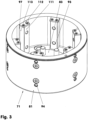
- Bodengruppe;
- Figur 4:
- Deckelgruppe mit Linearführungssystem;
- Figur 5:
- Kolben.
- Die
Figuren 1 - 5 zeigen ein Achsausgleichsmodul (10) und einige seiner Einzelteile. Derartige Achsausgleichsmodule (10) werden beispielsweise in Linearachsen von Handhabungsgeräten eingesetzt, um Bauteile mit großen Maßtoleranzen oder bei ungenauer Position zu handhaben. Das Achsausgleichsmodul (10) bildet hierbei eine Zwischenflanschbaugruppe (10), die zwischen dem letzten Gelenk des Handhabungsgeräts und beispielsweise einer Greifvorrichtung angeordnet ist. - Das Achsausgleichsmodul (10) hat ein Gehäuse (11). Dieses hat einen an einer Deckelgruppe (21) angeordneten ersten Befestigungsflansch (22) und einen an einer Bodengruppe (71) angeordneten zweiten Befestigungsflansch (72). Die beiden Befestigungsflansche (22, 72) sind beispielsweise kongruent zueinander ausgebildet, sodass z.B. die Greifvorrichtung ohne das Achsausgleichsmodul (10) am Handhabungsgerät befestigt werden kann. Im Ausführungsbeispiel sind die beiden Befestigungsflansche (22, 72) nach ISO 9409-1 gestaltet. Gemäß dieser Norm wird die Nenngröße des jeweiligen Befestigungsflansches (22; 72) nach dem Durchmesser des Teilkreises (23; 73) für seine Befestigungsschrauben (24) bezeichnet. Das in den Figuren dargestellte Achsausgleichsmodul (10) hat die Nenngröße 100. Seine Teilkreise der Befestigungsflansche (22, 72) haben einen Durchmesser von 100 Millimetern. Beispielsweise können geometrisch ähnliche Achsausgleichsmodule (10) gemäß einer geometrischen Reihe, z.B. der dezimalgeometrischen Normalzahlreihe R 10 nach DIN 323, gestaffelt sein.
- Auf dem Teilkreis (23) sind an der Deckelgruppe (21) beispielsweise sechs Befestigungsschrauben (24) und eine Zentrierbolzenaufnahme (25) angeordnet. Die Bodengruppe (71) hat auf dem Teilkreis (73) gleichen Durchmessers Gewindebohrungen (74), die z.B. mittels Verschlusseinsätzen (75) verschlossen sind sowie eine hier nicht dargestellte Zylinderbolzenaufnahme.
- An der Deckelgruppe (21) ragen die Befestigungsschrauben (24) aus der Stirnseite (12) des Achsausgleichsmoduls (10) heraus. Weiterhin sitzen auf dem Teilkreis (23) beispielsweise drei Zentrierstifte (26), die einen Führungstragring (41) an einem Deckelteil (31) zentrieren. Auf der Stirnseite (12) der Deckelgruppe (21) ist weiterhin ein Zentrierring (27) z.B. zum Zentrieren des Achsausgleichmoduls (10) am Handhabungsgerät ausgebildet.
- In der Bodengruppe (71) ist eine Zentrieraufnahme (77) ausgebildet. Dies ist beispielsweise eine Senke, deren Durchmesser 63 % des Durchmessers des Teilkreises (73) beträgt. Die Tiefe der Zentrieraufnahme (77) beträgt z.B. 6 % der Nenngröße des Achsausgleichmoduls (10). In der Zentrieraufnahme (77) sind z.B. sechs Kolbenbefestigungsschrauben (78) auf einem gemeinsamen Teilkreis angeordnet.
- Das in den Figuren dargestellte Achsausgleichsmodul (10) hat eine zylinderförmige Hüllkontur. Die Mittellinie (14) ist in der Längsrichtung (15) des Achsausgleichsmoduls (10) orientiert. Der Durchmesser der Deckelgruppe (21) beträgt z.B. das 1,4-fache der Nenngröße. In der Deckelgruppe (21) ist die Bodengruppe (71) aufgenommen, deren Durchmesser z.B. 96 % des Durchmessers der Deckelgruppe (21) beträgt. Die Höhe des ausgefahrenen Achsausgleichselements (10) entspricht z.B. der Nenngröße des Achsausgleichmoduls (10). Es ist auch denkbar, das Achsausgleichsmodul (10) mit einer quaderförmigen Hüllkontur auszubilden.
- An der Mantelfläche (28) der Deckelgruppe (21) ist ein Medienanschluss (13) angeordnet. Im Ausführungsbeispiel ist dies ein Pneumatikanschluss (13). Das Achsausgleichmodul (10) kann auch ohne Medienanschluss (13) ausgebildet sein. Weiterhin ist im Ausführungsbeispiel an der Mantelfläche (28) ein Entlüftungsanschluss (16) vorgesehen. Dieser kann ein Sieb aufweisen, um das Eindringen von Verunreinigungen zu verhindern.
- Die in der
Figur 1 dargestellte Deckelgruppe (21) trägt eine Sensoraufnahme (17) Diese ist an der Mantelfläche (28) der Deckelgruppe (21) angeordnet. In der Sensoraufnahme (17) kann ein wegabhängiger Sensor eingesetzt sein. Dies kann ein Magnetsensor, ein induktiver oder kapazitiver Sensor, etc. sein. - Der Hub des Achsausgleichmoduls (10) in der Längsrichtung (15) beträgt im Ausführungsbeispiel 15 % der Nenngröße. Als Hub des Achsausgleichsmoduls (10) ist die Änderung der in der Längsrichtung (10) orientierten Gesamtlänge bezeichnet, um die die Bodengruppe (71) relativ zur Deckelgruppe (21) verschiebbar ist. Dieser Hub ist größer oder gleich 10 % der Nenngröße des Achsausgleichmoduls (10).
- Die in der Längsrichtung (15) orientierte Höhe der Bodengruppe (71) beträgt im Ausführungsbeispiel 70 % der Nenngröße des Achsausgleichselements (10). Die Bodengruppe (71) ist topfförmig ausgebildet. Sie hat ein Bodenteil (81), den Kolben (101) und z.B. sechs Führungsklötze (111) mit Anschlagplatten (112).
- Das Bodenteil (81), vgl. die
Figuren 2 und3 , hat einen Boden (82) und eine vom Boden abstehende Wandung (91). Die Dicke des Bodens (82) und der Wandung (91) beträgt jeweils z.B. bis zu 15 % der Nenngröße des Achsausgleichsmoduls (10). Der Boden (82) hat eine ringförmige, plane Auflagefläche (83) mit einer zentralen Zentriereinsenkung (84). In dieser Auflagefläche (83) sind die Durchbrüche (85) für die Kolbenbefestigungsschrauben (78) angeordnet. Die Wandung (91) hat an ihrer Außenseite (92) z.B. 12 Durchgangsbohrungen (93) und Zentrierstiftaufnahmen (94). Beispielsweise ist jeder der Durchgangsbohrungen (93) eine Zentrierstiftaufnahme (94) zugeordnet. Jeweils zwei Durchgangsbohrungen (93) sind in der Längsrichtung (15) versetzt zueinander angeordnet. Die einzelnen Gruppen von Durchgangsbohrungen (93) und Zentrierstiftaufnahmen (94) sind in der Umfangsrichtung (18) gleichmäßig in der Wandung (91) verteilt. Am freien Ende hat die Wandung (91) an ihrer Außenseite (92) eine Ringaufnahme (95). Im zusammengebauten Achsausgleichsmodul (10) liegt in dieser Ringaufnahme (95) ein Dichtring (96). - Die Innenwandung des Bodenteils (81) hat im Bereich der Durchgangsbohrungen (93) Abflachungen (97). An diesen liegt jeweils ein Führungsklotz (111) an. Im Ausführungsbeispiel sind alle Führungsklötze (111) identisch ausgebildet und haben eine quaderförmige Gestalt. Beispielsweise beträgt ihre in der Längsrichtung (15) orientierte Höhe 55 % der Nenngröße. Ihre Breite in einer Tangentialrichtung zur Umfangsrichtung (18) beträgt z.B. 12 % der Nenngröße. Ihre Tiefe parallel zu einer radialen Ebene, in der die Mittellinie (14) liegt, beträgt im Ausführungsbeispiel 11 % der Nenngröße. Die zwei jeweils parallel zur genannten radialen Ebene liegenden Flächen des Führungsklotzes (111) werden im Folgenden Abwälzflächen (113) genannt. Diese Abwälzflächen (113) sind beispielsweise gehärtet ausgebildet und haben z.B. eine Härte zwischen 58 HRC und 64 HRC.
- Es ist denkbar, die Führungsklötze (111) prismenförmig auszubilden. Beispielsweise schließen die Abwälzflächen (113) dann in einer Normalenebene zur Längsrichtung (15) miteinander einen Winkel bis zu 120 Grad ein. Der Scheitel dieses Winkels ist in diesem Fall in Richtung der Mittellinie (14) des Achsausgleichsmoduls (10) orientiert.
- Auf der obenliegenden Stirnfläche des einzelnen Führungsklotzes (113) ist die Anschlagplatte (112) aufgeschraubt. Die einzelne Anschlagplatte (112) steht über beide Abwälzflächen (113) über. Die Oberseite der Anschlagplatten (112) ist beispielsweise bündig mit dem oberen Rand der Wandung (91).
- Auf der Auflagefläche (83) liegt ein Kolben (101) auf. Der Kolben (101) ist dort mittels der Kolbenbefestigungsschrauben (78) befestigt. Seine Unterseite hat eine Zentrierspitze (102), die bei montiertem Achsausgleichsmodul (10) in die Zentriereinsenkung (84) des Bodens (82) ragt.
- Der Kolben (101), vgl. die
Figuren 2 und5 , hat an seiner Kolbenmantelfläche (103) einen Absatz (104). Mit diesem Absatz (104) hintergreift er die Deckelgruppe (21) des Achsausgleichsmoduls (10). Oberhalb des Absatzes (104) trägt der Kolben (101) in der Darstellung derFigur 2 einen Wellendichtring (105), der bei montiertem Achsausgleichsmodul (10) an der Deckelgruppe (21) abdichtend anliegt. - Die Kolbenoberseite (106) hat einen umlaufenden Ring (107), der eine Druck- und Abstützfläche (108) begrenzt. Auf dieser Druck- und Abstützfläche (108) stützt sich in der Darstellung der
Figur 2 ein Federelement (121) ab. - Das Federelement (121) ist eine Druckfeder (121), die die Deckelgruppe (21) und die Bodengruppe (71) auseinanderdrückt. Im Ausführungsbeispiel sitzt das Federelement (121) in einem Druckraum (122), der von der Deckelgruppe (21) und der Bodengruppe (71) umschlossen wird. Beispielsweise bildet ein Hubanschlag (42) der Deckelgruppe (21) einen Ausfahranschlag (42) des Achsausgleichsmoduls (10). In der ausgefahrenen Stellung des Achsausgleichsmoduls (10) liegt der Kolben (101) mit seinem Absatz (104) am Ausfahranschlag (42) an.
- Der Druckraum (122) ist im Ausführungsbeispiel durch den Medienanschluss (13) hindurch mit einem Mediendruck beaufschlagbar. Der Mediendruck summiert sich zu dem vom Federelement (121) erzeugten Belastung der Deckelgruppe (21) und der Bodengruppe (71), sodass sich bei einer zusätzlichen Mediendruckbelastung die Steifigkeit des Achsausgleichsmoduls (10) erhöht. Bei einer Druckentlastung des Medienanschlusses (13), z.B. beim Umschalten eines vorgeschalteten Wegeventils, wird der Zusatzdruck im Druckraum (122) vermindert. Das Achsausgleichsmodul (10) wird dann nur noch mittels des Federelements (121) belastet. Zusätzlich wird Luft aus dem mittels des Dichtrings (96) begrenzten Raum außerhalb des Druckraums z.B. durch den Entlüftungsanschluss (16) verdrängt.
- Die Deckelgruppe (21), vgl. die
Figuren 2 und4 , weist das Deckelteil (31) mit einem Deckel (32) und den daran befestigten Führungstragring (41) auf. Die Oberseite des Deckels (32) bildet die oben beschriebene Stirnseite (12) der Deckelgruppe (21). Die Innenseite des Deckels (32) hat eine Federaufnahme (33). Diese begrenzt den Druckraum (122) in der Längsrichtung (15). Sie ist z.B. als kreisflächenförmige Planfläche ausgebildet. Der Deckel (32) hat an seiner Innenseite eine Führungstragringzentrierung (34). Die Führungstragringzentrierung (34) trägt einen Dichtring (35), der beispielsweise am Führungstragring (41) anliegt. - Der Führungstragring (41) hat eine zylindrische Innenwandung (43). Diese ist im unteren Bereich mittels des Ausfahranschlags (42) begrenzt. Die Außenwandung (44) des Führungstragrings (41) hat eine zylindrische Hüllkontur. Diese wird durch z.B. sechs am Umfang gleichmäßig verteilte Stollen (51) vorgegeben.
- Jeder Stollen (51) ist in der Umfangsrichtung (18) durch zwei Auflageflächen (52) begrenzt. Die einzelne Auflagefläche (52) hat eine in der Längsrichtung (15) orientierte Höhe von z.B. 55 % der Nenngröße und eine normal hierzu orientierte Breite von beispielsweise 10 % der Nenngröße. Die einzelne Auflagefläche (52) ist als Planfläche (52) ausgebildet.
- Jeweils zwei benachbarte Stollen (51) begrenzen mit ihren Auflageflächen (52) eine Führungsausnehmung (53). Bei montiertem Achsausgleichsmodul (10) sitzen jeweils ein Führungsklotz (111), zwei Linear-Wälzlagereinheiten (132) sowie zwei Abwälzbleche (135) in einer Führungsausnehmung (53). Die zwei Linear-Wälzlagereinheiten (132) bilden eine Lagergruppe (136) eines Linearführungssystems (131). Das Linearführungssystem (131) des Achsausgleichsmoduls (10) hat mindestens drei gleichartig aufgebaute Lagergruppen (136). Das in den Figuren dargestellte Achsausgleichsmodul (10) des Ausführungsbeispiels hat sechs Lagergruppen (136) mit jeweils zwei Linear-Wälzlagereinheiten (132).
- Die Auflageflächen (52) sind parallel zu den Abwälzflächen (113) der Führungsklötze (111) ausgerichtet. Im Ausführungsbeispiel sind die zueinander orientierten Auflageflächen (52) zweier benachbarter Stollen (51) parallel zueinander. Bei einer nichtparallelen Ausbildung der Abwälzflächen (113) ist der von den Auflageflächen (52) in einer Normalenebene zur Längsrichtung (15) eingeschlossene Winkel entsprechend angepasst.
- Die Abwälzbleche (135) sind Blechstreifen mit einer Dicke von bis zu 2 % der Nenngröße. Sie sind z.B. gehärtet und geschliffen ausgebildet. Jeweils ein Abwälzblech (135) überdeckt eine Auflagefläche (52) vollständig. Ein Anschlaghaken (54) und ein Auflagehaken verhindern ein Verschieben der Abwälzbleche (135).
- Zwischen jeweils einem Abwälzblech (135) und einer Abwälzfläche (113) sitzt jeweils eine Linear-Wälzlagereinheit (132) des Linearführungssystems (131). Es ist auch denkbar, zusätzlich auf der einzelnen Abwälzfläche (113) ein Abwälzblech (135) anzuordnen. Die einzelne Linear-Wälzlagereinheit (132) weist einen Wälzlagerkäfig (133) in der Bauform eines Flachkäfigs und darin drehbar gelagerte Wälzkörper (134), z.B. in der Bauform von Nadeln (134) auf. Die Länge des Wälzlagerkäfigs (133) beträgt im Ausführungsbeispiel 38 % der Nenngröße. Der Wälzlagerkäfig (133) ist beispielsweise aus einem metallischen Werkstoff, Kunststoff, etc. hergestellt. Er trägt im Ausführungsbeispiel z.B. 12 Nadeln (134), die einreihig parallel zueinander orientiert sind. Die einzelne Nadel (134) hat im dargestellten Ausführungsbeispiel eine Länge von 8 % der Nenngröße und einen Durchmesser von 1,5 % der Nenngröße. Sie besteht z.B. aus dem Werkstoff 100Cr6. Die Nadeln (134) sind ballig ausgebildet und haben beispielsweise eine Gestalt nach DIN 5402 Blatt 3 Form B.
- Die einzelne Linear-Wälzlagereinheit (132) hat eine wirksame statische Tragzahl von z.B. 2850 Newton und eine wirksame dynamische Tragzahl von beispielsweise 7350 Newton. Die wirksame statische Tragzahl der einzelnen Linear-Wälzlagereinheit (132) ist damit größer als 2000 Newton, die wirksame dynamische Tragzahl ist größer als 5000 Newton. Bezogen auf die Nenngröße des Achsausgleichsmoduls (10) ist die wirksame statische Tragzahl größer als 20 Newton pro Millimeter und die wirksame dynamische Tragzahl größer als 50 Newton pro Millimeter. Die Linear-Wälzlagereinheit (132) ist fettgeschmiert.
- Beim Zusammenbau werden beispielsweise zunächst die Führungsklötze (111) im Bodenteil (81) befestigt. In den Führungstragring (41) wird der Kolben (101) und das Federelement (121) eingesetzt. Das Deckelteil (31) wird auf den Führungstragring (41) aufgesetzt und beispielsweise temporär mittels Muttern auf den Befestigungsschrauben (24) gesichert. Zusammen mit den Linear-Wälzlagereinheiten (132) und den Abwälzblechen (135) wird diese Montageeinheit in das Bodenteil (81) eingesetzt. Der Kolben (101) wird mittels der Kolbenbefestigungsschrauben (78) am Bodenteil (81) fixiert. Für die Montage z.B. am Handhabungsgerät sind nach dem Entfernen der Verschlusseinsätze (75) die Köpfe der Befestigungsschrauben (24) zugänglich. Ein Werkzeug, z.B. eine Greifeinheit, kann an die Bodengruppe (71) angeschraubt werden. Auch eine andere Reihenfolge des Zusammenbaus ist denkbar.
- Beim Betrieb steht das Achsausgleichsmodul (10) zunächst in seiner, in den
Figuren 1 und2 dargestellten ausgefahrenen Stellung. Das Federelement (121) und gegebenenfalls im Druckraum (122) anstehender pneumatischer oder hydraulischer Druck stellen diese Stellung sicher. - Beim Auftreffen auf ein z.B. ungenau liegendes Werkstück wird die Bodengruppe (71) in Richtung der Deckelgruppe (21) belastet. Hierbei bildet im Gesamtsystem z.B. die Deckelgruppe (21) ein Festteil und die Bodengruppe (71) ein Losteil. Das Federelement (121) wird komprimiert. Das Volumen des Druckraums (122) wird vermindert. Die Dichtelemente (35, 96, 105) sichern die Bewegungsfugen gegen Druckverlust. Beispielsweise mittels des Wegsensors wird der Hub des Achsausgleichsmoduls (10) erfasst und an die Robotersteuerung übermittelt. Beim wiederholten Einsatz kann diese Information z.B. zum Einlernen der Robotersteuerung eingesetzt werden. Die bei der Hubbewegung des Achsausgleichsmoduls (10) zunehmende Steifheit verhindert eine Beschädigung des Werkzeugs und des Industrieroboters.
- Auch Kombinationen der einzelnen Ausführungsbeispiele sind denkbar.
-
- 10
- Achsausgleichsmodul, Zwischenflanschbaugruppe
- 11
- Gehäuse
- 12
- Stirnseite
- 13
- Medienanschluss, Pneumatikanschluss
- 14
- Mittellinie
- 15
- Längsrichtung
- 16
- Entlüftungsanschluss
- 17
- Sensoraufnahme
- 18
- Umfangsrichtung
- 21
- Deckelgruppe
- 22
- erster Befestigungsflansch
- 23
- Teilkreis
- 24
- Befestigungsschrauben
- 25
- Zentrierbolzenaufnahme
- 26
- Zentrierstifte
- 27
- Zentrierring
- 28
- Mantelfläche
- 31
- Deckelteil
- 32
- Deckel
- 33
- Federaufnahme
- 34
- Führungstragringzentrierung
- 35
- Dichtring, Dichtelement
- 41
- Führungstragring
- 42
- Hubanschlag, Ausfahranschlag
- 43
- Innenwandung von (41)
- 44
- Außenwandung von (41)
- 51
- Stollen
- 52
- Auflageflächen, Planfläche
- 53
- Führungsausnehmung
- 54
- Anschlaghaken
- 71
- Bodengruppe
- 72
- zweiter Befestigungsflansch
- 73
- Teilkreis
- 74
- Gewindebohrungen
- 75
- Verschlusseinsätze
- 77
- Zentrieraufnahme
- 78
- Kolbenbefestigungsschrauben
- 81
- Bodenteil
- 82
- Boden
- 83
- Auflagefläche
- 84
- Zentriereinsenkung
- 85
- Durchbrüche
- 91
- Wandung
- 92
- Außenseite
- 93
- Durchgangsbohrungen
- 94
- Zentrierstiftaufnahmen
- 95
- Ringaufnahme
- 96
- Dichtring, Dichtelement
- 97
- Abflachungen
- 101
- Kolben
- 102
- Zentrierspitze
- 103
- Kolbenmantelfläche
- 104
- Absatz
- 105
- Wellendichtring, Dichtelement
- 106
- Kolbenoberseite
- 107
- Ring
- 108
- Druck- und Abstützfläche
- 111
- Führungsklötze
- 112
- Anschlagplatten
- 113
- Abwälzflächen
- 121
- Federelement, Druckfeder
- 122
- Druckraum
- 131
- Linearführungssystem
- 132
- Lagereinheiten, Linear-Wälzlagereinheiten
- 133
- Wälzlagerkäfig, Nadelkäfig
- 134
- Wälzkörper, Nadeln
- 135
- Abwälzbleche
- 136
- Lagergruppen
Claims (14)
- Achsausgleichsmodul (10) als Zwischenflanschbaugruppe einer Linearachse mit einem Gehäuse (11), das eine Deckelgruppe (21) und eine relativ zu dieser mittels eines Federelements (121) belastete Bodengruppe (71) aufweist, dadurch gekennzeichnet,- dass die Deckelgruppe (21) und die Bodengruppe (71) relativ zueinander in einer Längsrichtung (15) mittels eines Linearführungssystems (131) geführt sind und- dass das Linearführungssystem (131) mindestens drei Lagergruppen (136) mit jeweils zwei Linear-Wälzlagereinheiten (132) aufweist.
- Achsausgleichsmodul (10) nach Anspruch 1, dadurch gekennzeichnet, dass jede der Linear-Wälzlagereinheiten (132) einen Wälzlagerkäfig (133) mit darin gelagerten zylindrischen Wälzkörpern (134) aufweist.
- Achsausgleichsmodul (10) nach Anspruch 2, dadurch gekennzeichnet, dass die Wälzkörper (134) Nadeln (134) sind.
- Achsausgleichsmodul (10) nach Anspruch 1, dadurch gekennzeichnet, dass die Bodengruppe (71) ein Bodenteil (81) und Führungsklötze (111) mit daran ausgebildeten Abwälzflächen (113) aufweist.
- Achsausgleichsmodul (10) nach Anspruch 1, dadurch gekennzeichnet, dass das Federelement (121). in einem mittels eines Druckmediums beaufschlagbaren Druckraum (122) angeordnet ist.
- Achsausgleichsmodul (10) nach Anspruch 5, dadurch gekennzeichnet, dass der Druckraum (122) mittels eines Kolbens (101) begrenzt ist.
- Achsausgleichsmodul (10) nach Anspruch 6, dadurch gekennzeichnet, dass der Kolben (101) relativ zur Deckelgruppe (21) beweglich ist und an der Bodengruppe (71) befestigt ist.
- Achsausgleichsmodul (10) nach Anspruch 7, dadurch gekennzeichnet, dass die Deckelgruppe (10) einen Hubanschlag (42) für den Kolben (101) bildet.
- Achsausgleichsmodul (10) nach Anspruch 1, dadurch gekennzeichnet, dass die Bodengruppe (71) und die Deckelgruppe (21) zueinander komplementäre Befestigungsflansche (22; 72) des Achsausgleichsmoduls (10) haben.
- Achsausgleichsmodul (10) nach Anspruch 1, dadurch gekennzeichnet, dass sein maximaler Hub mindestens 10 % seiner Nenngröße nach ISO 9409-1 beträgt.
- Achsausgleichsmodul (10) nach Anspruch 1, dadurch gekennzeichnet, dass es einen Wegsensor aufweist.
- Achsausgleichsmodul (10) nach Anspruch 1, dadurch gekennzeichnet, dass die auf seine Nenngröße bezogene wirksame dynamische Tragzahl größer ist als 20 Newton pro Millimeter der Nenngröße.
- Achsausgleichsmodul (10) nach Anspruch 1, dadurch gekennzeichnet, dass das Linearführungssystem (131) mittels eines eine äußere Bewegungsfuge der Deckelgruppe (21) und der Bodengruppe (71) abdichtenden Dichtrings (96) abgedichtet ist.
- Industrieroboter mit einem Achsausgleichsmodul (10) nach Anspruch 1.
Applications Claiming Priority (1)
| Application Number | Priority Date | Filing Date | Title |
|---|---|---|---|
| DE202022002157.7U DE202022002157U1 (de) | 2022-09-30 | 2022-09-30 | Achsausgleichsmodul |
Publications (3)
| Publication Number | Publication Date |
|---|---|
| EP4345327A1 true EP4345327A1 (de) | 2024-04-03 |
| EP4345327B1 EP4345327B1 (de) | 2025-10-15 |
| EP4345327C0 EP4345327C0 (de) | 2025-10-15 |
Family
ID=84784314
Family Applications (1)
| Application Number | Title | Priority Date | Filing Date |
|---|---|---|---|
| EP23000132.3A Active EP4345327B1 (de) | 2022-09-30 | 2023-09-27 | Achsausgleichsmodul |
Country Status (2)
| Country | Link |
|---|---|
| EP (1) | EP4345327B1 (de) |
| DE (1) | DE202022002157U1 (de) |
Citations (2)
| Publication number | Priority date | Publication date | Assignee | Title |
|---|---|---|---|---|
| DE102013220148B3 (de) | 2013-10-04 | 2015-02-26 | Schunk Gmbh & Co. Kg Spann- Und Greiftechnik | Ausgleichseinheit und Ausgleichssystem |
| DE102016108257A1 (de) * | 2016-05-03 | 2017-11-09 | Krones Ag | Delta-Roboter mit Teleskopstange |
-
2022
- 2022-09-30 DE DE202022002157.7U patent/DE202022002157U1/de active Active
-
2023
- 2023-09-27 EP EP23000132.3A patent/EP4345327B1/de active Active
Patent Citations (2)
| Publication number | Priority date | Publication date | Assignee | Title |
|---|---|---|---|---|
| DE102013220148B3 (de) | 2013-10-04 | 2015-02-26 | Schunk Gmbh & Co. Kg Spann- Und Greiftechnik | Ausgleichseinheit und Ausgleichssystem |
| DE102016108257A1 (de) * | 2016-05-03 | 2017-11-09 | Krones Ag | Delta-Roboter mit Teleskopstange |
Also Published As
| Publication number | Publication date |
|---|---|
| DE202022002157U1 (de) | 2022-12-16 |
| EP4345327B1 (de) | 2025-10-15 |
| EP4345327C0 (de) | 2025-10-15 |
Similar Documents
| Publication | Publication Date | Title |
|---|---|---|
| EP4448978B1 (de) | Brems- und/oder klemmvorrichtung mit kolbenbelastbarem scheibenelement | |
| DE3446495C2 (de) | Kreuzgelenk für eine Gelenkwelle | |
| EP2683961B1 (de) | Durch materialverdrängung vorspannbare buchse und mit dieser buchse ausgestattetes lager | |
| DE102009041907B4 (de) | Brems- und/oder Klemmvorrichtung mit formsteifem Zentralkörper | |
| DE102011054063B4 (de) | Antriebsvorrichtung für ein Stützteil zum Abstützen eines Werkstücks | |
| DE102021114663A1 (de) | Kopplungsmechanismus für roboter-werkzeugwechsler mit erhöhter torsionssteifigkeit und reduziertem spiel | |
| DE2643575C2 (de) | Wellenkupplung | |
| EP2691192B1 (de) | Radialpresse | |
| EP4345327B1 (de) | Achsausgleichsmodul | |
| EP3403758A1 (de) | Einstellbarer aufsatzadapter | |
| DE102021125551B4 (de) | Pressenelement einer Presse, Pressentisch sowie Presse | |
| DE102020002706A1 (de) | Ringklemmelement mit Vielkeilgetriebe | |
| DE102014211272B4 (de) | Wellenkupplung | |
| DE102024001262A1 (de) | Lagerungssystem für ein Greifersystem | |
| DE102018204539A1 (de) | Toroidales Rollenlager | |
| EP0070480A2 (de) | Verfahren und Vorrichtung zur Druckplattenlagerung in Werkstoffprüfmaschinen | |
| DE102011007494A1 (de) | Konzept zum Bereitstellen einer Anlageschulter in einem zylinderförmigen Lagergehäuse | |
| DE102009037392A1 (de) | Wälzlageranordnung zu Axial- und/oder Radiallagerung mit Lagerentlastungsmitteln | |
| DE102020201475A1 (de) | Wälzlager mit einem Federsystem und Verfahren zum Messen des axialen Spiels des Wälzlagers | |
| DE102014015869A1 (de) | Kraftmessvorrichtung | |
| DE102019115309A1 (de) | Lagerscheibe für ein Axialrollenlager | |
| DE102016214434B3 (de) | Kraft-Moment-Sensor für eine Robotikeinheit | |
| EP0039043B1 (de) | Axial spielfreies Radialwälzlager | |
| DE4333487C1 (de) | Massestapel für Kraft-Kontrollmeßmaschinen mit direkter Massewirkung | |
| WO2010049328A2 (de) | Lageranordnung einer vertikal stehenden antriebsspindel |
Legal Events
| Date | Code | Title | Description |
|---|---|---|---|
| PUAI | Public reference made under article 153(3) epc to a published international application that has entered the european phase |
Free format text: ORIGINAL CODE: 0009012 |
|
| STAA | Information on the status of an ep patent application or granted ep patent |
Free format text: STATUS: THE APPLICATION HAS BEEN PUBLISHED |
|
| AK | Designated contracting states |
Kind code of ref document: A1 Designated state(s): AL AT BE BG CH CY CZ DE DK EE ES FI FR GB GR HR HU IE IS IT LI LT LU LV MC ME MK MT NL NO PL PT RO RS SE SI SK SM TR |
|
| STAA | Information on the status of an ep patent application or granted ep patent |
Free format text: STATUS: REQUEST FOR EXAMINATION WAS MADE |
|
| 17P | Request for examination filed |
Effective date: 20240925 |
|
| RBV | Designated contracting states (corrected) |
Designated state(s): AL AT BE BG CH CY CZ DE DK EE ES FI FR GB GR HR HU IE IS IT LI LT LU LV MC ME MK MT NL NO PL PT RO RS SE SI SK SM TR |
|
| GRAP | Despatch of communication of intention to grant a patent |
Free format text: ORIGINAL CODE: EPIDOSNIGR1 |
|
| STAA | Information on the status of an ep patent application or granted ep patent |
Free format text: STATUS: GRANT OF PATENT IS INTENDED |
|
| INTG | Intention to grant announced |
Effective date: 20250507 |
|
| GRAS | Grant fee paid |
Free format text: ORIGINAL CODE: EPIDOSNIGR3 |
|
| GRAA | (expected) grant |
Free format text: ORIGINAL CODE: 0009210 |
|
| STAA | Information on the status of an ep patent application or granted ep patent |
Free format text: STATUS: THE PATENT HAS BEEN GRANTED |
|
| AK | Designated contracting states |
Kind code of ref document: B1 Designated state(s): AL AT BE BG CH CY CZ DE DK EE ES FI FR GB GR HR HU IE IS IT LI LT LU LV MC ME MK MT NL NO PL PT RO RS SE SI SK SM TR |
|
| REG | Reference to a national code |
Ref country code: GB Ref legal event code: FG4D Free format text: NOT ENGLISH Ref country code: CH Ref legal event code: F10 Free format text: ST27 STATUS EVENT CODE: U-0-0-F10-F00 (AS PROVIDED BY THE NATIONAL OFFICE) Effective date: 20251015 |
|
| REG | Reference to a national code |
Ref country code: DE Ref legal event code: R096 Ref document number: 502023001968 Country of ref document: DE |
|
| REG | Reference to a national code |
Ref country code: IE Ref legal event code: FG4D Free format text: LANGUAGE OF EP DOCUMENT: GERMAN |
|
| U01 | Request for unitary effect filed |
Effective date: 20251111 |
|
| U07 | Unitary effect registered |
Designated state(s): AT BE BG DE DK EE FI FR IT LT LU LV MT NL PT RO SE SI Effective date: 20251117 |
|
| PG25 | Lapsed in a contracting state [announced via postgrant information from national office to epo] |
Ref country code: ES Free format text: LAPSE BECAUSE OF FAILURE TO SUBMIT A TRANSLATION OF THE DESCRIPTION OR TO PAY THE FEE WITHIN THE PRESCRIBED TIME-LIMIT Effective date: 20251015 |
|
| PG25 | Lapsed in a contracting state [announced via postgrant information from national office to epo] |
Ref country code: NO Free format text: LAPSE BECAUSE OF FAILURE TO SUBMIT A TRANSLATION OF THE DESCRIPTION OR TO PAY THE FEE WITHIN THE PRESCRIBED TIME-LIMIT Effective date: 20260115 |
|
| PG25 | Lapsed in a contracting state [announced via postgrant information from national office to epo] |
Ref country code: HR Free format text: LAPSE BECAUSE OF FAILURE TO SUBMIT A TRANSLATION OF THE DESCRIPTION OR TO PAY THE FEE WITHIN THE PRESCRIBED TIME-LIMIT Effective date: 20251015 |
|
| PG25 | Lapsed in a contracting state [announced via postgrant information from national office to epo] |
Ref country code: RS Free format text: LAPSE BECAUSE OF FAILURE TO SUBMIT A TRANSLATION OF THE DESCRIPTION OR TO PAY THE FEE WITHIN THE PRESCRIBED TIME-LIMIT Effective date: 20260115 |
|
| PG25 | Lapsed in a contracting state [announced via postgrant information from national office to epo] |
Ref country code: IS Free format text: LAPSE BECAUSE OF FAILURE TO SUBMIT A TRANSLATION OF THE DESCRIPTION OR TO PAY THE FEE WITHIN THE PRESCRIBED TIME-LIMIT Effective date: 20260215 |
|
| PG25 | Lapsed in a contracting state [announced via postgrant information from national office to epo] |
Ref country code: PL Free format text: LAPSE BECAUSE OF FAILURE TO SUBMIT A TRANSLATION OF THE DESCRIPTION OR TO PAY THE FEE WITHIN THE PRESCRIBED TIME-LIMIT Effective date: 20251015 |
|
| PG25 | Lapsed in a contracting state [announced via postgrant information from national office to epo] |
Ref country code: SM Free format text: LAPSE BECAUSE OF FAILURE TO SUBMIT A TRANSLATION OF THE DESCRIPTION OR TO PAY THE FEE WITHIN THE PRESCRIBED TIME-LIMIT Effective date: 20251015 |
|
| PG25 | Lapsed in a contracting state [announced via postgrant information from national office to epo] |
Ref country code: CZ Free format text: LAPSE BECAUSE OF FAILURE TO SUBMIT A TRANSLATION OF THE DESCRIPTION OR TO PAY THE FEE WITHIN THE PRESCRIBED TIME-LIMIT Effective date: 20251015 |
|
| PG25 | Lapsed in a contracting state [announced via postgrant information from national office to epo] |
Ref country code: SK Free format text: LAPSE BECAUSE OF FAILURE TO SUBMIT A TRANSLATION OF THE DESCRIPTION OR TO PAY THE FEE WITHIN THE PRESCRIBED TIME-LIMIT Effective date: 20251015 |