EP4345263A2 - Center pivot latched deactivating rocker arm - Google Patents
Center pivot latched deactivating rocker arm Download PDFInfo
- Publication number
- EP4345263A2 EP4345263A2 EP24157830.1A EP24157830A EP4345263A2 EP 4345263 A2 EP4345263 A2 EP 4345263A2 EP 24157830 A EP24157830 A EP 24157830A EP 4345263 A2 EP4345263 A2 EP 4345263A2
- Authority
- EP
- European Patent Office
- Prior art keywords
- latch
- arm
- cam
- lost motion
- valve
- Prior art date
- Legal status (The legal status is an assumption and is not a legal conclusion. Google has not performed a legal analysis and makes no representation as to the accuracy of the status listed.)
- Pending
Links
Images


Classifications
-
- F—MECHANICAL ENGINEERING; LIGHTING; HEATING; WEAPONS; BLASTING
- F01—MACHINES OR ENGINES IN GENERAL; ENGINE PLANTS IN GENERAL; STEAM ENGINES
- F01L—CYCLICALLY OPERATING VALVES FOR MACHINES OR ENGINES
- F01L1/00—Valve-gear or valve arrangements, e.g. lift-valve gear
- F01L1/12—Transmitting gear between valve drive and valve
- F01L1/18—Rocking arms or levers
- F01L1/181—Centre pivot rocking arms
-
- F—MECHANICAL ENGINEERING; LIGHTING; HEATING; WEAPONS; BLASTING
- F01—MACHINES OR ENGINES IN GENERAL; ENGINE PLANTS IN GENERAL; STEAM ENGINES
- F01L—CYCLICALLY OPERATING VALVES FOR MACHINES OR ENGINES
- F01L13/00—Modifications of valve-gear to facilitate reversing, braking, starting, changing compression ratio, or other specific operations
- F01L13/0005—Deactivating valves
-
- F—MECHANICAL ENGINEERING; LIGHTING; HEATING; WEAPONS; BLASTING
- F01—MACHINES OR ENGINES IN GENERAL; ENGINE PLANTS IN GENERAL; STEAM ENGINES
- F01L—CYCLICALLY OPERATING VALVES FOR MACHINES OR ENGINES
- F01L1/00—Valve-gear or valve arrangements, e.g. lift-valve gear
- F01L1/12—Transmitting gear between valve drive and valve
- F01L1/18—Rocking arms or levers
- F01L2001/186—Split rocking arms, e.g. rocker arms having two articulated parts and means for varying the relative position of these parts or for selectively connecting the parts to move in unison
-
- F—MECHANICAL ENGINEERING; LIGHTING; HEATING; WEAPONS; BLASTING
- F01—MACHINES OR ENGINES IN GENERAL; ENGINE PLANTS IN GENERAL; STEAM ENGINES
- F01L—CYCLICALLY OPERATING VALVES FOR MACHINES OR ENGINES
- F01L1/00—Valve-gear or valve arrangements, e.g. lift-valve gear
- F01L1/46—Component parts, details, or accessories, not provided for in preceding subgroups
- F01L2001/467—Lost motion springs
-
- F—MECHANICAL ENGINEERING; LIGHTING; HEATING; WEAPONS; BLASTING
- F01—MACHINES OR ENGINES IN GENERAL; ENGINE PLANTS IN GENERAL; STEAM ENGINES
- F01L—CYCLICALLY OPERATING VALVES FOR MACHINES OR ENGINES
- F01L13/00—Modifications of valve-gear to facilitate reversing, braking, starting, changing compression ratio, or other specific operations
- F01L13/0005—Deactivating valves
- F01L2013/001—Deactivating cylinders
-
- F—MECHANICAL ENGINEERING; LIGHTING; HEATING; WEAPONS; BLASTING
- F01—MACHINES OR ENGINES IN GENERAL; ENGINE PLANTS IN GENERAL; STEAM ENGINES
- F01L—CYCLICALLY OPERATING VALVES FOR MACHINES OR ENGINES
- F01L2305/00—Valve arrangements comprising rollers
Definitions
- This application provides latched center pivot (type III) rocker arms that can switch between activated and deactivated configurations.
- Center pivot rocker arms also called “type III” rocker arms, comprise a cam interface at a cam end and a valve interface at a valve end. In-between, a rocker shaft bore can connect to pivot around a rocker shaft. Hence the name “center pivot.”
- This type of rocker arm is popular in vehicles and it is desired to provide options that enable switching between variable valve actuation ("WA”) functions.
- WA variable valve actuation
- the methods and devices disclosed herein improves the art by way of center pivot (type III) rocker arms that can switch between activated and deactivated configurations to enable switching between variable valve actuation ("VVA”) functions.
- VVA variable valve actuation
- the rocker arm in an activated configuration, can transfer a first valve lift profile to engine valves.
- the rocker arm In a deactivated configuration, can transfer a second valve lift profile.
- the second valve lift profile can be a zero lift profile, also known as a lost motion profile.
- the lost motion profile can facilitate, for example, cylinder deactivation ("CDA”) engine operation.
- a rocker arm can comprise a cam arm, a valve arm, a lost motion spring biasing them apart, and a latch assembly.
- the rocker arm can comprise a cam arm comprising a cam interface at a first cam arm end, a spring pressing area at or near a second cam arm end, a cam arm body between the first cam arm end and the second cam arm end, and a pivot axle connection in the cam arm body.
- the valve arm can comprise a valve arm body.
- the valve arm body can comprise a rocker shaft bore, a latch socket, a pivot axle mounting area connected to the pivot axle connection by a pivot axle, and a lost motion spring mount.
- a valve arm neck can extend from the valve arm body.
- a head can be connected to the neck. The head can be configured to interface directly or indirectly with an engine valve.
- the lost motion spring can be biased between the lost motion spring mount and the spring pressing area.
- the latch assembly can be in the latch socket.
- the latch assembly can comprise a pair of deactivatable latches configured to protrude out of the latch socket in an activated configuration to impede travel of the cam arm with respect to the lost motion spring and configured to collapse into the latch socket in a deactivated configuration to enable the second cam arm end to act on the lost motion spring.
- the rocker arm can comprise a cam arm comprising a cam interface at a first cam arm end, a spring pressing area at or near a second cam arm end, a cam arm body between the first cam arm end and the second cam arm end, and a pivot axle connection in the cam arm body.
- the valve arm can comprise a valve arm body.
- the valve arm body can comprise a rocker shaft bore, a pivot axle mounting area connected to the pivot axle connection by a pivot axle, and a lost motion spring mount.
- a valve arm neck can extend from the valve arm body.
- a latch socket can be in the valve arm neck.
- a head can be connected to the neck, the head configured to interface directly or indirectly with an engine valve.
- a lost motion spring can be biased between the lost motion spring mount toward the spring pressing area.
- the latch assembly can be in the latch socket.
- the latch assembly can comprise a deactivatable latch configured to protrude out of the latch socket in a first configuration to impede motion of the cam arm and configured to collapse in the latch socket in a second configuration so that the second cam arm end is movable to collapse the lost motion spring.
- FIGS 1A & 2A provide alternative rocker arms comprising over-valve mechanical latch assemblies and a pivoting arm arrangement. These rocker arms comprise a midline bisecting the rocker shaft bore. It can be said that a pivot axle, a lost motion spring, and a latch socket are above the midline and a cam interface is below the midline. The latch assembly position can impact forces on the valve actuation.
- Figure 5 provides an alternative deactivating rocker arm.
- the pivoting arm arrangement comprises a midline bisecting the rocker shaft bore, wherein the pivot axle and the lost motion spring are above the midline and wherein the cam interface and the latch assembly are below the midline.
- this configuration there can be provided a three point interaction between the location of the latch assembly, rocker shaft, and pivot axle that can be optimized to change the stress levels on the latch assembly.
- the lost motion spring 680, 400, 401 is between the pivot axle 40 and the head 665, 270.
- the latch socket is between the lost motion spring 401 and the pivot axle 40.
- the lost motion spring 400 is between the latch socket and the pivot axle 40.
- a deactivating type III (center pivot) rocker arm can be comprised of two members, comprising a cam arm 100 and a valve arm 200, 201, and a mechanical latch assembly 500, 550, 600, 700.
- the cam arm 100 can be configured to pivot about a pivot axle 40 and to selectively transfer the motion of a cam to the valve arm 200 through the mechanical latch assembly 500, 550, 600.
- the rocker arm 1, 2 is capable of deactivating valve motion in a type III valvetrain.
- the deactivating type III (center pivot) rocker arm 1, 2 can be comprised of two members, comprising a cam arm 100 and a valve arm 200, 201, and a mechanical latch assembly 500, 550, 600, 700.
- the first member can be the valve side arm 200, 201 featuring a pivot (usually a rocker shaft bore 230 for a rocker shaft), a mechanical latching assembly 500, 550, 600, 700 connecting the first member to the second member, and either an HLA 70 or mechanical lash adjustment screw that will interface with a valve or valve bridge.
- the second member can comprise or consist of cam arm 100.
- a cam interface area can comprise a roller 10 and roller axle 9 for interfacing with a cam on a camshaft.
- a second cam arm end 150 of the cam arm 100 can comprise a latch interface for interfacing with a mechanical latch assembly.
- a pivot axle 40 can connect the first and second members allowing the second member to pivot in lost motion when the latch assembly of the first member is disengaged.
- a lost motion spring 400, 401 can be configured to bias the two members apart from each other.
- the lost motion spring 400, 401 maintains dynamic control of the second member as it pivots about the pivot axle 40 when the mechanical latch assembly 500, 550, 600, 700 is disengaged.
- the mechanical latch assembly when engaged, translates the motion of the second member to the first member. When disengaged, the mechanical latch assembly is configured to allow the second member to move freely about the pivot axle 40.
- the latch assembly can be oriented in multiple ways according to Figures 1A , 2A, 3, 4 , & 6 and can be hydraulically or mechanically actuated to switch between an activated configuration (engaged) and a deactivated configuration (disengaged).
- FIGS 2A & 6 a dual latch configuration is shown for the type III deactivating rocker arm.
- the rocker arms 1, 2, 3, can be cylinder deactivation ("CDA") rocker arms for a Type III (center pivot) valvetrain.
- CDA cylinder deactivation
- a single latch pin deactivatable latch 501 can have high contact stresses where the latch pin and rocker arm body meet, it can be possible to spread the load over two latch pins (deactivatable latches 60 or 701) to reduce the contact stresses significantly. Locating the two deactivatable latches 60 or 701 to collapse inward near the bearing axle 9 requires two oil feeds 693, 694 within the rocker arm body 666. The two oil feeds 694, 694 can originate from the rocker shaft bore 663 at a central location 693 and branch within the rocker arm body.
- a deactivating center pivot rocker arm 1, 2 can comprise a valve arm 200, 201 comprising a pivot such as a rocker shaft bore 230, a mechanical latching mechanism such as one of latch assemblies 500, 550, 600, 700, and either an HLA 70 or mechanical lash adjustment screw configured to interface with a valve or a valve bridge such as through an elephant foot (e-foot) extending from the head 270 of the valve arm 200, 201.
- a second member comprises a cam arm 100.
- Such cam arm 100 can comprise a roller 10 and a roller axle 9 for interfacing with a camshaft.
- a second cam arm end 150 can form a latch interface such as a ledge for interfacing with the mechanical latch in the form of latch assembly 500.
- the mechanical latch in the form of mechanical latch assembly 500 selectively mechanically connects the first member to the second member as by the ledge pressing on the protruding deactivatable latch 501.
- second cam arm end 150 comprises extensions 160 to mechanically connect the first member to the second member, as by extensions 160 pressing on protruding deactivatable latches 60, 90, or 701.
- a pivot axle 40 can connect the first and second members such that the second member pivots in lost motion when the deactivatable latch mechanism(s) of the first member is disengaged and collapsed into a latch socket in a deactivated configuration.
- a lost motion spring 400, 401 can be configured to bias the first and second members apart from each other.
- the lost motion spring maintains dynamic control of the second member as it pivots about the pivot axle 40 when the mechanical latch assembly is disengaged.
- the mechanical latch assembly 500, 550, 600, 700 when engaged in an activated configuration, translates the motion of the second member to the first member.
- the mechanical latch assembly is configured to allow the second member to move freely about the pivot axle 40.
- the pivot axle can be omitted, and the pivot can be freely about the rocker shaft bore 230 as by extending a portion of the cam arm body 110 to wrap around the rocker shaft bore 230.
- the pivot comprises the rocker shaft bore.
- the mechanical latch assemblies 500, 550, 600, 700 are shown as hydraulically actuated, but can alternatively be mechanically actuated to switch between an engaged position (activated configuration) and a disengaged position (deactivated configuration).
- a rocker arm for a type III valvetrain can alternatively comprise a cam arm 675 comprising a first cam arm end 673 comprising a cam interface such as a roller 10 on a bearing axle 9.
- the bearing axle 9 can be mounted in bores 679 in the first cam arm end 673.
- a roller bearing 10 can be mounted on a bearing axle 9 in the bearing axle bores 679 between the first and second segments 675, 676.
- a second cam arm end 672 can comprise a spring pressing area in the form of a socket for mounting a lost motion spring 680.
- a cam arm body 670 can be hollow to comprise first and second segments extending therefrom. The first and second segments can comprise first and second latch extension 651, 652. Second latch extension 652 is shown in broken lines in Figure 5 .
- the first and second segments can comprise the bearing axle bores 679.
- the first and second segments 675, 676 can comprise pivot axle connections for receiving pivot axle 40.
- Pivot axle 40 can be retained by clips, for example.
- Latch extensions 651, 652 can comprise opposed first and second latch ports 677, 678.
- a valve arm 660 can comprise a lost motion spring mount 662 in the form of a second socket in valve side body 666.
- a 663 rocker shaft bore can be formed so that a branched oil feed extends from the rocker shaft bore 663 to the latch socket 690.
- the oil feed comprising a first oil branch forming oil port 693 and a second oil branch forming oil port 694, the oil ports spreading from a central hole 664.
- a latch assembly 700 can be configured in the latch socket 690.
- the latch socket 690 can comprise a center wall 691 dividing the latch socket into a first half 696 and a second half 695.
- the latch assembly 700 comprises a pair of return springs 704 biased against respective sides of the center wall 691.
- the pair of return springs bias the pair of deactivatable latches 701, 702 apart so that the latches protrude out through first and second latch ports 677, 678 when in the activated configuration.
- the at least one oil port comprising the pair of oil ports 693, 694 supplies pressurized oil to the divided latch socket to collapse the pair of deactivatable latches.
- the divided latch socket can comprise plugs 703 so that first and second plugs surround the first and second deactivatable latches 701, 702.
- the plugs 703 can seat in the latch socket 690 to fluid seal the deactivatable latches and the latch socket 690.
- the rocker arm 2, 3 can comprise a cam arm 100, 670 comprising a cam interface at a first cam arm end 102, 673.
- Cam interface can be a tappet or roller bearing 10.
- the valve arm 201, 660 can comprise a valve arm body 284, 666.
- the valve arm body 284, 666 can comprise a rocker shaft bore 230, 663, a latch socket 244, 690, a pivot axle mounting area 204 connected to the pivot axle connection 104 by a pivot axle 40, and a lost motion spring mount 243, 662 such as a socket.
- a valve arm neck 281, 661 can extend from the valve arm body 284, 666.
- a head 270, 665 can be connected to the neck 281, 661.
- the head 270, 665 can be configured to interface directly or indirectly with an engine valve as by an e-foot or valve bridge, a capsule, or the like.
- the lost motion spring 401, 680 can be biased between the lost motion spring mount 243, 672 and the spring pressing area 140, 662.
- the latch assembly 550, 600, 700 can be in the latch socket 244, 690.
- the latch assembly can comprise a pair of deactivatable latches 66, 91, or 701, 702 configured to protrude out of the latch socket 244, 690 in an activated configuration to impede travel of the cam arm 100, 670 with respect to the lost motion spring 401, 680 and configured to collapse into the latch socket in a deactivated configuration to enable the second cam arm end 150, 672 to act on the lost motion spring 401, 680.
- the cam arm 100 can collapse the lost motion spring 401. It is possible to collapse or scissor apart the lost motion spring 680.
- At least one oil port 253, 260, 255, 664 extends from the rocker shaft bore, 230, 663.
- the at least one oil port is connected to the latch socket 252, 244, 690 to configure the deactivatable latches 66, 91, or 701, 702 in one of the activated configuration or the deactivated configuration.
- the latch assembly 600 comprise a center spring 65 biasing the pair of deactivatable latches 66 apart.
- the at least one oil port comprises a pair of oil ports 260 configured to supply pressurized oil to collapse the pair of deactivatable latches 66 into the latch socket by compressing the center spring 65.
- Each deactivatable latch 66 can comprise a spring cup 63, a seat portion 61, and a latch pin 64. Pressurized oil to gland 233 from rocker shaft bore 230 travels the oil ports 260. The pressure pushes the seat portions 61 to slide in the cavity 256 and collapse the center spring 65.
- the timing of the deactivation can be controlled by including a controlled oil port 62 out of the latch socket.
- a size of the controlled oil port 62 controls how fast and in what latch position oil can leak out and depressurize the deactivatable latches 66 to return to their protruding positions, as biased by the center spring 65.
- the latch socket can comprise a retention wall 2571 and the controlled oil port 62 can be through the retention wall 2571.
- the latch socket can comprise a latch port 259 on a first side 257 configured so that a first one of the pair of deactivatable latches protrudes out of the valve body.
- the latch socket can comprise a plug 290 on a second side 258 configured so that a second one of the pair of deactivatable latches protrudes out of the valve body.
- the rocker arms can alternatively comprise a latch assembly 700 of Figure 5 & 6 , meaning that any of rocker arms 2 & 3 can comprise any one of the dual latch assemblies 550, 600, 700.
- the latch socket 690 can comprise a center wall 691 dividing the latch socket 690.
- the latch assembly 700 can comprise a pair of return springs 704 biased against respective sides of the center wall 691, the pair of return springs 704 biasing the pair of deactivatable latches 701, 702 apart.
- the at least one oil port comprises a pair of oil ports 693, 694 configured to supply pressurized oil to the divided latch socket to collapse the pair of deactivatable latches 701, 702.
- the latch socket 690 can comprise a first latch plug 703 on a first side configured so that a first one 701 of the pair of deactivatable latches protrudes out of the valve body 666.
- the latch socket can comprise a second latch plug 703 on a second side configured so that a second one 702 of the pair of deactivatable latches protrudes out of the valve body 666.
- the valve body can comprise a latch extension 699 to position the latch assembly 700 below the midline of the rocker arm and adjacent the cam interface. In this configuration there can be provided a three point interaction between the location of the latch assembly 700, rocker shaft in rocker shaft bore 663, and pivot axle 40 that can be optimized to change the stress levels on the latch assembly 700.
- the latch assembly 550 comprises an alternative configuration.
- the latch socket comprises a first latch port 259 on a first side configured so that a first one of the pair of deactivatable latches 91 protrudes out of the valve body.
- the latch socket comprises a second latch port 259 on a second side configured so that a second one of the pair of deactivatable latches 91 protrudes out of the valve body.
- a movable member 900 reciprocates in the latch socket cavity 258 between a top half 257 of the latch socket and a bottom half 256.
- the movable member 900 comprises a member body 90 and a pair of latch grooves 92 connected to the member body 90.
- a member return spring 99 is biased between a the movable member 900 and the cam arm body 110.
- the member return spring 99 can be secured in a spring cup 94 or, like the lost motion springs 400, 401, 680, the member return spring 99 can be secured by another mounting feature, such as a peg, socket, lip, or groove or the like.
- the movable member 900 is controllable to align the member body 90 to protrude the pair of deactivatable latches 91 out of the latch socket in the activated configuration and movable member 900 is controllable to align the pair of latch grooves 92 to collapse the pair of deactivatable latches 91 into the latch socket.
- the rocker arm can comprises an one oil port 255 extending from the rocker shaft bore 230, 663, the at least one oil port 255 connected to the latch socket to control the movable member 900 to configure the deactivatable latches 91 in one of the activated configuration or the deactivated configuration.
- the rocker arm 1 can comprise a cam arm 100 comprising a cam interface at a first cam arm end 102, a spring pressing area 140 at or near a second cam arm end 150, a cam arm body 110 between the first cam arm end 102 and the second cam arm end 150, and a pivot axle connection 104 in the cam arm body 110.
- the valve arm 200 can comprise a valve arm body 283.
- the valve arm body 283 can comprise a rocker shaft bore 230, a pivot axle mounting area 204 connected to the pivot axle connection 104 by a pivot axle 40, and a lost motion spring mount 241.
- the lost motion spring mount 241 can comprise a socket or the like.
- a valve arm neck 280 can extend from the valve arm body 283.
- a latch socket 252 can be in the valve arm neck 280.
- a head 270 can be connected to the neck 280, the head 270 configured to interface directly or indirectly with an engine valve.
- a lost motion spring 400 can be biased between the lost motion spring mount 241 toward the spring pressing area 140.
- the latch assembly 500 can be in the latch socket 252.
- the latch assembly 500 can comprise a deactivatable latch 501 configured to protrude out of the latch socket 252 in a first configuration to impede motion of the cam arm 100 and configured to collapse in the latch socket 252 in a second configuration so that the second cam arm end 150 is movable to collapse the lost motion spring 400.
- the latch assembly 500 can comprise the deactivatable latch 501 biased to protrude by a return spring 505 at a spring mount such as spring cup 504.
- the deactivatable latch 501 can be held in the latch socket cavity 252 by a frit or plug 251.
- the spring cup 504 can form a seal against a wall 250 of the cavity 252 so that the deactivatable latch 501 can slide against the wall 250 when pressurized oil is supplied by oil port 253. Additional walls can be included to encase the latch assembly 500 in the latch socket.
- a latch pin 503 of deactivatable latch 501 can restrict a ledge on second cam arm end 150 when it protrudes, and the ledge can pass the latch pin 503 when the oil pressure collapses the deactivatable latch 501 in the latch socket.
Landscapes
- Engineering & Computer Science (AREA)
- Mechanical Engineering (AREA)
- General Engineering & Computer Science (AREA)
- Valve Device For Special Equipments (AREA)
- Valve-Gear Or Valve Arrangements (AREA)
Abstract
Description
- This application provides latched center pivot (type III) rocker arms that can switch between activated and deactivated configurations.
- Center pivot rocker arms, also called "type III" rocker arms, comprise a cam interface at a cam end and a valve interface at a valve end. In-between, a rocker shaft bore can connect to pivot around a rocker shaft. Hence the name "center pivot." This type of rocker arm is popular in vehicles and it is desired to provide options that enable switching between variable valve actuation ("WA") functions.
- The methods and devices disclosed herein improves the art by way of center pivot (type III) rocker arms that can switch between activated and deactivated configurations to enable switching between variable valve actuation ("VVA") functions. For example, in an activated configuration, the rocker arm can transfer a first valve lift profile to engine valves. In a deactivated configuration, the rocker arm can transfer a second valve lift profile. The second valve lift profile can be a zero lift profile, also known as a lost motion profile. The lost motion profile can facilitate, for example, cylinder deactivation ("CDA") engine operation.
- A rocker arm can comprise a cam arm, a valve arm, a lost motion spring biasing them apart, and a latch assembly.
- In a first instance, the rocker arm can comprise a cam arm comprising a cam interface at a first cam arm end, a spring pressing area at or near a second cam arm end, a cam arm body between the first cam arm end and the second cam arm end, and a pivot axle connection in the cam arm body. The valve arm can comprise a valve arm body. The valve arm body can comprise a rocker shaft bore, a latch socket, a pivot axle mounting area connected to the pivot axle connection by a pivot axle, and a lost motion spring mount. A valve arm neck can extend from the valve arm body. A head can be connected to the neck. The head can be configured to interface directly or indirectly with an engine valve. The lost motion spring can be biased between the lost motion spring mount and the spring pressing area. The latch assembly can be in the latch socket. The latch assembly can comprise a pair of deactivatable latches configured to protrude out of the latch socket in an activated configuration to impede travel of the cam arm with respect to the lost motion spring and configured to collapse into the latch socket in a deactivated configuration to enable the second cam arm end to act on the lost motion spring.
- In a second instance, the rocker arm can comprise a cam arm comprising a cam interface at a first cam arm end, a spring pressing area at or near a second cam arm end, a cam arm body between the first cam arm end and the second cam arm end, and a pivot axle connection in the cam arm body. The valve arm can comprise a valve arm body. The valve arm body can comprise a rocker shaft bore, a pivot axle mounting area connected to the pivot axle connection by a pivot axle, and a lost motion spring mount. A valve arm neck can extend from the valve arm body. A latch socket can be in the valve arm neck. A head can be connected to the neck, the head configured to interface directly or indirectly with an engine valve. A lost motion spring can be biased between the lost motion spring mount toward the spring pressing area. The latch assembly can be in the latch socket. The latch assembly can comprise a deactivatable latch configured to protrude out of the latch socket in a first configuration to impede motion of the cam arm and configured to collapse in the latch socket in a second configuration so that the second cam arm end is movable to collapse the lost motion spring.
- Additional objects and advantages will be set forth in part in the description which follows, and in part will be obvious from the description, or may be learned by practice of the disclosure. The objects and advantages will also be realized and attained by means of the elements and combinations particularly pointed out in the appended claims.
- It is to be understood that both the foregoing general description and the following detailed description are exemplary and explanatory only and are not restrictive of the claimed invention.
-
-
Figures 1A-1C show a first configuration of a rocker arm. -
Figure 2A & 2B show a second rocker arm configuration. -
Figures 3 & 4 show alternative latch assemblies. -
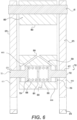
Figures 5 &6 show a third rocker arm configuration. - Reference will now be made in detail to the examples which are illustrated in the accompanying drawings. Wherever possible, the same reference numbers will be used throughout the drawings to refer to the same or like parts. Directional references such as "left" and "right" are for ease of reference to the figures.
- This application provides alternative deactivating rocker arms.
Figures 1A &2A provide alternative rocker arms comprising over-valve mechanical latch assemblies and a pivoting arm arrangement. These rocker arms comprise a midline bisecting the rocker shaft bore. It can be said that a pivot axle, a lost motion spring, and a latch socket are above the midline and a cam interface is below the midline. The latch assembly position can impact forces on the valve actuation. -
Figure 5 provides an alternative deactivating rocker arm. The pivoting arm arrangement comprises a midline bisecting the rocker shaft bore, wherein the pivot axle and the lost motion spring are above the midline and wherein the cam interface and the latch assembly are below the midline. In this configuration there can be provided a three point interaction between the location of the latch assembly, rocker shaft, and pivot axle that can be optimized to change the stress levels on the latch assembly. - In each of the figures, the lost
motion spring pivot axle 40 and thehead figure 2A , the latch socket is between the lostmotion spring 401 and thepivot axle 40. InFigure 1 , the lostmotion spring 400 is between the latch socket and thepivot axle 40. - Returning to
Figures 1A &2A , a deactivating type III (center pivot) rocker arm can be comprised of two members, comprising acam arm 100 and avalve arm mechanical latch assembly cam arm 100 can be configured to pivot about apivot axle 40 and to selectively transfer the motion of a cam to thevalve arm 200 through themechanical latch assembly - The deactivating type III (center pivot) rocker arm 1, 2 can be comprised of two members, comprising a
cam arm 100 and avalve arm mechanical latch assembly valve side arm mechanical latching assembly HLA 70 or mechanical lash adjustment screw that will interface with a valve or valve bridge. The second member can comprise or consist ofcam arm 100. On a first endcam arm end 110, a cam interface area can comprise aroller 10 androller axle 9 for interfacing with a cam on a camshaft. A secondcam arm end 150 of thecam arm 100 can comprise a latch interface for interfacing with a mechanical latch assembly. Apivot axle 40 can connect the first and second members allowing the second member to pivot in lost motion when the latch assembly of the first member is disengaged. - A lost
motion spring motion spring pivot axle 40 when themechanical latch assembly - The mechanical latch assembly, when engaged, translates the motion of the second member to the first member. When disengaged, the mechanical latch assembly is configured to allow the second member to move freely about the
pivot axle 40. The latch assembly can be oriented in multiple ways according toFigures 1A ,2A, 3, 4 , &6 and can be hydraulically or mechanically actuated to switch between an activated configuration (engaged) and a deactivated configuration (disengaged). - In
Figures 2A &6 , a dual latch configuration is shown for the type III deactivating rocker arm. So, the rocker arms 1, 2, 3, can be cylinder deactivation ("CDA") rocker arms for a Type III (center pivot) valvetrain. Whereas a single latch pin (deactivatable latch 501) can have high contact stresses where the latch pin and rocker arm body meet, it can be possible to spread the load over two latch pins (deactivatable latches 60 or 701) to reduce the contact stresses significantly. Locating the two deactivatable latches 60 or 701 to collapse inward near the bearingaxle 9 requires two oil feeds 693, 694 within the rocker arm body 666. The two oil feeds 694, 694 can originate from the rocker shaft bore 663 at acentral location 693 and branch within the rocker arm body. - A deactivating center pivot rocker arm 1, 2 can comprise a
valve arm latch assemblies HLA 70 or mechanical lash adjustment screw configured to interface with a valve or a valve bridge such as through an elephant foot (e-foot) extending from thehead 270 of thevalve arm cam arm 100.Such cam arm 100 can comprise aroller 10 and aroller axle 9 for interfacing with a camshaft. A secondcam arm end 150 can form a latch interface such as a ledge for interfacing with the mechanical latch in the form oflatch assembly 500. The mechanical latch in the form ofmechanical latch assembly 500 selectively mechanically connects the first member to the second member as by the ledge pressing on the protrudingdeactivatable latch 501. In an alternative, secondcam arm end 150 comprisesextensions 160 to mechanically connect the first member to the second member, as byextensions 160 pressing on protruding deactivatable latches 60, 90, or 701. - A
pivot axle 40 can connect the first and second members such that the second member pivots in lost motion when the deactivatable latch mechanism(s) of the first member is disengaged and collapsed into a latch socket in a deactivated configuration. - A lost
motion spring pivot axle 40 when the mechanical latch assembly is disengaged. Themechanical latch assembly pivot axle 40. In some configurations, the pivot axle can be omitted, and the pivot can be freely about the rocker shaft bore 230 as by extending a portion of thecam arm body 110 to wrap around the rocker shaft bore 230. The, the pivot comprises the rocker shaft bore. - The
mechanical latch assemblies - A rocker arm for a type III valvetrain can alternatively comprise a
cam arm 675 comprising a firstcam arm end 673 comprising a cam interface such as aroller 10 on a bearingaxle 9. The bearingaxle 9 can be mounted inbores 679 in the firstcam arm end 673. Aroller bearing 10 can be mounted on a bearingaxle 9 in the bearing axle bores 679 between the first andsecond segments cam arm end 672 can comprise a spring pressing area in the form of a socket for mounting a lostmotion spring 680. Acam arm body 670 can be hollow to comprise first and second segments extending therefrom. The first and second segments can comprise first andsecond latch extension Second latch extension 652 is shown in broken lines inFigure 5 . The first and second segments can comprise the bearing axle bores 679. The first andsecond segments pivot axle 40.Pivot axle 40 can be retained by clips, for example.Latch extensions second latch ports - A
valve arm 660 can comprise a lostmotion spring mount 662 in the form of a second socket in valve side body 666. A 663 rocker shaft bore can be formed so that a branched oil feed extends from the rocker shaft bore 663 to thelatch socket 690. The oil feed comprising a first oil branch formingoil port 693 and a second oil branch formingoil port 694, the oil ports spreading from acentral hole 664. Alatch assembly 700 can be configured in thelatch socket 690. - The
latch socket 690 can comprise acenter wall 691 dividing the latch socket into afirst half 696 and asecond half 695. Thelatch assembly 700 comprises a pair of return springs 704 biased against respective sides of thecenter wall 691. The pair of return springs bias the pair of deactivatable latches 701, 702 apart so that the latches protrude out through first andsecond latch ports oil ports plugs 703 so that first and second plugs surround the first and second deactivatable latches 701, 702. Theplugs 703 can seat in thelatch socket 690 to fluid seal the deactivatable latches and thelatch socket 690. - The rocker arm 2, 3 can comprise a
cam arm cam arm end roller bearing 10. Aspring pressing area cam arm end cam arm body 110 between the firstcam arm end cam arm end pivot axle connection 104 in thecam arm body 110. Thevalve arm valve arm body 284, 666. Thevalve arm body 284, 666 can comprise a rocker shaft bore 230, 663, alatch socket axle mounting area 204 connected to thepivot axle connection 104 by apivot axle 40, and a lostmotion spring mount valve arm neck valve arm body 284, 666. Ahead neck head motion spring motion spring mount spring pressing area latch assembly latch socket latch socket cam arm motion spring cam arm end motion spring cam arm 100 can collapse the lostmotion spring 401. It is possible to collapse or scissor apart the lostmotion spring 680. - At least one
oil port latch socket - In
Figure 3 , thelatch assembly 600 comprise a center spring 65 biasing the pair of deactivatable latches 66 apart. The at least one oil port comprises a pair ofoil ports 260 configured to supply pressurized oil to collapse the pair of deactivatable latches 66 into the latch socket by compressing the center spring 65. Each deactivatable latch 66 can comprise aspring cup 63, aseat portion 61, and alatch pin 64. Pressurized oil togland 233 from rocker shaft bore 230 travels theoil ports 260. The pressure pushes theseat portions 61 to slide in thecavity 256 and collapse the center spring 65. The timing of the deactivation can be controlled by including a controlledoil port 62 out of the latch socket. A size of the controlledoil port 62 controls how fast and in what latch position oil can leak out and depressurize the deactivatable latches 66 to return to their protruding positions, as biased by the center spring 65. The latch socket can comprise aretention wall 2571 and the controlledoil port 62 can be through theretention wall 2571. - The latch socket can comprise a
latch port 259 on afirst side 257 configured so that a first one of the pair of deactivatable latches protrudes out of the valve body. The latch socket can comprise aplug 290 on asecond side 258 configured so that a second one of the pair of deactivatable latches protrudes out of the valve body. - The rocker arms can alternatively comprise a
latch assembly 700 ofFigure 5 &6 , meaning that any of rocker arms 2 & 3 can comprise any one of thedual latch assemblies latch socket 690 can comprise acenter wall 691 dividing thelatch socket 690. Thelatch assembly 700 can comprise a pair of return springs 704 biased against respective sides of thecenter wall 691, the pair of return springs 704 biasing the pair of deactivatable latches 701, 702 apart. The at least one oil port comprises a pair ofoil ports latch socket 690 can comprise afirst latch plug 703 on a first side configured so that a first one 701 of the pair of deactivatable latches protrudes out of the valve body 666. The latch socket can comprise asecond latch plug 703 on a second side configured so that a second one 702 of the pair of deactivatable latches protrudes out of the valve body 666. The valve body can comprise alatch extension 699 to position thelatch assembly 700 below the midline of the rocker arm and adjacent the cam interface. In this configuration there can be provided a three point interaction between the location of thelatch assembly 700, rocker shaft in rocker shaft bore 663, andpivot axle 40 that can be optimized to change the stress levels on thelatch assembly 700. - Turning to
Figure 4 , thelatch assembly 550 comprises an alternative configuration. The latch socket comprises afirst latch port 259 on a first side configured so that a first one of the pair of deactivatable latches 91 protrudes out of the valve body. The latch socket comprises asecond latch port 259 on a second side configured so that a second one of the pair of deactivatable latches 91 protrudes out of the valve body. Amovable member 900 reciprocates in thelatch socket cavity 258 between atop half 257 of the latch socket and abottom half 256. Themovable member 900 comprises amember body 90 and a pair oflatch grooves 92 connected to themember body 90. Amember return spring 99 is biased between a themovable member 900 and thecam arm body 110. Themember return spring 99 can be secured in aspring cup 94 or, like the lostmotion springs member return spring 99 can be secured by another mounting feature, such as a peg, socket, lip, or groove or the like. Themovable member 900 is controllable to align themember body 90 to protrude the pair of deactivatable latches 91 out of the latch socket in the activated configuration andmovable member 900 is controllable to align the pair oflatch grooves 92 to collapse the pair of deactivatable latches 91 into the latch socket. With thelatch grooves 92 aligned with the deactivatable latches 91, when theextensions 160 of the cam arm press down from forces received at the cam interface, theextensions 160 push the balls or other shaped chits into thelatch grooves 92. Controlling the pressure ofspring 99 and oil pressure tooil port 255 controls themovable member 900. Oil pressure to base 93 lifts themovable member 900, while thereturn spring 99 can push themovable member 900 in the absence of oil pressure. Assistance fromcam arm 100 pushing on return spring orspring cup 94 is also possible. - So, it can be said that the rocker arm can comprises an one
oil port 255 extending from the rocker shaft bore 230, 663, the at least oneoil port 255 connected to the latch socket to control themovable member 900 to configure the deactivatable latches 91 in one of the activated configuration or the deactivated configuration. - In
Figure 1A , the rocker arm 1 can comprise acam arm 100 comprising a cam interface at a firstcam arm end 102, a springpressing area 140 at or near a secondcam arm end 150, acam arm body 110 between the firstcam arm end 102 and the secondcam arm end 150, and apivot axle connection 104 in thecam arm body 110. Thevalve arm 200 can comprise avalve arm body 283. Thevalve arm body 283 can comprise a rocker shaft bore 230, a pivotaxle mounting area 204 connected to thepivot axle connection 104 by apivot axle 40, and a lostmotion spring mount 241. The lostmotion spring mount 241 can comprise a socket or the like. Avalve arm neck 280 can extend from thevalve arm body 283. Alatch socket 252 can be in thevalve arm neck 280. Ahead 270 can be connected to theneck 280, thehead 270 configured to interface directly or indirectly with an engine valve. A lostmotion spring 400 can be biased between the lostmotion spring mount 241 toward thespring pressing area 140. Thelatch assembly 500 can be in thelatch socket 252. Thelatch assembly 500 can comprise adeactivatable latch 501 configured to protrude out of thelatch socket 252 in a first configuration to impede motion of thecam arm 100 and configured to collapse in thelatch socket 252 in a second configuration so that the secondcam arm end 150 is movable to collapse the lostmotion spring 400. - The
latch assembly 500 can comprise thedeactivatable latch 501 biased to protrude by areturn spring 505 at a spring mount such asspring cup 504. The deactivatable latch 501 can be held in thelatch socket cavity 252 by a frit or plug 251. Thespring cup 504 can form a seal against awall 250 of thecavity 252 so that thedeactivatable latch 501 can slide against thewall 250 when pressurized oil is supplied byoil port 253. Additional walls can be included to encase thelatch assembly 500 in the latch socket. Alatch pin 503 of deactivatable latch 501 can restrict a ledge on secondcam arm end 150 when it protrudes, and the ledge can pass thelatch pin 503 when the oil pressure collapses thedeactivatable latch 501 in the latch socket. - Other implementations will be apparent to those skilled in the art from consideration of the specification and practice of the examples disclosed herein.
Claims (1)
- A rocker arm, comprising:a cam arm, comprising:a cam interface at a first cam arm end;a spring pressing area at or near a second cam arm end;a cam arm body between the first cam arm end and the second cam arm end; anda pivot axle connection in the cam arm body;a valve arm, comprising:a valve arm body, comprising:a rocker shaft bore;a latch socket;a pivot axle mounting area connected to the pivot axle connection by a pivot axle; anda lost motion spring mount;a valve arm neck extending from the valve arm body; anda head connected to the neck, the head configured to interface directly or indirectly with an engine valve;a lost motion spring biased between the lost motion spring mount and the spring pressing area; anda latch assembly in the latch socket, the latch assembly comprising a pair of deactivatable latches configured to protrude out of the latch socket in an activated configuration to impede travel of the cam arm with respect to the lost motion spring and configured to collapse into the latch socket in a deactivated configuration to enable the second cam arm end to act on the lost motion spring; anda midline bisecting the rocker shaft bore, wherein the pivot axle and the lost motion spring are above the midline and wherein the cam interface and the latch assembly are below the midline.
Applications Claiming Priority (4)
| Application Number | Priority Date | Filing Date | Title |
|---|---|---|---|
| US201862711200P | 2018-07-27 | 2018-07-27 | |
| US201962841175P | 2019-04-30 | 2019-04-30 | |
| PCT/EP2019/025251 WO2020020492A1 (en) | 2018-07-27 | 2019-07-26 | Center pivot latched deactivating rocker arm |
| EP19752648.6A EP3830397B1 (en) | 2018-07-27 | 2019-07-26 | Center pivot latched deactivating rocker arm |
Related Parent Applications (2)
| Application Number | Title | Priority Date | Filing Date |
|---|---|---|---|
| EP19752648.6A Division EP3830397B1 (en) | 2018-07-27 | 2019-07-26 | Center pivot latched deactivating rocker arm |
| EP19752648.6A Division-Into EP3830397B1 (en) | 2018-07-27 | 2019-07-26 | Center pivot latched deactivating rocker arm |
Publications (2)
| Publication Number | Publication Date |
|---|---|
| EP4345263A2 true EP4345263A2 (en) | 2024-04-03 |
| EP4345263A3 EP4345263A3 (en) | 2024-07-03 |
Family
ID=67614543
Family Applications (2)
| Application Number | Title | Priority Date | Filing Date |
|---|---|---|---|
| EP19752648.6A Active EP3830397B1 (en) | 2018-07-27 | 2019-07-26 | Center pivot latched deactivating rocker arm |
| EP24157830.1A Pending EP4345263A3 (en) | 2018-07-27 | 2019-07-26 | Center pivot latched deactivating rocker arm |
Family Applications Before (1)
| Application Number | Title | Priority Date | Filing Date |
|---|---|---|---|
| EP19752648.6A Active EP3830397B1 (en) | 2018-07-27 | 2019-07-26 | Center pivot latched deactivating rocker arm |
Country Status (4)
| Country | Link |
|---|---|
| US (1) | US11313253B2 (en) |
| EP (2) | EP3830397B1 (en) |
| CN (1) | CN112513430B (en) |
| WO (1) | WO2020020492A1 (en) |
Families Citing this family (8)
| Publication number | Priority date | Publication date | Assignee | Title |
|---|---|---|---|---|
| US11566544B2 (en) | 2018-08-09 | 2023-01-31 | Eaton Intelligent Power Limited | Rocker arm assembly with lost motion spring |
| US12146427B2 (en) | 2020-09-30 | 2024-11-19 | STREPARAVA S.p.A. CON SOCIO UNICO | Switchable rocker arm for controlling the lift of a valve bridge or a single valve of valve train group of an internal combustion engine and valve train group comprising at least a such switchable rocker arm |
| DE102021101222A1 (en) | 2021-01-21 | 2022-07-21 | Schaeffler Technologies AG & Co. KG | Assembly for a switchable valve drive of a heavy-duty internal combustion engine |
| DE102021101220A1 (en) | 2021-01-21 | 2022-07-21 | Schaeffler Technologies AG & Co. KG | Carrier module for a switchable valve train of a heavy-duty internal combustion engine |
| CN113153478B (en) * | 2021-04-20 | 2022-11-15 | 一汽解放汽车有限公司 | Engine valve driving mechanism and vehicle |
| DE112023002201T5 (en) | 2022-05-11 | 2025-03-20 | Eaton Intelligent Power Limited | Rocker with switchable rollers for engine valve trains |
| DE112023002826T5 (en) * | 2022-06-29 | 2025-04-10 | Eaton Intelligent Power Limited | Rocker arm system with stopper arrangement on the cam side |
| WO2024094322A1 (en) * | 2022-11-04 | 2024-05-10 | Eaton Intelligent Power Limited | Deactivating roller with torsional spring |
Family Cites Families (21)
| Publication number | Priority date | Publication date | Assignee | Title |
|---|---|---|---|---|
| DE4408808A1 (en) * | 1994-03-16 | 1995-09-21 | Iav Motor Gmbh | IC engine valve gear with alternative cam system |
| US6314928B1 (en) * | 2000-12-06 | 2001-11-13 | Ford Global Technologies, Inc. | Rocker arm assembly |
| US6769387B2 (en) | 2002-10-19 | 2004-08-03 | General Motors Corporation | Compact two-step rocker arm assembly |
| DE10257705A1 (en) | 2002-12-11 | 2004-06-24 | Ina-Schaeffler Kg | Valve lever for valve train of internal combustion engine has outer lever enclosing inner lever with arms and swiveled away from it when decoupled |
| US20050188930A1 (en) * | 2004-02-18 | 2005-09-01 | Best Richard R. | Valve deactivation device |
| KR100667395B1 (en) * | 2005-11-16 | 2007-01-10 | 현대자동차주식회사 | Variable valve lift mechanism of automobile engine |
| US8726863B2 (en) * | 2007-03-16 | 2014-05-20 | Jacobs Vehicle Systems, Inc. | Rocker shaft pedestal incorporating an engine valve actuation system or engine brake |
| US20080271693A1 (en) * | 2007-05-02 | 2008-11-06 | Edelmayer Thomas C | Deactivating rocker arm / mechanical lash adjustment system |
| US20080283003A1 (en) * | 2007-05-16 | 2008-11-20 | Hendriksma Nick J | Two-step roller finger cam follower |
| WO2009151352A1 (en) | 2008-06-13 | 2009-12-17 | Volvo Lastvagnar Ab | Late miller internal combustion engine |
| US8434440B2 (en) * | 2009-06-01 | 2013-05-07 | Schaeffler Technologies AG & Co. KG | Switchable finger lever |
| CN102261283B (en) | 2010-05-27 | 2013-10-09 | 上海尤顺汽车部件有限公司 | A fixed chain engine braking device |
| US9410455B2 (en) * | 2012-12-18 | 2016-08-09 | Jacobs Vehicle Systems, Inc. | Rocker latch for controlling engine valve actuation |
| JP2018519466A (en) * | 2015-06-29 | 2018-07-19 | イートン コーポレーションEaton Corporation | Switching rocker arm for internal exhaust gas recirculation with simple latch control |
| US9926816B2 (en) * | 2015-07-09 | 2018-03-27 | Schaeffler Technologies AG & Co. KG | Switchable rocker arm with pivot joint |
| DE102015015087A1 (en) * | 2015-11-20 | 2017-05-24 | Man Truck & Bus Ag | Variable valve train with a rocker arm |
| US9988947B2 (en) * | 2016-01-11 | 2018-06-05 | Schaeffler Technologies AG & Co. KG | Fast acting switching valve train system for valve deactivation |
| US9976493B2 (en) * | 2016-04-01 | 2018-05-22 | Schaoffler Technologies AG & Co. KG | Switchable rocker arm with reduced coupling assembly loads |
| DE112018005349T5 (en) | 2017-11-10 | 2020-06-18 | Eaton Intelligent Power Limited | DOUBLE LIFT TOGGLE WITH ADDITIONAL MOVEMENT |
| US11566544B2 (en) | 2018-08-09 | 2023-01-31 | Eaton Intelligent Power Limited | Rocker arm assembly with lost motion spring |
| WO2020030298A1 (en) | 2018-08-09 | 2020-02-13 | Eaton Intelligent Power Limited | Deactivating rocker arm having two-stage latch pin |
-
2019
- 2019-07-26 EP EP19752648.6A patent/EP3830397B1/en active Active
- 2019-07-26 EP EP24157830.1A patent/EP4345263A3/en active Pending
- 2019-07-26 US US17/262,819 patent/US11313253B2/en active Active
- 2019-07-26 CN CN201980050047.XA patent/CN112513430B/en active Active
- 2019-07-26 WO PCT/EP2019/025251 patent/WO2020020492A1/en not_active Ceased
Also Published As
| Publication number | Publication date |
|---|---|
| EP4345263A3 (en) | 2024-07-03 |
| CN112513430A (en) | 2021-03-16 |
| US20210310379A1 (en) | 2021-10-07 |
| EP3830397B1 (en) | 2025-12-10 |
| CN112513430B (en) | 2023-01-20 |
| EP3830397A1 (en) | 2021-06-09 |
| WO2020020492A1 (en) | 2020-01-30 |
| US11313253B2 (en) | 2022-04-26 |
Similar Documents
| Publication | Publication Date | Title |
|---|---|---|
| EP3830397B1 (en) | Center pivot latched deactivating rocker arm | |
| US11319840B2 (en) | Deactivating rocker arm having two-stage latch pin | |
| US7546822B2 (en) | Switching finger follower assembly | |
| EP2788595B1 (en) | Rocker arm providing cylinder deactivation | |
| CN115151711B (en) | Rocker assembly, compliant bladder, actuator and support structure | |
| US8960144B2 (en) | Variable valve mechanism of internal combustion engine | |
| EP0275714B1 (en) | Valve operating means in internal combustion engine | |
| US5682847A (en) | Valve actuating device for engine | |
| US10590814B2 (en) | Cylinder deactivation deactivating roller finger follower having improved packaging | |
| US20210324770A1 (en) | Type II Valvetrains to Enable Variable Valve Actuation | |
| US20180320603A1 (en) | Switching rocker arm having cantilevered rollers | |
| EP3959424B1 (en) | Deactivating rocker arm and capsules | |
| US9556762B2 (en) | Variable valve mechanism of internal combustion engine | |
| US10190445B2 (en) | Switchable roller finger follower with integrated leakage path for de-aeration | |
| JP2023546864A (en) | Latch pin assembly and deactivation rocker arm assembly | |
| US12421878B2 (en) | Rocker arm assembly with improved latch pin assembly | |
| US10247062B2 (en) | Variable valve mechanism of internal combustion engine | |
| EP3339584B1 (en) | Engine valve-device | |
| US11828205B2 (en) | Latch assembly and compact rocker arm assembly | |
| JP4535932B2 (en) | Engine valve gear | |
| US12392264B2 (en) | Lifter assembly | |
| JPH0343444B2 (en) | ||
| US12286908B2 (en) | Valvetrain power transfer module with shortened leaf-spring contact | |
| JP2505477B2 (en) | Engine valve gear | |
| JPH01305113A (en) | Valve system device for internal combustion engine |
Legal Events
| Date | Code | Title | Description |
|---|---|---|---|
| PUAI | Public reference made under article 153(3) epc to a published international application that has entered the european phase |
Free format text: ORIGINAL CODE: 0009012 |
|
| STAA | Information on the status of an ep patent application or granted ep patent |
Free format text: STATUS: THE APPLICATION HAS BEEN PUBLISHED |
|
| AC | Divisional application: reference to earlier application |
Ref document number: 3830397 Country of ref document: EP Kind code of ref document: P |
|
| AK | Designated contracting states |
Kind code of ref document: A2 Designated state(s): AL AT BE BG CH CY CZ DE DK EE ES FI FR GB GR HR HU IE IS IT LI LT LU LV MC MK MT NL NO PL PT RO RS SE SI SK SM TR |
|
| REG | Reference to a national code |
Ref country code: DE Ref legal event code: R079 Free format text: PREVIOUS MAIN CLASS: F01L0001460000 Ipc: F01L0001180000 |
|
| PUAL | Search report despatched |
Free format text: ORIGINAL CODE: 0009013 |
|
| AK | Designated contracting states |
Kind code of ref document: A3 Designated state(s): AL AT BE BG CH CY CZ DE DK EE ES FI FR GB GR HR HU IE IS IT LI LT LU LV MC MK MT NL NO PL PT RO RS SE SI SK SM TR |
|
| RIC1 | Information provided on ipc code assigned before grant |
Ipc: F01L 1/46 20060101ALI20240524BHEP Ipc: F01L 13/00 20060101ALI20240524BHEP Ipc: F01L 1/18 20060101AFI20240524BHEP |
|
| STAA | Information on the status of an ep patent application or granted ep patent |
Free format text: STATUS: REQUEST FOR EXAMINATION WAS MADE |
|
| 17P | Request for examination filed |
Effective date: 20241211 |