EP4345204A1 - Warp sizing apparatus - Google Patents
Warp sizing apparatus Download PDFInfo
- Publication number
- EP4345204A1 EP4345204A1 EP23194629.4A EP23194629A EP4345204A1 EP 4345204 A1 EP4345204 A1 EP 4345204A1 EP 23194629 A EP23194629 A EP 23194629A EP 4345204 A1 EP4345204 A1 EP 4345204A1
- Authority
- EP
- European Patent Office
- Prior art keywords
- sizing
- roll
- sizing liquid
- overflowing
- warp
- Prior art date
- Legal status (The legal status is an assumption and is not a legal conclusion. Google has not performed a legal analysis and makes no representation as to the accuracy of the status listed.)
- Pending
Links
Images


Classifications
-
- D—TEXTILES; PAPER
- D06—TREATMENT OF TEXTILES OR THE LIKE; LAUNDERING; FLEXIBLE MATERIALS NOT OTHERWISE PROVIDED FOR
- D06B—TREATING TEXTILE MATERIALS USING LIQUIDS, GASES OR VAPOURS
- D06B1/00—Applying liquids, gases or vapours onto textile materials to effect treatment, e.g. washing, dyeing, bleaching, sizing or impregnating
- D06B1/10—Applying liquids, gases or vapours onto textile materials to effect treatment, e.g. washing, dyeing, bleaching, sizing or impregnating by contact with a member carrying the treating material
- D06B1/14—Applying liquids, gases or vapours onto textile materials to effect treatment, e.g. washing, dyeing, bleaching, sizing or impregnating by contact with a member carrying the treating material with a roller
- D06B1/145—Applying liquids, gases or vapours onto textile materials to effect treatment, e.g. washing, dyeing, bleaching, sizing or impregnating by contact with a member carrying the treating material with a roller the treating material being kept in the trough formed between two or more rollers
-
- D—TEXTILES; PAPER
- D06—TREATMENT OF TEXTILES OR THE LIKE; LAUNDERING; FLEXIBLE MATERIALS NOT OTHERWISE PROVIDED FOR
- D06B—TREATING TEXTILE MATERIALS USING LIQUIDS, GASES OR VAPOURS
- D06B1/00—Applying liquids, gases or vapours onto textile materials to effect treatment, e.g. washing, dyeing, bleaching, sizing or impregnating
- D06B1/10—Applying liquids, gases or vapours onto textile materials to effect treatment, e.g. washing, dyeing, bleaching, sizing or impregnating by contact with a member carrying the treating material
- D06B1/14—Applying liquids, gases or vapours onto textile materials to effect treatment, e.g. washing, dyeing, bleaching, sizing or impregnating by contact with a member carrying the treating material with a roller
- D06B1/148—Applying liquids, gases or vapours onto textile materials to effect treatment, e.g. washing, dyeing, bleaching, sizing or impregnating by contact with a member carrying the treating material with a roller the treating material being supplied to the roller by spraying or pouring
Definitions
- the present invention relates to a warp sizing apparatus including a sizing tank in which a sizing liquid is stored, a first roll on which a warp sheet is wound, a second roll provided on a rear side with respect to the first roll so as to be circumscribed around the first roll on an upstream side in a traveling direction of the warp sheet, and a sizing liquid supply device configured to supply the sizing liquid so as to form a sizing liquid pool in a wedge-shaped region formed above a circumscribed position of the first roll and the second roll.
- Patent Literature 1 discloses a warp sizing apparatus for performing sizing on a warp sheet.
- the warp sizing apparatus disclosed in Patent Literature 1 includes a drive roll (first roll) on which a warp sheet is wound, a first support roll (second roll) circumscribed around the first roll so as to position a path of the warp sheet therebetween.
- the warp sizing apparatus includes a sizing liquid supply device that supplies the sizing liquid so as to form a sizing liquid pool in a wedge-shaped region formed above a circumscribed position of the first roll and the second roll.
- the sizing liquid is supplied from the sizing liquid supply device to the wedge-shaped region and the warp sheet passes between the first roll and the second roll (passes through the sizing liquid pool), so that sizing is performed on the warp sheet while the extra sizing liquid is squeezed from the warp sheet.
- Patent Literature 1 JP2013-002029A
- the warp sizing apparatus of Patent Literature 1 in the case of the configuration where the sizing liquid is supplied from the sizing liquid supply device to the wedge-shaped region, the sizing liquid flows down from the sizing liquid pool formed in the wedge-shaped region to a side of the roll. For this reason, the warp sizing apparatus needs to have a configuration for receiving the sizing liquid (overflowing sizing liquid) flowing down from the sizing liquid pool.
- the warp sizing apparatus is provided with a configuration for receiving the overflowing sizing liquid.
- the present invention is to provide a warp sizing apparatus having a configuration for receiving the overflowing sizing liquid.
- the present invention has the warp sizing apparatus as described above, as a preamble, and includes a receiving part configured to receive an overflowing sizing liquid overflowing from the sizing liquid pool, and the receiving part has a receiving surface that is at least present within a range including a presence range of the sizing liquid pool with respect to a front-rear direction and is inclined in the front-rear direction, and a restriction surface extending upward from an upper end of the receiving surface with respect to the front-rear direction and configured to block flow of the overflowing sizing liquid flowing toward the upper end side on the receiving surface.
- the warp sizing apparatus of the present invention includes the receiving part for receiving the overflowing sizing liquid overflowing from the sizing liquid pool, so the overflowing sizing liquid is received on the receiving part.
- the receiving part is configured so that the overflowing sizing liquid is received by the receiving surface that is at least present within the range including the presence range of the sizing liquid pool with respect to the front-rear direction and is inclined in the front-rear direction. Therefore, according to the configuration, since the overflowing sizing liquid received on the receiving surface flows along an inclination on the receiving surface, the received overflowing sizing liquid can be appropriately guided toward a configuration for collecting the sizing liquid, or the like.
- the receiving part has the restriction surface continuing to the upper end of the receiving surface, extending upward and configured to block flow of the overflowing sizing liquid flowing toward the upper end side on the receiving surface.
- the overflowing sizing liquid received on the receiving surface as described above will take a form of flowing to spread in all directions from a drop position on the receiving surface due to collision with the receiving surface. That is, the overflowing sizing liquid received on the receiving surface is in a state of flowing not only in a descending direction (toward a lower end side) but also in an ascending direction (toward an upper end side) on the receiving surface inclined in the front-rear direction. Note that since the flow of the liquid flowing in the ascending direction on the inclined surface is in a form that opposes the inclination, the liquid stops ascending at a position that has ascended to some extent, and is folded back and flows toward the lower end side from the position.
- the sizing liquid temporarily stays at the fold-back position. Since the sizing liquid stays as such and therefore tends to harden, a lump of the sizing liquid is formed in the vicinity of the fold-back position on the receiving surface and adheres to the receiving surface. For this reason, when the operator cleans the receiving part, the operator should perform an operation of removing the lump of the sizing liquid, which increases the burden of the cleaning operation.
- the receiving part of the present invention has the restriction surface provided to block the overflowing sizing liquid flowing toward the upper end side on the receiving surface.
- the term 'block' means colliding with the middle of the flow of the overflowing sizing liquid flowing toward the upper end side, thereby stopping the flow toward the upper end side. Therefore, the restriction surface is provided at a position on a further lower end side than the fold-back position with respect to the front-rear direction. Note that the overflowing sizing liquid blocked by the restriction surface naturally reverses its flow direction (flows toward the lower end) after colliding with the restriction surface.
- the overflowing sizing liquid flowing toward the upper end side on the receiving surface is blocked in the middle of the flow by the restriction surface, and then flows toward the lower end side. This prevents the occurrence of the situation in which the sizing liquid tends to harden along with the staying of the sizing liquid (at the fold-back position) as described above. Therefore, since the sizing liquid is prevented from hardening on the receiving surface as much as possible, the burden on the operator when cleaning the receiving part can be reduced.
- FIGS. 1 to 4 one embodiment of a warp sizing apparatus to which the present invention is applied will be described with reference to FIGS. 1 to 4 .
- a warp sizing apparatus 1 includes a sizing tank 3 in which a sizing liquid S is stored, a sizing roll 11 on which a warp sheet T is wound and which is immersed in the sizing liquid S, and a first squeeze roll 13 and a second squeeze roll 15 circumscribed around the sizing roll 11.
- the sizing roll 11, the first squeeze roll 13, and the second squeeze roll 15 are rolls having substantially the same dimensions in axis line directions thereof.
- the warp sizing apparatus 1 includes a sizing liquid supply device 20 that supplies, from above, the sizing liquid S to a circumscribed position of the sizing roll 11 and the first squeeze roll 13. Note that, in the present embodiment, the sizing roll 11 corresponds to the first roll referred to in the present invention, and the first squeeze roll 13 corresponds to the second roll.
- the sizing roll 11 is a roll on which the warp sheet T is wound.
- the sizing roll 11 is rotatably supported with respect to a frame (not shown) of the warp sizing apparatus 1 by support shafts 12 and 12 attached to both ends of the sizing roll.
- the sizing roll 11 is provided such that a lower part thereof is in a state of being immersed in the sizing liquid S stored in the sizing tank 3.
- the warp sizing apparatus 1 includes a drive mechanism (not shown) that rotationally drives the sizing roll 11. Thereby, the sizing roll 11 is rotationally driven positively in conformity with advancing of the warp sheet T.
- the warp sheet T is guided in the form of being wound onto the sizing roll 11, and is immersed in the sizing liquid S and is impregnated with the sizing liquid S during such guiding.
- the second squeeze roll 15 is a roll for squeezing the sizing liquid S impregnated in the warp sheet T, and is provided in arrangement of being positioned on a front side with respect to the sizing roll 11.
- the second squeeze roll 15 is rotatably supported with respect to the frame by support shafts 16 and 16 attached to both ends of the second squeeze roll, in a direction in which the axis line direction of the second squeeze roll is made to coincide with the axis line direction of the sizing roll 11 (width direction of the warp sizing apparatus 1).
- the second squeeze roll 15 is supported with respect to the frame via a pressing mechanism (not shown), and is provided to be circumscribed in a state of being pressed against the sizing roll 11. Therefore, the second squeeze roll 15 is adapted to rotate as the sizing roll 11 is rotationally driven as described above.
- the warp sheet T wound on the sizing roll 11 as described above passes between the sizing roll 11 and the second squeeze roll 15 circumscribed as described above, and is then pulled out toward an outside.
- the extra sizing liquid S is squeezed from the warp sheet T impregnated with the sizing liquid S as described above.
- the first squeeze roll 13 is provided in arrangement of being positioned on a rear side with respect to the sizing roll 11.
- the first squeeze roll 13 is also rotatably supported with respect to the frame by support shafts 14 and 14 attached to both ends thereof, in a direction in which the axis line direction of the first squeeze roll is made to coincide with the width direction.
- the first squeeze roll 13 is also rotatably supported with respect to the frame via the pressing mechanism and is circumscribed in a state of being pressed against the sizing roll 11, like the second squeeze roll 15. Therefore, the first squeeze roll 13 is also adapted to rotate as the sizing roll 11 is rotationally driven.
- the sizing tank 3 is a housing with an open upper surface and is formed by a bottom plate 4, front and rear end walls 5 and 6, and left and right side walls 7 and 7.
- the sizing tank 3 is provided so that the end wall 5 on the front side is located slightly in front of the circumscribed position of the sizing roll 11 and the second squeeze roll 15 with respect to the front-rear direction of the warp sizing apparatus 1.
- the sizing tank 3 has such a size in the front-rear direction that the end wall 6 on the rear side is located slightly behind the circumscribed position of the sizing roll 11 and the first squeeze roll 13.
- the first squeeze roll 13 is circumscribed around the sizing roll 11 as described above, so that a wedge-shaped region, which is a wedge-shaped gap, is formed between the sizing roll 11 and the first squeeze roll 13 (above the circumscribed position).
- a sizing liquid supply device 20 for supplying the sizing liquid S toward the wedge-shaped region is provided above the wedge-shaped region.
- the sizing liquid supply device 20 is configured to include a sizing liquid supply pipe 22 extending along the axis line direction of the sizing roll 11 and a nozzle 24 attached to the sizing liquid supply pipe 22.
- a supply pipe 26 is connected to one end portion of the sizing liquid supply pipe 22 (which is not shown), and the sizing liquid S is supplied from a supply source 28 via the supply pipe 26.
- the sizing liquid S is supplied to the wedge-shaped region via the sizing liquid supply device 20, so that a sizing liquid pool 18 in which the sizing liquid S is retained is formed in the wedge-shaped region.
- the sizing liquid pool 18 is located ahead of the end wall 6 on the rear side of the sizing tank 3 with respect to the front-rear direction.
- the warp sheet T is guided in the form of being wound onto the first squeeze roll 13, passes between the sizing roll 11 and the first squeeze roll 13 circumscribed as described above, and is then wound on the sizing roll 11 as described above. Then, the warp sheet T passes through the sizing liquid pool 18 formed between both the rolls, so that the sizing liquid S is impregnated in the warp sheet T.
- the warp sheet T impregnated with the sizing liquid S passes between the sizing roll 11 and the first squeeze roll 13, the extra sizing liquid S is squeezed from the warp sheet T.
- the warp sizing apparatus has a receiving part for receiving the sizing liquid (overflowing sizing liquid) overflowing from the sizing liquid pool.
- the receiving part is configured so that the overflowing sizing liquid is received by a receiving surface that is at least present within a range including a presence range of the sizing liquid pool with respect to the front-rear direction and is inclined in the front-rear direction.
- the receiving part has a restriction surface that continues to an upper end of the receiving surface, extends upward and blocks flow of the overflowing sizing liquid flowing toward the upper end side on the receiving surface.
- the warp sizing apparatus 1 includes a pair of guiding paths 30 and 30 provided on both sides of the sizing tank 3, and a collection path 40 which is provided in front of the sizing tank 3 and to which both guiding paths 30 and 30 continue.
- each guiding path 30 has a guiding part 32 having a plate shape.
- Each guiding part 32 is provided to be in contact with the side wall 7 of the sizing tank 3 on each of both sides of the sizing tank 3.
- each guiding part 32 has such a size that it is present between the front and rear end walls 5 and 6 of the sizing tank 3 with respect to the front-rear direction. More specifically, each guiding part 32 is provided such that its front end is located substantially at the same position as the end wall 5 on the front side of the sizing tank 3 and its rear end is located substantially at the same position as the end wall 6 on the rear side of the sizing tank 3. Therefore, a presence range of each guiding part 32 includes a presence range of the sizing liquid pool 18 in the front-rear direction. In addition, each guiding part 32 is provided to be inclined downward from the rear toward the front.
- each guiding path 30 has a restriction portion 34 extending upward from a rear end (upper end with respect to the vertical direction) of the guiding part 32. Note that, as described above, since the position of the rear end of the guiding part 32 of each guiding path 30 is substantially the same as that of the end wall 6 on the rear side of the sizing tank 3 in the front-rear direction, naturally, the restriction portion 34 is also located behind the sizing liquid pool 18 in the front-rear direction.
- the collection path 40 is configured by a rectangular plate-shaped bottom wall 42 and both vertical walls 44 and 44, and is formed so that its cross section forms a U-shaped gutter shape.
- a size of the collection path 40 in a longitudinal direction (long side direction of the bottom wall 42 and the vertical wall 44) is larger than a size of the sizing tank 3 in the width direction.
- the collection path 40 is provided in such a form that its longitudinal direction is made to coincide with the width direction at a position in front of the sizing tank 3 and its center is made to coincide with the center of the sizing tank 3 with respect to the width direction.
- a presence range of the collection path 40 in the width direction includes the presence range of the sizing tank 3.
- positions of both end edges of the collection path 40 are substantially the same as the outer side edges of the guiding paths 30 with respect to the width direction.
- the collection path 40 is provided to be in contact with the end wall 5 on the front side of the sizing tank 3 at an upper edge of the vertical wall 44 on the rear side and to be continuous with the front end of each guiding path 30 at the upper edge.
- the collection path 40 and both the guiding paths 30 and 30 are integrally formed.
- the collection path 40 is a flow path for guiding the collected sizing liquid S to the collection device 70. Therefore, the bottom wall 42 of the collection path 40 is formed in a slightly bent shape at the center so as to be inclined downward from both end edges toward the center with respect to the longitudinal direction (width direction). In addition, a through-hole 42a penetrating through the bottom wall 42 in the vertical direction is formed at a position of the center of the bottom wall 42 in the longitudinal direction. Further, the through-hole 42a is connected to the collection device 70 for the sizing liquid S provided outside via a pipe or the like (not shown).
- the warp sizing apparatus 1 has a plate-shaped rear-side wall part 50 that receives the sizing liquid that scatters to the rear of the sizing tank 3 along with the rotation of the first squeeze roll 13.
- the rear-side wall part 50 is formed in a shape of extending rearward from the end wall 6 on the rear side of the sizing tank 3 and extending upward from a position behind the first squeeze roll 13.
- the rear-side wall part 50 has substantially the same size as the collection path 40 with respect to the width direction.
- the rear-side wall part 50 is provided in the form of being continuous with both the guiding paths 30 and 30 (upper edges of the restriction portions 34 and 34) located on both sides of the sizing tank 3.
- the rear-side wall part 50 is formed integrally with both the guiding paths 30 and 30.
- the warp sizing apparatus 1 has a front-side wall part 52 continuing to the collection path 40 and extending upward from a position in front of the second squeeze roll 15, on a front side of the collection path 40.
- a size of the front-side wall part 52 in the width direction is also substantially the same as the size of the collection path 40 (rear-side wall part 50) in the width direction.
- the warp sizing apparatus 1 has a space, which is defined by the rear-side wall part 50 and the front-side wall part 52 with respect to the front-rear direction, and in which portions of the sizing roll 11, the first squeeze roll 13, and the second squeeze roll 15 are present.
- the warp sizing apparatus 1 includes a pair of side frames 60 and 60 provided in the form of closing both sides of the space. Therefore, in the warp sizing apparatus 1, each guiding path 30 is located between the sizing tank 3 (side wall 7) and the side frame 60 on each of both sides in the width direction, and in the presence range of the guiding path 30 in the front-rear direction, the guiding path 30, the side wall 7, and the side frame 60 form a flow path on which the sizing liquid S flows.
- the warp sizing apparatus 1 of the present embodiment configured as described above, during an operation of the warp sizing apparatus 1 (during warp sizing), as the sizing liquid S is supplied to the wedge-shaped region by the sizing liquid supply device 20, the sizing liquid S overflows from the sizing liquid pool 18 and, as described above, flows down to a side of the roll, as the overflowing sizing liquid.
- the guiding paths 30 guiding parts 32
- the overflowing sizing liquid is received by the guiding parts 32.
- each guiding path 30 for receiving the overflowing sizing liquid corresponds to the receiving part of the present invention
- the upper surface of the guiding part 32 of each guiding path 30 for receiving the overflowing sizing liquid corresponds to the receiving surface.
- the received overflowing sizing liquid flows forward on the guiding part 32. Note that, as described above, since the flow path on which the sizing liquid S flows is formed by the guiding path 30, the side wall 7 and the side frame 60, the flow in the width direction of the overflowing sizing liquid received on the guiding part 32 is blocked by the side wall 7 and the side frame 60.
- the collection path 40 is provided in the form of continuing to the front end of the guiding path 30 (guiding part 32), the overflowing sizing liquid flowing forward on the guiding part 32 flows down onto the bottom wall 42 of the collection path 40. Then, the overflowing sizing liquid that has flowed down onto the bottom wall 42 flows toward the through-hole 42a and is collected 70 via the pipe or the like by the collection device.
- the sizing liquid that is scattered to the rear of the sizing tank 3 along with the rotation of the first squeeze roll 13 is received by the rear-side wall part 50, and the sizing liquid received by the rear-side wall part 50 is also sent to the collection path 40 via both the guiding paths 30.
- the overflowing sizing liquid received by the guiding part 32 of each guiding path 30 flows from the drop position on the guiding part 32 even toward the upper end side of the guiding part 32 due to collision with the guiding part 32.
- the guiding path 30 has the restriction portion 34 extending upward from the upper end of the guiding part 32.
- the restriction portion 34 is located substantially at the same position as the end wall 6 on the rear side of the sizing tank 3 with respect to the front-rear direction, and the position is near the drop position of the overflowing sizing solution on the guiding part 32.
- the overflowing sizing liquid flowing toward the upper end side collides with the restriction portion 34 and is blocked before the flow toward the upper end side is stopped by the restriction portion 34. Then, after colliding with the restriction portion 34, the overflowing sizing liquid reverses the flow direction, and flows toward the lower end side of the guiding part 32. Thereby, since the overflowing sizing liquid is prevented from hardening on the guiding path 30 (receiving part) as much as possible, the burden on the operator when cleaning the receiving part can be reduced.
- the surface of the restriction portion 34 of each guiding path 30 for blocking the flow of the overflowing sizing liquid corresponds to the restriction surface of the present invention.
- the warp sizing apparatus it is common that a new sizing liquid is always or periodically supplied to the sizing tank 3.
- the guiding path 30 and the collection path 40 are provided to be in contact with the sizing tank 3 at the side and at the front of the sizing tank 3.
- the sizing liquid overflowing from the sizing tank 3 as described above is received on the guiding path 30 and the collection path 40, and flows toward the through-hole 42a of the collection path 40 and is collected, similarly to the overflowing sizing liquid described above.
- the guiding path 30 of the present embodiment also serves as a part of the configuration for collecting the sizing liquid overflowing from the sizing tank 3.
- the warp sizing apparatus 1 of the above embodiment is configured such that the sizing roll 11 is immersed in the sizing liquid in the sizing tank 3 and the first and second squeeze rolls 13 and 15 are each circumscribed around the sizing roll 11 so as to sandwich the path of the warp sheet T therebetween.
- the warp sizing apparatus that is the preamble of the present invention is not limited to such a configuration.
- the warp sizing apparatus may also be configured such that the second squeeze roll is also immersed in the sizing liquid in the sizing tank, in addition to the sizing roll.
- the sizing tank is dimensioned to include the sizing roll and the second squeeze roll in the front-rear direction.
- the warp sizing apparatus may also be configured such that only the second squeeze roll is immersed in the sizing liquid S in the sizing tank, as in Patent Literature 1 described above.
- the present invention is not limited to the above embodiment, and can be variously changed without departing from the gist of the present invention.
Landscapes
- Engineering & Computer Science (AREA)
- Textile Engineering (AREA)
- Treatment Of Fiber Materials (AREA)
- Treatments For Attaching Organic Compounds To Fibrous Goods (AREA)
Abstract
Description
- The present invention relates to a warp sizing apparatus including a sizing tank in which a sizing liquid is stored, a first roll on which a warp sheet is wound, a second roll provided on a rear side with respect to the first roll so as to be circumscribed around the first roll on an upstream side in a traveling direction of the warp sheet, and a sizing liquid supply device configured to supply the sizing liquid so as to form a sizing liquid pool in a wedge-shaped region formed above a circumscribed position of the first roll and the second roll.
- For example,
Patent Literature 1 discloses a warp sizing apparatus for performing sizing on a warp sheet. The warp sizing apparatus disclosed inPatent Literature 1 includes a drive roll (first roll) on which a warp sheet is wound, a first support roll (second roll) circumscribed around the first roll so as to position a path of the warp sheet therebetween. In addition, the warp sizing apparatus includes a sizing liquid supply device that supplies the sizing liquid so as to form a sizing liquid pool in a wedge-shaped region formed above a circumscribed position of the first roll and the second roll. In the warp sizing apparatus, the sizing liquid is supplied from the sizing liquid supply device to the wedge-shaped region and the warp sheet passes between the first roll and the second roll (passes through the sizing liquid pool), so that sizing is performed on the warp sheet while the extra sizing liquid is squeezed from the warp sheet. - Patent Literature 1:
JP2013-002029A - As in the warp sizing apparatus of
Patent Literature 1, in the case of the configuration where the sizing liquid is supplied from the sizing liquid supply device to the wedge-shaped region, the sizing liquid flows down from the sizing liquid pool formed in the wedge-shaped region to a side of the roll. For this reason, the warp sizing apparatus needs to have a configuration for receiving the sizing liquid (overflowing sizing liquid) flowing down from the sizing liquid pool. However, there is no literature in the related art disclosing that the warp sizing apparatus is provided with a configuration for receiving the overflowing sizing liquid. - Therefore, the present invention is to provide a warp sizing apparatus having a configuration for receiving the overflowing sizing liquid.
- In order to achieve the above object, the present invention has the warp sizing apparatus as described above, as a preamble, and includes a receiving part configured to receive an overflowing sizing liquid overflowing from the sizing liquid pool, and the receiving part has a receiving surface that is at least present within a range including a presence range of the sizing liquid pool with respect to a front-rear direction and is inclined in the front-rear direction, and a restriction surface extending upward from an upper end of the receiving surface with respect to the front-rear direction and configured to block flow of the overflowing sizing liquid flowing toward the upper end side on the receiving surface.
- As described above, the warp sizing apparatus of the present invention includes the receiving part for receiving the overflowing sizing liquid overflowing from the sizing liquid pool, so the overflowing sizing liquid is received on the receiving part. The receiving part is configured so that the overflowing sizing liquid is received by the receiving surface that is at least present within the range including the presence range of the sizing liquid pool with respect to the front-rear direction and is inclined in the front-rear direction. Therefore, according to the configuration, since the overflowing sizing liquid received on the receiving surface flows along an inclination on the receiving surface, the received overflowing sizing liquid can be appropriately guided toward a configuration for collecting the sizing liquid, or the like.
- In addition, the receiving part has the restriction surface continuing to the upper end of the receiving surface, extending upward and configured to block flow of the overflowing sizing liquid flowing toward the upper end side on the receiving surface. According to this configuration, since the overflowing sizing liquid received on the receiving surface is prevented from hardening on the receiving surface as much as possible, a burden on an operator when cleaning the receiving part can be reduced.
- Specifically, the overflowing sizing liquid received on the receiving surface as described above will take a form of flowing to spread in all directions from a drop position on the receiving surface due to collision with the receiving surface. That is, the overflowing sizing liquid received on the receiving surface is in a state of flowing not only in a descending direction (toward a lower end side) but also in an ascending direction (toward an upper end side) on the receiving surface inclined in the front-rear direction. Note that since the flow of the liquid flowing in the ascending direction on the inclined surface is in a form that opposes the inclination, the liquid stops ascending at a position that has ascended to some extent, and is folded back and flows toward the lower end side from the position.
- In addition, if the receiving surface is formed to extend in a planar shape upstream of the inclination from the fold-back position at which the overflowing sizing liquid flowing in the ascending direction is folded back, the sizing liquid temporarily stays at the fold-back position. Since the sizing liquid stays as such and therefore tends to harden, a lump of the sizing liquid is formed in the vicinity of the fold-back position on the receiving surface and adheres to the receiving surface. For this reason, when the operator cleans the receiving part, the operator should perform an operation of removing the lump of the sizing liquid, which increases the burden of the cleaning operation.
- On the other hand, the receiving part of the present invention has the restriction surface provided to block the overflowing sizing liquid flowing toward the upper end side on the receiving surface. As used herein, the term 'block' means colliding with the middle of the flow of the overflowing sizing liquid flowing toward the upper end side, thereby stopping the flow toward the upper end side. Therefore, the restriction surface is provided at a position on a further lower end side than the fold-back position with respect to the front-rear direction. Note that the overflowing sizing liquid blocked by the restriction surface naturally reverses its flow direction (flows toward the lower end) after colliding with the restriction surface.
- According to the configuration, the overflowing sizing liquid flowing toward the upper end side on the receiving surface is blocked in the middle of the flow by the restriction surface, and then flows toward the lower end side. This prevents the occurrence of the situation in which the sizing liquid tends to harden along with the staying of the sizing liquid (at the fold-back position) as described above. Therefore, since the sizing liquid is prevented from hardening on the receiving surface as much as possible, the burden on the operator when cleaning the receiving part can be reduced.
-
-
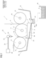
FIG. 1 is a side view of a warp sizing apparatus according to one embodiment of the present invention. -
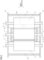
FIG. 2 is a plan view of the warp sizing apparatus according to one embodiment of the present invention. -
FIG. 3 is an enlarged side view of a main part of the warp sizing apparatus according to one embodiment of the present invention. -
FIG. 4 is a perspective view of the warp sizing apparatus according to one embodiment of the present invention. - Hereinafter, one embodiment of a warp sizing apparatus to which the present invention is applied will be described with reference to
FIGS. 1 to 4 . - A
warp sizing apparatus 1 includes asizing tank 3 in which a sizing liquid S is stored, asizing roll 11 on which a warp sheet T is wound and which is immersed in the sizing liquid S, and afirst squeeze roll 13 and asecond squeeze roll 15 circumscribed around thesizing roll 11. However, thesizing roll 11, thefirst squeeze roll 13, and thesecond squeeze roll 15 are rolls having substantially the same dimensions in axis line directions thereof. In addition, thewarp sizing apparatus 1 includes a sizingliquid supply device 20 that supplies, from above, the sizing liquid S to a circumscribed position of thesizing roll 11 and thefirst squeeze roll 13. Note that, in the present embodiment, thesizing roll 11 corresponds to the first roll referred to in the present invention, and thefirst squeeze roll 13 corresponds to the second roll. - The
sizing roll 11 is a roll on which the warp sheet T is wound. Thesizing roll 11 is rotatably supported with respect to a frame (not shown) of thewarp sizing apparatus 1 bysupport shafts sizing roll 11 is provided such that a lower part thereof is in a state of being immersed in the sizing liquid S stored in thesizing tank 3. - Note that the
warp sizing apparatus 1 includes a drive mechanism (not shown) that rotationally drives thesizing roll 11. Thereby, thesizing roll 11 is rotationally driven positively in conformity with advancing of the warp sheet T. The warp sheet T is guided in the form of being wound onto thesizing roll 11, and is immersed in the sizing liquid S and is impregnated with the sizing liquid S during such guiding. - The
second squeeze roll 15 is a roll for squeezing the sizing liquid S impregnated in the warp sheet T, and is provided in arrangement of being positioned on a front side with respect to thesizing roll 11. In addition, thesecond squeeze roll 15 is rotatably supported with respect to the frame bysupport shafts second squeeze roll 15 is supported with respect to the frame via a pressing mechanism (not shown), and is provided to be circumscribed in a state of being pressed against thesizing roll 11. Therefore, thesecond squeeze roll 15 is adapted to rotate as thesizing roll 11 is rotationally driven as described above. - The warp sheet T wound on the
sizing roll 11 as described above passes between thesizing roll 11 and thesecond squeeze roll 15 circumscribed as described above, and is then pulled out toward an outside. In addition, when passing between thesizing roll 11 and thesecond squeeze roll 15 as such, the extra sizing liquid S is squeezed from the warp sheet T impregnated with the sizing liquid S as described above. - The
first squeeze roll 13 is provided in arrangement of being positioned on a rear side with respect to thesizing roll 11. Thefirst squeeze roll 13 is also rotatably supported with respect to the frame bysupport shafts first squeeze roll 13 is also rotatably supported with respect to the frame via the pressing mechanism and is circumscribed in a state of being pressed against thesizing roll 11, like thesecond squeeze roll 15. Therefore, thefirst squeeze roll 13 is also adapted to rotate as thesizing roll 11 is rotationally driven. - Note that the
sizing tank 3 is a housing with an open upper surface and is formed by abottom plate 4, front andrear end walls sizing tank 3 is provided so that theend wall 5 on the front side is located slightly in front of the circumscribed position of thesizing roll 11 and thesecond squeeze roll 15 with respect to the front-rear direction of thewarp sizing apparatus 1. Further, thesizing tank 3 has such a size in the front-rear direction that theend wall 6 on the rear side is located slightly behind the circumscribed position of thesizing roll 11 and thefirst squeeze roll 13. - Further, in the
warp sizing apparatus 1, thefirst squeeze roll 13 is circumscribed around thesizing roll 11 as described above, so that a wedge-shaped region, which is a wedge-shaped gap, is formed between thesizing roll 11 and the first squeeze roll 13 (above the circumscribed position). In addition, a sizingliquid supply device 20 for supplying the sizing liquid S toward the wedge-shaped region is provided above the wedge-shaped region. - The sizing
liquid supply device 20 is configured to include a sizingliquid supply pipe 22 extending along the axis line direction of the sizingroll 11 and anozzle 24 attached to the sizingliquid supply pipe 22. In addition, asupply pipe 26 is connected to one end portion of the sizing liquid supply pipe 22 (which is not shown), and the sizing liquid S is supplied from asupply source 28 via thesupply pipe 26. Thereby, in thewarp sizing apparatus 1, the sizing liquid S is supplied to the wedge-shaped region via the sizingliquid supply device 20, so that a sizingliquid pool 18 in which the sizing liquid S is retained is formed in the wedge-shaped region. Note that the sizingliquid pool 18 is located ahead of theend wall 6 on the rear side of thesizing tank 3 with respect to the front-rear direction. - In addition, the warp sheet T is guided in the form of being wound onto the
first squeeze roll 13, passes between the sizingroll 11 and thefirst squeeze roll 13 circumscribed as described above, and is then wound on the sizingroll 11 as described above. Then, the warp sheet T passes through the sizingliquid pool 18 formed between both the rolls, so that the sizing liquid S is impregnated in the warp sheet T. When the warp sheet T impregnated with the sizing liquid S passes between the sizingroll 11 and thefirst squeeze roll 13, the extra sizing liquid S is squeezed from the warp sheet T. - In the
warp sizing apparatus 1 as described above, in the present invention, the warp sizing apparatus has a receiving part for receiving the sizing liquid (overflowing sizing liquid) overflowing from the sizing liquid pool. The receiving part is configured so that the overflowing sizing liquid is received by a receiving surface that is at least present within a range including a presence range of the sizing liquid pool with respect to the front-rear direction and is inclined in the front-rear direction. In addition, the receiving part has a restriction surface that continues to an upper end of the receiving surface, extends upward and blocks flow of the overflowing sizing liquid flowing toward the upper end side on the receiving surface. Hereinafter, one embodiment of such a warp sizing apparatus of the present invention will be described in detail. - The
warp sizing apparatus 1 includes a pair of guidingpaths sizing tank 3, and acollection path 40 which is provided in front of thesizing tank 3 and to which both guidingpaths - First, each guiding
path 30 has a guidingpart 32 having a plate shape. Each guidingpart 32 is provided to be in contact with the side wall 7 of thesizing tank 3 on each of both sides of thesizing tank 3. In addition, each guidingpart 32 has such a size that it is present between the front andrear end walls sizing tank 3 with respect to the front-rear direction. More specifically, each guidingpart 32 is provided such that its front end is located substantially at the same position as theend wall 5 on the front side of thesizing tank 3 and its rear end is located substantially at the same position as theend wall 6 on the rear side of thesizing tank 3. Therefore, a presence range of each guidingpart 32 includes a presence range of the sizingliquid pool 18 in the front-rear direction. In addition, each guidingpart 32 is provided to be inclined downward from the rear toward the front. - Further, each guiding
path 30 has arestriction portion 34 extending upward from a rear end (upper end with respect to the vertical direction) of the guidingpart 32. Note that, as described above, since the position of the rear end of the guidingpart 32 of each guidingpath 30 is substantially the same as that of theend wall 6 on the rear side of thesizing tank 3 in the front-rear direction, naturally, therestriction portion 34 is also located behind the sizingliquid pool 18 in the front-rear direction. - The
collection path 40 is configured by a rectangular plate-shapedbottom wall 42 and bothvertical walls collection path 40 in a longitudinal direction (long side direction of thebottom wall 42 and the vertical wall 44) is larger than a size of thesizing tank 3 in the width direction. Thecollection path 40 is provided in such a form that its longitudinal direction is made to coincide with the width direction at a position in front of thesizing tank 3 and its center is made to coincide with the center of thesizing tank 3 with respect to the width direction. Thereby, a presence range of thecollection path 40 in the width direction includes the presence range of thesizing tank 3. In addition, positions of both end edges of thecollection path 40 are substantially the same as the outer side edges of the guidingpaths 30 with respect to the width direction. - Regarding the arrangement in the front-rear direction, the
collection path 40 is provided to be in contact with theend wall 5 on the front side of thesizing tank 3 at an upper edge of thevertical wall 44 on the rear side and to be continuous with the front end of each guidingpath 30 at the upper edge. For reference, in the shown example, thecollection path 40 and both the guidingpaths - Note that the
collection path 40 is a flow path for guiding the collected sizing liquid S to thecollection device 70. Therefore, thebottom wall 42 of thecollection path 40 is formed in a slightly bent shape at the center so as to be inclined downward from both end edges toward the center with respect to the longitudinal direction (width direction). In addition, a through-hole 42a penetrating through thebottom wall 42 in the vertical direction is formed at a position of the center of thebottom wall 42 in the longitudinal direction. Further, the through-hole 42a is connected to thecollection device 70 for the sizing liquid S provided outside via a pipe or the like (not shown). - Further, in the shown example, the
warp sizing apparatus 1 has a plate-shaped rear-side wall part 50 that receives the sizing liquid that scatters to the rear of thesizing tank 3 along with the rotation of thefirst squeeze roll 13. The rear-side wall part 50 is formed in a shape of extending rearward from theend wall 6 on the rear side of thesizing tank 3 and extending upward from a position behind thefirst squeeze roll 13. In addition, the rear-side wall part 50 has substantially the same size as thecollection path 40 with respect to the width direction. Further, the rear-side wall part 50 is provided in the form of being continuous with both the guidingpaths 30 and 30 (upper edges of therestriction portions 34 and 34) located on both sides of thesizing tank 3. For reference, in the shown example, the rear-side wall part 50 is formed integrally with both the guidingpaths - Further, the
warp sizing apparatus 1 has a front-side wall part 52 continuing to thecollection path 40 and extending upward from a position in front of thesecond squeeze roll 15, on a front side of thecollection path 40. Note that a size of the front-side wall part 52 in the width direction is also substantially the same as the size of the collection path 40 (rear-side wall part 50) in the width direction. Thereby, thewarp sizing apparatus 1 has a space, which is defined by the rear-side wall part 50 and the front-side wall part 52 with respect to the front-rear direction, and in which portions of the sizingroll 11, thefirst squeeze roll 13, and thesecond squeeze roll 15 are present. - Further, the
warp sizing apparatus 1 includes a pair of side frames 60 and 60 provided in the form of closing both sides of the space. Therefore, in thewarp sizing apparatus 1, each guidingpath 30 is located between the sizing tank 3 (side wall 7) and theside frame 60 on each of both sides in the width direction, and in the presence range of the guidingpath 30 in the front-rear direction, the guidingpath 30, the side wall 7, and theside frame 60 form a flow path on which the sizing liquid S flows. - According to the
warp sizing apparatus 1 of the present embodiment configured as described above, during an operation of the warp sizing apparatus 1 (during warp sizing), as the sizing liquid S is supplied to the wedge-shaped region by the sizingliquid supply device 20, the sizing liquid S overflows from the sizingliquid pool 18 and, as described above, flows down to a side of the roll, as the overflowing sizing liquid. In addition, in thewarp sizing apparatus 1, since the guiding paths 30 (guiding parts 32) are provided on both sides of thesizing tank 3, the overflowing sizing liquid is received by the guidingparts 32. Note that, as described above, since the guidingpart 32 is present between the front andrear end walls sizing tank 3 in the front-rear direction (includes the presence range of the sizing liquid pool 18), the upper surface for receiving the overflowing sizing liquid is also present over the range of the sizingliquid pool 18. Therefore, in the present embodiment, each guidingpath 30 for receiving the overflowing sizing liquid corresponds to the receiving part of the present invention, and the upper surface of the guidingpart 32 of each guidingpath 30 for receiving the overflowing sizing liquid corresponds to the receiving surface. - Since the guiding
part 32 of the guidingpath 30 is inclined downward from the rear toward the front of the guiding path as described above, the received overflowing sizing liquid flows forward on the guidingpart 32. Note that, as described above, since the flow path on which the sizing liquid S flows is formed by the guidingpath 30, the side wall 7 and theside frame 60, the flow in the width direction of the overflowing sizing liquid received on the guidingpart 32 is blocked by the side wall 7 and theside frame 60. - In addition, since the
collection path 40 is provided in the form of continuing to the front end of the guiding path 30 (guiding part 32), the overflowing sizing liquid flowing forward on the guidingpart 32 flows down onto thebottom wall 42 of thecollection path 40. Then, the overflowing sizing liquid that has flowed down onto thebottom wall 42 flows toward the through-hole 42a and is collected 70 via the pipe or the like by the collection device. For reference, in the present embodiment, the sizing liquid that is scattered to the rear of thesizing tank 3 along with the rotation of thefirst squeeze roll 13 is received by the rear-side wall part 50, and the sizing liquid received by the rear-side wall part 50 is also sent to thecollection path 40 via both the guidingpaths 30. - In addition, as described above, the overflowing sizing liquid received by the guiding
part 32 of each guidingpath 30 flows from the drop position on the guidingpart 32 even toward the upper end side of the guidingpart 32 due to collision with the guidingpart 32. In contrast, in the present embodiment, the guidingpath 30 has therestriction portion 34 extending upward from the upper end of the guidingpart 32. In addition, as described above, therestriction portion 34 is located substantially at the same position as theend wall 6 on the rear side of thesizing tank 3 with respect to the front-rear direction, and the position is near the drop position of the overflowing sizing solution on the guidingpart 32. - Thereby, the overflowing sizing liquid flowing toward the upper end side collides with the
restriction portion 34 and is blocked before the flow toward the upper end side is stopped by therestriction portion 34. Then, after colliding with therestriction portion 34, the overflowing sizing liquid reverses the flow direction, and flows toward the lower end side of the guidingpart 32. Thereby, since the overflowing sizing liquid is prevented from hardening on the guiding path 30 (receiving part) as much as possible, the burden on the operator when cleaning the receiving part can be reduced. Note that, in the present embodiment, the surface of therestriction portion 34 of each guidingpath 30 for blocking the flow of the overflowing sizing liquid corresponds to the restriction surface of the present invention. - For reference, in the warp sizing apparatus, it is common that a new sizing liquid is always or periodically supplied to the
sizing tank 3. When the sizing liquid is supplied as such, the sizing liquid overflows from thesizing tank 3. In contrast, in thewarp sizing apparatus 1 of the present embodiment, the guidingpath 30 and thecollection path 40 are provided to be in contact with thesizing tank 3 at the side and at the front of thesizing tank 3. Thereby, the sizing liquid overflowing from thesizing tank 3 as described above is received on the guidingpath 30 and thecollection path 40, and flows toward the through-hole 42a of thecollection path 40 and is collected, similarly to the overflowing sizing liquid described above. That is, the guidingpath 30 of the present embodiment also serves as a part of the configuration for collecting the sizing liquid overflowing from thesizing tank 3. - In the above, one embodiment (hereinafter, referred to as 'above embodiment') of the warp sizing apparatus to which the present invention is applied has been described. However, the present invention is not limited to the configuration described in the above embodiment, and can also be implemented by other embodiments (modified embodiments) as described below.
- (1) As for the receiving part, in the above embodiment, the pair of guiding
paths
In addition, in the guidingpath 30 as the receiving part in the above embodiment, the surface of the guidingpart 32 functioning as the receiving surface is flat because the guidingpart 32 has a flat plate shape. That is, the receiving part in the above embodiment is configured so that the surface functioning as the receiving surface is flat. However, in the present invention, the receiving part is not limited to the configuration in which the surface functioning as the receiving surface is flat. For example, the receiving part may be configured as a member in which a part including a surface functioning as a receiving surface is formed into a gutter shape, or a member in which a surface functioning as the receiving surface is a curved surface. In addition, the receiving part is not limited to being configured by the plate-shaped member as in the above embodiment, and may be, for example, a member having a block shape.
Further, in the above embodiment, each guidingpath 30 serving as the receiving part is constituted by a single member configured by a part (guiding part 32) having a receiving surface and a part (restriction portion 34) having a restriction surface. That is, in the above embodiment, the receiving part is constituted by a single member having a receiving surface and a restriction surface. However, in the present invention, the part having the receiving surface and the part having the restriction surface may be configured by separate members, respectively, and the receiving part may be constituted by combining the separate members. - (2) As for the position where the receiving part is provided, in the above embodiment, the pair of guiding
paths sizing tank 3 on both sides of thesizing tank 3. That is, the above embodiment is an example in which the receiving part is provided to receive the overflowing sizing liquid at the position within the presence range of thesizing tank 3 with respect to the vertical direction. However, the receiving part of the present invention is not limited to the configuration of being provided at such a position.
For example, the receiving part may be provided at a position above thesizing tank 3, and may be configured to receive the overflowing sizing liquid at that position. Specifically, a member functioning as the receiving part may be provided between the sizingtank 3 and the sizingliquid pool 18 in the vertical direction and on both sides of the sizingliquid pool 18 in the width direction, and the overflowing sizing liquid may be received by the member. However, the member is provided so that a surface functioning as a receiving surface is inclined in the front-rear direction. In addition, it is preferable that a collection configuration is provided on a downstream side of inclination of the member and the overflowing sizing liquid received by the member is guided to the collection configuration.
Further, in the case of the configuration in which the receiving part is configured to receive the overflowing sizing liquid at a position above the sizing tank as described above, when the sizing tank is provided spaced apart forward with respect to the position of the sizing liquid pool as inPatent Literature 1 described above, the receiving part may be extended to the position of the sizing tank so that the overflowing sizing liquid is guided into the sizing tank. In this case, a dedicated collection configuration for collecting the overflowing sizing liquid is not required.
In addition, the receiving part may be provided at a position below thesizing tank 3, and may be configured to receive the overflowing sizing liquid at that position. For example, a plate member present between the side frames 60 in the width direction may be provided at a position that is below thesizing tank 3 with respect to the vertical direction and includes the presence range of the sizingliquid pool 18 with respect to the front-rear direction, and the overflowing sizing liquid may be received by the plate member. However, even in this case, the plate member is provided to be inclined in the front-rear direction.
Note that, in the present invention, the receiving part may be at least present within a range in the front-rear direction in which the overflowing sizing liquid drops, so as to be able to receive the overflowing sizing liquid. Therefore, the receiving part of the present invention is not limited to the configuration of extending to theend wall 5 on the front side of thesizing tank 3, like the guidingpart 32 of the guidingpath 30 of the above embodiment. - (3) As for the restriction surface, in the above embodiment, the receiving part has the
restriction portion 34 extending upward from the upper end of the guidingpart 32, and the surface of therestriction portion 34 continuing to the receiving surface functions as a restriction surface. The surface functioning as the restriction surface is located near the drop position of the overflowing sizing liquid, and blocks the flow of the overflowing sizing liquid.
However, in the present invention, the position of the restriction surface in the front-rear direction may be any position where it is possible to block the flow of the overflowing sizing liquid received on the receiving surface toward the upper end side, and is not limited to the vicinity of the drop position of the overflowing sizing liquid as in the above embodiment. Note that the flow of the overflowing sizing liquid toward the upper end side is different depending on conditions such as a distance from the sizingliquid pool 18 to the drop position on the receiving surface, an amount of the sizing liquid flowing down from the sizingliquid pool 18, and an angle of inclination of the receiving surface. Therefore, the position of the restriction surface in the front-rear direction may be set to an appropriate position, considering such conditions.
In addition, in the above embodiment, therestriction portion 34 extends vertically upward from the upper end of the guidingpart 32, and the restriction surface is present parallel to the vertical direction. However, the restriction surface of the present invention may be provided to extend upward from the upper end of the receiving surface, or may be provided to form an angle with respect to the vertical direction. However, the angle needs to be set such that the overflowing sizing liquid received on the receiving surface can be blocked by the restriction surface. Further, the restriction surface is not limited to being formed in a flat shape as in the above embodiment, and may be formed in a curved shape, for example. - (4) As for the warp sizing apparatus that is the preamble, the
warp sizing apparatus 1 of the above embodiment has the plate-shaped rear-side wall part 50 that receives the sizing liquid that scatters to the rear of thesizing tank 3 along with the rotation of thefirst squeeze roll 13. However, the warp sizing apparatus that is the preamble of the present invention may be configured so that the sizing tank receives the sizing liquid that scatters along with the rotation of the first squeeze roll. For example, a sizing tank dimensioned to include a sizing roll and a first squeeze roll in the front-rear direction and to be able to receive the scattering sizing liquid may be provided, and the warp sizing apparatus may be configured so that the scattering sizing liquid is received by the sizing tank. In this case, the configuration (configuration corresponding to the rear-side wall part 50 in the above embodiment) extending rearward from the end wall on the rear side of the sizing tank is not required. - Further, the
warp sizing apparatus 1 of the above embodiment is configured such that the sizingroll 11 is immersed in the sizing liquid in thesizing tank 3 and the first and second squeeze rolls 13 and 15 are each circumscribed around the sizingroll 11 so as to sandwich the path of the warp sheet T therebetween. However, the warp sizing apparatus that is the preamble of the present invention is not limited to such a configuration. For example, the warp sizing apparatus may also be configured such that the second squeeze roll is also immersed in the sizing liquid in the sizing tank, in addition to the sizing roll. However, in this case, the sizing tank is dimensioned to include the sizing roll and the second squeeze roll in the front-rear direction. In addition, the warp sizing apparatus may also be configured such that only the second squeeze roll is immersed in the sizing liquid S in the sizing tank, as inPatent Literature 1 described above. - The present invention is not limited to the above embodiment, and can be variously changed without departing from the gist of the present invention.
-
- 1: warp sizing apparatus
- 3: sizing tank
- 4: bottom plate
- 5: end wall on front side
- 6: end wall on rear side
- 7: side wall
- 11: sizing roll
- 12: support shaft
- 13: first squeeze roll
- 14: support shaft
- 15: second squeeze roll
- 16: support shaft
- 18: sizing liquid pool
- 20: sizing liquid supply device
- 22: sizing liquid supply pipe
- 24: nozzle
- 26: supply pipe
- 28: supply source
- 30: guiding path
- 32: guiding part
- 34: restriction portion
- 40: collection path
- 42: bottom wall
- 42a: through-hole
- 44: vertical wall
- 50: rear-side wall part
- 52: front-side wall part
- 60: side frame
- 70: collection device
- S: sizing liquid
- T: warp sheet
Claims (1)
- A warp sizing apparatus (1) comprising:a sizing tank (3) in which a sizing liquid (S) is stored;a first roll (11) on which a warp sheet (T) is wound;a second roll (13) provided on a rear side with respect to the first roll so as to be circumscribed around the first roll on an upstream side in a traveling direction of the warp sheet;a sizing liquid supply device (20) configured to supply the sizing liquid so as to form a sizing liquid pool (18) in a wedge-shaped region formed above a circumscribed position of the first roll (11) and the second roll (13); anda receiving part (30) configured to receive an overflowing sizing liquid overflowing from the sizing liquid pool (18),wherein the receiving part (30) includes:a receiving surface (32) that is at least present within a range including a presence range of the sizing liquid pool (18) with respect to a front-rear direction and is inclined in the front-rear direction; anda restriction surface (34) extending upward from an upper end of the receiving surface with respect to the front-rear direction and configured to block flow of the overflowing sizing liquid flowing toward the upper end side on the receiving surface.
Applications Claiming Priority (1)
| Application Number | Priority Date | Filing Date | Title |
|---|---|---|---|
| JP2022153765A JP2024047972A (en) | 2022-09-27 | 2022-09-27 | Warp sizing device |
Publications (1)
| Publication Number | Publication Date |
|---|---|
| EP4345204A1 true EP4345204A1 (en) | 2024-04-03 |
Family
ID=87889210
Family Applications (1)
| Application Number | Title | Priority Date | Filing Date |
|---|---|---|---|
| EP23194629.4A Pending EP4345204A1 (en) | 2022-09-27 | 2023-08-31 | Warp sizing apparatus |
Country Status (3)
| Country | Link |
|---|---|
| EP (1) | EP4345204A1 (en) |
| JP (1) | JP2024047972A (en) |
| CN (2) | CN220907886U (en) |
Citations (4)
| Publication number | Priority date | Publication date | Assignee | Title |
|---|---|---|---|---|
| DE3145342A1 (en) * | 1981-11-14 | 1983-05-26 | Gebrüder Sucker, 4050 Mönchengladbach | Process and device for impregnating a substrate guided in the form of a web |
| JP2013002029A (en) | 2011-06-14 | 2013-01-07 | Karl Mayer Textilmaschinenfabrik Gmbh | Device for applying surface finishing agent, particularly sizing agent or dye to textile material in yarn feeding |
| ITUA20164038A1 (en) * | 2016-06-01 | 2017-12-01 | T M T Manenti S R L | EQUIPMENT FOR FABRIC IMPREGNATION |
| CN217078019U (en) * | 2021-03-23 | 2022-07-29 | 津田驹工业株式会社 | Warp sizing device |
-
2022
- 2022-09-27 JP JP2022153765A patent/JP2024047972A/en active Pending
-
2023
- 2023-08-30 CN CN202322334841.3U patent/CN220907886U/en active Active
- 2023-08-30 CN CN202311100384.XA patent/CN117779382A/en active Pending
- 2023-08-31 EP EP23194629.4A patent/EP4345204A1/en active Pending
Patent Citations (4)
| Publication number | Priority date | Publication date | Assignee | Title |
|---|---|---|---|---|
| DE3145342A1 (en) * | 1981-11-14 | 1983-05-26 | Gebrüder Sucker, 4050 Mönchengladbach | Process and device for impregnating a substrate guided in the form of a web |
| JP2013002029A (en) | 2011-06-14 | 2013-01-07 | Karl Mayer Textilmaschinenfabrik Gmbh | Device for applying surface finishing agent, particularly sizing agent or dye to textile material in yarn feeding |
| ITUA20164038A1 (en) * | 2016-06-01 | 2017-12-01 | T M T Manenti S R L | EQUIPMENT FOR FABRIC IMPREGNATION |
| CN217078019U (en) * | 2021-03-23 | 2022-07-29 | 津田驹工业株式会社 | Warp sizing device |
Also Published As
| Publication number | Publication date |
|---|---|
| CN220907886U (en) | 2024-05-07 |
| JP2024047972A (en) | 2024-04-08 |
| CN117779382A (en) | 2024-03-29 |
Similar Documents
| Publication | Publication Date | Title |
|---|---|---|
| EP0260615B1 (en) | Apparatus for processing photosensitive materials | |
| EP0841589A2 (en) | Process and apparatus for curtain-coating a moving substrate | |
| EP4063548A1 (en) | Warp sizing apparatus | |
| DE1925070B2 (en) | DEVICE FOR FLUSHING ELECTROPHOTOGRAPHIC RECORDING MATERIAL | |
| JP2022147301A (en) | Warp sizing apparatus | |
| CN117779382A (en) | Warp sizing device | |
| EP4324972A1 (en) | Warp sizing apparatus | |
| DE112012006218T5 (en) | Guide for print media | |
| JP2011005392A (en) | Wallpaper pasting machine | |
| DE19827265B4 (en) | Image recording apparatus and associated sheet conveying method | |
| EP4249659A1 (en) | Warp sizing apparatus | |
| EP1831465B1 (en) | Device for applying a coating material to a paper web | |
| EP4394101A1 (en) | Warp sizing apparatus | |
| DE2660359C3 (en) | Device for developing an exposed section of paper tape in an Electrofax machine | |
| CN115110215B (en) | Warp sizing device | |
| EP0872766A1 (en) | Photographic processor | |
| DE19816337A1 (en) | Device for direct or indirect, one- or two-sided application of a liquid or pasty medium to a running surface | |
| DE2917183A1 (en) | Windscreen washer system with cleaning fluid - has distributor openings in wiper blade linked to fluid supply for even fluid distribution | |
| CH495437A (en) | Chute for feeding textile fiber material to cards | |
| JP6936135B2 (en) | Coating equipment and coating method using it | |
| DE3524613C2 (en) | ||
| JP2644815B2 (en) | Oscillating type traveling shearing equipment | |
| DE60304965T2 (en) | Device for cleaning vehicle windows | |
| DE4327561C2 (en) | Indwelling device | |
| DE3919958A1 (en) | Domestic coffee machine |
Legal Events
| Date | Code | Title | Description |
|---|---|---|---|
| PUAI | Public reference made under article 153(3) epc to a published international application that has entered the european phase |
Free format text: ORIGINAL CODE: 0009012 |
|
| STAA | Information on the status of an ep patent application or granted ep patent |
Free format text: STATUS: THE APPLICATION HAS BEEN PUBLISHED |
|
| AK | Designated contracting states |
Kind code of ref document: A1 Designated state(s): AL AT BE BG CH CY CZ DE DK EE ES FI FR GB GR HR HU IE IS IT LI LT LU LV MC ME MK MT NL NO PL PT RO RS SE SI SK SM TR |
|
| STAA | Information on the status of an ep patent application or granted ep patent |
Free format text: STATUS: REQUEST FOR EXAMINATION WAS MADE |
|
| 17P | Request for examination filed |
Effective date: 20240923 |
|
| RBV | Designated contracting states (corrected) |
Designated state(s): AL AT BE BG CH CY CZ DE DK EE ES FI FR GB GR HR HU IE IS IT LI LT LU LV MC ME MK MT NL NO PL PT RO RS SE SI SK SM TR |
|
| STAA | Information on the status of an ep patent application or granted ep patent |
Free format text: STATUS: EXAMINATION IS IN PROGRESS |
|
| 17Q | First examination report despatched |
Effective date: 20250731 |