EP4345185A1 - Minimization of chemical vapor infiltration tooling hole length through counterbores - Google Patents
Minimization of chemical vapor infiltration tooling hole length through counterbores Download PDFInfo
- Publication number
- EP4345185A1 EP4345185A1 EP23199553.1A EP23199553A EP4345185A1 EP 4345185 A1 EP4345185 A1 EP 4345185A1 EP 23199553 A EP23199553 A EP 23199553A EP 4345185 A1 EP4345185 A1 EP 4345185A1
- Authority
- EP
- European Patent Office
- Prior art keywords
- counterbore
- length
- fixture
- hole
- thickness
- Prior art date
- Legal status (The legal status is an assumption and is not a legal conclusion. Google has not performed a legal analysis and makes no representation as to the accuracy of the status listed.)
- Pending
Links
- 238000001764 infiltration Methods 0.000 title claims description 7
- 230000008595 infiltration Effects 0.000 title claims description 7
- 239000000126 substance Substances 0.000 title claims description 5
- OKTJSMMVPCPJKN-UHFFFAOYSA-N Carbon Chemical compound [C] OKTJSMMVPCPJKN-UHFFFAOYSA-N 0.000 claims description 7
- 229910002804 graphite Inorganic materials 0.000 claims description 6
- 239000010439 graphite Substances 0.000 claims description 6
- HBMJWWWQQXIZIP-UHFFFAOYSA-N silicon carbide Chemical compound [Si+]#[C-] HBMJWWWQQXIZIP-UHFFFAOYSA-N 0.000 claims description 6
- 238000000034 method Methods 0.000 claims description 5
- 229910010271 silicon carbide Inorganic materials 0.000 claims description 5
- 239000003575 carbonaceous material Substances 0.000 claims description 3
- 229910010293 ceramic material Inorganic materials 0.000 claims description 3
- 229910001092 metal group alloy Inorganic materials 0.000 claims description 3
- 239000003870 refractory metal Substances 0.000 claims description 3
- 239000007769 metal material Substances 0.000 claims description 2
- 238000000429 assembly Methods 0.000 description 16
- 230000000712 assembly Effects 0.000 description 16
- 239000002243 precursor Substances 0.000 description 8
- 239000011153 ceramic matrix composite Substances 0.000 description 4
- 239000000835 fiber Substances 0.000 description 3
- 239000000919 ceramic Substances 0.000 description 2
- 238000000280 densification Methods 0.000 description 2
- 230000008021 deposition Effects 0.000 description 2
- 238000013461 design Methods 0.000 description 2
- 239000011159 matrix material Substances 0.000 description 2
- 238000012986 modification Methods 0.000 description 2
- 230000004048 modification Effects 0.000 description 2
- 229910052799 carbon Inorganic materials 0.000 description 1
- CREMABGTGYGIQB-UHFFFAOYSA-N carbon carbon Chemical compound C.C CREMABGTGYGIQB-UHFFFAOYSA-N 0.000 description 1
- 239000011203 carbon fibre reinforced carbon Substances 0.000 description 1
- 238000000576 coating method Methods 0.000 description 1
- 238000004891 communication Methods 0.000 description 1
- 239000002131 composite material Substances 0.000 description 1
- 230000001419 dependent effect Effects 0.000 description 1
- 238000005553 drilling Methods 0.000 description 1
- 238000003754 machining Methods 0.000 description 1
- 239000000463 material Substances 0.000 description 1
- 238000003801 milling Methods 0.000 description 1
- 238000012546 transfer Methods 0.000 description 1
- 238000011144 upstream manufacturing Methods 0.000 description 1
- 239000002759 woven fabric Substances 0.000 description 1
Images


Classifications
-
- C—CHEMISTRY; METALLURGY
- C23—COATING METALLIC MATERIAL; COATING MATERIAL WITH METALLIC MATERIAL; CHEMICAL SURFACE TREATMENT; DIFFUSION TREATMENT OF METALLIC MATERIAL; COATING BY VACUUM EVAPORATION, BY SPUTTERING, BY ION IMPLANTATION OR BY CHEMICAL VAPOUR DEPOSITION, IN GENERAL; INHIBITING CORROSION OF METALLIC MATERIAL OR INCRUSTATION IN GENERAL
- C23C—COATING METALLIC MATERIAL; COATING MATERIAL WITH METALLIC MATERIAL; SURFACE TREATMENT OF METALLIC MATERIAL BY DIFFUSION INTO THE SURFACE, BY CHEMICAL CONVERSION OR SUBSTITUTION; COATING BY VACUUM EVAPORATION, BY SPUTTERING, BY ION IMPLANTATION OR BY CHEMICAL VAPOUR DEPOSITION, IN GENERAL
- C23C16/00—Chemical coating by decomposition of gaseous compounds, without leaving reaction products of surface material in the coating, i.e. chemical vapour deposition [CVD] processes
- C23C16/04—Coating on selected surface areas, e.g. using masks
- C23C16/045—Coating cavities or hollow spaces, e.g. interior of tubes; Infiltration of porous substrates
-
- C—CHEMISTRY; METALLURGY
- C04—CEMENTS; CONCRETE; ARTIFICIAL STONE; CERAMICS; REFRACTORIES
- C04B—LIME, MAGNESIA; SLAG; CEMENTS; COMPOSITIONS THEREOF, e.g. MORTARS, CONCRETE OR LIKE BUILDING MATERIALS; ARTIFICIAL STONE; CERAMICS; REFRACTORIES; TREATMENT OF NATURAL STONE
- C04B35/00—Shaped ceramic products characterised by their composition; Ceramics compositions; Processing powders of inorganic compounds preparatory to the manufacturing of ceramic products
- C04B35/515—Shaped ceramic products characterised by their composition; Ceramics compositions; Processing powders of inorganic compounds preparatory to the manufacturing of ceramic products based on non-oxide ceramics
- C04B35/56—Shaped ceramic products characterised by their composition; Ceramics compositions; Processing powders of inorganic compounds preparatory to the manufacturing of ceramic products based on non-oxide ceramics based on carbides or oxycarbides
- C04B35/565—Shaped ceramic products characterised by their composition; Ceramics compositions; Processing powders of inorganic compounds preparatory to the manufacturing of ceramic products based on non-oxide ceramics based on carbides or oxycarbides based on silicon carbide
-
- C—CHEMISTRY; METALLURGY
- C04—CEMENTS; CONCRETE; ARTIFICIAL STONE; CERAMICS; REFRACTORIES
- C04B—LIME, MAGNESIA; SLAG; CEMENTS; COMPOSITIONS THEREOF, e.g. MORTARS, CONCRETE OR LIKE BUILDING MATERIALS; ARTIFICIAL STONE; CERAMICS; REFRACTORIES; TREATMENT OF NATURAL STONE
- C04B35/00—Shaped ceramic products characterised by their composition; Ceramics compositions; Processing powders of inorganic compounds preparatory to the manufacturing of ceramic products
- C04B35/71—Ceramic products containing macroscopic reinforcing agents
- C04B35/78—Ceramic products containing macroscopic reinforcing agents containing non-metallic materials
- C04B35/80—Fibres, filaments, whiskers, platelets, or the like
-
- C—CHEMISTRY; METALLURGY
- C23—COATING METALLIC MATERIAL; COATING MATERIAL WITH METALLIC MATERIAL; CHEMICAL SURFACE TREATMENT; DIFFUSION TREATMENT OF METALLIC MATERIAL; COATING BY VACUUM EVAPORATION, BY SPUTTERING, BY ION IMPLANTATION OR BY CHEMICAL VAPOUR DEPOSITION, IN GENERAL; INHIBITING CORROSION OF METALLIC MATERIAL OR INCRUSTATION IN GENERAL
- C23C—COATING METALLIC MATERIAL; COATING MATERIAL WITH METALLIC MATERIAL; SURFACE TREATMENT OF METALLIC MATERIAL BY DIFFUSION INTO THE SURFACE, BY CHEMICAL CONVERSION OR SUBSTITUTION; COATING BY VACUUM EVAPORATION, BY SPUTTERING, BY ION IMPLANTATION OR BY CHEMICAL VAPOUR DEPOSITION, IN GENERAL
- C23C16/00—Chemical coating by decomposition of gaseous compounds, without leaving reaction products of surface material in the coating, i.e. chemical vapour deposition [CVD] processes
- C23C16/44—Chemical coating by decomposition of gaseous compounds, without leaving reaction products of surface material in the coating, i.e. chemical vapour deposition [CVD] processes characterised by the method of coating
- C23C16/455—Chemical coating by decomposition of gaseous compounds, without leaving reaction products of surface material in the coating, i.e. chemical vapour deposition [CVD] processes characterised by the method of coating characterised by the method used for introducing gases into reaction chamber or for modifying gas flows in reaction chamber
- C23C16/45517—Confinement of gases to vicinity of substrate
-
- C—CHEMISTRY; METALLURGY
- C23—COATING METALLIC MATERIAL; COATING MATERIAL WITH METALLIC MATERIAL; CHEMICAL SURFACE TREATMENT; DIFFUSION TREATMENT OF METALLIC MATERIAL; COATING BY VACUUM EVAPORATION, BY SPUTTERING, BY ION IMPLANTATION OR BY CHEMICAL VAPOUR DEPOSITION, IN GENERAL; INHIBITING CORROSION OF METALLIC MATERIAL OR INCRUSTATION IN GENERAL
- C23C—COATING METALLIC MATERIAL; COATING MATERIAL WITH METALLIC MATERIAL; SURFACE TREATMENT OF METALLIC MATERIAL BY DIFFUSION INTO THE SURFACE, BY CHEMICAL CONVERSION OR SUBSTITUTION; COATING BY VACUUM EVAPORATION, BY SPUTTERING, BY ION IMPLANTATION OR BY CHEMICAL VAPOUR DEPOSITION, IN GENERAL
- C23C16/00—Chemical coating by decomposition of gaseous compounds, without leaving reaction products of surface material in the coating, i.e. chemical vapour deposition [CVD] processes
- C23C16/44—Chemical coating by decomposition of gaseous compounds, without leaving reaction products of surface material in the coating, i.e. chemical vapour deposition [CVD] processes characterised by the method of coating
- C23C16/455—Chemical coating by decomposition of gaseous compounds, without leaving reaction products of surface material in the coating, i.e. chemical vapour deposition [CVD] processes characterised by the method of coating characterised by the method used for introducing gases into reaction chamber or for modifying gas flows in reaction chamber
- C23C16/45559—Diffusion of reactive gas to substrate
-
- C—CHEMISTRY; METALLURGY
- C23—COATING METALLIC MATERIAL; COATING MATERIAL WITH METALLIC MATERIAL; CHEMICAL SURFACE TREATMENT; DIFFUSION TREATMENT OF METALLIC MATERIAL; COATING BY VACUUM EVAPORATION, BY SPUTTERING, BY ION IMPLANTATION OR BY CHEMICAL VAPOUR DEPOSITION, IN GENERAL; INHIBITING CORROSION OF METALLIC MATERIAL OR INCRUSTATION IN GENERAL
- C23C—COATING METALLIC MATERIAL; COATING MATERIAL WITH METALLIC MATERIAL; SURFACE TREATMENT OF METALLIC MATERIAL BY DIFFUSION INTO THE SURFACE, BY CHEMICAL CONVERSION OR SUBSTITUTION; COATING BY VACUUM EVAPORATION, BY SPUTTERING, BY ION IMPLANTATION OR BY CHEMICAL VAPOUR DEPOSITION, IN GENERAL
- C23C16/00—Chemical coating by decomposition of gaseous compounds, without leaving reaction products of surface material in the coating, i.e. chemical vapour deposition [CVD] processes
- C23C16/44—Chemical coating by decomposition of gaseous compounds, without leaving reaction products of surface material in the coating, i.e. chemical vapour deposition [CVD] processes characterised by the method of coating
- C23C16/455—Chemical coating by decomposition of gaseous compounds, without leaving reaction products of surface material in the coating, i.e. chemical vapour deposition [CVD] processes characterised by the method of coating characterised by the method used for introducing gases into reaction chamber or for modifying gas flows in reaction chamber
- C23C16/45563—Gas nozzles
-
- C—CHEMISTRY; METALLURGY
- C23—COATING METALLIC MATERIAL; COATING MATERIAL WITH METALLIC MATERIAL; CHEMICAL SURFACE TREATMENT; DIFFUSION TREATMENT OF METALLIC MATERIAL; COATING BY VACUUM EVAPORATION, BY SPUTTERING, BY ION IMPLANTATION OR BY CHEMICAL VAPOUR DEPOSITION, IN GENERAL; INHIBITING CORROSION OF METALLIC MATERIAL OR INCRUSTATION IN GENERAL
- C23C—COATING METALLIC MATERIAL; COATING MATERIAL WITH METALLIC MATERIAL; SURFACE TREATMENT OF METALLIC MATERIAL BY DIFFUSION INTO THE SURFACE, BY CHEMICAL CONVERSION OR SUBSTITUTION; COATING BY VACUUM EVAPORATION, BY SPUTTERING, BY ION IMPLANTATION OR BY CHEMICAL VAPOUR DEPOSITION, IN GENERAL
- C23C16/00—Chemical coating by decomposition of gaseous compounds, without leaving reaction products of surface material in the coating, i.e. chemical vapour deposition [CVD] processes
- C23C16/44—Chemical coating by decomposition of gaseous compounds, without leaving reaction products of surface material in the coating, i.e. chemical vapour deposition [CVD] processes characterised by the method of coating
- C23C16/458—Chemical coating by decomposition of gaseous compounds, without leaving reaction products of surface material in the coating, i.e. chemical vapour deposition [CVD] processes characterised by the method of coating characterised by the method used for supporting substrates in the reaction chamber
-
- C—CHEMISTRY; METALLURGY
- C04—CEMENTS; CONCRETE; ARTIFICIAL STONE; CERAMICS; REFRACTORIES
- C04B—LIME, MAGNESIA; SLAG; CEMENTS; COMPOSITIONS THEREOF, e.g. MORTARS, CONCRETE OR LIKE BUILDING MATERIALS; ARTIFICIAL STONE; CERAMICS; REFRACTORIES; TREATMENT OF NATURAL STONE
- C04B2235/00—Aspects relating to ceramic starting mixtures or sintered ceramic products
- C04B2235/60—Aspects relating to the preparation, properties or mechanical treatment of green bodies or pre-forms
-
- C—CHEMISTRY; METALLURGY
- C04—CEMENTS; CONCRETE; ARTIFICIAL STONE; CERAMICS; REFRACTORIES
- C04B—LIME, MAGNESIA; SLAG; CEMENTS; COMPOSITIONS THEREOF, e.g. MORTARS, CONCRETE OR LIKE BUILDING MATERIALS; ARTIFICIAL STONE; CERAMICS; REFRACTORIES; TREATMENT OF NATURAL STONE
- C04B2235/00—Aspects relating to ceramic starting mixtures or sintered ceramic products
- C04B2235/60—Aspects relating to the preparation, properties or mechanical treatment of green bodies or pre-forms
- C04B2235/614—Gas infiltration of green bodies or pre-forms
Definitions
- the present invention relates to chemical vapor infiltration (CVI), and more particularly to improved tooling for CVI.
- Ceramic matrix composite (CMC) parts are widely fabricated by densifying preforms made from woven fabrics or oriented/braided fiber tows.
- CVI is a commonly used densification technique practiced in industry.
- perforated tooling can be used to hold the preforms during the initial densification cycle(s). Holes in the tooling allow vaporous precursors to infiltrate into the preform for the deposition of a ceramic matrix.
- Tooling for simple preform can be designed with uniform hole lengths. When used with complexly-shaped preforms, such as turbine airfoils, such holes can be too long to allow vaporous precursors to sufficiently infiltrate the preform at certain locations. Thus, a need exists for improved tooling.
- a tooling assembly suitable for use in infiltrating a fibrous preform that comprises a perforated fixture having a thickness.
- the fixture comprises a plurality of holes extending through the thickness, and a first counterbore aligned with at least one hole of the plurality of holes, the first counterbore having a first length extending partially through the thickness.
- a method of counterboring a perforated fixture of a chemical vapor infiltration (CVI) tooling assembly that comprises counterboring at least a first hole extending through a thickness of the perforated fixture, and counterboring at least a second hole extending through the thickness of the perforated fixture.
- CVI chemical vapor infiltration
- a tooling assembly suitable for use in infiltrating a fibrous preform that comprises a perforated fixture having a thickness.
- the fixture comprises a plurality of holes extending through the thickness, a first counterbore aligned with at least one hole of the plurality of holes, the first counterbore having a first length extending partially through the thickness, and a second counterbore aligned with at least a second hole of the plurality of holes, the second counterbore having a second length extending partially through the thickness.
- This disclosure presents a CVI tooling assembly with varied hole lengths. More specifically, the disclosed assembly can include tooling fixtures with counterbored holes. Such design provides a flow path for vaporous precursors with an increased diameter along part of the hole relative to traditional designs with holes having uniform diameters.
- FIG. 1 is a perspective view of a component of tooling assembly 10. More specifically, FIG. 1 shows fixture 12 of tooling assembly 10, which can be used to support fibrous preform 14.
- preform 14 can be an airfoil, and oppositely disposed fixtures 12 can be positioned at the outer diameter and inner diameter ends of the airfoil (e.g., of a blade or vane).
- preform 14 can further include inner diameter (ID) and/or outer diameter (OD) platforms.
- Preform 14 can further be disposed around mandrel 16, one end of which is shown, and which can help removably engage preform 14 with fixture 12.
- preform 14 can be formed from tows of silicon carbide (SiC) fibers arranged in one of various two or three-dimensional woven architectures such as plain, harness (e.g., 3, 5, 8, etc.), twill, braid, or non-symmetric to name a few non-limiting examples.
- preform 14 can be formed from non-woven (e.g., chopped, felted, etc.) fibers.
- Fixture 12 can be part of a multi-piece tooling assembly 10 comprising other fixtures 12 (e.g., cuboids, plates, etc.) in communication with various types and/or portions of a preform (e.g., preform 14).
- Fixture 12 can be formed from graphite in an exemplary embodiment.
- Portions of fixture 12 can additionally and/or alternatively be formed from refractory metal alloys, non-graphitic forms of carbon (e.g., carbon-carbon composites) and/or ceramics (e.g., SiC). Such features can include, for example, locating pins. If included, mandrel 16 can also be formed from graphite.
- Fixture 12 can have a thickness, and multiple infiltration holes 18 extending completely through thickness. Holes 18 permit the flow of vaporous precursors through fixture 12 during CVI.
- Fixture 12 further includes multiple counterbores, more specifically, single counterbore 20 and window counterbore 22.
- Single counterbore 20 is aligned with an existing hole 18 and can have a corresponding rounded shape.
- Window counterbore 22 is aligned with/overlaps multiple holes 18 and can have a rectangular shape. Other shapes for either type of counterbore are contemplated herein. Further, alternative embodiments can include exclusively one or more individual counterbores 20, and/or one or more window counterbores 22.
- FIG. 2 is a simplified cross-sectional illustration of a portion of fixture 112 with single counterbore 120 positioned over preform 114.
- Fixture 112 and preform 114 can be substantially similar to fixture 12 and preform 14, respectively, as described above.
- counterbore 120 has a depth, or length, L1
- the remainder (i.e., non-counterbore portion) of hole 118 has a length L2.
- the sum of L1 and L2 can be equivalent to thickness T1 of fixture 112 at the location of counterbore 120 and hole 118.
- the sum of L1 and L2 can further be equivalent to the length of flow path F1, which represents the distance of the direct path for vaporous precursors travelling through fixture 112 to reach preform 114.
- Non-counterbore holes 118 (not shown in FIG. 2 ) can have a length L2 equivalent to T1. Length L1 of various counterbores 120 within fixture 112 need not be equal.
- Counterbore 120 can also have a diameter D1, and aligned hole 118 can have a smaller diameter D2.
- fixture 112 can include one or more window counterbores with similar features, although such a counterbore could overlap with multiple holes 118.
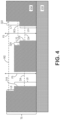
- FIGS. 3 and 4 are simplified cross-sectional views of alternative fixtures 212 and 312 with variable window counterbores 222 and 322, respectively.
- Fixtures 212 and 312, as well as preforms 214 and 314 can be substantially similar to each other, and to fixtures 12 and 112 and preforms 14 and 114, except as discussed below.
- Fixture 212 can include a variable thickness region partially overlapping with window counterbore 222, with thickness T3 ⁇ thickness T4 to correspond to a local rise in the profile of preform 214.
- a feature can be associated, for example, with a downward slope in an airfoil tip in the upstream to downstream direction.
- Window counterbore 222 overlaps with multiple holes 218, although only two are visible in FIG. 3 .
- Window counterbore 222 can have a width W1, and a length (not visible) orthogonal to W1.
- the depth, or length L3, of window counterbore 222 can be uniform along its area.
- a first hole 218 can have a length L4 and a second hole 218 can have a different length L5.
- L4 ⁇ L5.
- the sum of L3 and L4 can be equivalent to the length of flow path F2, and the sum of L3 and L5 can be equivalent to the length of flow path F3.
- Holes 218 can have uniform diameters D3.
- Fixture 312, depicted in FIG. 4 can have a uniform thickness T5, but a non-uniform window counterbore 322.
- Window counterbore 322 can similarly overlap with multiple holes 318 and have a width W2 and orthogonal length (not visible).
- Overlapping with a first hole 318 is a relatively shallow region of counterbore 322 having a depth, or length L6, and overlapping with a second hole 318 is a relatively deep region of counterbore 322 having length L7. Accordingly, L6 ⁇ L7.
- the positioning of the relatively shallow region adjacent the relatively deep region creates a stepped profile defining inset counterbore 324 having a width W3.
- Each hole 318 can have uniform diameters D4.
- window counterbore 322 can further create unequal hole lengths, with the first hole 318 having a length L8 and the second hole 318 having a length L9, where L8 > L9.
- Inset counterbore 324 can have a depth, or length L10 on at least one side.
- the sum of L6 and L8 is equivalent to flow path F5. Because of the uniform thickness of fixture 312, the sum of L7 and L9 is also equivalent to flow path F5, with the flow path (i.e., F5) being the same for both holes 318.
- a fixture can include one or more single counterbores 20 and/or 120 with one or more window counterbores 222 and/or 322.
- a fixture can further include a window counterbore with both a variable fixture thickness and non-uniform window, as shown in FIGS. 3 and 4 .
- a fixture can additionally have a uniform thickness and a uniform window counterbore (e.g., as shown in FIG. 1 ). Holes (e.g., 18, 118, 218, 318) need not have a uniform diameter across a fixture, and can further have non cylindrical geometries.
- the vaporous precursor flow path is not constrained to a uniform diameter along its entire length, rather, it has a wider portion (i.e., at the counterbore) and a narrower portion (i.e., at the hole).
- Such arrangement promotes improved mass transfer of vaporous precursor into and/or out of the preform during CVI.
- the particular hole diameter and counterbore dimension selected can be based on, for example, a desired relationship between L and D, where L is equivalent to the sum of the hole and counterbore lengths, and D is the combination of the hole and counterbore diameters and/or widths, as variously depicted in FIGS. 2-4 .
- any of the above fixtures can be formed from an existing tooling fixture with uniform, cylindrical holes. Holes directly aligned with the preform can be selected for counterboring to increase the flow and deposition rate of vaporous precursors. Window counterbores may be preferable for clusters of closely-grouped holes. Traditional counterbore bits can be used to form single counterbores, while machining (e.g., milling, drilling, etc.) can be used to create window counterbores, especially for graphite fixtures.
- the disclosed tooling assemblies can be used when infiltrating a preform, via CVI, to deposit interface coatings (e.g., layers of BN, SiC, Si-doped BN, etc.) and/or to form a matrix (e.g., SiC) to create a CMC part.
- interface coatings e.g., layers of BN, SiC, Si-doped BN, etc.
- matrix e.g., SiC
- Such CMC parts can be incorporated into aerospace, maritime, or industrial equipment, to name a few, non-limiting examples.
- a tooling assembly suitable for use in infiltrating a fibrous preform comprises a perforated fixture having a thickness.
- the fixture comprises a plurality of holes extending through the thickness, and a first counterbore aligned with at least one hole of the plurality of holes, the first counterbore having a first length extending partially through the thickness.
- the perforated fixture can be formed from at least one of graphite, a refractory metal alloy, a non-graphitic carbon material, and a ceramic material.
- the first counterbore can have a circular geometry with a first diameter.
- the at least one hole aligned with the counterbore can have a second diameter smaller than the first diameter.
- the at least one hole aligned with the first counterbore can have a second length, and a sum of the first length and the second length can be equal to the thickness of the fixture.
- Any of the above tooling assemblies can further include a second counterbore aligned with at least a second hole of the plurality of holes, the second counterbore having a second length extending partially through the thickness.
- the first counterbore can be aligned with a subset of the plurality of holes, the subset including at least three holes.
- the first counterbore can have a rectangular geometry.
- each hole of the subset can have a second length, and a sum of the first length and the second length can be equal to the thickness of the fixture.
- the thickness of the fixture can be non-uniform, and a first hole of the subset can have a first length, and a second hole of the subset can have a second length different from the first length.
- the first counterbore can have a first length and an oppositely disposed second length, the second length being greater than the first length.
- any of the above tooling assemblies can further include a second counterbore aligned with at least a second hole of the plurality of holes distinct from the subset, the second counterbore having a second length extending partially through the thickness.
- the first counterbore can have a circular geometry.
- the fixture can be configured to interface with a fibrous preform.
- the first counterbore and the at least one hole can be configured to align with the fibrous preform.
- the fibrous preform can be formed from silicon carbide.
- a method of counterboring a perforated fixture of a chemical vapor infiltration (CVI) tooling assembly comprises counterboring at least a first hole extending through a thickness of the perforated fixture, and counterboring at least a second hole extending through the thickness of the perforated fixture.
- CVI chemical vapor infiltration
- a tooling assembly suitable for use in infiltrating a fibrous preform comprises a perforated fixture having a thickness.
- the fixture comprises a plurality of holes extending through the thickness, a first counterbore aligned with at least one hole of the plurality of holes, the first counterbore having a first length extending partially through the thickness, and a second counterbore aligned with at least a second hole of the plurality of holes, the second counterbore having a second length extending partially through the thickness.
- the tooling assembly of the preceding paragraph can optionally include, additionally and/or alternatively, any one or more of the following features, configurations and/or additional components:
- the first counterbore can have a circular geometry and the second counterbore can have a rectangular geometry.
- the perforated fixture can be formed from at least one of graphite, a metallic material, a non-graphitic carbon material, and a ceramic material.
Landscapes
- Chemical & Material Sciences (AREA)
- Engineering & Computer Science (AREA)
- Materials Engineering (AREA)
- Organic Chemistry (AREA)
- Chemical Kinetics & Catalysis (AREA)
- General Chemical & Material Sciences (AREA)
- Mechanical Engineering (AREA)
- Metallurgy (AREA)
- Ceramic Engineering (AREA)
- Manufacturing & Machinery (AREA)
- Structural Engineering (AREA)
- Chemical Vapour Deposition (AREA)
Abstract
Description
- The present invention relates to chemical vapor infiltration (CVI), and more particularly to improved tooling for CVI.
- Ceramic matrix composite (CMC) parts are widely fabricated by densifying preforms made from woven fabrics or oriented/braided fiber tows. CVI is a commonly used densification technique practiced in industry. To keep the preforms in a rigid form and maintain proper shape and geometry, perforated tooling can be used to hold the preforms during the initial densification cycle(s). Holes in the tooling allow vaporous precursors to infiltrate into the preform for the deposition of a ceramic matrix. Tooling for simple preform can be designed with uniform hole lengths. When used with complexly-shaped preforms, such as turbine airfoils, such holes can be too long to allow vaporous precursors to sufficiently infiltrate the preform at certain locations. Thus, a need exists for improved tooling.
- From a first aspect, there is provided a tooling assembly suitable for use in infiltrating a fibrous preform that comprises a perforated fixture having a thickness. The fixture comprises a plurality of holes extending through the thickness, and a first counterbore aligned with at least one hole of the plurality of holes, the first counterbore having a first length extending partially through the thickness.
- From another aspect, there is provided a method of counterboring a perforated fixture of a chemical vapor infiltration (CVI) tooling assembly that comprises counterboring at least a first hole extending through a thickness of the perforated fixture, and counterboring at least a second hole extending through the thickness of the perforated fixture.
- From another aspect, which the Applicant expressly reserves the right to claim independently, there is provided a tooling assembly suitable for use in infiltrating a fibrous preform that comprises a perforated fixture having a thickness. The fixture comprises a plurality of holes extending through the thickness, a first counterbore aligned with at least one hole of the plurality of holes, the first counterbore having a first length extending partially through the thickness, and a second counterbore aligned with at least a second hole of the plurality of holes, the second counterbore having a second length extending partially through the thickness.
- Features of embodiments are set forth in the dependent claims.
-
-
FIG. 1 is a perspective view of a part of a tooling assembly with counterbores. -
FIG. 2 is a simplified cross-sectional illustration of a counterbore within the tooling assembly. -
FIG. 3 is a simplified cross-sectional illustration of a tooling assembly showing a first alternative counterbore. -
FIG. 4 is a simplified cross-sectional illustration of a tooling assembly showing a second alternative counterbore. - While the above-identified figures set forth one or more embodiments of the present disclosure, other embodiments are also contemplated, as noted in the discussion. In all cases, this disclosure presents the invention by way of representation and not limitation. It should be understood that numerous other modifications and embodiments can be devised by those skilled in the art, which fall within the scope and spirit of the principles of the invention. The figures may not be drawn to scale, and applications and embodiments of the present invention may include features and components not specifically shown in the drawings.
- This disclosure presents a CVI tooling assembly with varied hole lengths. More specifically, the disclosed assembly can include tooling fixtures with counterbored holes. Such design provides a flow path for vaporous precursors with an increased diameter along part of the hole relative to traditional designs with holes having uniform diameters.
-
FIG. 1 is a perspective view of a component oftooling assembly 10. More specifically,FIG. 1 showsfixture 12 oftooling assembly 10, which can be used to supportfibrous preform 14. In one embodiment,preform 14 can be an airfoil, and oppositely disposedfixtures 12 can be positioned at the outer diameter and inner diameter ends of the airfoil (e.g., of a blade or vane). In some embodiments,preform 14 can further include inner diameter (ID) and/or outer diameter (OD) platforms. Preform 14 can further be disposed aroundmandrel 16, one end of which is shown, and which can help removably engage preform 14 withfixture 12. In an exemplary embodiment,preform 14 can be formed from tows of silicon carbide (SiC) fibers arranged in one of various two or three-dimensional woven architectures such as plain, harness (e.g., 3, 5, 8, etc.), twill, braid, or non-symmetric to name a few non-limiting examples. In an alternative embodiment,preform 14 can be formed from non-woven (e.g., chopped, felted, etc.) fibers.Fixture 12 can be part of amulti-piece tooling assembly 10 comprising other fixtures 12 (e.g., cuboids, plates, etc.) in communication with various types and/or portions of a preform (e.g., preform 14).Fixture 12 can be formed from graphite in an exemplary embodiment. Portions offixture 12 can additionally and/or alternatively be formed from refractory metal alloys, non-graphitic forms of carbon (e.g., carbon-carbon composites) and/or ceramics (e.g., SiC). Such features can include, for example, locating pins. If included,mandrel 16 can also be formed from graphite. -
Fixture 12 can have a thickness, andmultiple infiltration holes 18 extending completely through thickness.Holes 18 permit the flow of vaporous precursors throughfixture 12 during CVI. Fixture 12 further includes multiple counterbores, more specifically,single counterbore 20 andwindow counterbore 22.Single counterbore 20 is aligned with an existinghole 18 and can have a corresponding rounded shape.Window counterbore 22 is aligned with/overlapsmultiple holes 18 and can have a rectangular shape. Other shapes for either type of counterbore are contemplated herein. Further, alternative embodiments can include exclusively one or moreindividual counterbores 20, and/or one ormore window counterbores 22. -
FIG. 2 is a simplified cross-sectional illustration of a portion offixture 112 withsingle counterbore 120 positioned overpreform 114. Fixture 112 andpreform 114 can be substantially similar tofixture 12 and preform 14, respectively, as described above. - As shown in
FIG. 2 ,counterbore 120 has a depth, or length, L1, and the remainder (i.e., non-counterbore portion) ofhole 118 has a length L2. The sum of L1 and L2 can be equivalent to thickness T1 offixture 112 at the location ofcounterbore 120 andhole 118. The sum of L1 and L2 can further be equivalent to the length of flow path F1, which represents the distance of the direct path for vaporous precursors travelling throughfixture 112 to reachpreform 114. Non-counterbore holes 118 (not shown inFIG. 2 ) can have a length L2 equivalent to T1. Length L1 ofvarious counterbores 120 withinfixture 112 need not be equal. Further,counterbore 120 can be relatively shallow, such that L1<L2, relatively deep, such that L1>L2, or can be formed such that L1=L2.Counterbore 120 can also have a diameter D1, and alignedhole 118 can have a smaller diameter D2. Although not shown inFIG. 2 ,fixture 112 can include one or more window counterbores with similar features, although such a counterbore could overlap withmultiple holes 118. -
FIGS. 3 and4 are simplified cross-sectional views ofalternative fixtures variable window counterbores Fixtures preforms fixtures -
Fixture 212, depicted inFIG. 3 , can include a variable thickness region partially overlapping withwindow counterbore 222, with thickness T3 < thickness T4 to correspond to a local rise in the profile ofpreform 214. Such a feature can be associated, for example, with a downward slope in an airfoil tip in the upstream to downstream direction.Window counterbore 222 overlaps withmultiple holes 218, although only two are visible inFIG. 3 .Window counterbore 222 can have a width W1, and a length (not visible) orthogonal to W1. The depth, or length L3, ofwindow counterbore 222 can be uniform along its area. Because of the varied thickness offixture 212, afirst hole 218 can have a length L4 and asecond hole 218 can have a different length L5. As shown, L4 < L5. The sum of L3 and L4 can be equivalent to the length of flow path F2, and the sum of L3 and L5 can be equivalent to the length of flow path F3. As shown, F2 < F3.Holes 218 can have uniform diameters D3. -
Fixture 312, depicted inFIG. 4 , can have a uniform thickness T5, but anon-uniform window counterbore 322.Window counterbore 322 can similarly overlap withmultiple holes 318 and have a width W2 and orthogonal length (not visible). Overlapping with afirst hole 318 is a relatively shallow region ofcounterbore 322 having a depth, or length L6, and overlapping with asecond hole 318 is a relatively deep region ofcounterbore 322 having length L7. Accordingly, L6 < L7. The positioning of the relatively shallow region adjacent the relatively deep region creates a stepped profile defininginset counterbore 324 having a width W3. Eachhole 318 can have uniform diameters D4. For thesecond hole 318 aligned withinset counterbore 324, D4 < W3 < W2. The features ofwindow counterbore 322 can further create unequal hole lengths, with thefirst hole 318 having a length L8 and thesecond hole 318 having a length L9, where L8 > L9. Insetcounterbore 324 can have a depth, or length L10 on at least one side. The sum of L6 and L8 is equivalent to flow path F5. Because of the uniform thickness offixture 312, the sum of L7 and L9 is also equivalent to flow path F5, with the flow path (i.e., F5) being the same for bothholes 318. - It is possible to include features of any or all of
FIGS. 1-4 in a single fixture without departing from the scope of the invention. For example, a fixture can include one or moresingle counterbores 20 and/or 120 with one ormore window counterbores 222 and/or 322. A fixture can further include a window counterbore with both a variable fixture thickness and non-uniform window, as shown inFIGS. 3 and4 . A fixture can additionally have a uniform thickness and a uniform window counterbore (e.g., as shown inFIG. 1 ). Holes (e.g., 18, 118, 218, 318) need not have a uniform diameter across a fixture, and can further have non cylindrical geometries. - Due to the combination of a single or window counterbore and an infiltration hole, the vaporous precursor flow path is not constrained to a uniform diameter along its entire length, rather, it has a wider portion (i.e., at the counterbore) and a narrower portion (i.e., at the hole). Such arrangement promotes improved mass transfer of vaporous precursor into and/or out of the preform during CVI. The particular hole diameter and counterbore dimension selected can be based on, for example, a desired relationship between L and D, where L is equivalent to the sum of the hole and counterbore lengths, and D is the combination of the hole and counterbore diameters and/or widths, as variously depicted in
FIGS. 2-4 . - Any of the above fixtures can be formed from an existing tooling fixture with uniform, cylindrical holes. Holes directly aligned with the preform can be selected for counterboring to increase the flow and deposition rate of vaporous precursors. Window counterbores may be preferable for clusters of closely-grouped holes. Traditional counterbore bits can be used to form single counterbores, while machining (e.g., milling, drilling, etc.) can be used to create window counterbores, especially for graphite fixtures.
- The disclosed tooling assemblies can be used when infiltrating a preform, via CVI, to deposit interface coatings (e.g., layers of BN, SiC, Si-doped BN, etc.) and/or to form a matrix (e.g., SiC) to create a CMC part. Such CMC parts can be incorporated into aerospace, maritime, or industrial equipment, to name a few, non-limiting examples.
- The following are non-exclusive descriptions of possible embodiments of the present invention.
- A tooling assembly suitable for use in infiltrating a fibrous preform comprises a perforated fixture having a thickness. The fixture comprises a plurality of holes extending through the thickness, and a first counterbore aligned with at least one hole of the plurality of holes, the first counterbore having a first length extending partially through the thickness.
- The tooling assembly of the preceding paragraph can optionally include, additionally and/or alternatively, any one or more of the following features, configurations and/or additional components:
In the above tooling assembly, the perforated fixture can be formed from at least one of graphite, a refractory metal alloy, a non-graphitic carbon material, and a ceramic material. - In any of the above tooling assemblies, the first counterbore can have a circular geometry with a first diameter.
- In any of the above tooling assemblies, the at least one hole aligned with the counterbore can have a second diameter smaller than the first diameter.
- In any of the above tooling assemblies, the at least one hole aligned with the first counterbore can have a second length, and a sum of the first length and the second length can be equal to the thickness of the fixture.
- Any of the above tooling assemblies can further include a second counterbore aligned with at least a second hole of the plurality of holes, the second counterbore having a second length extending partially through the thickness.
- In any of the above tooling assemblies, the first counterbore can be aligned with a subset of the plurality of holes, the subset including at least three holes.
- In any of the above tooling assemblies, the first counterbore can have a rectangular geometry.
- In any of the above tooling assemblies, each hole of the subset can have a second length, and a sum of the first length and the second length can be equal to the thickness of the fixture.
- In any of the above tooling assemblies, the thickness of the fixture can be non-uniform, and a first hole of the subset can have a first length, and a second hole of the subset can have a second length different from the first length.
- In any of the above tooling assemblies, the first counterbore can have a first length and an oppositely disposed second length, the second length being greater than the first length.
- Any of the above tooling assemblies can further include a second counterbore aligned with at least a second hole of the plurality of holes distinct from the subset, the second counterbore having a second length extending partially through the thickness.
- In any of the above tooling assemblies, the first counterbore can have a circular geometry.
- In any of the above tooling assemblies, the fixture can be configured to interface with a fibrous preform.
- In any of the above tooling assemblies, the first counterbore and the at least one hole can be configured to align with the fibrous preform.
- In any of the above tooling assemblies, the fibrous preform can be formed from silicon carbide.
- A method of counterboring a perforated fixture of a chemical vapor infiltration (CVI) tooling assembly comprises counterboring at least a first hole extending through a thickness of the perforated fixture, and counterboring at least a second hole extending through the thickness of the perforated fixture.
- A tooling assembly suitable for use in infiltrating a fibrous preform comprises a perforated fixture having a thickness. The fixture comprises a plurality of holes extending through the thickness, a first counterbore aligned with at least one hole of the plurality of holes, the first counterbore having a first length extending partially through the thickness, and a second counterbore aligned with at least a second hole of the plurality of holes, the second counterbore having a second length extending partially through the thickness.
- The tooling assembly of the preceding paragraph can optionally include, additionally and/or alternatively, any one or more of the following features, configurations and/or additional components:
In the above tooling assembly, the first counterbore can have a circular geometry and the second counterbore can have a rectangular geometry. - In any of the above tooling assemblies, the perforated fixture can be formed from at least one of graphite, a metallic material, a non-graphitic carbon material, and a ceramic material.
- While the invention has been described with reference to an exemplary embodiment(s), it will be understood by those skilled in the art that various changes may be made and equivalents may be substituted for elements thereof without departing from the scope of the invention. In addition, many modifications may be made to adapt a particular situation or material to the teachings of the invention without departing from the essential scope thereof. Therefore, it is intended that the invention not be limited to the particular embodiment(s) disclosed, but that the invention will include all embodiments falling within the scope of the appended claims.
Claims (15)
- A tooling assembly (10) suitable for use in infiltrating a fibrous preform (14; 114; 214; 314), the tooling assembly (10) comprising:
a perforated fixture (12; 112; 212; 312) having a thickness (T1; T3, T4; T5), the fixture (12; 112; 212; 312) comprising:a plurality of holes (18; 118; 218; 318) extending through the thickness (T1; T3, T4; T5); anda first counterbore (20; 22; 120; 222; 322) aligned with at least one hole (18; 118; 218; 318) of the plurality of holes (18; 118; 218; 318), the first counterbore having a first length (L1; L3; L6; L7) extending partially through the thickness (T1; T3, T4; T5). - The tooling assembly of claim 1, wherein the perforated fixture (12; 112; 212; 312) is formed from at least one of graphite, a metallic material, a refractory metal alloy, a non-graphitic carbon material, and a ceramic material.
- The tooling assembly of claim 1 or 2, wherein the first counterbore (20; 120) has a circular geometry with a first diameter (D1).
- The tooling assembly of claim 3, wherein the at least one hole (18; 118) aligned with the first counterbore (20; 120) has a second diameter (D2) smaller than the first diameter (D1).
- The tooling assembly of claim 4, wherein the at least one hole (18; 118) aligned with the first counterbore (20; 120) has a second length (L2), and wherein a sum of the first length (L1) and the second length (L2) is equal to the thickness (T1) of the fixture (112).
- The tooling assembly of any preceding claim, further comprising: a second counterbore (22; 222; 322); aligned with at least a second hole (18; 218; 318) of the plurality of holes (18; 118; 218; 318), the second counterbore (22; 222; 322) having a third length (L3; L6) extending partially through the thickness (T5).
- The tooling assembly of claim 1 or 2, wherein the first counterbore (22; 222; 322) is aligned with a subset (18; 218; 318) of the plurality of holes (18; 118; 218; 318), the subset (18; 218; 318) comprising at least three holes (18; 218; 318).
- The tooling assembly of claim 7, wherein the first counterbore (22; 222; 322) has a rectangular geometry.
- The tooling assembly of claim 7 or 8, wherein each hole (18; 218; 318) of the subset (18; 218; 318) has a second length (L4; L5; L8; L9), and wherein a sum of the first length (L3; L6; L7) and the second length (L4; L5; L8; L9) is equal to the thickness (T3, T4; T5) of the fixture (12; 212; 312).
- The tooling assembly of claim 7 or 8, wherein the thickness (T3; T4) of the fixture (12; 212) is non-uniform, and wherein a first hole (18; 218) of the subset (18; 218) has a fourth length (L4), and wherein a second hole (18; 218) of the subset (18; 218) has a fifth length (L5) different from the fourth length (L4).
- The tooling assembly of claim 7, 8 or 10, wherein the first counterbore (322) has a sixth length (L6) and an oppositely disposed seventh length (L7), the seventh length (L7) being greater than the sixth length (L6).
- The tooling assembly of any of claims 7 to 11, further comprising: a second counterbore (20; 120) aligned with at least a second hole (18; 118) of the plurality of holes (18; 118; 218; 318) distinct from the subset (18; 218; 318), the second counterbore (20; 120) having a counterbore length (L1) extending partially through the thickness (T1), wherein the second counterbore (20; 120) optionally has a circular geometry.
- The tooling assembly of any of claims 1 to 6, wherein the second counterbore (22; 122; 322) has a rectangular geometry.
- The tooling assembly of any preceding claim, wherein the fixture (12; 112; 212; 312) is configured to interface with a fibrous preform (14; 114; 214; 314), optionally wherein:the first counterbore (20; 22; 120; 222; 322) and the at least one hole (18; 118; 218; 318) are configured to align with the fibrous preform (14; 114; 214; 314); and/orthe fibrous preform (14; 114; 214; 314) is formed from silicon carbide.
- A method of counterboring a perforated fixture (12; 112; 212; 312) of a chemical vapor infiltration (CVI) tooling assembly (10), the method comprising:counterboring at least a first hole (18; 118; 218; 318) extending through a thickness (T1; T3, T4; T5) of the perforated fixture (12; 112; 212; 312); andcounterboring at least a second hole (18; 218; 318; 118) extending through the thickness (T3, T4; T5; T1) of the perforated fixture (12; 212; 312; 112).
Applications Claiming Priority (1)
| Application Number | Priority Date | Filing Date | Title |
|---|---|---|---|
| US17/957,613 US20240110280A1 (en) | 2022-09-30 | 2022-09-30 | Minimization of chemical vapor infiltration tooling hole length through counterbores |
Publications (1)
| Publication Number | Publication Date |
|---|---|
| EP4345185A1 true EP4345185A1 (en) | 2024-04-03 |
Family
ID=88236631
Family Applications (1)
| Application Number | Title | Priority Date | Filing Date |
|---|---|---|---|
| EP23199553.1A Pending EP4345185A1 (en) | 2022-09-30 | 2023-09-25 | Minimization of chemical vapor infiltration tooling hole length through counterbores |
Country Status (2)
| Country | Link |
|---|---|
| US (1) | US20240110280A1 (en) |
| EP (1) | EP4345185A1 (en) |
Citations (3)
| Publication number | Priority date | Publication date | Assignee | Title |
|---|---|---|---|---|
| CN110261256A (en) * | 2019-06-11 | 2019-09-20 | 上海大学 | A method of the measurement intrinsic deposition rate of CVD/CVI technique presoma |
| US20210101841A1 (en) * | 2019-10-08 | 2021-04-08 | Rolls-Royce High Temperature Composites Inc. | Assembly for chemical vapor infiltration of a fiber preform and method of infiltrating a fiber preform |
| US20210381384A1 (en) * | 2020-06-03 | 2021-12-09 | Raytheon Technologies Corporation | Multi-piece mandrel for cmc components |
Family Cites Families (7)
| Publication number | Priority date | Publication date | Assignee | Title |
|---|---|---|---|---|
| JPH02165621A (en) * | 1988-12-20 | 1990-06-26 | Hitachi Ltd | Liquid phase epitaxial growth method, semiconductor laser device manufacturing method, and liquid phase epitaxial growth jig |
| FR2882064B1 (en) * | 2005-02-17 | 2007-05-11 | Snecma Propulsion Solide Sa | PROCESS FOR THE DENSIFICATION OF THIN POROUS SUBSTRATES BY CHEMICAL VAPOR PHASE INFILTRATION AND DEVICE FOR LOADING SUCH SUBSTRATES |
| JP5604907B2 (en) * | 2010-02-25 | 2014-10-15 | 信越半導体株式会社 | Semiconductor substrate support susceptor for vapor phase growth, epitaxial wafer manufacturing apparatus, and epitaxial wafer manufacturing method |
| US9068265B2 (en) * | 2011-02-01 | 2015-06-30 | Applied Materials, Inc. | Gas distribution plate with discrete protective elements |
| KR20150113620A (en) * | 2014-03-31 | 2015-10-08 | 주성엔지니어링(주) | Gas distributing unit for apparatus treating substrate |
| FR3059679B1 (en) * | 2016-12-07 | 2021-03-12 | Safran Ceram | CONFORMATION TOOLS AND PLANT FOR CHEMICAL GAS INFILTRATION OF FIBROUS PREFORMS |
| CN114686976A (en) * | 2020-12-31 | 2022-07-01 | 上海新昇半导体科技有限公司 | Epitaxial base and epitaxial equipment |
-
2022
- 2022-09-30 US US17/957,613 patent/US20240110280A1/en active Pending
-
2023
- 2023-09-25 EP EP23199553.1A patent/EP4345185A1/en active Pending
Patent Citations (3)
| Publication number | Priority date | Publication date | Assignee | Title |
|---|---|---|---|---|
| CN110261256A (en) * | 2019-06-11 | 2019-09-20 | 上海大学 | A method of the measurement intrinsic deposition rate of CVD/CVI technique presoma |
| US20210101841A1 (en) * | 2019-10-08 | 2021-04-08 | Rolls-Royce High Temperature Composites Inc. | Assembly for chemical vapor infiltration of a fiber preform and method of infiltrating a fiber preform |
| US20210381384A1 (en) * | 2020-06-03 | 2021-12-09 | Raytheon Technologies Corporation | Multi-piece mandrel for cmc components |
Also Published As
| Publication number | Publication date |
|---|---|
| US20240110280A1 (en) | 2024-04-04 |
Similar Documents
| Publication | Publication Date | Title |
|---|---|---|
| CN102782256B (en) | Turbine engine blade made of composite material and method of manufacturing same | |
| US9453421B2 (en) | Apparatus having engineered surface feature and method to reduce wear and friction between CMC-to-metal attachment and interface | |
| EP4427896A1 (en) | Methods for complex geometry mandrel removal of ceramic matrix composite components | |
| EP4098417B1 (en) | Method of forming a ceramic matrix composite component having an internal cooling circuit | |
| EP4345185A1 (en) | Minimization of chemical vapor infiltration tooling hole length through counterbores | |
| EP4357114A1 (en) | Floating tooling assembly for chemical vapor infiltration | |
| EP3760604B1 (en) | Method of forming cooling channels in a ceramic matrix composite component | |
| EP4442856A2 (en) | Chemical vapor infiltration tooling for optimizing infiltration in ceramic matrix composites | |
| EP4428264A2 (en) | Chemical vapor infiltration tooling hole modification for optimizing infiltration in ceramic matrix composites | |
| EP4345186A1 (en) | Minimization of chemical vapor infiltration tooling holes length through windows | |
| EP4197776B1 (en) | Reinforcing fibers for use in ceramic matrix composites, methods of manufacture and articles comprising the same | |
| US12479775B2 (en) | Chemical vapor infiltration tooling for optimizing infiltration in ceramic matrix composites | |
| EP4345188A1 (en) | Ceramic matrix composite tooling for chemical vapor infiltration process | |
| US12473236B2 (en) | Internal tooling configuration for the creation of z-channels in woven ceramic matrix composite preforms | |
| US20240376017A1 (en) | Prefabricated noodle | |
| EP2535182A1 (en) | Method for manufacturing a composite surface | |
| EP4470740A1 (en) | Additively manufactured graphite tooling | |
| EP4549416A1 (en) | Variable z-channel hole pattern |
Legal Events
| Date | Code | Title | Description |
|---|---|---|---|
| PUAI | Public reference made under article 153(3) epc to a published international application that has entered the european phase |
Free format text: ORIGINAL CODE: 0009012 |
|
| STAA | Information on the status of an ep patent application or granted ep patent |
Free format text: STATUS: THE APPLICATION HAS BEEN PUBLISHED |
|
| AK | Designated contracting states |
Kind code of ref document: A1 Designated state(s): AL AT BE BG CH CY CZ DE DK EE ES FI FR GB GR HR HU IE IS IT LI LT LU LV MC ME MK MT NL NO PL PT RO RS SE SI SK SM TR |
|
| STAA | Information on the status of an ep patent application or granted ep patent |
Free format text: STATUS: REQUEST FOR EXAMINATION WAS MADE |
|
| 17P | Request for examination filed |
Effective date: 20240919 |
|
| RBV | Designated contracting states (corrected) |
Designated state(s): AL AT BE BG CH CY CZ DE DK EE ES FI FR GB GR HR HU IE IS IT LI LT LU LV MC ME MK MT NL NO PL PT RO RS SE SI SK SM TR |