EP4345078A1 - Reinforced glass, glass reinforcing method, and electronic device shell - Google Patents
Reinforced glass, glass reinforcing method, and electronic device shell Download PDFInfo
- Publication number
- EP4345078A1 EP4345078A1 EP22874764.8A EP22874764A EP4345078A1 EP 4345078 A1 EP4345078 A1 EP 4345078A1 EP 22874764 A EP22874764 A EP 22874764A EP 4345078 A1 EP4345078 A1 EP 4345078A1
- Authority
- EP
- European Patent Office
- Prior art keywords
- glass
- compressive stress
- strengthened glass
- strengthening
- layer
- Prior art date
- Legal status (The legal status is an assumption and is not a legal conclusion. Google has not performed a legal analysis and makes no representation as to the accuracy of the status listed.)
- Pending
Links
Images



Classifications
-
- C—CHEMISTRY; METALLURGY
- C03—GLASS; MINERAL OR SLAG WOOL
- C03C—CHEMICAL COMPOSITION OF GLASSES, GLAZES OR VITREOUS ENAMELS; SURFACE TREATMENT OF GLASS; SURFACE TREATMENT OF FIBRES OR FILAMENTS MADE FROM GLASS, MINERALS OR SLAGS; JOINING GLASS TO GLASS OR OTHER MATERIALS
- C03C21/00—Treatment of glass, not in the form of fibres or filaments, by diffusing ions or metals in the surface
- C03C21/001—Treatment of glass, not in the form of fibres or filaments, by diffusing ions or metals in the surface in liquid phase, e.g. molten salts, solutions
- C03C21/002—Treatment of glass, not in the form of fibres or filaments, by diffusing ions or metals in the surface in liquid phase, e.g. molten salts, solutions to perform ion-exchange between alkali ions
-
- C—CHEMISTRY; METALLURGY
- C03—GLASS; MINERAL OR SLAG WOOL
- C03C—CHEMICAL COMPOSITION OF GLASSES, GLAZES OR VITREOUS ENAMELS; SURFACE TREATMENT OF GLASS; SURFACE TREATMENT OF FIBRES OR FILAMENTS MADE FROM GLASS, MINERALS OR SLAGS; JOINING GLASS TO GLASS OR OTHER MATERIALS
- C03C4/00—Compositions for glass with special properties
- C03C4/18—Compositions for glass with special properties for ion-sensitive glass
-
- C—CHEMISTRY; METALLURGY
- C03—GLASS; MINERAL OR SLAG WOOL
- C03C—CHEMICAL COMPOSITION OF GLASSES, GLAZES OR VITREOUS ENAMELS; SURFACE TREATMENT OF GLASS; SURFACE TREATMENT OF FIBRES OR FILAMENTS MADE FROM GLASS, MINERALS OR SLAGS; JOINING GLASS TO GLASS OR OTHER MATERIALS
- C03C2203/00—Production processes
- C03C2203/50—After-treatment
-
- C—CHEMISTRY; METALLURGY
- C03—GLASS; MINERAL OR SLAG WOOL
- C03C—CHEMICAL COMPOSITION OF GLASSES, GLAZES OR VITREOUS ENAMELS; SURFACE TREATMENT OF GLASS; SURFACE TREATMENT OF FIBRES OR FILAMENTS MADE FROM GLASS, MINERALS OR SLAGS; JOINING GLASS TO GLASS OR OTHER MATERIALS
- C03C2204/00—Glasses, glazes or enamels with special properties
-
- C—CHEMISTRY; METALLURGY
- C03—GLASS; MINERAL OR SLAG WOOL
- C03C—CHEMICAL COMPOSITION OF GLASSES, GLAZES OR VITREOUS ENAMELS; SURFACE TREATMENT OF GLASS; SURFACE TREATMENT OF FIBRES OR FILAMENTS MADE FROM GLASS, MINERALS OR SLAGS; JOINING GLASS TO GLASS OR OTHER MATERIALS
- C03C2218/00—Methods for coating glass
- C03C2218/30—Aspects of methods for coating glass not covered above
- C03C2218/34—Masking
-
- Y—GENERAL TAGGING OF NEW TECHNOLOGICAL DEVELOPMENTS; GENERAL TAGGING OF CROSS-SECTIONAL TECHNOLOGIES SPANNING OVER SEVERAL SECTIONS OF THE IPC; TECHNICAL SUBJECTS COVERED BY FORMER USPC CROSS-REFERENCE ART COLLECTIONS [XRACs] AND DIGESTS
- Y02—TECHNOLOGIES OR APPLICATIONS FOR MITIGATION OR ADAPTATION AGAINST CLIMATE CHANGE
- Y02P—CLIMATE CHANGE MITIGATION TECHNOLOGIES IN THE PRODUCTION OR PROCESSING OF GOODS
- Y02P40/00—Technologies relating to the processing of minerals
- Y02P40/50—Glass production, e.g. reusing waste heat during processing or shaping
- Y02P40/57—Improving the yield, e-g- reduction of reject rates
Definitions
- the present disclosure relates to the field of strengthened glass technologies, and more specifically, to strengthened glass and a glass strengthening method, and an electronic device housing.
- Glass is widely used as a cover plate in the field of electronic products. With the development of electronic products toward a thinner and lighter direction, the mechanical performance of a glass cover plate is stricter. Chemical strengthening (that is, ion exchange) may be used to improve the mechanical performance of the glass. Large-radius ions in fused salt are used to replace small-radius ions on a surface of the glass, and a compressive stress layer with a specific thickness is formed on the surface of the glass. Although the compressive stress layer can hinder expansion of cracks in the glass, to improve a strength of the strengthened glass, a hindering effect of the compressive stress layer on expansion of microcracks is limited. Consequently, a mechanical strength of the glass is mainly affected by the microcracks on the surface and an interior of the glass. Therefore, it is necessary to provide a strengthening method that can effectively hinder the expansion of the microcracks and improve an intrinsic strength of the glass, so as to improve the mechanical performance of the strengthened glass.
- the present disclosure provides a glass strengthening method and a strengthened glass.
- a periodic surrounding compressive stress distribution is formed inside the glass and a uniform and dense surface compressive stress layer is formed on the surface layer, so as to achieve a multi-layer hindering effect on the glass surface and internal micro-crack expansion, reduce or even eliminate the impact of a single crack on the overall strength of the glass, and improve a fracture threshold, a bending strength, an impact resistant strength, and another mechanical performance of the glass.
- a first aspect of the present disclosure provides a strengthened glass.
- the strengthened glass includes a first surface and a second surface that are oppositely arranged, the first surface has a first surface compressive stress layer, and the second surface has a second surface compressive stress layer.
- the strengthened glass further includes a third stress layer sandwiched between the first surface compressive stress layer and the second surface compressive stress layer.
- the third stress layer includes a compressive stress region and multiple tensile stress regions spaced apart within the compressive stress region.
- the multiple tensile stress regions are arranged in a thickness direction perpendicular to the strengthened glass, and each of the tensile stress regions is surrounded by the compressive stress region.
- a sum of a maximum depth of the compressive stress region, a depth of the first surface compressive stress layer, and a depth of the second surface compressive stress layer is equal to a thickness of the strengthened glass.
- the thickness of the strengthened glass is 0.1 mm to 5 mm.
- the depth of the first surface compressive stress layer is 1% to 10% of the thickness of the strengthened glass; and the depth of the second surface compressive stress layer is 1% to 10% of the thickness of the strengthened glass.
- a surface compressive stress of the strengthened glass is greater than or equal to 500 MPa.
- a quantity of tensile stress regions is greater than or equal to 3.
- a compressive stress of the compressive stress region is less than the surface compressive stress of the strengthened glass; and the compressive stress of the compressive stress region is greater than or equal to 8 MPa.
- a bending strength of the strengthened glass is greater than or equal to 800 MPa.
- impact resistance energy of the strengthened glass is greater than or equal to 3J.
- a second aspect of the present disclosure provides a glass strengthening method, including the following steps:
- a total coverage rate of the multiple shielding layers on the first surface or the second surface is 10% to 70%.
- a quantity of shielding layers on the first surface or the second surface is greater than or equal to 3.
- strengthening time of the first chemical strengthening is 300 min or more.
- the first chemical strengthening uses fused salt including a sodium element, and a strengthening temperature is 350°C to 440°C.
- the second chemical strengthening uses fused salt including a potassium element, and a strengthening temperature is 350°C to 440°C.
- strengthening time of the second chemical strengthening is 10 min to 200 min.
- the inventor of the present disclosure found that a depth of stress layer (DOL) of an existing strengthened glass is relatively shallow, so that an effect of hindering expansion of microcracks is limited.
- the glass strengthening method provided in the embodiments of the present disclosure is simple in process, convenient in operation and high in controllable degree.
- a surface of the strengthened glass obtained by the strengthening method is provided with a surface compressive stress layer, and a compressive stress distribution surrounding the tensile stress region is provided inside the strengthened glass, so that an overall stress depth of the strengthened glass is relatively deep, and the mechanical performance is greatly improved.
- a third aspect of the present disclosure provides an electronic device housing.
- the electronic device housing includes the strengthened glass in the first aspect of the present disclosure, or includes the strengthened glass prepared by the glass method in the second aspect of the present disclosure.
- the electronic device housing having the strengthened glass can meet a requirement of thinning and lightening of an electronic device, and has good mechanical performance.
- An embodiment of the present disclosure provides a glass strengthening method, including the following steps:
- the glass substrate 10 includes the first surface 10a and the second surface 10b that are oppositely arranged. Multiple shielding layers 20 that are spaced apart are formed on the first surface 10a, and all the multiple shielding layers 20 are in direct contact with the first surface 10a. Multiple shielding layers 20 that are spaced apart are formed on the second surface 10b.
- the first surface 10a may be an upper surface of the glass substrate 10, and the second surface 10b may be a lower surface of the glass substrate 10.
- the shielding layer on the first surface 10a may be referred to as a first shielding layer
- the shielding layer on the second surface 10b may be referred to as a second shielding layer.
- the first shielding layer and the second shielding layer are arranged in one-to-one correspondence.
- each shielding layer on the second surface 10b corresponds to a second shielding layer on the first surface 10a (the two shielding layers completely overlap in a thickness direction of the glass substrate), or the first shielding layer and the second shielding layer are symmetrical with respect to the glass substrate 10.
- the first shielding layer and second shielding layer are in a one-to-one correspondence, which is beneficial to subsequently forming a symmetrical stress distribution on two opposing sides of the glass substrate.
- the shielding layer 20 may be formed on a surface of the glass substrate through a process such as screen printing, coating (for example, spraying), plating, or exposure and development.
- the shielding layer 20 is made of a high-temperature resistant material such as a high temperature resistant silicone material, synthetic rubber, or metal oxide.
- a pattern shape (which specifically refers to a projection shape of the shielding layer on the glass substrate) of the shielding layer 20 includes a regular shape such as a circle, an oval, a triangle, a rectangle, or a polygon, or an irregular shape.
- the shielding layers 20 are arranged spaced apart sequentially on the surface of the glass substrate. For example, the multiple shielding layers 20 may be arranged in an array shown in FIG.
- An existence of the shielding layer 20 divides the surface of the glass substrate into a shielded region and an exposed region (which is not covered by the shielding layer 20), and can prevent diffusion of ions in strengthened fused salt to the glass, for example, can prevent ion exchange inside the glass in the shielded region.
- a total coverage rate of the multiple shielding layers 20 on the first surface 10a or the second surface 10b of the glass substrate may be 10% to 70%.
- An area coverage rate of the shielding layer is within this range, which is helpful to implement a chemical strengthening effect described in step S02 below.
- the total coverage rate may be 15%, 20%, 25%, 30%, 40%, 50%, 60%, or 65%. In some implementations, the coverage rate is 20% to 50%.
- a quantity of shielding layers 20 on the first surface 10a or the second surface 10b is greater than or equal to 3. This is beneficial to forming a periodic surrounding compressive stress distribution in which multiple tensile stress regions 40 are wrapped at intervals inside the original compressive stress layer 30.
- the used glass substrate 10 is a glass including a Li element, so that two-step chemical strengthening can be performed.
- the glass substrate may be lithium aluminum silicate glass.
- a thickness of the glass substrate 11 may be 0.1 mm to 5 mm. This facilitates obtaining the original compressive stress layer 30 with a depth being equal to the thickness of the glass substrate by the following first chemical strengthening, and the strengthened glass does not still have poor mechanical performance due to an excessively thin thickness.
- the first chemical strengthening is generally to perform ion exchange in fused salt including a Na element, which is mainly Na + ⁇ Li + exchange.
- the second chemical strengthening is generally to perform ion exchange in fused salt including a K element, which is mainly K + ⁇ Na + exchange.
- the fused salt used for the first chemical strengthening may include the following components by mass percentage: 60% to 100% sodium salt and 0 to 40% potassium salt. In other words, the fused salt used for the first chemical strengthening may be only sodium salt, or a mixture of sodium salt and potassium salt.
- the sodium salt may be at least one of a nitrate, a sulfate, a chloride, or the like of the Na element, and generally, the nitrate is common.
- the potassium salt is similar to the sodium salt.
- the fused salt used for the first chemical strengthening is the sodium salt. Only the sodium salt is used for the first chemical strengthening, and a penetration distribution of Na + in the glass that is not covered by the shielding layer can be better implemented by using Na + with a relatively small ionic radius.
- the penetration distribution of Na + in the glass that is not covered by the shielding layer 20 can be implemented (that is, Na + is exchanged in an entire thickness direction of the glass that is not covered by the shielding layer (a Z direction shown in FIG. 2A , that is, a direction perpendicular to a glass surface provided with the shielding layer)).
- Na + in the fused salt may be further exchanged into the surface of the glass substrate covered by the shielding layer 20 (that is, Na + diffuses in a direction parallel to the glass surface provided with the shielding layer (an X direction shown in FIG. 2a )).
- the two parts jointly form the original compressive stress layer 30.
- Na + in the fused salt is difficult to be exchanged into the inside of the glass covered by the shielding layer 20, which becomes the tensile stress region 40.
- strengthening time of the first chemical strengthening may be controlled to be 300 min or more, so that a depth of a part of the original compressive stress layer 30 is equal to the thickness of the glass substrate 10.
- the strengthening time is 300 min to 600 min, for example, specifically 360 min, 420 min, 480 min, or 540 min.
- the original compressive stress layer 30 is a portion of the glass substrate in which first ion exchange occurs and may be considered as a sum of portions of the glass substrate other than the multiple tensile stress regions 40.
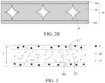
- the original compressive stress layer 30 may be further understood to include two parts. As shown in FIG. 2B , one part refers to a compressive stress layer part located on the surface of the glass substrate 10 (which is represented by a reference numeral 30a in FIG. 2B , and includes the surface of the glass substrate covered and uncovered by the shielding layer 20), and the other part refers to a compressive stress layer part located inside the glass substrate and surrounding the tensile stress region 40 (which is represented by a reference numeral 30b in FIG. 2B ).
- a periodic distribution of compressive stress-tensile stress is formed inside the glass.
- the tensile stress region 40 is spaced apart in the original compressive stress layer 30, and the tensile stress region 40 is surrounded by the original compressive stress layer 30, which helps to sufficiently hinder the expansion of the microcracks in the tensile stress region inside the glass, and compared with a glass substrate without chemical strengthening, the original pressure layer 30 formed by ion exchange changes a surrounding environment of the cracks in the region, passivates the cracks, and suppresses the expansion of the cracks in the region.
- the periodic distribution of the compressive/tension stress can also increase a strength limit threshold of the glass, thereby reducing the dispersion (the dispersion refers to non-uniform distribution of the glass strength) of the glass and improving the mechanical performance of the glass.
- the original compressive stress layer 30 may be considered as the sum of the portions of the glass substrate 10 other than the tensile stress region 40. It may be understood that the original compressive stress layer 30 is irregular in shape, and a depth (or thickness) of the original compressive stress layer is not uniform, but the depth of the original compressive stress layer 30 that is not covered by the shielding layer 20 is equal to the thickness of the glass substrate 10. This also indicates that after the first chemical strengthening, a relatively deep original compressive stress layer is formed, which helps to improve the mechanical performance of the glass substrate.
- a strengthening temperature of the first chemical strengthening is 350°C to 440°C.
- the strengthening temperature may be 390°C, 400°C, 420°C, 430°C, or the like.
- the glass substrate 10 with the shielding layer 20 may be preheated before the first chemical strengthening, and then the preheated glass substrate may be placed in the fused salt including the Na element for ion exchange. Preheating can prevent the glass substrate at room temperature from being directly placed into high-temperature strengthening liquid to crack, and reduce surface density of the glass substrate, which helps to increase a depth and a surface compressive stress value of the compressive stress layer obtained by chemical strengthening.
- the glass substrate may be preheated to a temperature of 320°C to 400°C. For example, the glass substrate is heated to 350°C, 360°C, 370°C, 380°C, 390°C, or the like.
- the shielding layer 20 may be removed by at least one of a mechanical polishing technique and soaking in a chemical solution.
- the used chemical solution is generally an alkaline solution, for example, a NaOH solution or a KOH solution.
- the alkaline solution may be heated (for example, 50°C to 70°C), to improve a removing speed of the shielding layer.
- step S04 the second chemical strengthening is performed on the glass substrate with the shielding layer being removed, so that ions (for example, K + ) with a relatively large ion radius may diffuse on the glass surface (as shown in FIG. 3 ), thereby further increasing the compressive stress on the glass surface (that is, forming surface compressive stress layers 31' and 31" with relatively high compressive stresses).
- ions for example, K +
- a sum of regions indicated by reference numerals 31', 31", and 32 is basically equal to the original compressive stress layer 30 in FIG. 2A .
- the depth of the surface compressive stress layer 31' or 31" may not be equal to the depth of the original compressive stress layer 30 that is formed on the surface of the glass substrate 10 covered by the shielding layer 20 in S02.
- the depth of the surface compressive stress layer may alternatively not be equal to the depth of the region 30a shown in FIG. 2B .
- the fused salt used for the second chemical strengthening may include the following components by mass percentage: 0 to 40% sodium salt and 60 to 100% potassium salt.
- the fused salt used for the second chemical strengthening may be only potassium salt, or a mixture of sodium salt and potassium salt.
- the fused salt used for the second chemical strengthening is the potassium salt.
- a strengthening temperature of the second chemical strengthening may be 350°C to 440°C, and strengthening time may be 10 min to 200 min.
- the strengthening temperature of the second chemical strengthening may be 390°C, 400°C, 420°C, 430°C, or the like.
- the strengthening time of the second chemical strengthening may be 30 min, 60 min, 90 min, 120 min, 150 min, 180 min, or the like.
- the strengthening time of the second chemical strengthening is relatively short, and a surface compressive stress layer with a relatively high compressive stress and even distribution can be formed in a relatively short time, and a time course of the entire strengthening process can be shortened in combination with the first chemical strengthening.
- the glass substrate may also be preheated before the second chemical strengthening to improve a strengthening effect.
- the glass substrate may be preheated to a temperature of 320°C to 400°C, for example, heated to 360°C, 370°C, 380°C, 390°C, or the like.
- the glass strengthening method provided in the embodiments of the present disclosure is simple in process, convenient in operation, and high in controllable degree.
- a surface of the strengthened glass obtained by the strengthening method is provided with a surface compressive stress layer, and a compressive stress distribution surrounding the tensile stress region is provided inside the strengthened glass, so that an overall stress depth of the strengthened glass is relatively deep, and the mechanical performance is greatly improved.
- the strengthened glass includes a first surface 10a and a second surface 10b that are oppositely arranged.
- the first surface 10a has a first surface compressive stress layer 31'
- the second surface 10b has a second surface compressive stress layer 31"
- a third stress layer is further sandwiched between the two surface compressive stress layers.
- the third stress layer includes a compressive stress region 32 and multiple tensile stress regions 40 spaced apart within the compressive stress region 32, the multiple tensile stress regions 40 are arranged in a thickness direction perpendicular to the strengthened glass, and each of the tensile stress regions 40 is surrounded by the compressive stress region 32.
- a sum of a maximum depth of the compressive stress region 32 located between two adjacent tensile stress regions 40, a depth of the first surface compressive stress layer 31', and a depth of the second surface compressive stress layer 31" is equal to a thickness T of the strengthened glass.
- the strengthened glass may be obtained by using the foregoing strengthening method in the present disclosure.
- the first surface compressive stress layer 31' extends from the first surface 10a to the inside by a specific depth h1
- the second surface compressive stress layer 31" extends from the second surface 10b to the inside by a specific depth h2.
- h1 may be equal to or may be different from h2.
- FIG. 4 shows that only the first surface 10a and the second surface 10b of the strengthened glass have surface compressive stress layers, glass-based strengthening treatment is generally performed by immersing in fused salt at a specific temperature. It may be understood that another surface of the strengthened glass further has a surface compressive stress layer with a specific depth.
- the multiple tensile stress regions 40 are spaced apart within the compressive stress region 32, to form a surrounding compressive stress distribution.
- the multiple tensile stress regions 40 are spaced apart in a direction parallel to the first surface 10a or the second surface 10b (that is, in the thickness direction perpendicular to the strengthened glass). It may be understood that, the compressive stress region 32 is of an irregular shape and a depth of the compressive stress region 32 is not uniform. Based on a fact that the multiple tensile stress regions 40 are spaced apart within the compressive stress region 32, the compressive stress region 32 may be considered as a layer in which a partial region is hollow. The hollow place is filled with tensile stress region 40.
- the depth of the compressive stress region 32 located between two adjacent tensile stress regions 40 is maximum, and a sum of the maximum depth of the compressive stress region and the depths of the two surface compressive stress layers on the first surface 10a and the second surface 10b is equal to the thickness T of the strengthened glass.
- a sum of a thickness of the third stress layer (that is, the maximum depth of the compressive stress region 32) and thicknesses of the two surface compressive stress layers 31' is equal to the thickness T of the strengthened glass.
- the surface compressive stress layer 31' is located on the surface of the strengthened glass, and the compressive stress region 32 is located inside the strengthened glass, it may be understood that a compressive stress of the surface compressive stress layer 31' is greater than a compressive stress of the compressive stress region 32.
- the compressive stress of the compressive stress region 32 inside the glass is greater than or equal to 8 MPa, for example, 8 MPa to 100 MPa.
- the surrounding compressive stress distribution inside the strengthened glass and the surface compressive stress layer having a relatively high stress value on the surface of the strengthened glass cause the cracks in the strengthened glass to be passivated, and the crack expansion is sufficiently hindered.
- the thickness T of the strengthened glass may be 0.1 mm to 5 mm. Therefore, when the strengthened glass is used as a housing of an electronic device (for example, a display screen cover plate, a camera protection cover plate, and a rear cover), the thickness of the strengthened glass is appropriate and can meet a requirement of lightening and thinning of the electronic device, and the mechanical performance of the strengthened is good.
- the thickness T may be 0.2 mm, 0.4 mm, 0.5 mm, 0.8 mm, 1 mm, 1.2 mm, 2 mm, 3 mm, 4 mm, or the like. In some implementations, the thickness T may be 0.1 mm to 1.2 mm. In this case, the electronic device using the strengthened glass is lighter and thinner.
- the depth of the first surface compressive stress layer 31' or the second surface compressive stress layer 31" is 1% to 10% of the thickness T of the strengthened glass.
- the compressive stress of the surface compressive stress layer of the strengthened glass is relatively high, and the compressive stress is relatively uniform.
- the depth h1 of the first surface compressive stress layer 31' or the depth h2 of the second surface compressive stress layer 31" is generally 1 ⁇ m to 50 ⁇ m.
- the depth h1 or h2 is 3 ⁇ m to 50 ⁇ m.
- the depth h1 or h2 is 5 ⁇ m, 10 ⁇ m, 20 ⁇ m, 30 ⁇ m, 40 ⁇ m, or the like.
- the surface compressive stress of the strengthened glass (that is, the compressive stress of the surface compressive stress layer 31' or 31") is greater than or equal to 500 MPa.
- a quantity of tensile stress regions 40 is greater than or equal to 3.
- An appropriate quantity of tensile stress regions is beneficial to forming a periodic surrounding compressive stress distribution inside the strengthened glass. It may be understood that the quantity of tensile stress regions 40 corresponds to a quantity of shielding layers on the first surface 10a or the second surface 10b.
- a bending strength of the strengthened glass is greater than or equal to 800 MPa.
- the bending strength refers to a maximum stress that can be withstood by an object when the object breaks under a bending load or reaches a specified bending moment. A higher bending strength indicates that the strengthened glass has better toughness and is less likely to break.
- the bending strength of the strengthened glass is 950 MPa to 1500 MPa. Further, the bending strength may be 950 MPa to 1200 MPa.
- impact resistance energy of the strengthened glass is greater than or equal to 3J.
- a relatively large impact strength indicates that the strengthened glass has strong impact resistance, is not easy to break, and has good toughness.
- the impact resistance energy of the strengthened glass is greater than or equal to 3.5J. In some embodiments, the impact resistance energy is 3.5J to 6J.
- An embodiment of the present disclosure further provides an electronic device housing.
- the electronic device housing includes the foregoing strengthened glass in the present disclosure, or includes the strengthened glass prepared by the foregoing glass method in the present disclosure.
- An electronic device using the electronic device housing may be various consumer electronic products, for example, a mobile phone, a tablet computer, a notebook computer, a wearable device (for example, a smartwatch or a smart band), a virtual reality (VR) terminal device, and an augmented reality (AR) terminal device, an e-reader, a television, a camcorder, and a projector.
- a mobile phone for example, a tablet computer, a notebook computer, a wearable device (for example, a smartwatch or a smart band), a virtual reality (VR) terminal device, and an augmented reality (AR) terminal device, an e-reader, a television, a camcorder, and a projector.
- a wearable device for example, a smartwatch or a smart band
- VR virtual reality
- AR augmented reality
- the electronic device is a portable electronic device such as a mobile phone, a tablet computer, or a wearable product.
- the electronic device housing may be a display cover plate assembled on a front side of the electronic device, the display cover plate may cover on a display module, or may be a rear cover assembled on a rear side of the electronic device.
- the electronic device housing may also be a camera protection cover plate.
- the strengthened glass is used as the housing of the electronic device, which can meet a requirement of lightening and thinning of the electronic device and has good mechanical performance.
- a glass strengthening method includes the following steps.
- FIG. 4 is a schematic structural diagram of a strengthened glass obtained in Embodiment 1.
- the upper surface and the lower surface of the strengthened glass each have a surface compressive stress layer with a thickness of 18 ⁇ m, and a surface compressive stress of the strengthened glass is 830 MPa.
- a glass strengthening method includes the following steps.
- FIG. 4 is a schematic structural diagram of a strengthened glass obtained in Embodiment 2.
- the upper surface and the lower surface of the strengthened glass each have a surface compressive stress layer with a thickness of 15 ⁇ m, and a surface compressive stress of the strengthened glass is 850 MPa.
- a glass strengthening method includes the following steps.
- FIG. 4 is a schematic structural diagram of a strengthened glass obtained in Embodiment 3.
- the upper surface and the lower surface of the strengthened glass each have a surface compressive stress layer with a thickness of 12 ⁇ m, and a surface compressive stress of the strengthened glass is 900 MPa.
- the shielding layer is a regular hexagon with a side length of 2 mm, and a spacing is 1.4 mm.
- the total coverage rate of the multiple shielding layers on the glass surface is 50%.
- FIG. 4 is a schematic structural diagram of a strengthened glass obtained in Embodiment 4.
- the upper surface and the lower surface of the strengthened glass each have a surface compressive stress layer with a thickness of 11 ⁇ m, and a surface compressive stress of the strengthened glass is 880 MPa.
- FIG. 4 is a schematic structural diagram of a strengthened glass obtained in Embodiment 5.
- the upper surface and the lower surface of the strengthened glass each have a surface compressive stress layer with a thickness of 30 ⁇ m, and a surface compressive stress of the strengthened glass is 650 MPa.
- a difference between a glass strengthening method and that in Embodiment 3 lies in that: the shielding layers that are spaced apart are not formed on the glass surface, and the entire glass is subject to first chemical strengthening in mixed fused salt including 60 wt% potassium nitrate and 40 wt% sodium nitrate, where the strengthening temperature is 380°C and the time is 120 min; and then the glass is subject to second chemical strengthening in mixed fused salt including 95 wt% potassium nitrate and 5 wt% sodium nitrate, where the strengthening temperature is 380°C and the time is 45 min.
- a difference between a glass strengthening method and that in Embodiment 3 lies in that: the shielding layers that are spaced apart are not formed on the glass surface. According to the method described in Embodiment 3, the first chemical strengthening and the second chemical strengthening are sequentially performed on the glass.
- Comparative Example 1 is a glass strengthening process commonly used in this field.
- the shielding layers that are spaced apart are formed on the glass surface before strengthening in neither Comparative Example 1 nor Comparative Example 2, and after the two-step chemical strengthening, a schematic structural diagram of an obtained strengthened glass is shown in FIG. 5 .
- a surface compressive stress layer with a relatively shallow depth is formed on only a surface of the strengthened glass. There is no compressive stress distribution inside the strengthened glass, and naturally there is no surrounding stress distribution emphasized in the present disclosure. Therefore, the mechanical performance of the strengthened glass in Embodiment 3 of the present disclosure are better than that in Comparative Example 1 and Comparative Example 2.
- the strengthened glass provided in the embodiments of the present disclosure is obviously superior to the strengthened glass in the comparative examples in terms of the bending strength, the impact resistant strength, and the like, which indicates that the mechanical performance of the strengthened glass provided in the present disclosure or the strengthened glass obtained by using the strengthening method provided in the present disclosure is significantly improved.
Landscapes
- Chemical & Material Sciences (AREA)
- Life Sciences & Earth Sciences (AREA)
- Engineering & Computer Science (AREA)
- Chemical Kinetics & Catalysis (AREA)
- General Chemical & Material Sciences (AREA)
- Geochemistry & Mineralogy (AREA)
- Materials Engineering (AREA)
- Organic Chemistry (AREA)
- Surface Treatment Of Glass (AREA)
- Casings For Electric Apparatus (AREA)
Abstract
Description
- The present disclosure claims priority to
Chinese Patent Application No. 202111157824.6, filed on September 29, 2021 - The present disclosure relates to the field of strengthened glass technologies, and more specifically, to strengthened glass and a glass strengthening method, and an electronic device housing.
- Glass is widely used as a cover plate in the field of electronic products. With the development of electronic products toward a thinner and lighter direction, the mechanical performance of a glass cover plate is stricter. Chemical strengthening (that is, ion exchange) may be used to improve the mechanical performance of the glass. Large-radius ions in fused salt are used to replace small-radius ions on a surface of the glass, and a compressive stress layer with a specific thickness is formed on the surface of the glass. Although the compressive stress layer can hinder expansion of cracks in the glass, to improve a strength of the strengthened glass, a hindering effect of the compressive stress layer on expansion of microcracks is limited. Consequently, a mechanical strength of the glass is mainly affected by the microcracks on the surface and an interior of the glass. Therefore, it is necessary to provide a strengthening method that can effectively hinder the expansion of the microcracks and improve an intrinsic strength of the glass, so as to improve the mechanical performance of the strengthened glass.
- Based on this, the present disclosure provides a glass strengthening method and a strengthened glass. Through a specific two-step chemical strengthening process, a periodic surrounding compressive stress distribution is formed inside the glass and a uniform and dense surface compressive stress layer is formed on the surface layer, so as to achieve a multi-layer hindering effect on the glass surface and internal micro-crack expansion, reduce or even eliminate the impact of a single crack on the overall strength of the glass, and improve a fracture threshold, a bending strength, an impact resistant strength, and another mechanical performance of the glass.
- A first aspect of the present disclosure provides a strengthened glass. The strengthened glass includes a first surface and a second surface that are oppositely arranged, the first surface has a first surface compressive stress layer, and the second surface has a second surface compressive stress layer. The strengthened glass further includes a third stress layer sandwiched between the first surface compressive stress layer and the second surface compressive stress layer. The third stress layer includes a compressive stress region and multiple tensile stress regions spaced apart within the compressive stress region. The multiple tensile stress regions are arranged in a thickness direction perpendicular to the strengthened glass, and each of the tensile stress regions is surrounded by the compressive stress region. A sum of a maximum depth of the compressive stress region, a depth of the first surface compressive stress layer, and a depth of the second surface compressive stress layer is equal to a thickness of the strengthened glass.
- Optionally, the thickness of the strengthened glass is 0.1 mm to 5 mm.
- Optionally, the depth of the first surface compressive stress layer is 1% to 10% of the thickness of the strengthened glass; and the depth of the second surface compressive stress layer is 1% to 10% of the thickness of the strengthened glass.
- Optionally, a surface compressive stress of the strengthened glass is greater than or equal to 500 MPa.
- Optionally, in the strengthened glass, a quantity of tensile stress regions is greater than or equal to 3.
- Optionally, a compressive stress of the compressive stress region is less than the surface compressive stress of the strengthened glass; and the compressive stress of the compressive stress region is greater than or equal to 8 MPa.
- Optionally, a bending strength of the strengthened glass is greater than or equal to 800 MPa.
- Optionally, impact resistance energy of the strengthened glass is greater than or equal to 3J.
- There is a surface compressive stress layer with a relatively high stress value on the surface of the strengthened glass, and a compressive stress is distributed throughout the thickness direction of the strengthened glass between the tensile stress regions, which makes a stress depth of the strengthened glass very deep. In addition, there is a surrounding compressive stress distribution of the compressive stress region surrounding the tensile stress region inside the strengthened glass, so that expansion of cracks in the strengthened glass is fully hindered, and the mechanical performance is better.
- A second aspect of the present disclosure provides a glass strengthening method, including the following steps:
- respectively forming multiple shielding layers that are spaced apart on a first surface and a second surface of a glass substrate that are oppositely arranged, where the shielding layers on the first surface are in a one-to-one correspondence with the shielding layers on the second surface;
- performing first chemical strengthening on the glass substrate with the shielding layer, to form an original compressive stress layer on a surface of the glass substrate that is covered by the shielding layer and on a surface and an interior of the glass substrate that are not covered by the shielding layer, and form multiple tensile stress regions inside a glass covered by the shielding layers, where the tensile stress region is surrounded by the original compressive stress layer, and a depth of the original compressive stress layer that is not covered by the shielding layer is equal to a thickness of the glass substrate;
- removing the shielding layers; and
- performing second chemical strengthening on the glass substrate after the shielding layers are removed to obtain a strengthened glass.
- Optionally, a total coverage rate of the multiple shielding layers on the first surface or the second surface is 10% to 70%.
- Optionally, a quantity of shielding layers on the first surface or the second surface is greater than or equal to 3.
- Optionally, when the thickness of the glass substrate is 0.5 mm or more, strengthening time of the first chemical strengthening is 300 min or more.
- Optionally, the first chemical strengthening uses fused salt including a sodium element, and a strengthening temperature is 350°C to 440°C.
- Optionally, the second chemical strengthening uses fused salt including a potassium element, and a strengthening temperature is 350°C to 440°C.
- Optionally, strengthening time of the second chemical strengthening is 10 min to 200 min.
- The inventor of the present disclosure found that a depth of stress layer (DOL) of an existing strengthened glass is relatively shallow, so that an effect of hindering expansion of microcracks is limited. The glass strengthening method provided in the embodiments of the present disclosure is simple in process, convenient in operation and high in controllable degree. A surface of the strengthened glass obtained by the strengthening method is provided with a surface compressive stress layer, and a compressive stress distribution surrounding the tensile stress region is provided inside the strengthened glass, so that an overall stress depth of the strengthened glass is relatively deep, and the mechanical performance is greatly improved.
- A third aspect of the present disclosure provides an electronic device housing. The electronic device housing includes the strengthened glass in the first aspect of the present disclosure, or includes the strengthened glass prepared by the glass method in the second aspect of the present disclosure.
- The electronic device housing having the strengthened glass can meet a requirement of thinning and lightening of an electronic device, and has good mechanical performance.
-
-
FIG. 1A is a schematic cross-sectional structural diagram of a glass substrate with a shielding layer; -
FIG. 1B is a top view of a glass substrate with a shielding layer; -
FIG. 2A is a schematic diagram of ion exchange of a glass substrate after first chemical strengthening; -
FIG. 2B is a schematic structural diagram of a glass substrate after first chemical strengthening; -
FIG. 3 is a schematic diagram of ion exchange of a glass substrate after second chemical strengthening; -
FIG. 4 is a schematic structural diagram of a strengthened glass according to an embodiment of the present disclosure; and -
FIG. 5 is a schematic structural diagram of a strengthened glass prepared in Comparative Example 1. - List of Reference Numerals: 10-Glass substrate, 20-Shielding layer, 30-Original compressive stress layer, 31'-First surface compressive stress layer, 31"-Second surface compressive stress layer, 32-Compressive stress region in a third stress layer, 40-Tensile stress region in a third stress layer.
- It should be noted that the following descriptions are merely exemplary embodiments of the present disclosure, and a person of ordinary skill in the art may make various improvements and modifications without departing from the spirit of embodiments of the present disclosure. All such improvements and refinements shall fall within the protection scope of the embodiments of the present disclosure.
- An embodiment of the present disclosure provides a glass strengthening method, including the following steps:
- S01. Referring to
FIG. 1A and FIG. 1B , multiple shielding layers 20 spaced apart are respectively formed on afirst surface 10a and asecond surface 10b of aglass substrate 10 that are oppositely arranged, where the shielding layers on thefirst surface 10a are in a one-to-one correspondence with the shielding layers on thesecond surface 10b. - S02. First chemical strengthening is performed on the
glass substrate 10 with the shielding layers 20, to form an originalcompressive stress layer 30 on a surface of theglass substrate 10 that is covered by the shielding layers 20 and on a surface and an interior of theglass substrate 10 that are not covered by the shielding layers 20, and form multipletensile stress regions 40 inside a glass covered by the shielding layers 20, where thetensile stress region 40 is surrounded by the originalcompressive stress layer 30, and a depth of the originalcompressive stress layer 30 that is not covered by theshielding layer 20 is equal to a thickness of the glass substrate 10 (referring toFIG. 2A ). - S03. The shielding layers 20 are removed.
- S04. Second chemical strengthening is performed on the
glass substrate 10 after the shielding layers 20 are removed to obtain a strengthened glass shown inFIG. 3 . - In step S01, the
glass substrate 10 includes thefirst surface 10a and thesecond surface 10b that are oppositely arranged. Multiple shielding layers 20 that are spaced apart are formed on thefirst surface 10a, and all the multiple shielding layers 20 are in direct contact with thefirst surface 10a. Multiple shielding layers 20 that are spaced apart are formed on thesecond surface 10b. Thefirst surface 10a may be an upper surface of theglass substrate 10, and thesecond surface 10b may be a lower surface of theglass substrate 10. For better distinction, the shielding layer on thefirst surface 10a may be referred to as a first shielding layer, and the shielding layer on thesecond surface 10b may be referred to as a second shielding layer. The first shielding layer and the second shielding layer are arranged in one-to-one correspondence. In other words, each shielding layer on thesecond surface 10b corresponds to a second shielding layer on thefirst surface 10a (the two shielding layers completely overlap in a thickness direction of the glass substrate), or the first shielding layer and the second shielding layer are symmetrical with respect to theglass substrate 10. In this way, the first shielding layer and second shielding layer are in a one-to-one correspondence, which is beneficial to subsequently forming a symmetrical stress distribution on two opposing sides of the glass substrate. - In an implementation of the present disclosure, the
shielding layer 20 may be formed on a surface of the glass substrate through a process such as screen printing, coating (for example, spraying), plating, or exposure and development. Theshielding layer 20 is made of a high-temperature resistant material such as a high temperature resistant silicone material, synthetic rubber, or metal oxide. A pattern shape (which specifically refers to a projection shape of the shielding layer on the glass substrate) of theshielding layer 20 includes a regular shape such as a circle, an oval, a triangle, a rectangle, or a polygon, or an irregular shape. The shielding layers 20 are arranged spaced apart sequentially on the surface of the glass substrate. For example, the multiple shielding layers 20 may be arranged in an array shown inFIG. 1B on the surface of the glass substrate, or may be arranged in another manner as required. An existence of theshielding layer 20 divides the surface of the glass substrate into a shielded region and an exposed region (which is not covered by the shielding layer 20), and can prevent diffusion of ions in strengthened fused salt to the glass, for example, can prevent ion exchange inside the glass in the shielded region. - In an implementation of the present disclosure, a total coverage rate of the multiple shielding layers 20 on the
first surface 10a or thesecond surface 10b of the glass substrate may be 10% to 70%. An area coverage rate of the shielding layer is within this range, which is helpful to implement a chemical strengthening effect described in step S02 below. For example, the total coverage rate may be 15%, 20%, 25%, 30%, 40%, 50%, 60%, or 65%. In some implementations, the coverage rate is 20% to 50%. - In the implementation of the present disclosure, a quantity of shielding
layers 20 on thefirst surface 10a or thesecond surface 10b is greater than or equal to 3. This is beneficial to forming a periodic surrounding compressive stress distribution in which multipletensile stress regions 40 are wrapped at intervals inside the originalcompressive stress layer 30. - In the present disclosure, the used
glass substrate 10 is a glass including a Li element, so that two-step chemical strengthening can be performed. For example, the glass substrate may be lithium aluminum silicate glass. Optionally, a thickness of the glass substrate 11 may be 0.1 mm to 5 mm. This facilitates obtaining the originalcompressive stress layer 30 with a depth being equal to the thickness of the glass substrate by the following first chemical strengthening, and the strengthened glass does not still have poor mechanical performance due to an excessively thin thickness. - In step S02 of the present disclosure, the first chemical strengthening is generally to perform ion exchange in fused salt including a Na element, which is mainly Na+→Li+ exchange. The second chemical strengthening is generally to perform ion exchange in fused salt including a K element, which is mainly K+→Na+ exchange. In step S02, the fused salt used for the first chemical strengthening may include the following components by mass percentage: 60% to 100% sodium salt and 0 to 40% potassium salt. In other words, the fused salt used for the first chemical strengthening may be only sodium salt, or a mixture of sodium salt and potassium salt. For example, the sodium salt may be at least one of a nitrate, a sulfate, a chloride, or the like of the Na element, and generally, the nitrate is common. The potassium salt is similar to the sodium salt. In an embodiment of the present disclosure, the fused salt used for the first chemical strengthening is the sodium salt. Only the sodium salt is used for the first chemical strengthening, and a penetration distribution of Na+ in the glass that is not covered by the shielding layer can be better implemented by using Na+ with a relatively small ionic radius.
- Relatively long first chemical strengthening is performed by using the spaced shielding layers, the penetration distribution of Na+ in the glass that is not covered by the
shielding layer 20 can be implemented (that is, Na+ is exchanged in an entire thickness direction of the glass that is not covered by the shielding layer (a Z direction shown inFIG. 2A , that is, a direction perpendicular to a glass surface provided with the shielding layer)). In addition, Na+ in the fused salt may be further exchanged into the surface of the glass substrate covered by the shielding layer 20 (that is, Na+ diffuses in a direction parallel to the glass surface provided with the shielding layer (an X direction shown inFIG. 2a )). The two parts jointly form the originalcompressive stress layer 30. In addition, due to the existence of theshielding layer 20, Na+ in the fused salt is difficult to be exchanged into the inside of the glass covered by theshielding layer 20, which becomes thetensile stress region 40. - In some implementations of the present disclosure, when a thickness of the glass substrate is 0.5 mm or more, strengthening time of the first chemical strengthening may be controlled to be 300 min or more, so that a depth of a part of the original
compressive stress layer 30 is equal to the thickness of theglass substrate 10. In some implementations, the strengthening time is 300 min to 600 min, for example, specifically 360 min, 420 min, 480 min, or 540 min. - In the present disclosure, the original
compressive stress layer 30 is a portion of the glass substrate in which first ion exchange occurs and may be considered as a sum of portions of the glass substrate other than the multipletensile stress regions 40. The originalcompressive stress layer 30 may be further understood to include two parts. As shown inFIG. 2B , one part refers to a compressive stress layer part located on the surface of the glass substrate 10 (which is represented by a reference numeral 30a inFIG. 2B , and includes the surface of the glass substrate covered and uncovered by the shielding layer 20), and the other part refers to a compressive stress layer part located inside the glass substrate and surrounding the tensile stress region 40 (which is represented by a reference numeral 30b inFIG. 2B ). - As shown in
FIG. 2A , after the first chemical strengthening, a periodic distribution of compressive stress-tensile stress is formed inside the glass. Thetensile stress region 40 is spaced apart in the originalcompressive stress layer 30, and thetensile stress region 40 is surrounded by the originalcompressive stress layer 30, which helps to sufficiently hinder the expansion of the microcracks in the tensile stress region inside the glass, and compared with a glass substrate without chemical strengthening, theoriginal pressure layer 30 formed by ion exchange changes a surrounding environment of the cracks in the region, passivates the cracks, and suppresses the expansion of the cracks in the region. In addition, the periodic distribution of the compressive/tension stress can also increase a strength limit threshold of the glass, thereby reducing the dispersion (the dispersion refers to non-uniform distribution of the glass strength) of the glass and improving the mechanical performance of the glass. - The original
compressive stress layer 30 may be considered as the sum of the portions of theglass substrate 10 other than thetensile stress region 40. It may be understood that the originalcompressive stress layer 30 is irregular in shape, and a depth (or thickness) of the original compressive stress layer is not uniform, but the depth of the originalcompressive stress layer 30 that is not covered by theshielding layer 20 is equal to the thickness of theglass substrate 10. This also indicates that after the first chemical strengthening, a relatively deep original compressive stress layer is formed, which helps to improve the mechanical performance of the glass substrate. - Optionally, a strengthening temperature of the first chemical strengthening is 350°C to 440°C. Specifically, the strengthening temperature may be 390°C, 400°C, 420°C, 430°C, or the like.
- In some implementations of the present disclosure, the
glass substrate 10 with theshielding layer 20 may be preheated before the first chemical strengthening, and then the preheated glass substrate may be placed in the fused salt including the Na element for ion exchange. Preheating can prevent the glass substrate at room temperature from being directly placed into high-temperature strengthening liquid to crack, and reduce surface density of the glass substrate, which helps to increase a depth and a surface compressive stress value of the compressive stress layer obtained by chemical strengthening. The glass substrate may be preheated to a temperature of 320°C to 400°C. For example, the glass substrate is heated to 350°C, 360°C, 370°C, 380°C, 390°C, or the like. - In step S03, the
shielding layer 20 may be removed by at least one of a mechanical polishing technique and soaking in a chemical solution. The used chemical solution is generally an alkaline solution, for example, a NaOH solution or a KOH solution. In addition, the alkaline solution may be heated (for example, 50°C to 70°C), to improve a removing speed of the shielding layer. - In step S04, the second chemical strengthening is performed on the glass substrate with the shielding layer being removed, so that ions (for example, K+) with a relatively large ion radius may diffuse on the glass surface (as shown in
FIG. 3 ), thereby further increasing the compressive stress on the glass surface (that is, forming surface compressive stress layers 31' and 31" with relatively high compressive stresses). There is also compressive stress distribution surrounding thetensile stress region 40 inside the glass, so that the mechanical performance of the obtained strengthened glass is better. - It can be learned from the comparison between
FIG. 3 andFIG. 2A that a sum of regions indicated byreference numerals 31', 31", and 32 is basically equal to the originalcompressive stress layer 30 inFIG. 2A . It may be understood that, the depth of the surfacecompressive stress layer 31' or 31" may not be equal to the depth of the originalcompressive stress layer 30 that is formed on the surface of theglass substrate 10 covered by theshielding layer 20 in S02. Certainly, the depth of the surface compressive stress layer may alternatively not be equal to the depth of the region 30a shown inFIG. 2B . - The fused salt used for the second chemical strengthening may include the following components by mass percentage: 0 to 40% sodium salt and 60 to 100% potassium salt. In other words, the fused salt used for the second chemical strengthening may be only potassium salt, or a mixture of sodium salt and potassium salt. In an embodiment of the present disclosure, the fused salt used for the second chemical strengthening is the potassium salt.
- In an implementation of the present disclosure, a strengthening temperature of the second chemical strengthening may be 350°C to 440°C, and strengthening time may be 10 min to 200 min. Specifically, the strengthening temperature of the second chemical strengthening may be 390°C, 400°C, 420°C, 430°C, or the like. The strengthening time of the second chemical strengthening may be 30 min, 60 min, 90 min, 120 min, 150 min, 180 min, or the like. In the present disclosure, the strengthening time of the second chemical strengthening is relatively short, and a surface compressive stress layer with a relatively high compressive stress and even distribution can be formed in a relatively short time, and a time course of the entire strengthening process can be shortened in combination with the first chemical strengthening.
- Similarly, the glass substrate may also be preheated before the second chemical strengthening to improve a strengthening effect. The glass substrate may be preheated to a temperature of 320°C to 400°C, for example, heated to 360°C, 370°C, 380°C, 390°C, or the like.
- The glass strengthening method provided in the embodiments of the present disclosure is simple in process, convenient in operation, and high in controllable degree. A surface of the strengthened glass obtained by the strengthening method is provided with a surface compressive stress layer, and a compressive stress distribution surrounding the tensile stress region is provided inside the strengthened glass, so that an overall stress depth of the strengthened glass is relatively deep, and the mechanical performance is greatly improved.
- An embodiment of the present disclosure further provides a strengthened glass. As shown in
FIG. 4 , the strengthened glass includes afirst surface 10a and asecond surface 10b that are oppositely arranged. Thefirst surface 10a has a first surface compressive stress layer 31', thesecond surface 10b has a second surfacecompressive stress layer 31", and a third stress layer is further sandwiched between the two surface compressive stress layers. The third stress layer includes acompressive stress region 32 and multipletensile stress regions 40 spaced apart within thecompressive stress region 32, the multipletensile stress regions 40 are arranged in a thickness direction perpendicular to the strengthened glass, and each of thetensile stress regions 40 is surrounded by thecompressive stress region 32. A sum of a maximum depth of thecompressive stress region 32 located between two adjacenttensile stress regions 40, a depth of the first surface compressive stress layer 31', and a depth of the second surfacecompressive stress layer 31" is equal to a thickness T of the strengthened glass. The strengthened glass may be obtained by using the foregoing strengthening method in the present disclosure. - Specifically, the first surface compressive stress layer 31' extends from the
first surface 10a to the inside by a specific depth h1, and the second surfacecompressive stress layer 31" extends from thesecond surface 10b to the inside by a specific depth h2. h1 may be equal to or may be different from h2. AlthoughFIG. 4 shows that only thefirst surface 10a and thesecond surface 10b of the strengthened glass have surface compressive stress layers, glass-based strengthening treatment is generally performed by immersing in fused salt at a specific temperature. It may be understood that another surface of the strengthened glass further has a surface compressive stress layer with a specific depth. - It can be learned from
FIG. 4 that the multipletensile stress regions 40 are spaced apart within thecompressive stress region 32, to form a surrounding compressive stress distribution. The multipletensile stress regions 40 are spaced apart in a direction parallel to thefirst surface 10a or thesecond surface 10b (that is, in the thickness direction perpendicular to the strengthened glass). It may be understood that, thecompressive stress region 32 is of an irregular shape and a depth of thecompressive stress region 32 is not uniform. Based on a fact that the multipletensile stress regions 40 are spaced apart within thecompressive stress region 32, thecompressive stress region 32 may be considered as a layer in which a partial region is hollow. The hollow place is filled withtensile stress region 40. The depth of thecompressive stress region 32 located between two adjacenttensile stress regions 40 is maximum, and a sum of the maximum depth of the compressive stress region and the depths of the two surface compressive stress layers on thefirst surface 10a and thesecond surface 10b is equal to the thickness T of the strengthened glass. A sum of a thickness of the third stress layer (that is, the maximum depth of the compressive stress region 32) and thicknesses of the two surface compressive stress layers 31' is equal to the thickness T of the strengthened glass. In addition, because the surface compressive stress layer 31' is located on the surface of the strengthened glass, and thecompressive stress region 32 is located inside the strengthened glass, it may be understood that a compressive stress of the surface compressive stress layer 31' is greater than a compressive stress of thecompressive stress region 32. Generally, the compressive stress of thecompressive stress region 32 inside the glass is greater than or equal to 8 MPa, for example, 8 MPa to 100 MPa. - Therefore, the surrounding compressive stress distribution inside the strengthened glass and the surface compressive stress layer having a relatively high stress value on the surface of the strengthened glass cause the cracks in the strengthened glass to be passivated, and the crack expansion is sufficiently hindered.
- In an implementation of the present disclosure, the thickness T of the strengthened glass may be 0.1 mm to 5 mm. Therefore, when the strengthened glass is used as a housing of an electronic device (for example, a display screen cover plate, a camera protection cover plate, and a rear cover), the thickness of the strengthened glass is appropriate and can meet a requirement of lightening and thinning of the electronic device, and the mechanical performance of the strengthened is good. Specifically, the thickness T may be 0.2 mm, 0.4 mm, 0.5 mm, 0.8 mm, 1 mm, 1.2 mm, 2 mm, 3 mm, 4 mm, or the like. In some implementations, the thickness T may be 0.1 mm to 1.2 mm. In this case, the electronic device using the strengthened glass is lighter and thinner.
- In an implementation of the present disclosure, the depth of the first surface compressive stress layer 31' or the second surface
compressive stress layer 31" is 1% to 10% of the thickness T of the strengthened glass. In this case, the compressive stress of the surface compressive stress layer of the strengthened glass is relatively high, and the compressive stress is relatively uniform. The depth h1 of the first surface compressive stress layer 31' or the depth h2 of the second surfacecompressive stress layer 31" is generally 1 µm to 50 µm. In some implementations, the depth h1 or h2 is 3 µm to 50 µm. For example, the depth h1 or h2 is 5 µm, 10 µm, 20 µm, 30 µm, 40 µm, or the like. In the present disclosure, the surface compressive stress of the strengthened glass (that is, the compressive stress of the surfacecompressive stress layer 31' or 31") is greater than or equal to 500 MPa. - In an implementation of the present disclosure, in the strengthened glass, a quantity of
tensile stress regions 40 is greater than or equal to 3. An appropriate quantity of tensile stress regions is beneficial to forming a periodic surrounding compressive stress distribution inside the strengthened glass. It may be understood that the quantity oftensile stress regions 40 corresponds to a quantity of shielding layers on thefirst surface 10a or thesecond surface 10b. - In an implementations of the present disclosure, a bending strength of the strengthened glass is greater than or equal to 800 MPa. The bending strength refers to a maximum stress that can be withstood by an object when the object breaks under a bending load or reaches a specified bending moment. A higher bending strength indicates that the strengthened glass has better toughness and is less likely to break. In some implementations, the bending strength of the strengthened glass is 950 MPa to 1500 MPa. Further, the bending strength may be 950 MPa to 1200 MPa.
- In an implementation of the present disclosure, impact resistance energy of the strengthened glass is greater than or equal to 3J. A relatively large impact strength indicates that the strengthened glass has strong impact resistance, is not easy to break, and has good toughness. In some implementations, the impact resistance energy of the strengthened glass is greater than or equal to 3.5J. In some embodiments, the impact resistance energy is 3.5J to 6J.
- An embodiment of the present disclosure further provides an electronic device housing. The electronic device housing includes the foregoing strengthened glass in the present disclosure, or includes the strengthened glass prepared by the foregoing glass method in the present disclosure.
- An electronic device using the electronic device housing may be various consumer electronic products, for example, a mobile phone, a tablet computer, a notebook computer, a wearable device (for example, a smartwatch or a smart band), a virtual reality (VR) terminal device, and an augmented reality (AR) terminal device, an e-reader, a television, a camcorder, and a projector.
- For example, the electronic device is a portable electronic device such as a mobile phone, a tablet computer, or a wearable product. Specifically, the electronic device housing may be a display cover plate assembled on a front side of the electronic device, the display cover plate may cover on a display module, or may be a rear cover assembled on a rear side of the electronic device. In some implementations, when the electronic device is an electronic device having a camera function (for example, a mobile phone or a digital camera), the electronic device housing may also be a camera protection cover plate.
- The strengthened glass is used as the housing of the electronic device, which can meet a requirement of lightening and thinning of the electronic device and has good mechanical performance.
- The present disclosure is further described in detail below through specific embodiments.
- A glass strengthening method includes the following steps.
- (1) A lithium aluminum silicate glass with a thickness of 0.6 mm is selected, and multiple high-temperature resistant shielding layers (with a thickness of 3 µm) spaced apart are printed on two opposing surfaces (for example, an upper surface and a lower surface) of the glass by using a screen printing process, to obtain a glass of which a surface is partially covered, where positions of the shielding layers on the upper surface and the lower surface of the glass are in a one-to-one correspondence, the shielding layer is a circle with a diameter of 1 mm and a center distance of 2 mm, a total coverage rate of the multiple shielding layers on each of the upper surface and the lower surface of the glass is 23%, and a quantity of shielding layers on each of the upper surface and the lower surface of the glass substrate is 3080.
- (2) The glass of which the surface is partially covered is preheated at 350°C and then subject to first chemical strengthening at 400°C in NaNO3 fused salt for 400 min to form an original compressive stress layer on a surface of the glass covered by the shielding layer and on a surface and an interior of the glass that are not covered by the shielding layer, and form multiple tensile stress regions inside a glass covered by the shielding layer, where the tensile stress region is surrounded by the original compressive stress layer, and a depth of the original compressive stress layer that is not covered by the shielding layer is 0.6 mm.
Then, a strengthened glass is taken out, cleaned, and dried. - (3) The glass that is strengthened for the first time is soaked in a NaOH solution at 70°C for 8 min to remove the shielding layer on the glass surface.
- (4) The glass after the shielding layer is removed is preheated at 380°C, and then is subject to second chemical strengthening at 400°C in KNO3 fused salt for 130 min, to obtain a strengthened glass, and the strengthened glass is cleaned and dried.
-
FIG. 4 is a schematic structural diagram of a strengthened glass obtained inEmbodiment 1. The upper surface and the lower surface of the strengthened glass each have a surface compressive stress layer with a thickness of 18 µm, and a surface compressive stress of the strengthened glass is 830 MPa. - A glass strengthening method includes the following steps.
- (1) A lithium aluminum silicate glass with a thickness of 0.6 mm is selected, and multiple high-temperature resistant shielding layers that are spaced apart are formed at corresponding positions of an upper surface and a lower surface of the glass by a screen printing process, to obtain a glass of which a surface is partially covered, where the shielding layer is a circle with a diameter of 1 mm and a center distance of 1.5 mm, a total coverage rate of the multiple shielding layers on each of the upper surface and the lower surface of the glass is 40%, and a quantity of shielding layers on each of the upper surface and the lower surface of the glass is 5350.
- (2) The glass of which the surface is partially covered is preheated at 380°C, and then is subject to first chemical strengthening at 420°C in NaNO3 fused salt for 350 min, to form an original compressive stress layer and multiple tensile stress regions that are similar to
Embodiment 1. After being cooled, the strengthened glass is taken out, cleaned, and dried. - (3) The shielding layer on the glass surface that is strengthened for the first time is removed by polishing.
- (4) The glass after the shielding layer is removed is preheated at 380°C, and then is subject to second chemical strengthening at 420°C in KNO3 fused salt for 80 min, to obtain a strengthened glass, and the strengthened glass is cleaned and dried.
-
FIG. 4 is a schematic structural diagram of a strengthened glass obtained in Embodiment 2. The upper surface and the lower surface of the strengthened glass each have a surface compressive stress layer with a thickness of 15 µm, and a surface compressive stress of the strengthened glass is 850 MPa. - A glass strengthening method includes the following steps.
- (1) A lithium aluminum silicate glass with a thickness of 0.6 mm is selected, and multiple high-temperature resistant shielding layers that are spaced apart are formed at corresponding positions of the upper surface and the lower surface of the glass by a screen printing process, to obtain a glass of which a surface is partially covered, where the shielding layer is a circle with a diameter of 2 mm and a center distance of 2.4 mm, a total coverage rate of the multiple shielding layers on each of the upper surface and the lower surface of the glass is 63%, and a quantity of shielding layers on each of the upper surface and the lower surface of the glass substrate is 2100.
- (2) The glass of which the surface is partially covered is preheated at 350°C, and then is subject to first chemical strengthening at 380°C in NaNO3 fused salt for 550 min, to form an original compressive stress layer and multiple tensile stress regions that are similar to those in
Embodiment 1. After being cooled, the strengthened glass is taken out, cleaned, and dried. - (3) The glass that is strengthened for the first time is soaked in a NaOH solution at 70°C for 8 min to remove the shielding layer on the glass surface.
- (4) The glass after the shielding layer is removed is preheated at 380°C, and then is subject to second chemical strengthening at 420°C in KNO3 fused salt for 50 min, to obtain a strengthened glass, and the strengthened glass is cleaned and dried.
-
FIG. 4 is a schematic structural diagram of a strengthened glass obtained in Embodiment 3. The upper surface and the lower surface of the strengthened glass each have a surface compressive stress layer with a thickness of 12 µm, and a surface compressive stress of the strengthened glass is 900 MPa. - A difference between a glass strengthening method and that in Embodiment 3 lies in that:
The thickness of the lithium aluminum silicate glass is 0.5 mm, the shielding layer is a regular hexagon with a side length of 2 mm, and a spacing is 1.4 mm. The total coverage rate of the multiple shielding layers on the glass surface is 50%. -
FIG. 4 is a schematic structural diagram of a strengthened glass obtained in Embodiment 4. The upper surface and the lower surface of the strengthened glass each have a surface compressive stress layer with a thickness of 11 µm, and a surface compressive stress of the strengthened glass is 880 MPa. - A difference between a glass strengthening method and that in Embodiment 3 lies in that: the first chemical strengthening adopts mixed fused salt including 60 wt% potassium nitrate and 40 wt% sodium nitrate; and the first chemical strengthening adopts mixed fused salt including 95 wt% potassium nitrate and 5 wt% sodium nitrate.
-
FIG. 4 is a schematic structural diagram of a strengthened glass obtained in Embodiment 5. The upper surface and the lower surface of the strengthened glass each have a surface compressive stress layer with a thickness of 30 µm, and a surface compressive stress of the strengthened glass is 650 MPa. - To highlight the beneficial effects of the embodiments of the present disclosure, the following provides comparative examples:
- A difference between a glass strengthening method and that in Embodiment 3 lies in that: the shielding layers that are spaced apart are not formed on the glass surface, and the entire glass is subject to first chemical strengthening in mixed fused salt including 60 wt% potassium nitrate and 40 wt% sodium nitrate, where the strengthening temperature is 380°C and the time is 120 min; and then the glass is subject to second chemical strengthening in mixed fused salt including 95 wt% potassium nitrate and 5 wt% sodium nitrate, where the strengthening temperature is 380°C and the time is 45 min.
- A difference between a glass strengthening method and that in Embodiment 3 lies in that: the shielding layers that are spaced apart are not formed on the glass surface. According to the method described in Embodiment 3, the first chemical strengthening and the second chemical strengthening are sequentially performed on the glass.
- Comparative Example 1 is a glass strengthening process commonly used in this field. The shielding layers that are spaced apart are formed on the glass surface before strengthening in neither Comparative Example 1 nor Comparative Example 2, and after the two-step chemical strengthening, a schematic structural diagram of an obtained strengthened glass is shown in
FIG. 5 . A surface compressive stress layer with a relatively shallow depth is formed on only a surface of the strengthened glass. There is no compressive stress distribution inside the strengthened glass, and naturally there is no surrounding stress distribution emphasized in the present disclosure. Therefore, the mechanical performance of the strengthened glass in Embodiment 3 of the present disclosure are better than that in Comparative Example 1 and Comparative Example 2. - To strongly support the beneficial effects of the embodiments of the present disclosure, a bending strength test and an impact resistance test are performed on the strengthened glass in the embodiments and the comparative examples. Results are shown in Table 1 below.
Table 1 Bending strength (MPa) Impact resistance energy (J) Embodiment 11030 3.8 Embodiment 2 980 4 Embodiment 3 1180 3.6 Embodiment 4 1250 3.5 Embodiment 5 960 3.5 Comparative Example 1 745 1.8 Comparative Example 2 650 1.5 - It can be learned from the Table 1 that the strengthened glass provided in the embodiments of the present disclosure is obviously superior to the strengthened glass in the comparative examples in terms of the bending strength, the impact resistant strength, and the like, which indicates that the mechanical performance of the strengthened glass provided in the present disclosure or the strengthened glass obtained by using the strengthening method provided in the present disclosure is significantly improved.
- The foregoing embodiments only describe several implementations of the present disclosure, which are described specifically and in detail, but cannot be construed as a limitation to the patent scope of the present disclosure. It should be noted that a person of ordinary skill in the art may make various changes and improvements without departing from the ideas of the present disclosure, which shall all fall within the protection scope of the present disclosure.
Claims (16)
- A strengthened glass,comprising a first surface and a second surface that are oppositely arranged, the first surface having a first surface compressive stress layer (31'), and the second surface having a second surface compressive stress layer (31"); andfurther comprising a third stress layer sandwiched between the first surface compressive stress layer (31') and the second surface compressive stress layer (31"),wherein the third stress layer comprises a compressive stress region (32) and a plurality of tensile stress regions (40) spaced apart within the compressive stress region (32), the plurality of tensile stress regions (40) are arranged in a thickness direction perpendicular to the strengthened glass, and each of the tensile stress regions (40) is surrounded by the compressive stress region (32); anda sum of a maximum depth of the compressive stress region (32), a depth of the first surface compressive stress layer (31'), and a depth of the second surface compressive stress layer (31") is equal to a thickness of the strengthened glass.
- The strengthened glass according to claim 1, wherein the thickness of the strengthened glass is 0.1 mm to 5 mm.
- The strengthened glass according to claim 1 or 2, whereinthe depth of the first surface compressive stress layer (31') is 1% to 10% of the thickness of the strengthened glass; andthe depth of the second surface compressive stress layer (31") is 1% to 10% of the thickness of the strengthened glass.
- The strengthened glass according to any one of claims 1 to 3, wherein a surface compressive stress of the strengthened glass is greater than or equal to 500 MPa.
- The strengthened glass according to any one of claims 1 to 4, wherein a quantity of tensile stress regions (40) in the strengthened glass is greater than or equal to 3.
- The strengthened glass according to any one of claims 1 to 5, whereina compressive stress of the compressive stress region (32) is less than the surface compressive stress of the strengthened glass; andthe compressive stress of the compressive stress region (32) is greater than or equal to 8 MPa.
- The strengthened glass according to any one of claims 1 to 6, wherein a bending strength of the strengthened glass is greater than or equal to 800 MPa.
- The strengthened glass according to any one of claims 1 to 6, wherein impact resistance energy of the strengthened glass is greater than or equal to 3J.
- A glass strengthening method, comprising the following steps:respectively forming a plurality of shielding layers (20) that are spaced apart on a first surface and a second surface of a glass substrate (10) that are oppositely arranged, wherein the shielding layers (20) on the first surface are in a one-to-one correspondence with the shielding layers (20) on the second surface;performing first chemical strengthening on the glass substrate (10) with the shielding layers, to form an original compressive stress layer (30) on a surface of the glass substrate (10) that is covered by the shielding layers (20) and on a surface and an interior of the glass substrate (10) that are not covered by the shielding layers (20), and form a plurality of tensile stress regions (40) inside a glass covered by the shielding layers (20), wherein the tensile stress region (40) is surrounded by the original compressive stress layer (30), and a depth of the original compressive stress layer (30) that is not covered by the shielding layer (20) is equal to a thickness of the glass substrate (10);removing the shielding layers (20); andperforming second chemical strengthening on the glass substrate (10) after the shielding layers (20) are removed to obtain a strengthened glass.
- The glass strengthening method according to claim 9, wherein a total coverage rate of the plurality of shielding layers (20) on the first surface or the second surface is 10% to 70%.
- The glass strengthening method according to claim 9 or 10, wherein a quantity of shielding layers (20) on the first surface or the second surface is greater than or equal to 3.
- The glass strengthening method according to any one of claims 9 to 11, wherein when the thickness of the glass substrate (10) is 0.5 mm or more, strengthening time of the first chemical strengthening is 300 min or more.
- The glass strengthening method according to claim 9 or 12, wherein the first chemical strengthening uses fused salt comprising a sodium element, and a strengthening temperature is 350°C to 440°C.
- The glass strengthening method according to any one of claims 9 to 13, wherein the second chemical strengthening uses fused salt comprising a potassium element, and a strengthening temperature is 350°C to 440°C.
- The glass strengthening method according to any one of claims 9 to 14, wherein strengthening time of the second chemical strengthening is 10 min to 200 min.
- An electronic device housing, comprising:the strengthened glass according to any one of claims 1 to 8; ora strengthened glass prepared by using the glass strengthening method according to any one of claims 9 to 15.
Applications Claiming Priority (2)
| Application Number | Priority Date | Filing Date | Title |
|---|---|---|---|
| CN202111157824.6A CN115872633B (en) | 2021-09-29 | 2021-09-29 | A tempered glass, a glass tempering method and an electronic equipment housing |
| PCT/CN2022/120561 WO2023051378A1 (en) | 2021-09-29 | 2022-09-22 | Reinforced glass, glass reinforcing method, and electronic device shell |
Publications (2)
| Publication Number | Publication Date |
|---|---|
| EP4345078A1 true EP4345078A1 (en) | 2024-04-03 |
| EP4345078A4 EP4345078A4 (en) | 2024-10-30 |
Family
ID=85756617
Family Applications (1)
| Application Number | Title | Priority Date | Filing Date |
|---|---|---|---|
| EP22874764.8A Pending EP4345078A4 (en) | 2021-09-29 | 2022-09-22 | Reinforced glass, glass reinforcing method, and electronic device shell |
Country Status (9)
| Country | Link |
|---|---|
| US (1) | US12617714B2 (en) |
| EP (1) | EP4345078A4 (en) |
| JP (1) | JP2024533007A (en) |
| KR (1) | KR102751797B1 (en) |
| CN (1) | CN115872633B (en) |
| AU (1) | AU2022353754B2 (en) |
| BR (1) | BR112023027680A2 (en) |
| TW (1) | TWI907727B (en) |
| WO (1) | WO2023051378A1 (en) |
Families Citing this family (1)
| Publication number | Priority date | Publication date | Assignee | Title |
|---|---|---|---|---|
| CN117292612B (en) * | 2023-09-08 | 2026-04-17 | 昆山国显光电有限公司 | Cover plate and display panel |
Family Cites Families (20)
| Publication number | Priority date | Publication date | Assignee | Title |
|---|---|---|---|---|
| JPH0791091B2 (en) * | 1989-11-06 | 1995-10-04 | 日本板硝子株式会社 | Method for manufacturing low-loss embedded waveguide |
| KR20100016231A (en) | 2007-04-27 | 2010-02-12 | 가부시키가이샤 엔티티 도코모 | Area forming method in designated base station, mobile station, and base station |
| US9302937B2 (en) * | 2010-05-14 | 2016-04-05 | Corning Incorporated | Damage-resistant glass articles and method |
| JP2013100195A (en) * | 2011-11-08 | 2013-05-23 | Luminous Optical Technology Co Ltd | Method that forms bearing stress layer pattern to surface of glass substrate, and glass substrate manufactured by the method |
| US20130122254A1 (en) * | 2011-11-11 | 2013-05-16 | Nai-Yue Liang | Method for manufacturing a patterned layer of compressive stress on a glass substrate and the glass substrate manufacturing by the method |
| CN102584027B (en) * | 2012-01-09 | 2014-10-29 | 宁波永新光学股份有限公司 | Method for coating anti-reflection film on chemically toughened optical glass surface |
| JP2014012611A (en) | 2012-07-03 | 2014-01-23 | Asahi Glass Co Ltd | Chemically strengthened glass plate |
| CN103803811A (en) * | 2012-11-09 | 2014-05-21 | 胜华科技股份有限公司 | Tempered glass structure and touch device with same |
| JP2014125360A (en) * | 2012-12-25 | 2014-07-07 | Nippon Electric Glass Co Ltd | Reinforced plate glass and production method thereof |
| US9931991B2 (en) * | 2013-11-21 | 2018-04-03 | Ford Global Technologies, Llc | Rotating garment hook |
| WO2016149860A1 (en) * | 2015-03-20 | 2016-09-29 | Schott Glass Technologies (Suzhou) Co. Ltd. | Thin glass article with a non-uniformly ion-exchanged surface layer and method for producing such a thin glass article |
| JP2018052803A (en) * | 2016-09-23 | 2018-04-05 | 日本電気硝子株式会社 | Strengthened glass plate, and production method thereof |
| WO2018056329A1 (en) * | 2016-09-23 | 2018-03-29 | 日本電気硝子株式会社 | Method for producing reinforced glass sheet, glass sheet for reinforcing, and reinforced glass sheet |
| CN106830709A (en) * | 2017-01-22 | 2017-06-13 | 南昌欧菲光学技术有限公司 | The processing method of glass substrate |
| JP7173011B2 (en) * | 2017-07-24 | 2022-11-16 | 日本電気硝子株式会社 | Chemically strengthened glass and method for producing chemically strengthened glass |
| CN109748518B (en) * | 2017-11-02 | 2022-12-27 | 重庆鑫景特种玻璃有限公司 | Tempered glass and manufacturing method thereof |
| US11639307B2 (en) * | 2018-07-13 | 2023-05-02 | Apple Inc. | Patterned asymmetric chemical strengthening |
| CN111099823B (en) * | 2018-10-25 | 2022-04-12 | 重庆鑫景特种玻璃有限公司 | Glass based on chemically strengthened pure glass and glass device |
| US11313997B2 (en) * | 2019-03-19 | 2022-04-26 | Momentum Optics Llc | Optical elements having gradient optical properties |
| CN111204991A (en) * | 2020-01-16 | 2020-05-29 | Oppo广东移动通信有限公司 | Glass cover plate and strengthening method thereof, and electronic equipment |
-
2021
- 2021-09-29 CN CN202111157824.6A patent/CN115872633B/en active Active
-
2022
- 2022-08-30 TW TW111132680A patent/TWI907727B/en active
- 2022-09-22 AU AU2022353754A patent/AU2022353754B2/en active Active
- 2022-09-22 KR KR1020237045436A patent/KR102751797B1/en active Active
- 2022-09-22 WO PCT/CN2022/120561 patent/WO2023051378A1/en not_active Ceased
- 2022-09-22 BR BR112023027680A patent/BR112023027680A2/en unknown
- 2022-09-22 JP JP2023577870A patent/JP2024533007A/en active Pending
- 2022-09-22 EP EP22874764.8A patent/EP4345078A4/en active Pending
-
2023
- 2023-12-28 US US18/398,698 patent/US12617714B2/en active Active
Also Published As
| Publication number | Publication date |
|---|---|
| EP4345078A4 (en) | 2024-10-30 |
| TWI907727B (en) | 2025-12-11 |
| TW202313514A (en) | 2023-04-01 |
| US12617714B2 (en) | 2026-05-05 |
| US20240140861A1 (en) | 2024-05-02 |
| CN115872633B (en) | 2025-02-11 |
| AU2022353754A1 (en) | 2024-01-18 |
| WO2023051378A1 (en) | 2023-04-06 |
| AU2022353754B2 (en) | 2026-02-12 |
| CN115872633A (en) | 2023-03-31 |
| BR112023027680A2 (en) | 2024-04-30 |
| KR102751797B1 (en) | 2025-01-10 |
| KR20240016357A (en) | 2024-02-06 |
| JP2024533007A (en) | 2024-09-12 |
Similar Documents
| Publication | Publication Date | Title |
|---|---|---|
| EP3955714B1 (en) | Housing assembly and preparation method thereof, and electronic device | |
| US12351508B2 (en) | Glass article and method for producing the same | |
| JP6313391B2 (en) | Glass substrate, cover glass for electronic device, and method for manufacturing glass substrate | |
| US20140370244A1 (en) | Cover glass and method of producing same | |
| KR20130124646A (en) | Method for cutting tempered glass | |
| US12617714B2 (en) | Strengthened glass and glass strengthening method, and electronic device housing | |
| US20200346975A1 (en) | Strengthened glass and manufacturing method therefor | |
| CN106830709A (en) | The processing method of glass substrate | |
| CN112456766B (en) | Curved ultra-thin glass, manufacturing method thereof and folding device | |
| JP2013125118A (en) | Cover glass for display | |
| CN112654192A (en) | Shell assembly, preparation method thereof and electronic equipment | |
| CN112592075B (en) | Glass cover plate, glass cover plate manufacturing method and electronic equipment | |
| US20240254038A1 (en) | Glass substrate, manufacturing method therefor, and electronic device | |
| CN111204991A (en) | Glass cover plate and strengthening method thereof, and electronic equipment | |
| CN112979181B (en) | Glass product and display device including the same | |
| CN104754079A (en) | Mobile phone shell and making method thereof | |
| JP2013121897A (en) | Cover glass for display | |
| EP2889277A1 (en) | Method for manufacturing touch device and resin composition thereof | |
| CN117800610A (en) | Electronic device, glass cover plate and preparation method thereof | |
| CN113698109A (en) | Glass shell strengthening method, electronic equipment shell and electronic equipment | |
| CN111302654A (en) | Single-side dominant compressive stress glass and preparation method and application thereof | |
| CN114125100A (en) | Electronic equipment, glass cover plate and preparation method thereof | |
| CN223458258U (en) | Coated glass cover plate | |
| CN206432389U (en) | A kind of antenna for mobile phone | |
| TW202000616A (en) | Curved tempered glass and method of manufacturing the same |
Legal Events
| Date | Code | Title | Description |
|---|---|---|---|
| STAA | Information on the status of an ep patent application or granted ep patent |
Free format text: STATUS: THE INTERNATIONAL PUBLICATION HAS BEEN MADE |
|
| PUAI | Public reference made under article 153(3) epc to a published international application that has entered the european phase |
Free format text: ORIGINAL CODE: 0009012 |
|
| STAA | Information on the status of an ep patent application or granted ep patent |
Free format text: STATUS: REQUEST FOR EXAMINATION WAS MADE |
|
| 17P | Request for examination filed |
Effective date: 20231229 |
|
| AK | Designated contracting states |
Kind code of ref document: A1 Designated state(s): AL AT BE BG CH CY CZ DE DK EE ES FI FR GB GR HR HU IE IS IT LI LT LU LV MC MK MT NL NO PL PT RO RS SE SI SK SM TR |
|
| A4 | Supplementary search report drawn up and despatched |
Effective date: 20240926 |
|
| RIC1 | Information provided on ipc code assigned before grant |
Ipc: C03C 21/00 20060101AFI20240920BHEP |
|
| DAV | Request for validation of the european patent (deleted) | ||
| DAX | Request for extension of the european patent (deleted) |