EP4345051A1 - Interlocking control circuit and double-tower type crane - Google Patents
Interlocking control circuit and double-tower type crane Download PDFInfo
- Publication number
- EP4345051A1 EP4345051A1 EP21943944.5A EP21943944A EP4345051A1 EP 4345051 A1 EP4345051 A1 EP 4345051A1 EP 21943944 A EP21943944 A EP 21943944A EP 4345051 A1 EP4345051 A1 EP 4345051A1
- Authority
- EP
- European Patent Office
- Prior art keywords
- tower
- primary
- control unit
- contact
- electrically connected
- Prior art date
- Legal status (The legal status is an assumption and is not a legal conclusion. Google has not performed a legal analysis and makes no representation as to the accuracy of the status listed.)
- Pending
Links
Images


Classifications
-
- B—PERFORMING OPERATIONS; TRANSPORTING
- B66—HOISTING; LIFTING; HAULING
- B66C—CRANES; LOAD-ENGAGING ELEMENTS OR DEVICES FOR CRANES, CAPSTANS, WINCHES, OR TACKLES
- B66C13/00—Other constructional features or details
- B66C13/18—Control systems or devices
- B66C13/40—Applications of devices for transmitting control pulses; Applications of remote control devices
- B66C13/44—Electrical transmitters
-
- B—PERFORMING OPERATIONS; TRANSPORTING
- B66—HOISTING; LIFTING; HAULING
- B66C—CRANES; LOAD-ENGAGING ELEMENTS OR DEVICES FOR CRANES, CAPSTANS, WINCHES, OR TACKLES
- B66C23/00—Cranes comprising essentially a beam, boom, or triangular structure acting as a cantilever and mounted for translatory of swinging movements in vertical or horizontal planes or a combination of such movements, e.g. jib-cranes, derricks, tower cranes
- B66C23/88—Safety gear
-
- B—PERFORMING OPERATIONS; TRANSPORTING
- B66—HOISTING; LIFTING; HAULING
- B66C—CRANES; LOAD-ENGAGING ELEMENTS OR DEVICES FOR CRANES, CAPSTANS, WINCHES, OR TACKLES
- B66C13/00—Other constructional features or details
- B66C13/18—Control systems or devices
-
- B—PERFORMING OPERATIONS; TRANSPORTING
- B66—HOISTING; LIFTING; HAULING
- B66C—CRANES; LOAD-ENGAGING ELEMENTS OR DEVICES FOR CRANES, CAPSTANS, WINCHES, OR TACKLES
- B66C13/00—Other constructional features or details
- B66C13/18—Control systems or devices
- B66C13/22—Control systems or devices for electric drives
-
- B—PERFORMING OPERATIONS; TRANSPORTING
- B66—HOISTING; LIFTING; HAULING
- B66C—CRANES; LOAD-ENGAGING ELEMENTS OR DEVICES FOR CRANES, CAPSTANS, WINCHES, OR TACKLES
- B66C23/00—Cranes comprising essentially a beam, boom, or triangular structure acting as a cantilever and mounted for translatory of swinging movements in vertical or horizontal planes or a combination of such movements, e.g. jib-cranes, derricks, tower cranes
- B66C23/18—Cranes comprising essentially a beam, boom, or triangular structure acting as a cantilever and mounted for translatory of swinging movements in vertical or horizontal planes or a combination of such movements, e.g. jib-cranes, derricks, tower cranes specially adapted for use in particular purposes
- B66C23/26—Cranes comprising essentially a beam, boom, or triangular structure acting as a cantilever and mounted for translatory of swinging movements in vertical or horizontal planes or a combination of such movements, e.g. jib-cranes, derricks, tower cranes specially adapted for use in particular purposes for use on building sites; constructed, e.g. with separable parts, to facilitate rapid assembly or dismantling, for operation at successively higher levels, for transport by road or rail
Definitions
- the present invention relates to the field of construction machinery, and in particular to an interlocking control circuit and a double-tower type crane.
- a double-tower type crane is shown in FIG. 1 and includes a primary tower 1, typically a flat boom tower, and a secondary tower 2, typically a movable-boom tower.
- a primary tower 1 typically a flat boom tower
- a secondary tower 2 typically a movable-boom tower.
- the main objective of the present invention is to provide an interlocking control circuit and a double-tower type crane, aiming at solving the technical problem of low safety during operation of the double-tower crane in the prior art.
- a first aspect of the present invention provides an interlocking control circuit applied to a double-tower type crane, the double-tower type crane including a primary tower and a secondary tower, and the interlocking control circuit includes:
- the interlocking switching unit includes:
- the primary tower control unit includes:
- the primary tower control unit further includes:
- the secondary tower control unit includes:
- the secondary tower control unit further includes:
- the interlocking control circuit further includes a five-core wire through which the interlocking switching unit communicates with the secondary tower control unit.
- the interlocking control circuit further includes a wireless communication unit through which the interlocking switching unit communicates with the secondary tower control unit.
- the primary tower control unit is further used for forbidding the interlocking switching unit to output the locking signal under the condition that the start-up of the primary tower is detected; and the secondary tower control unit is further used for forbidding the interlocking switching unit to output the locking signal under the condition that the start-up of the secondary tower is detected.
- a second aspect of the invention proposes a double-tower type crane including the interlocking control circuit as described above.
- the interlocking control circuit includes: a primary tower control unit provided on the primary tower; a secondary tower control unit provided on the secondary tower; an interlocking switching unit provided on the primary tower and separately communicating with the primary tower control unit and the secondary tower control unit.
- the interlocking switching unit is used for receiving a locking signal externally input, and sending the locking signal to the primary tower control unit and the secondary tower control unit.
- the primary tower control unit is used for controlling the primary tower to start, and the secondary tower control unit is used for forbidding the secondary tower to start; and under the condition that the locking signal indicates a second state, the primary tower control unit is used for forbidding the primary tower to start, and the secondary tower control unit is used for controlling the secondary tower to start.
- the described circuit design implements electric interlocking of the primary tower and the secondary tower, and improves the operation safety of the double-tower type crane.
- directionality indications such as up, down, left, right, front, back
- the directionality indications are used only for explaining the relative positional relationship, movement, etc. among components in a particular posture (as shown in the drawings), and if the particular posture is changed, the directionality indications are changed accordingly.
- the embodiments of the present invention provide an interlocking control circuit.
- the interlocking control circuit is applied to a double-tower type crane, the double-tower type crane includes a primary tower 1 and a secondary tower 2, the interlocking control circuit includes a primary tower control unit 100 provided on the primary tower 1; a secondary tower control unit 200 provided on the secondary tower 2; an interlocking switching unit 300 provided on the primary tower 1 and separately communicating with the primary tower control unit 100 and the secondary tower control unit 200; the interlocking switching unit 300 is used for receiving a locking signal externally input, and sending the locking signal to the primary tower control unit 100 and the secondary tower control unit 200; wherein, under the condition that the locking signal indicates a first state, the primary tower control unit 100 is used for controlling the primary tower 1 to start, and the secondary tower control unit 200 is used for forbidding the secondary tower 2 to start; and under the condition that the locking signal indicates a second state, the primary tower control unit 100 is used for forbidding the primary tower 1 to start, and the secondary tower control unit 200 is used for controlling the secondary
- both the primary tower control unit 100 and the interlocking switching unit 300 are provided in the primary tower 1, and in particular may be provided in a drive tank of a primary tower driver's cab, and a driver operates the interlocking switching unit 300 to control one of the primary tower 1 or the secondary tower 2 to start.
- the state of the locking signal may be 0 or 1, under the condition that the state of the locking signal is 1, the primary tower control unit 100 controls the primary tower 1 to start, and the secondary tower control unit 200 forbids the secondary tower 2 to start, under the condition that the state of the locking signal is 0, the primary tower control unit 100 forbids the primary tower 1 to start, and the secondary tower control unit 200 controls the secondary tower 2 to start.
- the interlocking control circuit further includes a five-core wire (not labeled) through which the interlocking switching unit 300 communicates with the secondary tower control unit 200 to transmit the interlocking signal to the secondary tower control unit 200.
- the interlocking control circuit may also include a wireless communication unit (not shown) through which the interlocking switching unit 300 communicates with the secondary tower control unit 200 to transmit the interlocking signal to the secondary tower control unit 200.
- the interlocking control circuit includes: a primary tower control unit provided on the primary tower; a secondary tower control unit provided on the secondary tower; an interlocking switching unit provided on the primary tower and separately communicating with the primary tower control unit and the secondary tower control unit.
- the interlocking switching unit is used for receiving a locking signal externally input, and sending the locking signal to the primary tower control unit and the secondary tower control unit.
- the primary tower control unit is used for controlling the primary tower to start, and the secondary tower control unit is used for forbidding the secondary tower to start; and under the condition that the locking signal indicates a second state, the primary tower control unit is used for forbidding the primary tower to start, and the secondary tower control unit is used for controlling the secondary tower to start.
- the described circuit design implements electric interlocking of the primary tower and the secondary tower, and improves the operation safety of the double-tower type crane.
- FIG. 4 is an alternative structure diagram of the interlocking switching unit 300 and the primary tower control unit 100 of FIG. 2
- FIG. 5 is an alternative structure diagram of the secondary tower control unit of FIG. 2 .
- the interlocking switching unit 300 includes: a two-position toggle switch SPZ, including a first normally open contact (not labeled)) and a first normally closed contact (not labeled)); a first contactor KM1, including a first coil (not labeled), a second normally open contact KM1-1 and a second normally closed contact KM1-2; and a second contactor KM2, including a second coil (not labeled), a third normally open contact KM2-1 and a third normally closed contact KM2-2; wherein, a first end of the first normally open contact is electrically connected with the first control end of the secondary tower control unit 200, a second end of the first normally open contact is electrically connected with the first end of the first coil, a first end of the first normally closed contact is connected with a first control end of the secondary tower control unit 200, a second end of the first normally closed contact is electrically connected with a first end of the second coil; a second end of the first coil is electrically connected with the first control end of the primary tower
- the two-position toggle switch SPZ is switched to the first normally open contact, the first normally open contact is closed, the first normally closed contact is opened, the locking signal indicates the first state, the primary tower control unit 100 controls the primary tower 1 to start, the primary tower 1 can perform normal operation, the secondary tower control unit 200 forbids the secondary tower 2 to start, and the secondary tower 2 is locked and can not be powered on.
- the two-position toggle switch SPZ is switched to the first normally closed contact
- the first normally open contact is opened
- the first normally closed contact is closed
- the lock signal indicates the second state
- the primary tower control unit 100 forbids the primary tower 1 to start
- the primary tower 1 is locked can not be powered on
- the secondary tower control unit 200 controls the secondary tower 2 to start, and the primary tower 1 can perform normal operation.
- the primary tower control unit 100 includes: a third contactor KM3, including a third coil, a first normally open auxiliary contact KM3-1, a first normally closed auxiliary contact KM3-2 and a first normally open primary contact (not shown); a fourth contactor KM4, including a fourth coil, a second normally open auxiliary contact KM4-1, a second normally closed auxiliary contact KM4-2 and a second normally open primary contact (not shown); a primary tower relay KT, including a fifth coil and a fourth normally closed contact KT-2; a first safety relay KMSC1, a first circuit breaker QFZ1, a second circuit breaker QFZ2; and a first reset button Fl; wherein a first pin A1 of the first safety relay KMSC1 is electrically connected with a second pin A2 of the first safety relay KMSC1 through the first normally open auxiliary contact KM3-1, the second normally open auxiliary contact KM4-1, and the fifth coil in sequence, a third pin A3 of the first safety relay KM
- the normally open primary contacts of the third contactor KM3 and the fourth contactor KM4 are both connected to the power supply of the primary tower 1, when the coils of the third contactor KM3 and the fourth contactor KM4 are electrified, the normally open primary contacts are closed, and the power supply of the primary tower 1 supplies power to the primary tower 1, thus starting the primary tower 1.
- the primary tower control unit 100 further includes: a primary tower emergency stop button SEM1; a primary tower phase sequence monitor relay KAP1; and a primary tower over-under-voltage detection relay KAU1; wherein a first end of the primary tower emergency stop button SEM1 is electrically connected with a ninth pin A9 of the first safety relay KMSC1, and a second end of the primary tower emergency stop button SEM1 is electrically connected with a tenth pin A10 of the first safety relay KMSC1 through a primary tower over-under-voltage detection relay KAU1 and a primary tower phase sequence monitor relay KAP1 in sequence.
- a primary tower emergency stop button SEM1 is electrically connected with a ninth pin A9 of the first safety relay KMSC1
- a second end of the primary tower emergency stop button SEM1 is electrically connected with a tenth pin A10 of the first safety relay KMSC1 through a primary tower over-under-voltage detection relay KAU1 and a primary tower phase sequence monitor relay KAP1 in sequence.
- the primary tower emergency stop button SEM1 may be one button or a plurality of buttons connected in series to the first safety relay KMSC1, and the present embodiment is not limited thereto.
- the primary tower emergency stop button SEM1 is used for the driver to input a primary tower emergency stop signal
- the primary tower phase sequence monitor relay KAP1 is used for detecting whether a power supply phase sequence of a primary tower loop is correct
- the primary tower over-under-voltage detection relay KAU1 is used for detecting whether the primary tower loop is over-under-voltage.
- the secondary tower control unit 200 includes: a fifth contactor KM5, including a sixth coil (not labeled), a third normally open auxiliary contact KM5-1, a third normally closed auxiliary contact KM5-2 and a third normally open primary contact (not shown); a sixth contactor KM6, including a seventh coil (not labeled), a fourth normally open auxiliary contact KM6-1, a fourth normally closed auxiliary contact KM6-2 and a fourth normally open primary contact (not shown); a secondary tower relay KL, including an eighth coil (not labeled) and a fifth normally closed contact KL-2; a second safety relay KMSC2; and a second reset button F2; wherein the first pin A1 of the second safety relay KMSC2 is electrically connected with the second pin A2 of the second safety relay KMSC2 through the third normally open auxiliary contact KM5-1, the fourth normally open auxiliary contact KM6-1, and the eighth coil in sequence, the third pin A3 of the second safety relay KMSC2 is electrically connected with the third
- the power supply of the secondary tower 2 supplies power to the secondary tower 2, so that the secondary tower 2 is started.
- the terminals of the five-core wire connected with the secondary tower control unit 200 are specifically: both ends C11-C12 of the normally closed contact of the secondary tower relay KL, both ends 49 (L)-48 (L) of the normally open contact of the first contactor KM1, and both ends 48 (L)-708 (L) of the normally closed contact of the second contactor KM2.
- the secondary tower control unit 200 further includes: a secondary tower emergency stop button SEM2; a secondary tower phase sequence monitor relay KAP2; and a secondary tower over-under-voltage detection relay KAU2; wherein a first end of the secondary tower emergency stop button SEM2 is electrically connected with a seventh pin A7 of the second safety relay KMSC2, and a second end of the secondary tower emergency stop button SEM2 is electrically connected with an eighth pin A8 of the second safety relay KMSC2 through the secondary tower phase sequence monitor relay KAP2 and a secondary tower over-under-voltage detection relay KAU2 in sequence.
- a secondary tower emergency stop button SEM2 is electrically connected with a seventh pin A7 of the second safety relay KMSC2
- a second end of the secondary tower emergency stop button SEM2 is electrically connected with an eighth pin A8 of the second safety relay KMSC2 through the secondary tower phase sequence monitor relay KAP2 and a secondary tower over-under-voltage detection relay KAU2 in sequence.
- the secondary tower emergency stop button SEM2 may be one button or a plurality of buttons connected in series to the second safety relay KMSC2, and the present embodiment is not limited thereto.
- the secondary tower emergency stop button SEM2 is used for the driver to input a secondary tower emergency stop signal
- the secondary tower phase sequence monitor relay KAP2 is used for detecting whether a power supply phase sequence of a secondary tower loop is correct
- the secondary tower over-under-voltage detection relay KAU2 is used for detecting whether the secondary tower loop is over-under-voltage.
- the primary tower control unit 100 controls the primary tower 1 to start and the secondary tower control unit 200 forbids the secondary tower 2 to start.
- the primary tower control unit 100 forbids the primary tower 1 to start and the secondary tower control unit 200 controls the secondary tower 2 to start.
- the embodiment solves the problem of electrical interlocking between the primary tower and the secondary tower with low cost, ensures that the primary tower and the secondary tower cannot run at the same time, and improves the reliability of the double-tower crane.
- the embodiments of the invention also provide a double-tower crane, the double-tower crane including the interlocking control circuit described in the above-mentioned embodiments.
- the circuit structure of the interlocking control circuit of the double-tower crane can refer to the above-mentioned embodiments and will not be described here. It can be understood that since the double-tower crane of the embodiments adopts the technical solution of the interlocking control circuit, the double-tower crane has all the beneficial effects.
Landscapes
- Engineering & Computer Science (AREA)
- Mechanical Engineering (AREA)
- Automation & Control Theory (AREA)
- Structural Engineering (AREA)
- Transportation (AREA)
- Control And Safety Of Cranes (AREA)
- Driving Mechanisms And Operating Circuits Of Arc-Extinguishing High-Tension Switches (AREA)
Abstract
Description
- This application claims the benefit of
Chinese Patent Application No. 202110625597.9, filed on June 04, 2021 - The present invention relates to the field of construction machinery, and in particular to an interlocking control circuit and a double-tower type crane.
- Tower cranes are widely used in all kinds of construction projects for hoisting all kinds of construction elements on the ground to the tops of building objects being built, which greatly improves the efficiency of operation. A double-tower type crane is shown in
FIG. 1 and includes aprimary tower 1, typically a flat boom tower, and asecondary tower 2, typically a movable-boom tower. When the double-tower type crane is operated, if the primary tower and the secondary tower are started at the same time, the equipment is prone to safety hazards due to weight imbalance, interference between the primary hook of the secondary tower and the structure of the primary tower. - The main objective of the present invention is to provide an interlocking control circuit and a double-tower type crane, aiming at solving the technical problem of low safety during operation of the double-tower crane in the prior art.
- In order to achieve the above objective, a first aspect of the present invention provides an interlocking control circuit applied to a double-tower type crane, the double-tower type crane including a primary tower and a secondary tower, and the interlocking control circuit includes:
- a primary tower control unit, provided on the primary tower;
- a secondary tower control unit, provided on the secondary tower;
- an interlocking switching unit, provided on the primary tower and separately communicating with the primary tower control unit and the secondary tower control unit;
- the interlocking switching unit is used for receiving a locking signal externally input, and sending the locking signal to the primary tower control unit and the secondary tower control unit;
- wherein, under the condition that the locking signal indicates a first state, the primary tower control unit is used for controlling the primary tower to start, and the secondary tower control unit is used for forbidding the secondary tower to start; and
- under the condition that the locking signal indicates a second state, the primary tower control unit is used for forbidding the primary tower to start, and the secondary tower control unit is used for controlling the secondary tower to start.
- Optionally, the interlocking switching unit includes:
- a two-position toggle switch, including a first normally open contact and a first normally closed contact;
- a first contactor, including a first coil, a second normally open contact and a second normally closed contact; and
- a second contactor, including a second coil, a third normally open contact and a third normally closed contact;
- wherein, a first end of the first normally open contact is electrically connected with a first control end of the secondary tower control unit, a second end of the first normally open contact is electrically connected with a first end of the first coil, a first end of the first normally closed contact is connected with a first control end of the secondary tower control unit, a second end of the first normally closed contact is electrically connected with a first end of the second coil;
- a second end of the first coil is electrically connected with the first control end of the primary tower control unit, the second normally open contact is separately electrically connected with a second control end of the primary tower control unit and the third normally closed contact, the second normally closed contact is separately electrically connected with a second control end of the secondary tower control unit and the third normally open contact; and
- a second end of the second coil is electrically connected with the first control end of the primary tower control unit, the third normally closed contact is further electrically connected with a third control end of the primary tower control unit, the third normally open contact is further electrically connected with a third control end of the secondary tower control unit.
- Optionally, the primary tower control unit includes:
- a third contactor, including a third coil, a first normally open auxiliary contact, a first normally closed auxiliary contact and a first normally open primary contact;
- a fourth contactor, including a fourth coil, a second normally open auxiliary contact, a second normally closed auxiliary contact and a second normally open primary contact;
- a primary tower relay, including a fifth coil and a fourth normally closed contact;
- a first safety relay, a first circuit breaker, a second circuit breaker; and
- a first reset button;
- wherein, a first pin of the first safety relay is electrically connected with a second pin of the first safety relay through the first normally open auxiliary contact, the second normally open auxiliary contact, and the fifth coil in sequence, a third pin of the first safety relay is electrically connected with a fourth pin of the first safety relay through the first normally closed auxiliary contact, the second normally closed auxiliary contact, the third normally closed contact, the second normally open contact, and the first reset button in sequence, a fifth pin of the first safety relay and a sixth pin of the first safety relay are both electrically connected with a first end of the first circuit breaker, a second end of the first circuit breaker is electrically connected with the first end of the first normally open contact through the fourth normally closed contact, and the first control end of the secondary tower control unit in sequence, a seventh pin of the first safety relay is electrically connected with a first end of the second circuit breaker through the third coil, and an eighth pin of the first safety relay is electrically connected with the first end of the second circuit breaker through the fourth coil;
- a second end of the second circuit breaker is separately electrically connected with the second end of the first coil and the second end of the second coil; and
- the first normally open primary contact and the second normally open primary contact are electrically connected with a power supply of the primary tower.
- Optionally, the primary tower control unit further includes:
- a primary tower emergency stop button;
- a primary tower over-under-voltage detection relay; and
- a primary tower phase sequence monitor relay;
- wherein, a first end of the primary tower emergency stop button is electrically connected with a ninth pin of the first safety relay, and a second end of the primary tower emergency stop button is electrically connected with a tenth pin of the first safety relay through the primary tower phase sequence monitor relay and the primary tower over-under-voltage detection relay in sequence.
- Optionally, the secondary tower control unit includes:
- a fifth contactor, including a sixth coil, a third normally open auxiliary contact, a third normally closed auxiliary contact and a third normally open primary contact;
- a sixth contactor, including a seventh coil, a fourth normally open auxiliary contact, a fourth normally closed auxiliary contact and a fourth normally open primary contact;
- a secondary tower relay, including an eighth coil and a fifth normally closed contact;
- a second safety relay; and
- a second reset button;
- wherein, a first pin of the second safety relay is electrically connected with a second pin of the second safety relay through the third normally open auxiliary contact, the fourth normally open auxiliary contact, and the eighth coil in sequence, a third pin of the second safety relay is electrically connected with a fourth pin of the second safety relay through the third normally closed auxiliary contact, the fourth normally closed auxiliary contact, the second normally closed contact, the third normally open contact, and the second reset button in sequence, a fifth pin of the second safety relay is electrically connected with the sixth coil, a sixth pin of the second safety relay is electrically connected with the seventh coil;
- a first end of the fifth normally closed contact is electrically connected with the fourth normally closed contact, a second end of the fifth normally closed contact is electrically connected with the first end of the first normally open contact; and
- the third normally open primary contact and the fourth normally open primary contact are electrically connected with a power supply of the secondary tower.
- Optionally, the secondary tower control unit further includes:
- a secondary tower emergency stop button;
- a secondary tower over-under-voltage detection relay; and
- a secondary tower phase sequence monitor relay;
- wherein, a first end of the secondary tower emergency stop button is electrically connected with a seventh pin of the second safety relay, a second end of the secondary tower emergency stop button is electrically connected with an eighth pin of the second safety relay through the secondary tower over-under-voltage detection relay, and the secondary tower phase sequence monitor relay in sequence.
- Optionally, the interlocking control circuit further includes a five-core wire through which the interlocking switching unit communicates with the secondary tower control unit.
- Optionally, the interlocking control circuit further includes a wireless communication unit through which the interlocking switching unit communicates with the secondary tower control unit.
- Optionally, the primary tower control unit is further used for forbidding the interlocking switching unit to output the locking signal under the condition that the start-up of the primary tower is detected; and
the secondary tower control unit is further used for forbidding the interlocking switching unit to output the locking signal under the condition that the start-up of the secondary tower is detected. - A second aspect of the invention proposes a double-tower type crane including the interlocking control circuit as described above.
- In the embodiments of the present invention, the interlocking control circuit includes: a primary tower control unit provided on the primary tower; a secondary tower control unit provided on the secondary tower; an interlocking switching unit provided on the primary tower and separately communicating with the primary tower control unit and the secondary tower control unit. The interlocking switching unit is used for receiving a locking signal externally input, and sending the locking signal to the primary tower control unit and the secondary tower control unit. Under the condition that the locking signal indicates a first state, the primary tower control unit is used for controlling the primary tower to start, and the secondary tower control unit is used for forbidding the secondary tower to start; and under the condition that the locking signal indicates a second state, the primary tower control unit is used for forbidding the primary tower to start, and the secondary tower control unit is used for controlling the secondary tower to start. The described circuit design implements electric interlocking of the primary tower and the secondary tower, and improves the operation safety of the double-tower type crane.
- To illustrate the technical solutions in the embodiments of the present invention or the prior art more clearly, the drawings required to be used in the description of the embodiments or the prior art will be briefly described below. It will be obvious that the drawings described below are only some embodiments of the invention, and other drawings may be obtained from the structure shown in these drawings without any creative effort by those of ordinary skill in the art.
-
FIG. 1 is a mechanical structure diagram of a double-tower type crane according to an embodiment of the present invention; -
FIG. 2 is a functional module diagram of an interlocking control circuit according to an embodiment of the present invention; -
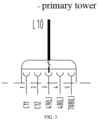
FIG. 3 is a schematic diagram of an interlocking signal connection of a primary tower and a secondary tower ofFIG. 2 ; -
FIG. 4 is an alternative structure diagram of an interlocking switching unit and a primary tower control unit ofFIG. 2 ; and -
FIG. 5 is an alternative structure diagram of a secondary tower control unit ofFIG. 2 . - Description of Reference Numerals:
1-primary tower, KMSC1-first safety relay, 2-secondary tower, QFZ1-first circuit breaker, 100-primary tower control unit, QFZ2-second circuit breaker, 200-secondary tower control unit, F1-first reset button, 300-interlocking switching unit, SEM1-primary tower emergency stop button, SPZ-two-position toggle switch, KAP1-primary tower phase sequence monitor relay, KM1-first contactor, KAU1-primary tower over-under-voltage detection relay, KM2-second contactor, KL-secondary tower relay, KM3-third contactor, KMSC2-second safety relay, KM4-fourth contactor, F2-second reset button, KM5-fifth contactor, SEM2-secondary tower emergency stop button, KM6-sixth contactor, KAP2-secondary tower phase sequence monitor relay, KT-primary tower relay, KAU2-secondary tower over-under-voltage detection relay. - Achievement of the objective, functional features and advantages of the present invention will be further explained with reference to the accompanying drawings.
- The technical solutions in the embodiments of the present invention will be clearly and completely described below in conjunction with the accompanying drawings in the embodiments of the present invention, it is obvious that the described embodiments are only a part of the embodiments of the present invention, rather than all of the embodiments. Based on the embodiments in the present invention, all other embodiments obtained by those of ordinary skill in the art without making inventive labor belong to the scope of protection of the present invention.
- It should be noted that, if the embodiments of the present invention relate to directionality indications (such as up, down, left, right, front, back...), the directionality indications are used only for explaining the relative positional relationship, movement, etc. among components in a particular posture (as shown in the drawings), and if the particular posture is changed, the directionality indications are changed accordingly.
- In addition, if there is description relating to "first", "second", etc. in the embodiments of the present invention, the description of "first", "second", etc. are for descriptive purposes only and cannot be understood as indicating or implying their relative importance or implying the number of technical features indicated. Thus, the features defined as "first", "second" may explicitly or implicitly include at least one of the features. In addition, the technical solutions among the various embodiments may be combined with each other, but must be on the basis that those of ordinary skill in the art can realize them. When the combination of technical solutions causes conflicts or cannot be realized, it should be considered that the combination of technical solutions does not exist and is not within the scope of protection claimed by the present invention.
- The embodiments of the present invention provide an interlocking control circuit.
- Referring to
FIG. 2 , in an embodiment, the interlocking control circuit is applied to a double-tower type crane, the double-tower type crane includes aprimary tower 1 and asecondary tower 2, the interlocking control circuit includes a primarytower control unit 100 provided on theprimary tower 1; a secondarytower control unit 200 provided on thesecondary tower 2; aninterlocking switching unit 300 provided on theprimary tower 1 and separately communicating with the primarytower control unit 100 and the secondarytower control unit 200; theinterlocking switching unit 300 is used for receiving a locking signal externally input, and sending the locking signal to the primarytower control unit 100 and the secondarytower control unit 200; wherein, under the condition that the locking signal indicates a first state, the primarytower control unit 100 is used for controlling theprimary tower 1 to start, and the secondarytower control unit 200 is used for forbidding thesecondary tower 2 to start; and under the condition that the locking signal indicates a second state, the primarytower control unit 100 is used for forbidding theprimary tower 1 to start, and the secondarytower control unit 200 is used for controlling thesecondary tower 2 to start. - It will be appreciated that both the primary
tower control unit 100 and theinterlocking switching unit 300 are provided in theprimary tower 1, and in particular may be provided in a drive tank of a primary tower driver's cab, and a driver operates theinterlocking switching unit 300 to control one of theprimary tower 1 or thesecondary tower 2 to start. - In a specific implementation, the state of the locking signal may be 0 or 1, under the condition that the state of the locking signal is 1, the primary
tower control unit 100 controls theprimary tower 1 to start, and the secondarytower control unit 200 forbids thesecondary tower 2 to start, under the condition that the state of the locking signal is 0, the primarytower control unit 100 forbids theprimary tower 1 to start, and the secondarytower control unit 200 controls thesecondary tower 2 to start. - Further, referring to
FIG. 3 together, the interlocking control circuit further includes a five-core wire (not labeled) through which theinterlocking switching unit 300 communicates with the secondarytower control unit 200 to transmit the interlocking signal to the secondarytower control unit 200. - Of course, the interlocking control circuit may also include a wireless communication unit (not shown) through which the
interlocking switching unit 300 communicates with the secondarytower control unit 200 to transmit the interlocking signal to the secondarytower control unit 200. - In the embodiments of the present invention, the interlocking control circuit includes: a primary tower control unit provided on the primary tower; a secondary tower control unit provided on the secondary tower; an interlocking switching unit provided on the primary tower and separately communicating with the primary tower control unit and the secondary tower control unit. The interlocking switching unit is used for receiving a locking signal externally input, and sending the locking signal to the primary tower control unit and the secondary tower control unit. Under the condition that the locking signal indicates a first state, the primary tower control unit is used for controlling the primary tower to start, and the secondary tower control unit is used for forbidding the secondary tower to start; and under the condition that the locking signal indicates a second state, the primary tower control unit is used for forbidding the primary tower to start, and the secondary tower control unit is used for controlling the secondary tower to start. The described circuit design implements electric interlocking of the primary tower and the secondary tower, and improves the operation safety of the double-tower type crane.
- Please refer to
FIGS. 2 ,4, and 5 , whereinFIG. 4 is an alternative structure diagram of theinterlocking switching unit 300 and the primarytower control unit 100 ofFIG. 2 , andFIG. 5 is an alternative structure diagram of the secondary tower control unit ofFIG. 2 . - In this embodiment, the interlocking switching unit 300 includes: a two-position toggle switch SPZ, including a first normally open contact (not labeled)) and a first normally closed contact (not labeled)); a first contactor KM1, including a first coil (not labeled), a second normally open contact KM1-1 and a second normally closed contact KM1-2; and a second contactor KM2, including a second coil (not labeled), a third normally open contact KM2-1 and a third normally closed contact KM2-2; wherein, a first end of the first normally open contact is electrically connected with the first control end of the secondary tower control unit 200, a second end of the first normally open contact is electrically connected with the first end of the first coil, a first end of the first normally closed contact is connected with a first control end of the secondary tower control unit 200, a second end of the first normally closed contact is electrically connected with a first end of the second coil; a second end of the first coil is electrically connected with the first control end of the primary tower control unit 100, the second normally open contact KM1-1 is separately electrically connected with a second control end of the primary tower control unit 100 and the third normally closed contact KM2-2, the second normally closed contact KM1-2 is separately electrically connected with a second control end of the secondary tower control unit 200 and the third normally open contact KM2-1; a second end of the second coil is electrically connected with the first control end of the primary tower control unit 100, the third normally closed contact KM2-2 is further electrically connected with a third control end of the primary tower control unit 100, and the third normally open contact KM2-1 is further electrically connected with a third control end of the secondary tower control unit 200.
- It should be noted that under the condition that the two-position toggle switch SPZ is switched to the first normally open contact, the first normally open contact is closed, the first normally closed contact is opened, the locking signal indicates the first state, the primary
tower control unit 100 controls theprimary tower 1 to start, theprimary tower 1 can perform normal operation, the secondarytower control unit 200 forbids thesecondary tower 2 to start, and thesecondary tower 2 is locked and can not be powered on. - Under the condition that the two-position toggle switch SPZ is switched to the first normally closed contact, the first normally open contact is opened, the first normally closed contact is closed, the lock signal indicates the second state, the primary
tower control unit 100 forbids theprimary tower 1 to start, theprimary tower 1 is locked can not be powered on, and the secondarytower control unit 200 controls thesecondary tower 2 to start, and theprimary tower 1 can perform normal operation. - Further, the primary tower control unit 100 includes: a third contactor KM3, including a third coil, a first normally open auxiliary contact KM3-1, a first normally closed auxiliary contact KM3-2 and a first normally open primary contact (not shown); a fourth contactor KM4, including a fourth coil, a second normally open auxiliary contact KM4-1, a second normally closed auxiliary contact KM4-2 and a second normally open primary contact (not shown); a primary tower relay KT, including a fifth coil and a fourth normally closed contact KT-2; a first safety relay KMSC1, a first circuit breaker QFZ1, a second circuit breaker QFZ2; and a first reset button Fl; wherein a first pin A1 of the first safety relay KMSC1 is electrically connected with a second pin A2 of the first safety relay KMSC1 through the first normally open auxiliary contact KM3-1, the second normally open auxiliary contact KM4-1, and the fifth coil in sequence, a third pin A3 of the first safety relay KMSC1 is electrically connected with a fourth pin A4 of the first safety relay KMSC1 through the first normally closed auxiliary contact KM3-2, the second normally closed auxiliary contact KM4-2, the third normally closed contact KM2-2, the second normally open contact KM1-1, and the first reset button F1 in sequence, a fifth pin A5 of the first safety relay KMSC1 and a sixth pin A6 of the first safety relay KMSC1 are both electrically connected with a first end of the first circuit breaker QFZ1, a second end of the first circuit breaker QFZ1 is electrically connected with the first end of the first normally open contact through the fourth normally closed contact KT-2, and the first control end of the secondary tower control unit 200 in sequence, a seventh pin A7 of the first safety relay KMSC1 is electrically connected with the first end of the second circuit breaker QFZ2 through a third coil, the eighth pin A8 of the first safety relay KMSC1 is electrically connected with a first end of the second circuit breaker QFZ2 through a fourth coil; a second end of the second circuit breaker QFZ2 is separately electrically connected with a second end of the first coil and a second end of the second coil; the first normally open primary contact and the second normally open primary contact are electrically connected with a power supply (not shown) of the primary tower.
- It should be understood that when the
primary tower 1 and thesecondary tower 2 are not started, and the two-position toggle switch SPZ is switched to the first normally open contact, the coil of the first contactor KM1 is electrified, and the normally open contact KM1-1 of the first contactor KM1 is closed. When the driver presses the first reset button F1, the third pin A3 and the fourth pin A4 of the first safety relay KMSC1 are conducted, and the seventh pin A7 and the eighth pin A8 controlled by the first safety relay KMSC1 output electrical signals, so that the coils of the third contactor KM3 and the fourth contactor KM4 are electrified. Since the normally open primary contacts of the third contactor KM3 and the fourth contactor KM4 are both connected to the power supply of theprimary tower 1, when the coils of the third contactor KM3 and the fourth contactor KM4 are electrified, the normally open primary contacts are closed, and the power supply of theprimary tower 1 supplies power to theprimary tower 1, thus starting theprimary tower 1. - When the
primary tower 1 is started, the normally open auxiliary contact KM3-1 of the third contactor KM3 and the normally open auxiliary contact KM4-1 of the fourth contactor KM4 are closed, the coil of the primary tower relay KT is electrified, the normally closed contact KT-2 of the primary tower relay KT is opened, and the coils of the first contactor KM1 and the second contactor KM2 are not electrified. At this time, no matter which contact the two-position toggle switch SPZ is switched to, the operation switching between theprimary tower 1 and thesecondary tower 2 cannot be realized. - When the
primary tower 1 and thesecondary tower 2 are not started and the two-position toggle switch SPZ is switched to the first normally closed contact, the coil of the second contactor KM2 is electrified, the normally closed contact KM2-2 of the second contactor KM2 is opened, the third pin A3 and the fourth pin A4 of the first safety relay KMSC1 are not conducted, and the first safety relay KMSC1 controls the seventh pin A7 and the eighth pin A8 to have no electrical signal output, so that the third contactor KM3 and the fourth contactor KM4 are not electrified and theprimary tower 1 cannot be started. - Further, the primary
tower control unit 100 further includes: a primary tower emergency stop button SEM1; a primary tower phase sequence monitor relay KAP1; and a primary tower over-under-voltage detection relay KAU1; wherein a first end of the primary tower emergency stop button SEM1 is electrically connected with a ninth pin A9 of the first safety relay KMSC1, and a second end of the primary tower emergency stop button SEM1 is electrically connected with a tenth pin A10 of the first safety relay KMSC1 through a primary tower over-under-voltage detection relay KAU1 and a primary tower phase sequence monitor relay KAP1 in sequence. - Wherein, the primary tower emergency stop button SEM1 may be one button or a plurality of buttons connected in series to the first safety relay KMSC1, and the present embodiment is not limited thereto.
- It should be understood that the primary tower emergency stop button SEM1 is used for the driver to input a primary tower emergency stop signal, the primary tower phase sequence monitor relay KAP1 is used for detecting whether a power supply phase sequence of a primary tower loop is correct, and the primary tower over-under-voltage detection relay KAU1 is used for detecting whether the primary tower loop is over-under-voltage.
- Further, the secondary tower control unit 200 includes: a fifth contactor KM5, including a sixth coil (not labeled), a third normally open auxiliary contact KM5-1, a third normally closed auxiliary contact KM5-2 and a third normally open primary contact (not shown); a sixth contactor KM6, including a seventh coil (not labeled), a fourth normally open auxiliary contact KM6-1, a fourth normally closed auxiliary contact KM6-2 and a fourth normally open primary contact (not shown); a secondary tower relay KL, including an eighth coil (not labeled) and a fifth normally closed contact KL-2; a second safety relay KMSC2; and a second reset button F2; wherein the first pin A1 of the second safety relay KMSC2 is electrically connected with the second pin A2 of the second safety relay KMSC2 through the third normally open auxiliary contact KM5-1, the fourth normally open auxiliary contact KM6-1, and the eighth coil in sequence, the third pin A3 of the second safety relay KMSC2 is electrically connected with the fourth pin A4 of the second safety relay KMSC2 through the third normally closed auxiliary contact KM5-2, the fourth normally closed auxiliary contact KM6-2, the second normally closed contact KM 1-2, the third normally open contact KM2-1, and the second reset button F2 in sequence, a fifth pin A5 of the second safety relay KMSC2 is electrically connected with the sixth coil, a sixth pin A6 of the second safety relay KMSC2 is electrically connected with the seventh coil; a first end of the fifth normally closed contact KL-2 is electrically connected with the fourth normally closed contact KT-2, a second end of the fifth normally closed contact KL-2 is electrically connected with the first end of the first normally open contact; the third normally open primary contact and the fourth normally open primary contact are electrically connected with the power supply of the secondary tower 2.
- It should be understood that when the
primary tower 1 and thesecondary tower 2 are not started, and the two-position toggle switch SPZ is switched to the first normally closed contact, the coil of the second contactor KM2 is electrified, the normally open contact KM2-1 of the second contactor KM2 is closed, when the driver presses the second reset button F2, the third pin A3 and the fourth pin A4 of the second safety relay KMSC2 are conducted, the fifth pin A5 and the sixth pin A6 controlled by the second safety relay KMSC2 output electric signals, so that the coils of the fifth contactor KM5 and the sixth contactor KM6 are electrified. Since the normally open primary contacts of the fifth contactor KM5 and the sixth contactor KM6 are both connected with the power supply of thesecondary tower 2, when the coils of the fifth contactor KM5 and the sixth contactor KM6 are electrified, the power supply of thesecondary tower 2 supplies power to thesecondary tower 2, so that thesecondary tower 2 is started. - When the
secondary tower 2 is started, the normally open auxiliary contact KM5-1 of the fifth contactor KM5 and the normally open auxiliary contact KM6-1 of the sixth contactor KM6 are closed, the coil of the secondary tower relay KL is electrified, the normally closed contact KL-2 of the secondary tower relay KL is opened, the coils of the first contactor KM1 and the second contactor KM2 are not electrified. At this time, no matter which contact the two-position toggle switch SPZ is switched to, the operation switching between theprimary tower 1 and thesecondary tower 2 can not be achieved. - When the
primary tower 1 and thesecondary tower 2 are not started and the two-position toggle switch SPZ is switched to the first normally open contact, the coil of the first contactor KM1 is electrified, the normally closed contact KM1-2 of the second contactor KM1 is opened, the third pin A3 and the fourth pin A4 of the second safety relay KMSC2 are not conducted, and the second safety relay KMSC2 controls the fifth pin A5 and the sixth pin A6 to have no electrical signal output, so that the fifth contactor KM5 and the sixth contactor KM6 are not electrified and thesecondary tower 1 cannot be started. - Referring back to
FIG. 3 , when theinterlocking switching unit 300 and the secondarytower control unit 200 are connected using the five-core wire L10, the terminals of the five-core wire connected with the secondarytower control unit 200 are specifically: both ends C11-C12 of the normally closed contact of the secondary tower relay KL, both ends 49 (L)-48 (L) of the normally open contact of the first contactor KM1, and both ends 48 (L)-708 (L) of the normally closed contact of the second contactor KM2. - Further, the secondary
tower control unit 200 further includes: a secondary tower emergency stop button SEM2; a secondary tower phase sequence monitor relay KAP2; and a secondary tower over-under-voltage detection relay KAU2; wherein a first end of the secondary tower emergency stop button SEM2 is electrically connected with a seventh pin A7 of the second safety relay KMSC2, and a second end of the secondary tower emergency stop button SEM2 is electrically connected with an eighth pin A8 of the second safety relay KMSC2 through the secondary tower phase sequence monitor relay KAP2 and a secondary tower over-under-voltage detection relay KAU2 in sequence. - Wherein, the secondary tower emergency stop button SEM2 may be one button or a plurality of buttons connected in series to the second safety relay KMSC2, and the present embodiment is not limited thereto.
- It should be understood that the secondary tower emergency stop button SEM2 is used for the driver to input a secondary tower emergency stop signal, the secondary tower phase sequence monitor relay KAP2 is used for detecting whether a power supply phase sequence of a secondary tower loop is correct, and the secondary tower over-under-voltage detection relay KAU2 is used for detecting whether the secondary tower loop is over-under-voltage.
- In the following, the working principle of the present embodiment is explained in connection with
FIGS. 1 to 5 :
When the primary tower emergency stop button SEM1 and the secondary tower emergency stop button SEM2 are pressed and both theprimary tower 1 and thesecondary tower 2 are not started, the driver operates the two-position toggle switch SPZ in theinterlocking switching unit 300 on theprimary tower 1. - When the two-position toggle switch SPZ is switched to the first normally open contact, the primary
tower control unit 100 controls theprimary tower 1 to start and the secondarytower control unit 200 forbids thesecondary tower 2 to start. When the two-position toggle switch SPZ is switched to the first normally closed contact, the primarytower control unit 100 forbids theprimary tower 1 to start and the secondarytower control unit 200 controls thesecondary tower 2 to start. - When either of the
primary tower 1 or thesecondary tower 2 is in operation, the operation switching between theprimary tower 1 and thesecondary tower 2 cannot be realized regardless of which contact the two-position toggle switch SPZ is switched to. - Through the specific circuit design of the interlocking switching unit, the primary tower control unit and the secondary tower control unit, the embodiment solves the problem of electrical interlocking between the primary tower and the secondary tower with low cost, ensures that the primary tower and the secondary tower cannot run at the same time, and improves the reliability of the double-tower crane.
- The embodiments of the invention also provide a double-tower crane, the double-tower crane including the interlocking control circuit described in the above-mentioned embodiments. The circuit structure of the interlocking control circuit of the double-tower crane can refer to the above-mentioned embodiments and will not be described here. It can be understood that since the double-tower crane of the embodiments adopts the technical solution of the interlocking control circuit, the double-tower crane has all the beneficial effects.
- The above are only preferred embodiments of the present invention, and are not therefore limiting the patent scope of the present invention. Equivalent structures or equivalent process transformations made by using the contents of the present specification and drawings, or directly or indirectly applied to other related technical fields, are similarly included in the patent protection scope of the present invention.
Claims (15)
- An interlocking control circuit, applied to a double-tower type crane, the double-tower type crane comprising a primary tower and a secondary tower, wherein the interlocking control circuit comprises:a primary tower control unit, provided on the primary tower;a secondary tower control unit, provided on the secondary tower;an interlocking switching unit, provided on the primary tower and separately communicating with the primary tower control unit and the secondary tower control unit;the interlocking switching unit is used for receiving a locking signal externally input, and sending the locking signal to the primary tower control unit and the secondary tower control unit;wherein, under the condition that the locking signal indicates a first state, the primary tower control unit is used for controlling the primary tower to start, and the secondary tower control unit is used for forbidding the secondary tower to start; andunder the condition that the locking signal indicates a second state, the primary tower control unit is used for forbidding the primary tower to start, and the secondary tower control unit is used for controlling the secondary tower to start.
- The interlocking control circuit of claim 1, wherein the interlocking switching unit comprises:a two-position toggle switch, comprising a first normally open contact and a first normally closed contact;a first contactor, comprising a first coil, a second normally open contact and a second normally closed contact; anda second contactor, comprising a second coil, a third normally open contact and a third normally closed contact;wherein,a first end of the first normally open contact is electrically connected with a first control end of the secondary tower control unit, a second end of the first normally open contact is electrically connected with a first end of the first coil, a first end of the first normally closed contact is connected with a first control end of the secondary tower control unit, a second end of the first normally closed contact is electrically connected with a first end of the second coil;a second end of the first coil is electrically connected with the first control end of the primary tower control unit, the second normally open contact is separately electrically connected with a second control end of the primary tower control unit and the third normally closed contact, the second normally closed contact is separately electrically connected with a second control end of the secondary tower control unit and the third normally open contact; anda second end of the second coil is electrically connected with the first control end of the primary tower control unit, the third normally closed contact is further electrically connected with a third control end of the primary tower control unit, the third normally open contact is further electrically connected with a third control end of the secondary tower control unit.
- The interlocking control circuit of claim 2, wherein the primary tower control unit comprises:a third contactor, comprising a third coil, a first normally open auxiliary contact, a first normally closed auxiliary contact and a first normally open primary contact;a fourth contactor, comprising a fourth coil, a second normally open auxiliary contact, a second normally closed auxiliary contact and a second normally open primary contact;a primary tower relay, comprising a fifth coil and a fourth normally closed contact;a first safety relay, a first circuit breaker, a second circuit breaker; anda first reset button;wherein,a first pin of the first safety relay is electrically connected with a second pin of the first safety relay through the first normally open auxiliary contact, the second normally open auxiliary contact, and the fifth coil in sequence, a third pin of the first safety relay is electrically connected with a fourth pin of the first safety relay through the first normally closed auxiliary contact, the second normally closed auxiliary contact, the third normally closed contact, the second normally open contact, and the first reset button in sequence, a fifth pin of the first safety relay and a sixth pin of the first safety relay are both electrically connected with a first end of the first circuit breaker, a second end of the first circuit breaker is electrically connected with the first end of the first normally open contact through the fourth normally closed contact, and the first control end of the secondary tower control unit in sequence, a seventh pin of the first safety relay is electrically connected with a first end of the second circuit breaker through the third coil, and an eighth pin of the first safety relay is electrically connected with the first end of the second circuit breaker through the fourth coil;a second end of the second circuit breaker is separately electrically connected with the second end of the first coil and the second end of the second coil; andthe first normally open primary contact and the second normally open primary contact are electrically connected with a power supply of the primary tower.
- The interlocking control circuit of claim 3, wherein the primary tower control unit further comprises:a primary tower emergency stop button;a primary tower over-under-voltage detection relay; anda primary tower phase sequence monitor relay;wherein,a first end of the primary tower emergency stop button is electrically connected with a ninth pin of the first safety relay, and a second end of the primary tower emergency stop button is electrically connected with a tenth pin of the first safety relay through the primary tower phase sequence monitor relay and the primary tower over-under-voltage detection relay in sequence.
- The interlocking control circuit of claim 4, wherein the secondary tower control unit comprises:a fifth contactor, comprising a sixth coil, a third normally open auxiliary contact, a third normally closed auxiliary contact and a third normally open primary contact;a sixth contactor, comprising a seventh coil, a fourth normally open auxiliary contact, a fourth normally closed auxiliary contact and a fourth normally open primary contact;a secondary tower relay, comprising an eighth coil and a fifth normally closed contact;a second safety relay; anda second reset button;wherein,a first pin of the second safety relay is electrically connected with a second pin of the second safety relay through the third normally open auxiliary contact, the fourth normally open auxiliary contact, and the eighth coil in sequence, a third pin of the second safety relay is electrically connected with a fourth pin of the second safety relay through the third normally closed auxiliary contact, the fourth normally closed auxiliary contact, the second normally closed contact, the third normally open contact, and the second reset button in sequence, a fifth pin of the second safety relay is electrically connected with the sixth coil, a sixth pin of the second safety relay is electrically connected with the seventh coil;a first end of the fifth normally closed contact is electrically connected with the fourth normally closed contact, a second end of the fifth normally closed contact is electrically connected with the first end of the first normally open contact; andthe third normally open primary contact and the fourth normally open primary contact are electrically connected with a power supply of the secondary tower.
- The interlocking control circuit of claim 5, wherein the secondary tower control unit further comprises:a secondary tower emergency stop button;a secondary tower over-under-voltage detection relay; anda secondary tower phase sequence monitor relay;wherein,a first end of the secondary tower emergency stop button is electrically connected with a seventh pin of the second safety relay, a second end of the secondary tower emergency stop button is electrically connected with an eighth pin of the second safety relay through the secondary tower over-under-voltage detection relay, and the secondary tower phase sequence monitor relay in sequence.
- The interlocking control circuit of claim 1, wherein the interlocking control circuit further comprises a five-core wire through which the interlocking switching unit communicates with the secondary tower control unit.
- The interlocking control circuit of claim 1, wherein the interlocking control circuit further comprises a wireless communication unit through which the interlocking switching unit communicates with the secondary tower control unit.
- The interlocking control circuit of claim 1, wherein the primary tower control unit is further used for forbidding the interlocking switching unit to output the locking signal under the condition that the start-up of the primary tower is detected; and
the secondary tower control unit is further used for forbidding the interlocking switching unit to output the locking signal under the condition that the start-up of the secondary tower is detected. - The interlocking control circuit of claim 2, wherein the primary tower control unit is further used for forbidding the interlocking switching unit to output the locking signal under the condition that the start-up of the primary tower is detected; and
the secondary tower control unit is further used for forbidding the interlocking switching unit to output the locking signal under the condition that the start-up of the secondary tower is detected. - The interlocking control circuit of claim 3, wherein, the primary tower control unit is further used for forbidding the interlocking switching unit to output the locking signal under the condition that the start-up of the primary tower is detected; and
the secondary tower control unit is further used for forbidding the interlocking switching unit to output the locking signal under the condition that the start-up of the secondary tower is detected. - The interlocking control circuit of claim 4, wherein the primary tower control unit is further used for forbidding the interlocking switching unit to output the locking signal under the condition that the start-up of the primary tower is detected; and
the secondary tower control unit is further used for forbidding the interlocking switching unit to output the locking signal under the condition that the start-up of the secondary tower is detected. - The interlocking control circuit of claim 5, wherein the primary tower control unit is further used for forbidding the interlocking switching unit to output the locking signal under the condition that the start-up of the primary tower is detected; and
the secondary tower control unit is further used for forbidding the interlocking switching unit to output the locking signal under the condition that the start-up of the secondary tower is detected. - The interlocking control circuit of claim 6, wherein the primary tower control unit is further used for forbidding the interlocking switching unit to output the locking signal under the condition that the start-up of the primary tower is detected; and
the secondary tower control unit is further used for forbidding the interlocking switching unit to output the locking signal under the condition that the start-up of the secondary tower is detected. - A double-tower type crane, characterized by comprising the interlocking control circuit of any one of claims 1 to 14.
Applications Claiming Priority (2)
| Application Number | Priority Date | Filing Date | Title |
|---|---|---|---|
| CN202110625597.9A CN115432605B (en) | 2021-06-04 | 2021-06-04 | Interlocking control circuit and double-tower crane |
| PCT/CN2021/141535 WO2022252592A1 (en) | 2021-06-04 | 2021-12-27 | Interlocking control circuit and double-tower type crane |
Publications (2)
| Publication Number | Publication Date |
|---|---|
| EP4345051A1 true EP4345051A1 (en) | 2024-04-03 |
| EP4345051A4 EP4345051A4 (en) | 2024-09-18 |
Family
ID=84271457
Family Applications (1)
| Application Number | Title | Priority Date | Filing Date |
|---|---|---|---|
| EP21943944.5A Pending EP4345051A4 (en) | 2021-06-04 | 2021-12-27 | INTERLOCKING CONTROL CIRCUIT AND DOUBLE TOWER CRANE |
Country Status (3)
| Country | Link |
|---|---|
| EP (1) | EP4345051A4 (en) |
| CN (1) | CN115432605B (en) |
| WO (1) | WO2022252592A1 (en) |
Family Cites Families (16)
| Publication number | Priority date | Publication date | Assignee | Title |
|---|---|---|---|---|
| GB225480A (en) * | 1924-06-27 | 1924-12-04 | Paul Uellner | Improvements relating to gantry cranes |
| IT1152822B (en) * | 1982-09-09 | 1987-01-14 | F M C S P A | APPARATUS FOR REMOTE CONTROL OF THE MOVEMENTS OF A CRANE |
| JPH072386U (en) * | 1993-06-15 | 1995-01-13 | 鹿島建設株式会社 | Tower crane |
| DE69736278T2 (en) * | 1996-02-22 | 2007-06-06 | Kvaser Consultant Ab | Device for influencing messages in a CAN system |
| DE10209965A1 (en) * | 2002-03-06 | 2003-10-02 | Integrated Electronic Systems Sys Consulting Gmbh | Process for controlling industrial or construction equipment |
| UA24960U (en) * | 2007-02-05 | 2007-07-25 | Yurii Kondratiuk Poltava Nat T | Dual tower crane |
| CN201312283Y (en) * | 2008-12-03 | 2009-09-16 | 苏州汉风科技发展有限公司 | High-power intelligent electricity economizer start control device |
| DE102015118434A1 (en) * | 2015-10-28 | 2017-05-04 | Terex MHPS IP Management GmbH | Method for operating at least two hoists in a group operation and arrangement with at least two hoists |
| CN205873721U (en) * | 2016-08-12 | 2017-01-11 | 孟庆新 | Double -deck tower crane |
| CN206203717U (en) * | 2016-11-17 | 2017-05-31 | 张重哲 | A kind of Multifunctional tower crane |
| CN106354074B (en) * | 2016-11-22 | 2018-11-16 | 天津航空机电有限公司 | A kind of two mode switch interlocking control circuit applied to aviation liquid cooling system |
| CN206359140U (en) * | 2016-12-28 | 2017-07-28 | 天津德仕达起重输送设备有限公司 | High-low-position overhead traveling crane interlock |
| CN207315565U (en) * | 2017-09-25 | 2018-05-04 | 泰豪电源技术有限公司 | A kind of device for controlling double startup motor |
| CN109626228A (en) * | 2018-11-30 | 2019-04-16 | 沈阳建筑大学 | A kind of tandem major-minor derrick crane |
| CN109867206B (en) * | 2019-03-05 | 2024-06-11 | 邯郸钢铁集团有限责任公司 | Redundant control device and method for overhead crane translation mechanism |
| CN211901120U (en) * | 2020-01-07 | 2020-11-10 | 广州西南交大研究院有限公司 | Stride across protective equipment and hydraulic system thereof |
-
2021
- 2021-06-04 CN CN202110625597.9A patent/CN115432605B/en active Active
- 2021-12-27 WO PCT/CN2021/141535 patent/WO2022252592A1/en not_active Ceased
- 2021-12-27 EP EP21943944.5A patent/EP4345051A4/en active Pending
Also Published As
| Publication number | Publication date |
|---|---|
| CN115432605B (en) | 2026-02-06 |
| CN115432605A (en) | 2022-12-06 |
| WO2022252592A1 (en) | 2022-12-08 |
| EP4345051A4 (en) | 2024-09-18 |
Similar Documents
| Publication | Publication Date | Title |
|---|---|---|
| CN104626164A (en) | Motor band-type brake control device of industrial robot | |
| CN103887871B (en) | A kind of two bypass dual-power conversion switch device | |
| CN206705428U (en) | A kind of elevator safety loop detects circuit | |
| CN115432605B (en) | Interlocking control circuit and double-tower crane | |
| CN207586304U (en) | A kind of electroscopic device and electrical verification anti-misoperation locking device | |
| CN207266127U (en) | A kind of attachment type raise scaffold using monitoring mobile phone lifts synchronous control system | |
| CN202794902U (en) | Intelligent switch system | |
| CN202657854U (en) | Crane rotary brake control system | |
| CN219098425U (en) | Braking force self-monitoring device for elevator traction machine brake | |
| CN112010141B (en) | Safety switch and detection system | |
| CN211496644U (en) | Linkage control device for lifting device | |
| CN204651254U (en) | A kind of overload protection energy saving ac contactor | |
| CN213521260U (en) | A kind of remote operating system of hard platen | |
| CN202245641U (en) | Elevator Hall Door Multiple Identification Circuit | |
| CN107445063A (en) | For crane remote control and the switching circuit of manual mode operation | |
| CN207924401U (en) | Control system for intelligent water pump cabinet | |
| CN215924068U (en) | Intelligent elevator control system | |
| CN119727066B (en) | A secondary circuit temporary voltage transition management circuit | |
| CN222774756U (en) | A self-moving tail electric control system | |
| CN110902571B (en) | Linkage control device for lifting device | |
| CN207663967U (en) | It is a kind of to realize interlocking fuse assembly | |
| CN215494691U (en) | Control circuit | |
| CN221477107U (en) | Coupler coupling control circuit, coupler and railway vehicle | |
| CN224013567U (en) | Collision self-locking system and agricultural driving equipment | |
| CN216272543U (en) | Take opto-coupler to detect safety door lock switch return circuit of function |
Legal Events
| Date | Code | Title | Description |
|---|---|---|---|
| STAA | Information on the status of an ep patent application or granted ep patent |
Free format text: STATUS: THE INTERNATIONAL PUBLICATION HAS BEEN MADE |
|
| PUAI | Public reference made under article 153(3) epc to a published international application that has entered the european phase |
Free format text: ORIGINAL CODE: 0009012 |
|
| STAA | Information on the status of an ep patent application or granted ep patent |
Free format text: STATUS: REQUEST FOR EXAMINATION WAS MADE |
|
| 17P | Request for examination filed |
Effective date: 20231228 |
|
| AK | Designated contracting states |
Kind code of ref document: A1 Designated state(s): AL AT BE BG CH CY CZ DE DK EE ES FI FR GB GR HR HU IE IS IT LI LT LU LV MC MK MT NL NO PL PT RO RS SE SI SK SM TR |
|
| DAV | Request for validation of the european patent (deleted) | ||
| DAX | Request for extension of the european patent (deleted) | ||
| A4 | Supplementary search report drawn up and despatched |
Effective date: 20240820 |
|
| RIC1 | Information provided on ipc code assigned before grant |
Ipc: B66C 23/26 20060101ALI20240813BHEP Ipc: B66C 13/44 20060101ALI20240813BHEP Ipc: B66C 15/00 20060101ALI20240813BHEP Ipc: B66C 23/64 20060101ALI20240813BHEP Ipc: B66C 23/88 20060101AFI20240813BHEP |
|
| STAA | Information on the status of an ep patent application or granted ep patent |
Free format text: STATUS: EXAMINATION IS IN PROGRESS |